Embed Size (px)
Citation preview
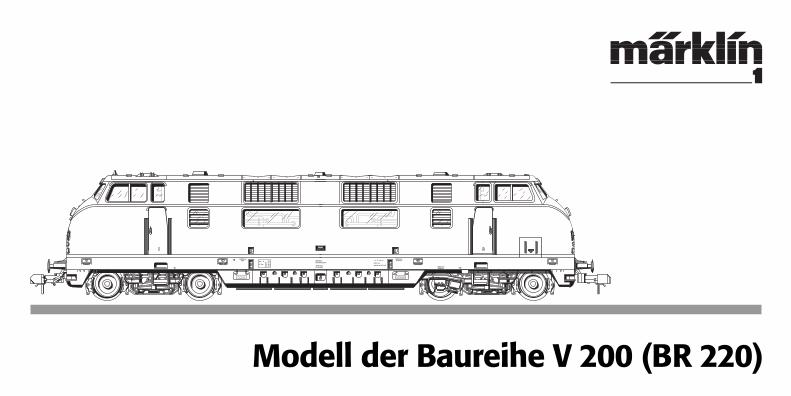
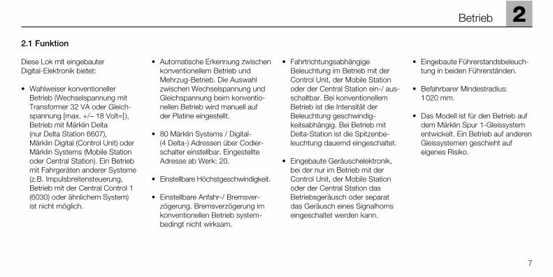
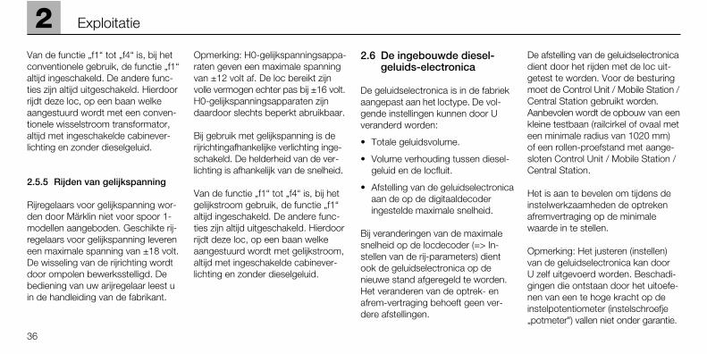
Modell der Baureihe V 200 (BR 220)
EinfüllstutzenHeizöl
Löschanlage
Gew ok
GewBr
79 t97 t74 t58 t
SPG
EinfüllstutzenKraftstoff
Feuerlöschschlauchund Anschlußstutzen
EinfüllstutzenKühlwasser
BD HamburgBW Hamburg-Altona
AW NürnbergUnt 27.8.56
Kssbr. m. Z.letzte Br Unt. 27. 8.57
11, 50 m
220 022-8
2 Betrieb Seite 7 Operation Page 15 Fonctionnement Page 23 Exploitatie Blz. 31
1 Exploitation Vorbild Seite 4 Prototype Page 4 dans le réel Page 4 Grootbedrijf Blz. 4
3 Betrieb auf Operation on Exploitation Bedrijf opder Anlage Seite 39 a layout Page 39 sur réseau Page 39 een modelbaan Blz. 39
4 Wartung Seite 41 Maintenance Page 41 Entretien Page 41 Onderhoud Blz. 41
3
4
1 Vorbild Prototype Exploitation dans le réel Grootbedrijf
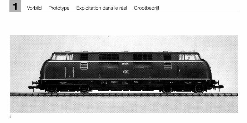
Informationen zum Vorbild
Schon kurze Zeit nach der Gründung der Deutschen Bundesbahn wurdendie Weichen für die zukünftige Entwicklung gestellt. Stand früher dieDampflokomotive im Mittelpunkt der Lokplanung, so wurde nun der Elektro-und Dieselantrieb bevorzugt.
Schon 1953 wurde der Öffentlichkeit der erste Prototyp der neuen V200 vor-gestellt, eine Maschine für den schweren Streckendienst. Die Serienversionenwurden ab 1956 geliefert. Zusammen mit dem TEE-Triebzug war diese Lokdamals eine der Vorzeige-Fahrzeuge der DB.
Die V 200 bewährte sich nicht nur vor F- und D-Zügen sondern verrichtetegenauso erfolgreich vor Güterzügen ihren Dienst.
Die Baureihe V 200 besaß 2 Motoren, die einzeln oder zusammen je nachLeistungsanforderung eingeschaltet wurden.
Informationen zum Modell
Das Modell ist mit einer Geräuschelektronik ausgestattet, die im Betrieb mitMärklin Digital das Geräusch von einem oder zwei Dieselmotoren wiedergibt.Bei dieser Geräuschelektronik werden digital aufgenommene, bearbeiteteund gespeicherte Tonaufnahmen passend zum jeweiligen Betriebszustanddes Modells wiedergegeben.
Information about the prototype
A short time after the founding of the German Federal Railroad the path waschosen for future development. In the past steam locomotives had been thecenter of locomotive planning; now electric and diesel motive power wouldbe given preference.
The first prototype of the new V 200, a locomotive for heavy main line service,was presented to the public as early as 1953. Regular production versionswere delivered starting in 1956. Together with the TEE railcar train, this loco-motive was one of the DB’s pieces of motive power that showed the way ofthe future at that time.
The V 200 proved itself in service on the point of freight trains as well as withlong distance and regular express trains.
The class V200 had 2 motors that could be switched on individually or together,depending on the power requirements.
Information about the model
This model is equipped with a sound effects circuit that reproduces thesound of one or two diesel motors, when the locomotive is operated withMärklin Digital. With this sound effects circuit digitally recorded, processedand stored sound images are reproduced according to the operating statusof the locomotive.
1
5
Vorbild Prototype
Information sur le modèle réel
Après la fondation des Chemins de fer de la Deutsche Bundesbahn, il ne fallutpas attendre très longtemps pour que les grandes lignes du développementfutur soient tracées. Autant la locomotive à vapeur se trouvait jadis au centrede la planification des locomotives, autant on privilégia désormais la motori-sation électrique et Diesel.
En 1953 déjà eut lieu la presentation publique du premier prototype de lanouvelle V 200, une machine destinée au difficile service de ligne. Les versionsde série furent livrées à partir de 1956. A l’époque, comme la rame auto-motrice TEE, cette locomotive était l’un des véhicules de prestige de la DB.
Non seulement la V 200 fit ses preuves à la tête des trains de grands parcourset les express mais elle s’acquitta de sa tâche avec autant de succès entractant des trains de marchandises.
La série V 200 est équipée de deux moteurs qui sont mis en marche séparé-ment ou ensemble selon la demande en puissance désirée.
Information sur le modèle réduit
Le modèle est équipé d’un bruiteur électronique qui, en exploitation avec MärklinDigital, restitue le bruit d’un ou de deux moteurs diesels. Grâce à ce bruiteurélectronique, les différents bruits – collectés sur le terrain, retravaillés et enregis-trés numériquement – sont restitués en fonction de l’état opérationnel du modèle.
Informatie over het voorbeeld
Korte tijd na het oprichten van de Deutschen Bundesbahn (Duitse spoorwegen) werd een nieuwe weg ingeslagen voor de toekomstigeontwikkeling. Stond vroeger de stoomloc in het middelpunt van de locplan-ning, nu hadden elektrische en diesellocomotieven de voorkeur.
Reeds in 1953 werd het eerste prototype aan het publiek gepresenteerd, deV 200, een machine voor het zware werk. De versie uit de serieproduktiewerd vanaf 1956 uitgeleverd. Samen met het TEE-treinstel was deze locdestijds een van de “voorbeeld-treinen” van de DB.
De V 200 bewees zich niet alleen voor de zgn F- en D-treinen doch verrichtteook in de goederendienst uitstekende prestaties.
De serie V 200 had 2 motoren die, afhankelijk van het benodigde vermogenafzonderlijk of gezamenlijk, ingeschakeld werden.
Informatie over het model
Het model is uitgerust met een geluidselektronica die, bij het gebruik met Märklin digitaal, het geluid van één of twee dieselmotoren weer-geeft. Bij deze geluidselektronica worden de geluidsopnamen, die digitaalopgenomen, bewerkt en opgeslagen zijn, overeenkomstig de bedrijfssituatievan het model weergegeven.
6
1 Exploitation dans le réel Grootbedrijf
7
Betrieb
2.1 Funktion
Diese Lok mit eingebauterDigital-Elektronik bietet:
• Wahlweiser konventioneller Betrieb (Wechselspannung mitTransformer 32 VA oder Gleich-spannung [max. +/– 18 Volt=] ),Betrieb mit Märklin Delta (nur Delta Station 6607), Märklin Digital (Control Unit) oderMärklin Systems (Mobile Stationoder Central Station). Ein Betriebmit Fahrgeräten anderer Systeme(z.B. Impulsbreitensteuerung,Betrieb mit der Central Control 1(6030) oder ähnlichem System) ist nicht möglich.
• Automatische Erkennung zwischenkonventionellem Betrieb undMehrzug-Betrieb. Die Auswahlzwischen Wechselspannung undGleichspannung beim konventio-nellen Betrieb wird manuell auf der Platine eingestellt.
• 80 Märklin Systems / Digital- (4 Delta-) Adressen über Codier-schalter einstellbar. EingestellteAdresse ab Werk: 20.
• Einstellbare Höchstgeschwindigkeit.
• Einstellbare Anfahr-/ Bremsver-zögerung. Bremsverzögerung imkonventionellen Betrieb system-bedingt nicht wirksam.
• Fahrtrichtungsabhängige Beleuchtung im Betrieb mit der Control Unit, der Mobile Stationoder der Central Station ein-/ aus-schaltbar. Bei konventionellemBetrieb ist die Intensität derBeleuchtung geschwindig-keitsabhängig. Bei Betrieb mitDelta-Station ist die Spitzenbe-leuchtung dauernd eingeschaltet.
• Eingebaute Geräuschelektronik,bei der nur im Betrieb mit derControl Unit, der Mobile Stationoder der Central Station dasBetriebsgeräusch oder separatdas Geräusch eines Signalhornseingeschaltet werden kann.
• Eingebaute Führerstandsbeleuch-tung in beiden Führerständen.
• Befahrbarer Mindestradius: 1020 mm.
• Das Modell ist für den Betrieb aufdem Märklin Spur 1-Gleissystementwickelt. Ein Betrieb auf anderenGleissystemen geschieht auf eigenes Risiko.
2
Betrieb
8
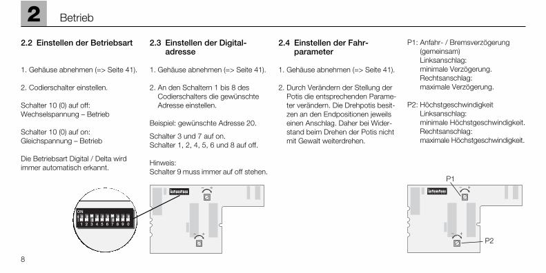
22.2 Einstellen der Betriebsart
1. Gehäuse abnehmen (=> Seite 41).
2. Codierschalter einstellen.
Schalter 10 (0) auf off: Wechselspannung – Betrieb
Schalter 10 (0) auf on: Gleichspannung – Betrieb
Die Betriebsart Digital / Delta wirdimmer automatisch erkannt.
2.3 Einstellen der Digital-adresse
1. Gehäuse abnehmen (=> Seite 41).
2. An den Schaltern 1 bis 8 desCodierschalters die gewünschteAdresse einstellen.
Beispiel: gewünschte Adresse 20.
Schalter 3 und 7 auf on. Schalter 1, 2, 4, 5, 6 und 8 auf off.
Hinweis: Schalter 9 muss immer auf off stehen.
2.4 Einstellen der Fahr-parameter
1. Gehäuse abnehmen (=> Seite 41).
2. Durch Verändern der Stellung derPotis die entsprechenden Parame-ter verändern. Die Drehpotis besit-zen an den Endpositionen jeweilseinen Anschlag. Daher bei Wider-stand beim Drehen der Potis nichtmit Gewalt weiterdrehen.
P1: Anfahr- / Bremsverzögerung(gemeinsam)Linksanschlag: minimale Verzögerung.Rechtsanschlag: maximale Verzögerung.
P2: HöchstgeschwindigkeitLinksanschlag: minimale Höchstgeschwindigkeit.Rechtsanschlag: maximale Höchstgeschwindigkeit.
P1
P2

2
9
Betrieb
Digital Digital Digital
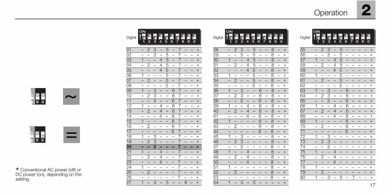
28 – 2 3 – 5 – – 8 – *29 – – 3 – 5 – – 8 – *30 1 – – 4 5 – – 8 – *31 – 2 – 4 5 – – 8 – *32 – – – 4 5 – – 8 – *33 1 – – – 5 – – 8 – *34 – 2 – – 5 – – 8 – *35 – – – – 5 – – 8 – *36 1 – 3 – – 6 – 8 – *37 – 2 3 – – 6 – 8 – *38 – – 3 – – 6 – 8 – *39 1 – – 4 – 6 – 8 – *40 – 2 – 4 – 6 – 8 – *41 – – – 4 – 6 – 8 – *42 1 – – – – 6 – 8 – *43 – 2 – – – 6 – 8 – *44 – – – – – 6 – 8 – *45 1 – 3 – – – – 8 – *46 – 2 3 – – – – 8 – *47 – – 3 – – – – 8 – *48 1 – – 4 – – – 8 – *49 – 2 – 4 – – – 8 – *50 – – – 4 – – – 8 – *51 1 – – – – – – 8 – *52 – 2 – – – – – 8 – *53 – – – – – – – 8 – *54 1 – 3 – 5 – – – – *
55 – 2 3 – 5 – – – – *56 – – 3 – 5 – – – – *57 1 – – 4 5 – – – – *58 – 2 – 4 5 – – – – *59 – – – 4 5 – – – – *60 1 – – – 5 – – – – *61 – 2 – – 5 – – – – *62 – – – – 5 – – – – *63 1 – 3 – – 6 – – – *64 – 2 3 – – 6 – – – *65 – – 3 – – 6 – – – *66 1 – – 4 – 6 – – – *67 – 2 – 4 – 6 – – – *68 – – – 4 – 6 – – – *69 1 – – – – 6 – – – *70 – 2 – – – 6 – – – *71 – – – – – 6 – – – *72 1 – 3 – – – – – – *73 – 2 3 – – – – – – *74 – – 3 – – – – – – *75 1 – – 4 – – – – – *76 – 2 – 4 – – – – – *77 – – – 4 – – – – – *78 1 – – – – – – – – *79 – 2 – – – – – – – *80 1 – 3 – 5 – 7 – – *
01 – 2 3 – 5 – 7 – – *02 – – 3 – 5 – 7 – – *03 1 – – 4 5 – 7 – – *04 – 2 – 4 5 – 7 – – *05 – – – 4 5 – 7 – – *06 1 – – – 5 – 7 – – *07 – 2 – – 5 – 7 – – *08 – – – – 5 – 7 – – *09 1 – 3 – – 6 7 – – *10 – 2 3 – – 6 7 – – *11 – – 3 – – 6 7 – – *12 1 – – 4 – 6 7 – – *13 – 2 – 4 – 6 7 – – *14 – – – 4 – 6 7 – – *15 1 – – – – 6 7 – – *16 – 2 – – – 6 7 – – *17 – – – – – 6 7 – – *18 1 – 3 – – – 7 – – *19 – 2 3 – – – 7 – – *20 – – 3 – – – 7 – – *21 1 – – 4 – – 7 – – *22 – 2 – 4 – – 7 – – *23 – – – 4 – – 7 – – *24 1 – – – – – 7 – – *25 – 2 – – – – 7 – – *26 – – – – – – 7 – – *27 1 – 3 – 5 – – 8 – *
~
9 0 =
9 0
* Je nach Stellung konventionellerWechselstrom (off)Gleichstrombetrieb (on).
10
2 Betrieb
2.5 Betrieb mit den einzelnenVersorgungs-Systemen
Dieses Modell ist zum wahlweisenBetrieb mit Märklin Systems (Mobile Station oder Central Station),Märklin Digital (nur Control Unit alsZentrale), Märklin Delta, Wechsel-strom (nur Märklin Transformer 32 VA)oder Gleichstrom (Fahrgerät mit einer maximalen Spannung von +/– 18 Volt =) geeignet. Schäden, die beim Betrieb mit einem anderenBetriebssystem entstehen, beruhenauf einem nicht erlaubten Betriebs-zustand und sind daher nicht durchdie Gewährleistungspflicht oder dieHerstellergarantie abgedeckt. Für allehieraus entstehenden Schäden haftetder Anwender.
2.5.1 Betrieb mit der Mobile Station/Central Station
Zur Aufnahme dieser Lokomotive indie Lokliste lesen Sie bitte die Ge-brauchsanleitung zur Mobile Stationoder Central Station. Zur Anwahl der Lokomotive aus der Datenbankbenutzen Sie bitte die Artikelnummer,die Sie z. B. auf der Lokverpackungfinden. Folgende Schaltfunktionenstehen Ihnen zur Verfügung:
• Fahrtrichtungsabhängige Beleuch-tung ein/aus.
• Führerstandsbeleuchtung ein/aus.
• Betriebsgeräusch (Motor 1) ein/aus.
• Geräusch eines Signalhorns ein/aus.
• Betriebsgeräusch (Motor 2) ein/aus.
2.5.2 Betrieb mit Digital
Hinweis: Zum Fahrbetrieb können alle MärklinZentraleinheiten mit dem Motorola-Übertragungsformat verwendet wer-den. Der volle Funktionsumfang stehtjedoch nur mit der Control Unit 6021zur Verfügung. Bei Verwendung derfrüheren Central Unit 6020 oder einerbaugleichen Version können dieFunktionen F1 bis F4 nicht geschaltetwerden. Es entfällt auch die Fahrt-richtungsanzeige.
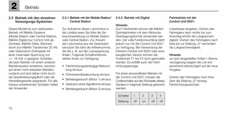
Für einen einwandfreien Betrieb mitder Control Unit 6021 müssen dieCodierschalter auf der Rückseite diesesGerätes in folgende Stellung gebrachtwerden:
Schalter: 1 2 3 4
Stellung: off on off off
Fahrbetrieb mit der Control Unit 6021:
Lokadresse eingeben. Drehen desFahrreglers nach rechts bis zumAnschlag erhöht die Lokgeschwin-digkeit. Drehen des Fahrreglers nachlinks bis zur Stellung „0“ vermindertdie Lokgeschwindigkeit.
Hinweis: Je nach eingestellter Anfahr-/ Brems-verzögerung reagiert die Lok ent-sprechend zeitverzögert auf die neueVorgabe.
Drehen des Fahrreglers nach linksüber die Stellung „0“ hinweg: Fahrtrichtungswechsel.

2
11
Betrieb
Hinweis: Die Fahrtrichtung wird bei der Control Unit 6021 über zwei Pfeilerechts neben der Adressanzeigeangezeigt.
Pfeil nach oben: Lok fährt vorwärts. Pfeil nach unten: Lok fährt rückwärts.
Drücken der Taste „function“: Einschalten der Beleuchtung.
Drücken der Taste „off“: Ausschalten der Beleuchtung.
Drücken der Taste „f1“: Einschalten der Führerstandsbe-leuchtung.Durch ein weiteres Betätigen derTaste „f1“ wird die Führerstands-beleuchtung wieder ausgeschaltet.
Drücken der Taste „f2“: Betriebsgeräusch (Motor 1) ein.
Durch ein weiteres Betätigen derTaste „f2“ wird das Geräusch wiederausgeschaltet.
Drücken der Taste „f3“:Einschalten des Geräuschs einesSignalhorns. Anschließend unbedingtdurch ein weiteres Betätigen derTaste „f3“ die Funktion ausschalten!Sonst kann es zu Fehlfunktionenkommen.
Drücken der Taste „f4“: Betriebsgeräusch (Motor 2) ein. Durch ein weiteres Betätigen derTaste „f4“ wird das Geräusch wiederausgeschaltet.
2.5.3 Fahren der Lok mit Delta
Zum Fahren der Lok mit Märklin Deltawird an dem Handregler Delta Mobildie eingestellte Lokadresse angewählt.
Durch Drehen des Fahrreglers ausder Mittelstellung heraus nach rechtsfährt die Lok vorwärts. Durch Drehendes Fahrreglers aus der Mittelstellungnach links fährt die Lok rückwärts.Die fahrtrichtungsabhängige Beleuch-tung ist dauernd eingeschaltet. Diemaximale Ausgangsleistung der Delta Station reicht zum gleichzeiti-gen Fahren von 2 bis maximal 3 ein-motorigen Lokomotiven.
Von den Funktionen f1 bis f4 ist imBetrieb mit der Delta Station dieFunktion f1 immer eingeschaltet. Dierestlichen Funktionen sind immerausgeschaltet. Daher fährt diese Lokimmer mit eingeschalteter Führer-standsbeleuchtung und ohne Diesel-geräusch im Delta-Betrieb.
2.5.4 Fahren mit Wechselspannung
In der Betriebsart „Wechselspannung“kann die Lok z.B. mit einem MärklinFahrgerät 6606 in Verbindung miteinem Transformer 6002 gesteuertwerden. Durch Drehen des Fahrreg-lers nach rechts wird die Geschwin-digkeit der Lok erhöht und durchDrehen nach links wird sie entspre-chend vermindert. Wird der Fahrreglerüber die Stellung „0“ nach links wei-ter gedreht, so wird die Fahrtrichtungumgeschaltet. Der Umschaltbefehlfür die Fahrtrichtung sollte nie an einefahrende Lok sondern immer nur aneine stehende Lok gegeben werden.
Im Betrieb mit Wechselspannung ist diefahrtrichtungsabhängige Beleuchtungeingeschaltet. Die Intensität der Be-leuchtung ist geschwindigkeitsabhängig.
12
2 Betrieb
Von den Funktionen f1 bis f4 ist imBetrieb die Funktion f1 immer einge-schaltet. Die restlichen Funktionensind immer ausgeschaltet. Daherfährt diese Lok immer mit eingeschal-teter Führerstandsbeleuchtung undohne Dieselgeräusch im Wechsel-spannungsbetrieb.
2.5.5 Fahren mit Gleichspannung
Gleichspannungs-Fahrgeräte werdenvon Märklin für Spur-1-Modelle nichtangeboten. Geeignet sind Gleich-spannungs-Fahrgeräte mit einermaximalen Spannung von ±18 Volt.Der Fahrtrichtungswechsel wirddurch einen Polaritätswechsel vorge-nommen. Die Bedienung des jeweili-gen Fahrgerätes entnehmen Sie derAnleitung des Herstellers.
Hinweis: H0-Gleichspannungs-Fahr-geräte geben eine maximale Span-nung von ±12 Volt ab. Die Lokerreicht jedoch ihre volle Leistungs-fähigkeit erst bei ±16 Volt. H0-Gleichspannungs-Fahrgeräte sinddaher nur eingeschränkt verwendbar.
Im Betrieb mit Gleichspannung ist die fahrtrichtungsabhängige Beleuch-tung eingeschaltet. Die Intensität derBeleuchtung ist geschwindigkeits-abhängig.
Von den Funktionen f1 bis f4 ist imBetrieb die Funktion f1 immer einge-schaltet. Die restlichen Funktionensind immer ausgeschaltet. Daherfährt diese Lok immer mit eingeschal-teter Führerstandsbeleuchtung undohne Dieselgeräusch im Gleichspan-nungsbetrieb.
2.6 Die eingebaute Diesel-geräuschelektronik
Die Geräuschelektronik ist ab Werkauf die Lok abgestimmt. FolgendeEinstellungen können von Ihnen verändert werden:
• Gesamtlautstärke.
• Lautstärkeverhältnis zwischen Dieselgeräusch und Lokhorn.
• Abstimmung der Geräuschelek-tronik auf die am Digitaldecodereingestellte maximale Höchst-geschwindigkeit.
Bei einer Veränderung der maximalenHöchstgeschwindigkeit am Lokdecoder(=> Einstellen der Fahrparameter)muss auch die Geräuschelektronikauf die neuen Gegebenheiten abge-stimmt werden. Eine Veränderungder Anfahr- und Bremsverzögerungbenötigt keine Abstimmarbeiten.
Die Abstimmung der Geräuschelek-tronik muss beim Fahren der Loküberprüft werden. Zur Steuerung der Lok muss die Control Unit /Mobile Station / Central Station ver-wendet werden. Wir empfehlen denAufbau einer kleinen Teststrecke(Kreis oder Oval mit Mindestradius1020 mm) oder einen Rollenprüfstandmit angeschlossener Control Unit /Mobile Station / Central Station.
Wir empfehlen, während der Einstell-arbeiten die Anfahr- und Bremsver-zögerung auf den minimalen Wert zu stellen.
Hinweis: Das Justieren der Geräusch-elektronik kann von Ihnen selbstdurchgeführt werden. Schäden, diedurch Einwirkung von hohen Kräftenauf die Potentiometer (Einstellregler,„Poti”) entstehen, sind nicht durchdie Garantie abgedeckt.
2
13
Betrieb
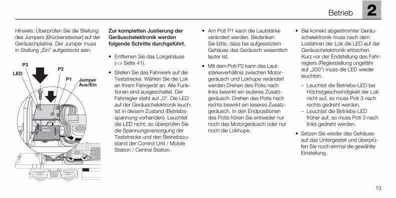
Hinweis: Überprüfen Sie die Stellungdes Jumpers (Brückenstecker) auf derGeräuschplatine. Der Jumper mussin Stellung „Ein” aufgesteckt sein.
Zur kompletten Justierung der Geräuschelektronik werden folgende Schritte durchgeführt.
• Entfernen Sie das Lokgehäuse (=> Seite 41).
• Stellen Sie das Fahrwerk auf dieTeststrecke. Wählen Sie die Lokan Ihrem Fahrgerät an. Alle Funk-tionen sind ausgeschaltet. DerFahrregler steht auf „0“. Die LEDauf der Geräuschelektronik leuch-tet in diesem Zustand (Betriebs-spannung vorhanden). Leuchtetdie LED nicht, so überprüfen Siedie Spannungsversorgung derTeststrecke und den Betriebszu-stand der Control Unit / MobileStation / Central Station.
• Am Poti P1 kann die Lautstärkeverändert werden. Bedenken Sie bitte, dass bei aufgesetztemGehäuse das Geräusch wesentlichlauter ist.
• Mit dem Poti P2 kann das Laut-stärkeverhältnis zwischen Motor-geräusch und Lokhupe verändertwerden.Drehen des Potis nachlinks bewirkt ein lauteres Zusatz-geräusch. Drehen des Potis nachrechts bewirkt ein leiseres Zusatz-geräusch. In den Endpositionendes Potis hören Sie entweder nurnoch das Motorgeräusch oder nurnoch die Lokhupe.
• Bei korrekt abgestimmter Geräu-schelektronik muss nach demLosfahren der Lok die LED auf derGeräuschelektronik erlöschen.Kurz vor der Endstellung des Fahr-reglers (Reglerstellung ungefährauf „200“) muss die LED wiederleuchten.
– Leuchtet die Betriebs-LED bei Höchstgeschwindigkeit der Lok nicht auf, so muss Poti 3 nach rechts gedreht werden.
– Leuchtet die Betriebs-LED früher auf, so muss Poti 3 nach links gedreht werden.
• Setzen Sie wieder das Gehäuseauf das Untergestell und überprü-fen Sie noch einmal die gewählteEinstellung.
14
2 Betrieb
Bitte beachten Sie folgende Punktebeim Betrieb der Geräuschelek-tronik.
• Die Geräuschelektronik benötigteine Mindest-Versorgungsspan-nung von 12 Volt. Fällt die Versor-gungsspannung unter diesenWert, so kann die Geräuschelek-tronik anschließend verzerrt oderleiser klingen oder ganz ausge-schaltet sein. Auch durch Betätigender Funktionstasten lässt sich dieserZustand nicht ändern. Erst nachDurchführen eines Nothalts (Span-nung am Gleis für ein paar Sekun-den abschalten) ist dieser Zustandbeendet. Tritt dieser Zustandimmer auf dem selben Gleisab-schnitt auf, so ist dort die Span-nungsversorgung zu überprüfen.
• Der Leistungsbedarf der Geräusch-elektronik liegt bei ca. 12 VA.Dadurch verringert sich die maxi-male Anzahl an Lokomotiven proVersorgungsbereich.
• Bei dauerndem Betrieb der Lokmit Gleich- oder Wechselspan-nung empfehlen wir den Jumperauf der Geräuschplatine in Stellung„Aus“ zu stecken.
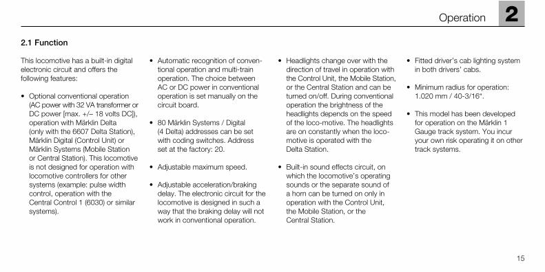
2.1 Function
This locomotive has a built-in digitalelectronic circuit and offers the following features:
• Optional conventional operation(AC power with 32 VA transformer orDC power [max. +/– 18 volts DC]),operation with Märklin Delta (only with the 6607 Delta Station),Märklin Digital (Control Unit) orMärklin Systems (Mobile Station or Central Station). This locomotiveis not designed for operation withlocomotive controllers for othersystems (example: pulse widthcontrol, operation with the Central Control 1 (6030) or similarsystems).
• Automatic recognition of conven-tional operation and multi-trainoperation. The choice between AC or DC power in conventionaloperation is set manually on thecircuit board.
• 80 Märklin Systems / Digital (4 Delta) addresses can be setwith coding switches. Address set at the factory: 20.
• Adjustable maximum speed.
• Adjustable acceleration/brakingdelay. The electronic circuit for thelocomotive is designed in such away that the braking delay will notwork in conventional operation.
• Headlights change over with thedirection of travel in operation withthe Control Unit, the Mobile Station,or the Central Station and can beturned on/off. During conventionaloperation the brightness of theheadlights depends on the speedof the loco-motive. The headlightsare on constantly when the loco-motive is operated with the Delta Station.
• Built-in sound effects circuit, onwhich the locomotive’s operatingsounds or the separate sound of a horn can be turned on only inoperation with the Control Unit,the Mobile Station, or the Central Station.
• Fitted driver’s cab lighting systemin both drivers’ cabs.
• Minimum radius for operation: 1.020 mm / 40-3/16“.
• This model has been developedfor operation on the Märklin 1Gauge track system. You incuryour own risk operating it on othertrack systems.
2
15
Operation
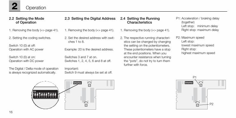
2.2 Setting the Mode of Operation
1. Removing the body (=> page 41).
2. Setting the coding switches.
Switch 10 (0) at off: Operation with AC power
Switch 10 (0) at on: Operation with DC power
The Digital / Delta mode of operationis always recognized automatically.
2.3 Setting the Digital Address
1. Removing the body (=> page 41).
2. Set the desired address with swit-ches 1 to 8.
Example: 20 is the desired address.
Switches 3 and 7 at on. Switches 1, 2, 4, 5, 6 and 8 at off.
Important: Switch 9 must always be set at off.
2.4 Setting the Running Characteristics
1. Removing the body (=> page 41).
2. The respective running characteri-stics can be changed by changingthe setting on the potentiometers.These potentiometers have a stopat the end positions. When youencounter resistance when turningthe “pots”, do not try to turn themfurther with force.
P1: Acceleration / braking delay(together)Left stop: minimum delayRight stop: maximum delay
P2: Maximum speedLeft stop: lowest maximum speed Right stop: highest maximum speed
16
2 Operation
P1
P2
2
17
Operation
~
9 0 =
9 0
* Conventional AC power (off) or DC power (on), depending on the setting.
Digital Digital Digital
28 – 2 3 – 5 – – 8 – *29 – – 3 – 5 – – 8 – *30 1 – – 4 5 – – 8 – *31 – 2 – 4 5 – – 8 – *32 – – – 4 5 – – 8 – *33 1 – – – 5 – – 8 – *34 – 2 – – 5 – – 8 – *35 – – – – 5 – – 8 – *36 1 – 3 – – 6 – 8 – *37 – 2 3 – – 6 – 8 – *38 – – 3 – – 6 – 8 – *39 1 – – 4 – 6 – 8 – *40 – 2 – 4 – 6 – 8 – *41 – – – 4 – 6 – 8 – *42 1 – – – – 6 – 8 – *43 – 2 – – – 6 – 8 – *44 – – – – – 6 – 8 – *45 1 – 3 – – – – 8 – *46 – 2 3 – – – – 8 – *47 – – 3 – – – – 8 – *48 1 – – 4 – – – 8 – *49 – 2 – 4 – – – 8 – *50 – – – 4 – – – 8 – *51 1 – – – – – – 8 – *52 – 2 – – – – – 8 – *53 – – – – – – – 8 – *54 1 – 3 – 5 – – – – *
55 – 2 3 – 5 – – – – *56 – – 3 – 5 – – – – *57 1 – – 4 5 – – – – *58 – 2 – 4 5 – – – – *59 – – – 4 5 – – – – *60 1 – – – 5 – – – – *61 – 2 – – 5 – – – – *62 – – – – 5 – – – – *63 1 – 3 – – 6 – – – *64 – 2 3 – – 6 – – – *65 – – 3 – – 6 – – – *66 1 – – 4 – 6 – – – *67 – 2 – 4 – 6 – – – *68 – – – 4 – 6 – – – *69 1 – – – – 6 – – – *70 – 2 – – – 6 – – – *71 – – – – – 6 – – – *72 1 – 3 – – – – – – *73 – 2 3 – – – – – – *74 – – 3 – – – – – – *75 1 – – 4 – – – – – *76 – 2 – 4 – – – – – *77 – – – 4 – – – – – *78 1 – – – – – – – – *79 – 2 – – – – – – – *80 1 – 3 – 5 – 7 – – *
01 – 2 3 – 5 – 7 – – *02 – – 3 – 5 – 7 – – *03 1 – – 4 5 – 7 – – *04 – 2 – 4 5 – 7 – – *05 – – – 4 5 – 7 – – *06 1 – – – 5 – 7 – – *07 – 2 – – 5 – 7 – – *08 – – – – 5 – 7 – – *09 1 – 3 – – 6 7 – – *10 – 2 3 – – 6 7 – – *11 – – 3 – – 6 7 – – *12 1 – – 4 – 6 7 – – *13 – 2 – 4 – 6 7 – – *14 – – – 4 – 6 7 – – *15 1 – – – – 6 7 – – *16 – 2 – – – 6 7 – – *17 – – – – – 6 7 – – *18 1 – 3 – – – 7 – – *19 – 2 3 – – – 7 – – *20 – – 3 – – – 7 – – *21 1 – – 4 – – 7 – – *22 – 2 – 4 – – 7 – – *23 – – – 4 – – 7 – – *24 1 – – – – – 7 – – *25 – 2 – – – – 7 – – *26 – – – – – – 7 – – *27 1 – 3 – 5 – – 8 – *
18
2 Operation
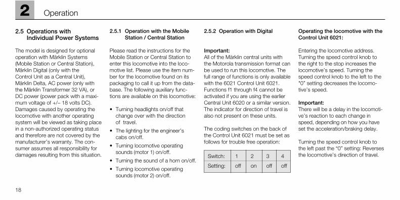
2.5 Operations with Individual Power Systems
The model is designed for optionaloperation with Märklin Systems(Mobile Station or Central Station),Märklin Digital (only with the Control Unit as a Central Unit), Märklin Delta, AC power (only withthe Märklin Transformer 32 VA), orDC power (power pack with a maxi-mum voltage of +/– 18 volts DC).Damages caused by operating thelocomotive with another operatingsystem will be viewed as taking placein a non-authorized operating statusand therefore are not covered by themanufacturer’s warranty. The con-sumer assumes all responsibility fordamages resulting from this situation.
2.5.1 Operation with the MobileStation / Central Station
Please read the instructions for theMobile Station or Central Station toenter this locomotive into the loco-motive list. Please use the item num-ber for the locomotive found on itspackaging to call it up from the data-base. The following auxiliary func-tions are available on this locomotive:
• Turning headlights on/off thatchange over with the direction of travel.
• The lighting for the engineer’scabs on/off.
• Turning locomotive operatingsounds (motor 1) on/off.
• Turning the sound of a horn on/off.
• Turning locomotive operatingsounds (motor 2) on/off.
2.5.2 Operation with Digital
Important:All of the Märklin central units withthe Motorola transmission format canbe used to run this locomotive. Thefull range of functions is only availablewith the 6021 Control Unit 6021.Functions f1 through f4 cannot beactivated if you are using the earlierCentral Unit 6020 or a similar version.The indicator for direction of travel isalso not present on these units.
The coding switches on the back ofthe Control Unit 6021 must be set asfollows for trouble free operation:
Switch: 1 2 3 4
Setting: off on off off
Operating the locomotive with theControl Unit 6021:
Entering the locomotive address.Turning the speed control knob tothe right to the stop increases thelocomotive’s speed. Turning thespeed control knob to the left to the"0” setting decreases the locomo-tive’s speed.
Important: There will be a delay in the locomoti-ve’s reaction to each change inspeed, depending on how you haveset the acceleration/braking delay.
Turning the speed control knob tothe left past the “0” setting: Reversesthe locomotive’s direction of travel.
2
19
Operation
Important: On the Control Unit 6021 two arrowsto the right of the address displayindicate the direction of travel for thelocomotive.
Arrow pointing up: Locomotive runs forward.
Arrow pointing down: Locomotive runs in reverse.
Pressing the “function” button: Turns the headlights on.
Pressing the “off” button: Turns the headlights off.
Pressing button “f1”: Turns the lighting for the engineer’scabs on.Pressing button “f1” again turns thelighting for the engineer’s cabs off.
Pressing button “f2”: Turning locomotiv operating sounds(motor 1) on.Pressing button “f2” again turns thesound effects off.
Pressing button “f3”: Turns the sound of a horn on. Nowquickly turn this function off bypressing button “f3” again! Otherwise,it can lead to malfunctions.
Pressing button “f4”: Turning locomotiv operating sounds(motor 2) on.Pressing button “f4” again turns thesound effects off.
2.5.3 Operating the locomotive with Delta
To operate the locomotive with Märklin Delta you use the Delta-Mobil
to select the address that has beenset on the former. The locomotive willrun forward when you turn the speedcontrol knob to the right of the centerposition. Turning the speed controlknob to the left of the center positionwill cause the locomotive to run inreverse. The headlights changedirection with the direction of traveland are on all of the time. The maxi-mum power output of the Delta-Station is sufficient to operate 2 to a maximum of 3 single motor loco-motives at the same time.
Of the functions f1 to f4, the function f1is on continuously when operatingthe locomotive with the Delta Station.The other functions remain off. Forthat reason this locomotive will alwaysoperate with the engineer’s cab lightingturned on without diesel motor soundeffects in Delta operation.
2.5.3 Operating the locomotive on alternating current
With “AC power” the locomotive canbe controlled with a 6606 Märklinlocomotive controller in conjunctionwith a 6001/6002 transformer, forexample. Locomotive speed is in-creased by turning the control knobto the right and is decreased by tur-ning the knob to the left. The direc-tion of travel is changed by turningthe control knob to the left past the“0” setting. The command to reverseshould be given only to a standinglocomotive, never to one in motion.
In operation with alternating currentthe headlights change direction withthe direction of travel and are on allof the time. The intensity of the head-lights depends on the speed of thelocomotive.
Of the functions f1 to f4, the function f1is on continuously when operatingthe locomotive with conventionel AC power. The other functionsremain off. For that reason this loco-motive will always operate with theengineer’s cab lighting turned onwithout diesel motor sound effects in AC power operation.
2.5.5 Operating the locomotive on direct current
Märklin does not offer DC powerpacks for 1 Gauge models. SuitableDC power packs are those with amaximum current of ±18 volts.Direction reversing is done by rever-sing polarity. The manufacturerísinstructions for a particular make ofpower pack will give directions onhow to use it to operate a locomotive.
Tip: H0 DC power packs supply amaximum voltage of ±12 volts. Thislocomotive reaches its full potential at±16 volts. H0 DC power packs cantherefore be used only with limitations.
In operation with direct current theheadlights change direction with thedirection of travel and are on all ofthe time. The intensity of the head-lights depends on the speed of thelocomotive.
Of the functions f1 to f4, the function f1is on continuously when operatingthe locomotive with conventionel DC power. The other functionsremain off. For that reason this loco-motive will always operate with theengineer’s cab lighting turned onwithout diesel motor sound effects in DC power operation.
2.6 The built-in diesel sound effects circuit
This sound effects circuit was tunedat the factory for this locomotive. The following settings can be changedby you:
• Total volume.
• Volume relationship between the diesel sound effects and thelocomotive's horn.
• Relationship of the sound effectscircuit to the maximum speed seton the digital decoder.
When changing the maximum speedon the locomotive decoder (=> Settingthe Running Characteristics) the soundeffects circuit must also be adjustedto the new conditions. No adjust-ments in the sound effects circuit arerequired when changes are made inthe acceleration and braking delay.
The adjustments to the sound effectscircuit should be checked by opera-ting the locomotive. The Control Unit /Mobile Station / Central Station mustbe used to control the locomotive.We recommend setting up a smalltest track (circle or oval with a mini-mum radius of 1,020 mm or 40-5/32")or a test stand with a Control Unit /Mobile Station / Central Stationconnected to it. We recommend setting the acceleration and brakingdelay at the minimum value duringthe adjustment work.
Important: You can carry out adjust-ments to the sound effects circuityour-self. Damage to the potentio-meters on the circuit board causedby too much force applied to themare not covered by the warranty.
20
2 Operation
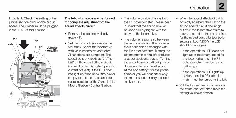
Important: Check the setting of thejumper (bridge plug) on the circuitboard. The jumper must be pluggedin the "EIN" ("ON") position.
The following steps are performedfor complete adjustment of thesound effects circuit.
• Remove the locomotive body (page 41).
• Set the locomotive frame on thetest track. Select the locomotivewith your locomotive controller. All functions are turned off. Thespeed control knob is at "0". TheLED on the sound effects circuit is now lit up in this state (operatingcurrent present). If the LED doesnot light up, then check the powersupply for the test track and theoperating status of the Control Unit /Mobile Station / Central Station.
• The volume can be changed withthe P1 potentiometer. Please bearin mind that the sound level willbe considerably higher with thebody on the locomotive.
• The volume relationship betweenthe motor noise and the locomo-tive's horn can be changed withthe P2 potentiometer. Turning thepotentiometer to the left producesa louder additional sound. Turningthe potentiometer to the right pro-duces a softer additional sound. At the end settings for the poten-tiometer you will hear either onlythe motor sound or only the loco-motive horn.
• When the sound effects circuit iscorrectly adjusted, the LED on thesound effects circuit should go out after the locomotive starts tomove. Just before the end settingfor the speed controller (controllersetting at bout "200") the LEDshould go on again.
– If the operations LED does not light up at maximum speed for the locomotive, then the P3 potentiometer must be turned to the right.
– If the operations LED lights up earlier, then the P3 potentio-meter must be turned to the left.
• Put the locomotive body back onthe frame and test once more thesetting you have chosen.
2
21
Operation
22
2 Operation
Please note the following pointswhen operating the sound effectscircuit.
• The sound effects circuit a mini-mum power supply of 12 volts. If the power supply falls below thislevel, the sound effects circuit mayproduce distorted sound, become softer in volume or turn itself offcompletely. This condition will notchange by manipulating the func-tion buttons. This status is notended until after an emergencystop has been carried out (voltagein the track is turned off for a fewseconds). If this condition occurson a particular stretch of track,then you must check to make surethat sufficient voltage is present inthat area of track.
• The power requirement for thesound effects circuit is about 12 VA.This will limit the maximum numberof locomotives that can be operatedin a power consumption area.
• We recommend putting the jumper in the "AUS" ("OFF") setting on thesound effects circuit board whenoperating the locomotive for longperiods of time with conventional DC or AC power.
2
23
Fonctionnement
2.1 Fonctionnement
Utilisation de cette locomotiveéquipée d'une électronique Digital:
• Au choix, exploitation conven-tionnelle (courant alternatif avecTransformer 32 VA ou courantcontinu [max +/– 18 volts =] ),exploitation avec Märklin Delta(uniquement Delta Station 6607),Märklin Digital (Control Unit) ouMärklin Systems (Mobile Station ouCentral Station). Une exploitation à l’aide de régulateurs provenantd’autres systèmes (par ex. courantà impulsions de largeur variable,Central Control 1 n° 6030 ousystèmes similaires) n’est pas possible.
• Détection automatique du moded’exploitation: exploitation conven-tionnelle ou exploitation multitrain.La sélection entre le courant alternatif et le courant continu (en exploitation conventionnelle) se fait manuellement sur la platineélectronique.
• 80 adresses Märklin Systems /Digital (4 Delta) réglables via le clavier d’encodage. Adresse encodée en usine: 20.
• Vitesse maximale réglable.
• Temporisation d’accélération-freinage réglable. La temporisationde freinage n’est pas active enexploitation conventionnelle.
• Eclairage des feux de signalisation,avec inversion selon sens de marche, activable/désactivable enexploitation avec la Control Unit, laMobile Station ou la Central Station.En exploitation conventionnelle,l’intensité des feux dépend de lavitesse (tension appliquée à la voie).En exploitation avec la StationDelta 6607, les feux sont activésen permanence.
• Bruiteur électronique intégré per-mettant l’activation du bruitage demoteur diesel ou du bruitageséparé d’un avertisseur sonoreuniquement en exploitation avec laControl Unit, la Mobile Station oula Central Station.
• Éclairage du poste de commandemonté dans les deux postes decommande.
• Rayon minimal d’inscription encourbe: 1020 mm.
• Le modèle réduit a été conçu pourrouler sur les voies du système devoies Märklin 1. Une exploitationsur des voies d’autres systèmescomporte des risques.
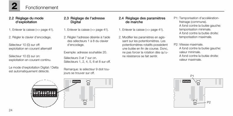
2.2 Réglage du mode d'exploitation
1. Enlever la caisse (=> page 41).
2. Régler le clavier d'encodage.
Sélecteur 10 (0) sur off: exploitation en courant alternatif
Sélecteur 10 (0) sur on: exploitation en courant continu.
Le mode d'exploitation Digital / Deltaest automatiquement détecté.
2.3 Réglage de l'adresse Digital
1. Enlever la caisse (=> page 41).
2. Régler l'adresse désirée à l'aidedes sélecteurs 1 à 8 du clavierd'encodage.
Exemple: adresse souhaitée 20.
Sélecteurs 3 et 7 sur on. Sélecteurs 1, 2, 4, 5, 6 et 8 sur off.
Remarque: le sélecteur 9 doit tou-jours se trouver sur off.
2.4 Réglage des paramètres de marche
1. Enlever la caisse (=> page 41).
2. Modifier les paramètres en agis-sant sur les potentiomètres. Lespotentiomètres rotatifs possèdentune butée en fin de course. Donc,ne pas forcer la rotation dès qu'u-ne résistance se fait sentir.
P1: Temporisation d'accélération-freinage (commune).A fond contre la butée gauche: temporisation minimale. A fond contre la butée droite: temporisation maximale.
P2: Vitesse maximale.A fond contre la butée gauche:valeur minimale.A fond contre la butée droite:valeur maximale.
24
2 Fonctionnement
P1
P2
2
25
Fonctionnement
~
9 0 =
9 0
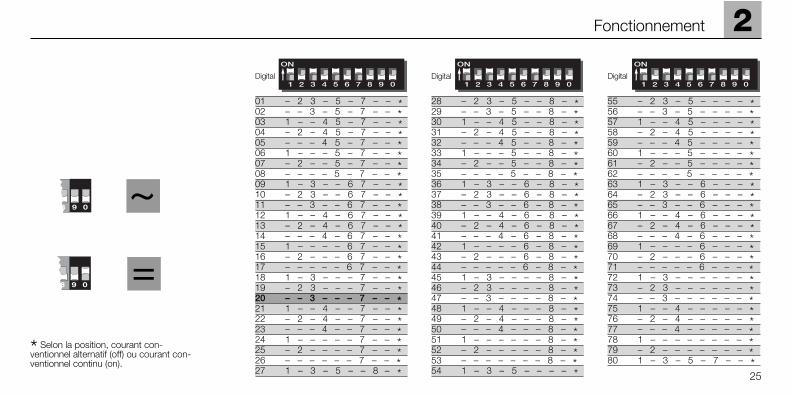
* Selon la position, courant con-ventionnel alternatif (off) ou courant con-ventionnel continu (on).
Digital Digital Digital
28 – 2 3 – 5 – – 8 – *29 – – 3 – 5 – – 8 – *30 1 – – 4 5 – – 8 – *31 – 2 – 4 5 – – 8 – *32 – – – 4 5 – – 8 – *33 1 – – – 5 – – 8 – *34 – 2 – – 5 – – 8 – *35 – – – – 5 – – 8 – *36 1 – 3 – – 6 – 8 – *37 – 2 3 – – 6 – 8 – *38 – – 3 – – 6 – 8 – *39 1 – – 4 – 6 – 8 – *40 – 2 – 4 – 6 – 8 – *41 – – – 4 – 6 – 8 – *42 1 – – – – 6 – 8 – *43 – 2 – – – 6 – 8 – *44 – – – – – 6 – 8 – *45 1 – 3 – – – – 8 – *46 – 2 3 – – – – 8 – *47 – – 3 – – – – 8 – *48 1 – – 4 – – – 8 – *49 – 2 – 4 – – – 8 – *50 – – – 4 – – – 8 – *51 1 – – – – – – 8 – *52 – 2 – – – – – 8 – *53 – – – – – – – 8 – *54 1 – 3 – 5 – – – – *
55 – 2 3 – 5 – – – – *56 – – 3 – 5 – – – – *57 1 – – 4 5 – – – – *58 – 2 – 4 5 – – – – *59 – – – 4 5 – – – – *60 1 – – – 5 – – – – *61 – 2 – – 5 – – – – *62 – – – – 5 – – – – *63 1 – 3 – – 6 – – – *64 – 2 3 – – 6 – – – *65 – – 3 – – 6 – – – *66 1 – – 4 – 6 – – – *67 – 2 – 4 – 6 – – – *68 – – – 4 – 6 – – – *69 1 – – – – 6 – – – *70 – 2 – – – 6 – – – *71 – – – – – 6 – – – *72 1 – 3 – – – – – – *73 – 2 3 – – – – – – *74 – – 3 – – – – – – *75 1 – – 4 – – – – – *76 – 2 – 4 – – – – – *77 – – – 4 – – – – – *78 1 – – – – – – – – *79 – 2 – – – – – – – *80 1 – 3 – 5 – 7 – – *
01 – 2 3 – 5 – 7 – – *02 – – 3 – 5 – 7 – – *03 1 – – 4 5 – 7 – – *04 – 2 – 4 5 – 7 – – *05 – – – 4 5 – 7 – – *06 1 – – – 5 – 7 – – *07 – 2 – – 5 – 7 – – *08 – – – – 5 – 7 – – *09 1 – 3 – – 6 7 – – *10 – 2 3 – – 6 7 – – *11 – – 3 – – 6 7 – – *12 1 – – 4 – 6 7 – – *13 – 2 – 4 – 6 7 – – *14 – – – 4 – 6 7 – – *15 1 – – – – 6 7 – – *16 – 2 – – – 6 7 – – *17 – – – – – 6 7 – – *18 1 – 3 – – – 7 – – *19 – 2 3 – – – 7 – – *20 – – 3 – – – 7 – – *21 1 – – 4 – – 7 – – *22 – 2 – 4 – – 7 – – *23 – – – 4 – – 7 – – *24 1 – – – – – 7 – – *25 – 2 – – – – 7 – – *26 – – – – – – 7 – – *27 1 – 3 – 5 – – 8 – *
26
2 Fonctionnement
2.5 Exploitation avec diverssystèmes d’exploitation
Ce modèle convient pour une exploi-tation au choix avec Märklin Systems(Mobile Station ou Central Station),Märklin Digital (uniquement ControlUnit en tant que centrale), MärklinDelta, en courant alternatif (unique-ment Märklin Transformer 32 VA) ou en courant continu (régulateuravec une tension maximale de +/– 18 volts =). Des dommages quisurviendraient lors d’une exploitationà l’aide d’autres systèmes d’exploi-tation seraient considérés commerésultant d’une forme d’exploitationnon autorisée et ne seraient parconséquent pas couverts par lagarantie du fabricant. Dans ce cas,l’utilisateur serait considéré commeentièrement responsable des dom-mages survenus.
2.5.1 Exploitation avec la MobileStation / la Central Station
Pour saisir cette locomotive dans laliste des locomotives, suivez lesinstructions données dans le moded’emploi de la Mobile Station ou dela Central Station. Pour sélectionnerla locomotive dans la banque dedonnées, veuillez utiliser le numérod’article qui se trouve entre autres surla boîte d’emballage. Les fonctionssuivantes sont à votre disposition:
• Eclairage de feux de signalisationavec inversion selon le sens demarche activé/désactivé.
• L’éclairage du poste de conduiteactivé/désactivé.
• Bruitage (moteur1) activé/désactivé.
• Bruitage d’un avertisseur sonoreactivé/désactivé.
• Bruitage (moteur2) activé/désactivé.
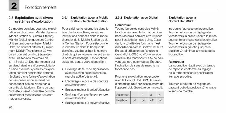
2.5.2 Exploitation avec Digital
Remarque: Toutes les unités centrales Märklinfonctionnant avec le format de don-nées Motorola peuvent être utiliséespour l'exploitation des trains. Cepen-dant, la totalité des fonctions n'estdisponible qu'avec la Control Unit 6021.En cas d'utilisation de l'ancienneCentral Unit 6020 ou d'une versionsimilaire, les fonctions f1 à f4 ne peu-vent pas être commutées. En outre,l'indication de sens de marche nefonctionne pas.
Pour une exploitation impeccableavec la Control Unit 6021, le clavier d'encodage situé sur la face arrière del'appareil doit être réglé comme suit:
Sélecteur: 1 2 3 4
Position: off on off off
Exploitation avec la Control Unit 6021:
Introduire l'adresse de locomotive.Tourner le bouton de réglage devitesse vers la droite jusqu'à la butéeaugmente la vitesse de la locomotive.Tourner le bouton de réglage devitesse vers la gauche jusqu'à laposition „0“ diminue la vitesse de lalocomotive.
Remarque:La locomotive réagit avec un tempsde réponse conforme au réglage de la temporisation d'accélération-freinage encodée.
Tourner le bouton de réglage en passant outre la position „0“ changele sens de marche.
Remarque: Sur la Control Unit 6021, le sens demarche est indiqué par les deuxflèches situées à droite de l'indica-teur d'adresse.
Flèche vers le haut: le locomotive roule en avant.
Flèche vers le bas: le locomotive roule en arrière.
Presser la touche „function“: activation des feux de signalisation.
Presser la touche „off“: désactivationdes feux de signalisation.
Une pression sur la touche „f1“:activation l’éclairage du poste deconduite.Une autre pression sur la touche „f1“désactive l’éclairage du poste deconduite.
Une pression sur la touche „f2“:Bruitage (moteur 1) acitvé. Une autre pression sur la touche „f2“désactive le bruitage.
Une pression sur la touche „f3“:Activation du bruitage de l’avertisseursonore suivie ensuite impérativementd’une autre pression sur la touche „f3“pour désactiver le bruitage sous peinede provoquer un dysfonctionnement!
Une pression sur la touche „f4“:Bruitage (moteur 2) acitvé. Une autre pression sur la touche „f4“désactive le bruitage.
2.5.3 Conduite de la locomotive en mode Delta
L'adresse qui a été réglée pour lalocomotive est choisie sur le régula-teur manuel Delta-Mobil pour per-mettre à la locomotive de fonctionner
en Märklin Delta. Si l’on actionne lerégulateur de conduite de la positioncentrale vers la droite, la locomotivese déplace en marche avant. Si l'onactionne le régulateur de conduite de la position centrale vers la gauche,la locomotive se déplace en marchearrière. L'éclairage en fonction dusens de la marche est constammentenclenché. La puissance de sortiemaximum de la Delta-Station est suffisante pour une exploitationsimultanée de 2 à 3 locomotives à un seul moteur.
En exploitation avec la Station Delta,parmi les fonctions f1 à f4, la fonc-tion f1 est toujours activée. Les fonc-tions restantes sont toujours désac-tivées. C’est pour cette raison qu’enexploitation Delta, cette locomotivecircule toujours avec l’éclairage duposte de conduite en marche et sansbruitage Diesel.
2.5.4 Conduite en tension alternative
En mode d’exploitation «Tensionalternative», la locomotive puet parexemple être commandée avec unregulateur de vitesse Märklin 6606,en association avec un transforma-teur 6002. En tournant le régulateurde vitesse vers la droite, la vitesse dela locomotive est augmentée, en letournant vers la gauche elle est réduiteen conséquence. Si le régulateur esttourné au-delà de la position «0» versla gauche, le sens de la marche estinversé. La commande d'inversion dusens de la marche ne devrait jamaisêtre transmise à une locomotive encirculation, mais toujours à une loco-motive se trouvant à l‘ arrêt.
L'éclairage en fonction du sens de lamarche est enclenché en exploitationsous tension alternative. L'intensitéde l'éclairage dépend de la vitesse.
2
27
Fonctionnement
En cours d’exploitation parmi les fon-ctions f1 à f4, la fonction f1 est tou-jours activée. Les fonctions restantessont toujours désactivées. C’est pourcette raison qu’en exploitation aveccourant alternatif, cette locomotivecircule toujours avec l’éclairage duposte de conduite en marche et sansbruitage Diesel.
2.5.5 Conduite en tension continue
Les règulateurs de vitesse à tensioncontinue ne sont pas proposés parMärklin pour les modèles de Voie 1. Les régulateurs de vitesse à tensioncontinue ayant une tension maximalede ±18 volt sont adaptés. Le chan-gement du sens de la marche est réalisé grâce à un changement depolarité. Vous trouverez les instruc-tions de commande relatives aux différents régulateurs de vitesse dansla notice du fabricant.
Indication: Les régulateurs de vitesseH0 à tension continue fournissentune tension maximum de ±12 volt.La locomotive n'atteint cependant sapleine capacité qu'avec ±16 volt. Lesrégulateurs de vitesse H0 à tensioncontinue ne peuvent donc être uti-lisés qu'avec certaines restrictions.
L'éclairage en fonction du sens de lamarche est enclenché en exploitationsous tension continue. L'intensité deléclairage dépend de la vitesse.
En cours d’exploitation parmi les fon-ctions f1 à f4, la fonction f1 est tou-jours activée. Les fonctions restantessont toujours désactivées. C’est pourcette raison qu’en exploitation aveccourant continu, cette locomotive circule toujours avec l’éclairage duposte de conduite en marche et sansbruitage Diesel.
2.6 L’Èlectronique de bruitageDiesel intégrée
L’électronique de bruitage est régléeen usine en fonction de la locomotive.Vous pouvez modifier les réglagessuivants:
• Volume sonore général.
• Balance du volume sonore entre le bruitage Diesel et le klaxon delocomotive.
• Réglage de l’électronique de bruitageen fonction de la vitesse maximaleprogrammée sur le décodeur Digital.
En cas de modification de la vitesse maximale sur le décodeur de loco-motive (=> Réglage des paramètresde marche), il faut également adapterl’électronique de bruitage aux nou-velles données. Une modification dela progressivité du démarrage et dufreinage ne nécessite aucune opéra-tion d’adaptation.
L’adaptation de l’électronique de bruitage doit être contrôlée lorsque lalocomotive circule. La Control Unit /Mobile Station / Central Station doitêtre utilisée pour commander la loco-motive. Nous recommandons demonter un petit circuit d’essai (cercleou ovale d’un rayon minimum de1020 mm) ou un banc d’essai à rouleaux avec raccordement d’uneControl Unit / Mobile Station /Central Station.
Pendant les travaux de réglage, nousrecommandons de sélectionner lavaleur minimale pour la progressivité du démarrage et du freinage.
Important: Vous pouvez procédervous-même au réglage de l’électroni-que de bruitage. Les dommages quirésulteraient de l’effet provoqué pardes puissances élevées sur lespotentiométres (régulateurs) ne sontpas couverts par la garantie.28
2 Fonctionnement

Important: Vérifiez la position du jumper (fiche en pont) sur la platinede bruitage.Le jumper doit être placéen position «EIN» (marche).
Pour procéder au réglage completde l’électronique de bruitage, veuil-lez respecter les étapes suivantes:
• Retirez la carrosserie de la loco-motive (page 41).
• Posez le châssis sur le circuitd’essai. Sélectionnez la locomotivesur le régulateur. Toutes les fonc-tions sont désactivées. Le régula-teur de vitesse est positionné sur«0». A ce stade, la LED de l’élec-tronique de bruitage est allumée(témoin de mise sous tension). Sila LED ne fonc-tionne pas, vérifiezl’alimentation en courant du circuitd’essai et l’état de marche de laControl Unit / Mobile Station /Central Station.
• Le potentiométre 1 permet demodifier le volume sonore.N’oubliez pas que le bruitage estnettement plus puissant lorsque la carrosserie est en place.
• Le potentiomètre 2 permet demodifier la balance du volumesonore entre le bruitage de moteuret le klaxon de locomotive. Entournant le potentiomètre vers lagauche, on augmente la puissancedu bruitage. En tournant le poten-tiomètre vers la droite, on diminuela puissance du bruitage. En posi-tion butoir des potentiomètres,vous entendez soit uniquement lebruitage de moteur, soit unique-ment le klaxon de locomotive.
• Lorsque l’électronique de bruitageest correctement réglée, la LEDplacée sur l’électronique de bruitagedoit s’éteindre après le démarragede la locomotive. Un peu avant laposition butoir du régulateur devitesse (position aux alentours de«200»), la LED doit s’allumer ànouveau.
– Si la LED de fonctionnement nes’allume pas quand la locomotiveest à sa vitesse maximale, il fauttourner le potentiomètre 3 versla droite.
– Si la LED de fonctionnement s’allume avant, il faut tourner lepotentiomètre 3 vers la gauche.
• Remettez la carrosserie en placesur le ch‚ssis et vérifiez encore unefois le réglage sélectionne.
2
29
Fonctionnement

Pour un bon fonctionnement del’électronique de bruitage, veuillezrespecter les points suivants.
• Pour l’électronique de bruitage, I’alimentation minimum requise encourant est de 12 volts. Lorsque latension d’alimentation tombe endessous de cette valeur, l’electro-nique de bruitage peut finir parémettre des sons distordus, moinspuissants ou se désactiver com-plétement. Cet état ne pourra êtremodifié, même en actionnant lestouches de fonctions. Cet étatprend fin après exécution d’unarrêt d’urgence (coupure du cou-rant sur la voie pendant quelquessecondes). Si cet état se manifestesur une section de voie, il fautalors s’assurer que la tension d’alimentation est suffisante.
• Pour l’électronique de bruitage, lapuissance nécessaire se situe auxenvirons de 12 VA. Ceci réduit lenombre maximum de locomotivespar section d’alimentation.
• En cas d’exploitation continue dela locomotive en courant continuou alternatif, nous recommandonsde placer le jumper (fiche en pont)de la platine de bruitage ea position«AUS» (arrêt).
30
2 Fonctionnement
2.1 Werking
Deze loc met ingebouwde digitaal-elektronica biedt u:
• Naar keuze conventioneel bedrijf(wisselstroom met de Transformer32 VA of gelijkstroom [max +/– 18 Volt=] ), bedrijf metMärklin Delta (alleen het Delta Station 6607), Märklin Digital(Control Unit) of het MärklinSystems (Mobile Station of Central Station). Het bedrijf metrijregelaars van andere systemen(bijv. impulsbreedte sturing,gebruik van de Central-Control 1(6030) of een dergelijk systeem) isniet mogelijk.
• Automatische herkenning tussenhet conventionele en het meer-treinen-bedrijf. De keuze tussenwissel- of gelijkspanning in hetconventionele bedrijf moet hand-matig op de print worden ingesteld.
• 80 Märklin Systems / Digital- (4 Delta-) adressen instelbaar metde codeerschakelaar. Vanaf defabriek is het adres 20 ingesteld.
• Instelbare maximumsnelheid.
• Instelbare optrek- afremvertraging.Afremvertraging werkt niet bij conventioneel bedrijf.
• Rijrichtingafhankelijke verlichting, inhet bedrijf met de Control Unit, hetMobile Station of Central Station,in- en uitschakelbaar. Bij conven-tioneel bedrijf is de intensiteit van de verlichting afhankelijk vande snelheid. Bij het bedrijf metDelta Station is de frontverlichtingcontinu ingeschakeld.
• Ingebouwde geluidselektronica,waarbij alleen in het bedrijf met deControl Unit, het Mobile Station ofCentral Station, het bedrijfsgeluiden/of het geluid van een signaal-hoorn apart ingeschakeld kanworden.
• Ingebouwde cabineverlichting in beide cabines.
• Berijdbare minimumradius: 1020 mm.
• Het model is ontwikkeld voor hetgebruik op het Märklin Spoor 1railsysteem. Het gebruik op eenander railsysteem geschied opeigen risico.
2
31
Exploitatie
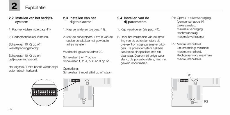
2.2 Instellen van het bedrijfs-systeem
1. Kap verwijderen (zie pag. 41).
2. Codeerschakelaar instellen.
Schakelaar 10 (0) op off: wisselspanningsbedrijf.
Schakelaar 10 (0) op on: gelijkspanningsbedrijf.
Het digitale / Delta bedrijf wordt altijdautomatisch herkend.
2.3 Instellen van het digitale adres
1. Kap verwijderen (zie pag. 41).
2. Met de schakelaars 1 t/m 8 van decodeerschakelaar het gewensteadres instellen.
Voorbeeld: gewenst adres 20.
Schakelaar 3 en 7 op on. Schakelaar 1, 2, 4, 5, 6 en 8 op off.
Opmerking: Schakelaar 9 moet altijd op off staan.
2.4 Instellen van de rij-parameters
1. Kap verwijderen (zie pag. 41).
2. Door het verdraaien van de instel-ling van de potentiometers deovereenkomstige parameter wijzi-gen. De potentiometers hebbenaan beide eindposities een ein-daanslag. Daarom bij enige weer-stand, de potentiometers, niet metgeweld doordraaien.
P1: Optrek- / afremvertraging(gemeenschappelijk)Linkeraanslag: minimale vertraging.Rechteraanslag: maximale vertraging.
P2: MaximumsnelheidLinkeraanslag: minimale maximumsnelheid.Rechteraanslag: maximale maximumsnelheid.
32
2 Exploitatie
P1
P2

2
33
Exploitatie
~
9 0 =
9 0
* afhankelijk van de conventionele instel-ling op wisselstroom (off) of gelijkstroom (on).
Digital Digital Digital
28 – 2 3 – 5 – – 8 – *29 – – 3 – 5 – – 8 – *30 1 – – 4 5 – – 8 – *31 – 2 – 4 5 – – 8 – *32 – – – 4 5 – – 8 – *33 1 – – – 5 – – 8 – *34 – 2 – – 5 – – 8 – *35 – – – – 5 – – 8 – *36 1 – 3 – – 6 – 8 – *37 – 2 3 – – 6 – 8 – *38 – – 3 – – 6 – 8 – *39 1 – – 4 – 6 – 8 – *40 – 2 – 4 – 6 – 8 – *41 – – – 4 – 6 – 8 – *42 1 – – – – 6 – 8 – *43 – 2 – – – 6 – 8 – *44 – – – – – 6 – 8 – *45 1 – 3 – – – – 8 – *46 – 2 3 – – – – 8 – *47 – – 3 – – – – 8 – *48 1 – – 4 – – – 8 – *49 – 2 – 4 – – – 8 – *50 – – – 4 – – – 8 – *51 1 – – – – – – 8 – *52 – 2 – – – – – 8 – *53 – – – – – – – 8 – *54 1 – 3 – 5 – – – – *
55 – 2 3 – 5 – – – – *56 – – 3 – 5 – – – – *57 1 – – 4 5 – – – – *58 – 2 – 4 5 – – – – *59 – – – 4 5 – – – – *60 1 – – – 5 – – – – *61 – 2 – – 5 – – – – *62 – – – – 5 – – – – *63 1 – 3 – – 6 – – – *64 – 2 3 – – 6 – – – *65 – – 3 – – 6 – – – *66 1 – – 4 – 6 – – – *67 – 2 – 4 – 6 – – – *68 – – – 4 – 6 – – – *69 1 – – – – 6 – – – *70 – 2 – – – 6 – – – *71 – – – – – 6 – – – *72 1 – 3 – – – – – – *73 – 2 3 – – – – – – *74 – – 3 – – – – – – *75 1 – – 4 – – – – – *76 – 2 – 4 – – – – – *77 – – – 4 – – – – – *78 1 – – – – – – – – *79 – 2 – – – – – – – *80 1 – 3 – 5 – 7 – – *
01 – 2 3 – 5 – 7 – – *02 – – 3 – 5 – 7 – – *03 1 – – 4 5 – 7 – – *04 – 2 – 4 5 – 7 – – *05 – – – 4 5 – 7 – – *06 1 – – – 5 – 7 – – *07 – 2 – – 5 – 7 – – *08 – – – – 5 – 7 – – *09 1 – 3 – – 6 7 – – *10 – 2 3 – – 6 7 – – *11 – – 3 – – 6 7 – – *12 1 – – 4 – 6 7 – – *13 – 2 – 4 – 6 7 – – *14 – – – 4 – 6 7 – – *15 1 – – – – 6 7 – – *16 – 2 – – – 6 7 – – *17 – – – – – 6 7 – – *18 1 – 3 – – – 7 – – *19 – 2 3 – – – 7 – – *20 – – 3 – – – 7 – – *21 1 – – 4 – – 7 – – *22 – 2 – 4 – – 7 – – *23 – – – 4 – – 7 – – *24 1 – – – – – 7 – – *25 – 2 – – – – 7 – – *26 – – – – – – 7 – – *27 1 – 3 – 5 – – 8 – *
34
2 Exploitatie
2.5 Het bedrijf met de ver-schillende bedrijfssystemen
Dit model is geschikt voor het bedrijf met het Märklin Systems(Mobile Station of Central Station),Märklin Digital (alleen met de Control Unit als centrale), MärklinDelta, wisselstroom (alleen met deMärklin Transformer 32 VA) of gelijk-stroom (rijregelaar met een maximalespanning van +/– 18 Volt=). Schade,ontstaan bij het gebruik op anderebedrijfssystemen, zijn terug te voerenop een niet toegestane bedrijfstoe-stand en vallen daarom niet onder deverantwoordelijkheid van de fabrikantof de fabrieksgarantie. Voor alle daa-ruit ontstane schade is de gebruikerverantwoordelijk.
2.5.1 Het bedrijf met het MobileStation / Central Station
Lees voor het opnemen van dezelocomotief in de locomotieflijst a.u.b.eerst de gebruiksaanwijzing van hetMobile Station of het Central Station.Voor het kiezen van de locomotief uitde databank gebruikt u het artikel-nummer dat u bijv. op de locomotief-verpakking kunt vinden. De volgendeschakelfuncties staan u ter beschik-king:
• Rijrichtingafhankelijke verlichtingaan / uit.
• Cabineverlichting aan / uit.
• Bedrijfsgeluiden (motor 1) aan / uit.
• Geluid van een signaalhoorn aan / uit.
• Bedrijfsgeluiden (motor 2) aan / uit.
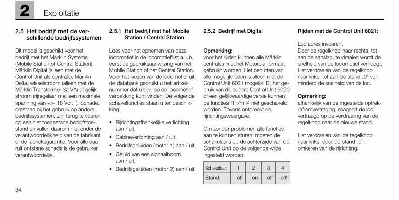
2.5.2 Bedrijf met Digital
Opmerking:voor het rijden kunnen alle Märklincentrales met het Motorola-formaatgebruikt worden. Het benutten vanalle mogelijkheden is alleen met deControl Unit 6021 mogelijk. Bij het ge-bruik van de oudere Central Unit 6020of een gelijkwaardige versie kunnende functies f1 t/m f4 niet geschakeldworden. Tevens ontbreekt derijrichtingsweergave.
Om zonder problemen alle functiesaan te kunnen sturen, moeten deschakelaars op de achterzijde van deControl Unit op de volgende wijzeingesteld worden:
Schakelaar: 1 2 3 4
Stand: off on off off
Rijden met de Control Unit 6021:
Loc adres invoeren.Door de regelknop naar rechts, totaan de aanslag, te draaien wordt desnelheid van de locomotief verhoogt.Het verdraaien van de regelknopnaar links, tot aan de stand „0” ver-minderd de snelheid van de loc.
Opmerking: afhankelijk van de ingestelde optrek-/afremvertraging, reageert de loc vertraagd op de verdraaiing van deregelknop naar de nieuwe stand.
Het verdraaien van de regelknopnaar links, door de stand „0”: omkeren van de rijrichting.
2
35
Exploitatie
Opmerking:de rijrichting wordt bij de Control Unit6021 via de rijrichtingspijlen, naasthet adres, weergegeven.
Pijl naar boven: loc rijdt vooruit.
Pijl naar beneden: loc rijdt achteruit.
Druk op de toets „function”: inschakelen van de verlichting.
Druk op de toets „off”: uitschakelen van de verlichting.
Indrukken van toets “f1“: inschakelen van de cabineverlichting.Door nogmaals op de toets “f1“ tedrukken wordt de cabineverlichtingweer uitgeschakeld.
Indrukken van toets “f2“: bedrijfsgeluiden (motor 1) aan. Door nogmaals op de toets “f2“ tedrukken wordt het geluid weeruitgeschakeld.
Indrukken van toets “f3“: inschakelenvan het geluid van een signaalhoorn.Aansluitend beslist nogmaals op detoets “f3“ drukken om de functieweer uit te schakelen! Anders kan erfunctieverstoring ontstaan.
Indrukken van toets “f4“: bedrijfsgeluiden (motor 2) aan. Door nogmaals op de toets “f4“ tedrukken wordt het geluid weeruitgeschakeld.
2.5.3 Rijden van de loc met Delta
Om met de loc binnen Märklin Deltate kunnen rijden, wordt op de hand-
regelaar Delta-Mobil het ingesteldelocadres gekozen. Door draaien aande rijregelaar vanuit de middenstandnaar rechts rijdt de loc vooruit. Doordraaien aan de rijregelaar venuit demiddenstand naar links rijdt de locachteruit. De rijrichtingafhankelijkeverlichting is constant ingeschakeld.Het maximale uitgangsvermogen vanhet Delta-Station is voldoende omtegelijk met 2 à 3 eenmotorige loco-motieven te laten rijden.
Van de functie „f1“ tot „f4“ is, bij hetDelta gebruik, de functie „f1“ altijdingeschakeld. De andere functies zijnaltijd uitgeschakeld. Hierdoor rijdtdeze loc, op een baan welke aange-stuurd wordt met een Delta-Station,altijd met ingeschakelde cabinever-lichting en zonder dieselgeluid.
2.5.4 Rijden van wisselspanning
In de bedrijfssoort „wisselspanning“kan de loc bijvoorbeeld met een Märklin rijregelaar 6606 in combinatiemet een transformator 6002 geregeldworden. Door de rijregelaar naarrechts te draaien versnelt de loc ennaar links vermindert de snelheid. Alsde rijregelaar door de stand „0” heenverder naar links gedraaid wordt, danwordt de rijrichting omgeschakeld.Het omschakelbevel voor de rijrichtingmag nooit aan een rijdende loc, maaraltijd alleen aan een stilstaande locgegeven worden.
Bij gebruik met wisselspanning is derijrichtingafhankelijke verlichting inge-schakeld. De helderheid van de ver-lichting is afhankelijk van de snelheid.
Van de functie „f1“ tot „f4“ is, bij hetconventionele gebruik, de functie „f1“altijd ingeschakeld. De andere func-ties zijn altijd uitgeschakeld. Hierdoorrijdt deze loc, op een baan welkeaangestuurd wordt met een conven-tionele wisselstroom transformator,altijd met ingeschakelde cabinever-lichting en zonder dieselgeluid.
2.5.5 Rijden van gelijkspanning
Rijregelaars voor gelijkspanning wor-den door Märklin niet voor spoor 1-modellen aangeboden. Geschikte rij-regelaars voor gelijkspanning levereneen maximale spanning van ±18 volt.De wisseling van de rijrichting wordtdoor ompolen bewerksstelligd. Debediening van uw arijregelaar leest uin de handleiding van de fabrikant.
Opmerking: H0-gelijkspanningsappa-raten geven een maximale spanningvan ±12 volt af. De loc bereikt zijnvolle vermogen echter pas bij ±16 volt.H0-gelijkspanningsapparaten zijndaardoor slechts beperkt abruikbaar.
Bij gebruik met gelijkspanning is derijrichtingafhankelijke verlichting inge-schakeld. De helderheid van de ver-lichting is afhankelijk van de snelheid.
Van de functie „f1“ tot „f4“ is, bij hetgelijkstroom gebruik, de functie „f1“altijd ingeschakeld. De andere func-ties zijn altijd uitgeschakeld. Hierdoorrijdt deze loc, op een baan welkeaangestuurd wordt met gelijkstroom,altijd met ingeschakelde cabinever-lichting en zonder dieselgeluid.
2.6 De ingebouwde diesel-geluids-electronica
De geluidselectronica is in de fabriekaangepast aan het loctype. De vol-gende instellingen kunnen door Uveranderd worden:
• Totale geluidsvolume.
• Volume verhouding tussen diesel-geluid en de locfluit.
• Afstelling van de geluidselectronicaaan de op de digitaaldecoderingestelde maximale snelheid.
Bij veranderingen van de maximalesnelheid op de locdecoder (=> In-stellen van de rij-parameters) dientook de geluidselectronica op denieuwe stand afgeregeld te worden.Het veranderen van de optrek- enafrem-vertraging behoeft geen ver-dere afstellingen.
De afstelling van de geluidselectronicadient door het rijden met de loc uit-getest te worden. Voor de besturingmoet de Control Unit / Mobile Station /Central Station gebruikt worden. Aanbevolen wordt de opbouw van eenkleine testbaan (railcirkel of ovaal meteen minimale radius van 1020 mm) of een rollen-proefstand met aange-sloten Control Unit / Mobile Station /Central Station.
Het is aan te bevelen om tijdens deinstelwerkzaamheden de optrekenafremvertraging op de minimalewaarde in te stellen.
Opmerking: Het justeren (instellen)van de geluidselectronica kan door U zelf uitgevoerd worden. Beschadi-gingen die ontstaan door het uitoefe-nen van een te hoge kracht op deinstelpotentiometer (instelschroefje„potmeter") vallen niet onder garantie.
36
2 Exploitatie
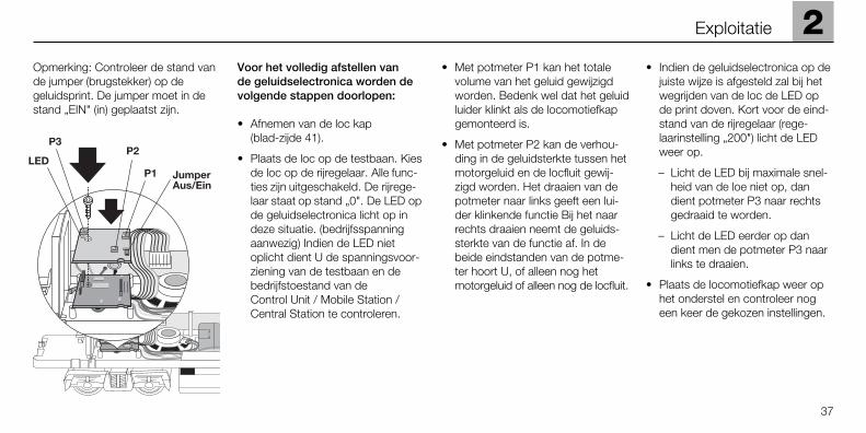
Opmerking: Controleer de stand vande jumper (brugstekker) op degeluidsprint. De jumper moet in destand „EIN" (in) geplaatst zijn.
Voor het volledig afstellen van de geluidselectronica worden devolgende stappen doorlopen:
• Afnemen van de loc kap (blad-zijde 41).
• Plaats de loc op de testbaan. Kiesde loc op de rijregelaar. Alle func-ties zijn uitgeschakeld. De rijrege-laar staat op stand „0". De LED opde geluidselectronica licht op indeze situatie. (bedrijfsspanningaanwezig) Indien de LED nietoplicht dient U de spanningsvoor-ziening van de testbaan en debedrijfstoestand van de Control Unit / Mobile Station /Central Station te controleren.
• Met potmeter P1 kan het totale volume van het geluid gewijzigd worden. Bedenk wel dat het geluidluider klinkt als de locomotiefkapgemonteerd is.
• Met potmeter P2 kan de verhou-ding in de geluidsterkte tussen hetmotorgeluid en de locfluit gewij-zigd worden. Het draaien van depotmeter naar links geeft een lui-der klinkende functie Bij het naarrechts draaien neemt de geluids-sterkte van de functie af. In debeide eindstanden van de potme-ter hoort U, of alleen nog hetmotorgeluid of alleen nog de locfluit.
• Indien de geluidselectronica op dejuiste wijze is afgesteld zal bij hetwegrijden van de loc de LED opde print doven. Kort voor de eind-stand van de rijregelaar (rege-laarinstelling „200") licht de LEDweer op.
– Licht de LED bij maximale snel-heid van de loe niet op, dan dient potmeter P3 naar rechts gedraaid te worden.
– Licht de LED eerder op dan dient men de potmeter P3 naar links te draaien.
• Plaats de locomotiefkap weer ophet onderstel en controleer nogeen keer de gekozen instellingen.
2
37
Exploitatie
2 Exploitatie
Let op de volgende punten bij hetgebruik van de geluidselectronica.
• De geluidselectronica heeft een voedingsspanning nodig van minstens 12 Volt. Als de voedings-spanning onder deze waarde daaltkan het geluid vervormd of zachtklinken of geheel wegvallen. Ookhet bedienen van de functietoetsenbrengt hierin geen verandering.Deze toestand wordt pas beëin-digd na het uitvoeren van eennoodstop (spanning op de railsenkele seconden uitschakelen).Indien deze toestand op eenbepaald baandeel optreedt dientmen de stoomtoevoer naar ditbaandeel te controleren.
• Het opgenomen vermogen van degeluidselectronica bedraagt onge-veer 12 VA. Hierdoor verminderthet maximaal aantal locomotievendie per stroomkring kunnen rijden.
• Indien er continu op conventionelegelijk- of wisselstroom baan gere-den wordt met deze locomotief, ishet raadzaam de jumper op de geluidsprint in de stand "AUS" (uit)te plaatsen.
38

3.1 Anschluss der Gleisanlage
Um Spannungsverluste auf der An-lage zu vermeiden ist immer auf gutesZusammenpassen der Schienenver-bindungslaschen zu achten. Alle3 bis 5 m ist eine neue Stromein-speisung über die Anschlussklemmen5654 empfehlenswert.
3.2 Befahren von Steigungen
Im Gegensatz zum Vorbild könnenmit einer Modellbahn auch größereSteigungen befahren werden. Im Normalfall sollte eine Steigung beimaximal 3 Prozent liegen. Im Extrem-fall sind bei entsprechend einge-schränkter Zugleistung maximal5 Prozent möglich. Der Anfang unddas Ende der Steigung sind auf jedenFall auszurunden. Der Unterschied in der Steigung zwischen zwei
mindestens 300 mm langen Gleis-stücken darf maximal 1 bis 1,5 Prozentbetragen.
3.2 Befahren von gebogenen Gleisen
Diese Lok läuft auf Gleisbögen miteinem Radius von mindestens 1020 mm. Die der Lok beiliegendenZurüstteile (2 Leitungen, Bremsschläu-che, Schraubenkupplungen) könnenbeim Betrieb auf Gleisbögen miteinem Radius von 1020 mm oder1176 mm nicht verwendet werden.
3.1 Connections between the track layout and the transformer
Rail joiners must fit well on the rails of the track to which they are joinedto avoid voltage drop on the layout.We recommend that you install fee-der wires every 3 to 5 meters (10 to16 feet) using the 5654 feeder clips.
3.2 Operating the locomotiveon grades
In contrast to the prototype a locomo-tive on a model railroad can operateup steeper grades. As a general rule agrade should be no steeper than 3%.In extreme situations a maximumgrade of 5% is permissible, keeping inmind that the locomo-tive’s tractiveeffort will be less. The beginning andthe end of the grade must always work
gradually up to maximum grade for theroute. The maximum allowable diffe-rence in grade between two track sec-tions, each with a minimum length of300 mm (11-3/4") is 1 to 1.5 percent.
3.3 Operating the locomotive on curved track
This locomotive can be operated oncurves with a minimum radius op 1,020 mm (40-5/32"). The detailparts included with the locomotive (2 ladders, brake lines, reproductionprototype couplers) cannot be used if the locomotive is to be operated oncurves with a radius of 1,020 mm(40-5/32") or 1,176 mm (46-1/4").
3
39
Betrieb auf der Anlage Operation on a layout

40
3 Exploitation sur réseau Bedrijf op een modelbaan
3.1 Connexion des voiesferrées
Pour éviter des pertes de potentielsur l’installation, il faut veiller à ce queles éclisses de liaison des rails soienttou-jours parfaitement adaptées. Unenou-velle alimentation électrique estconseillée tous les 3 à 5 m au moyendes griffes d’alimentation 5654.
3.2 Franchissement des côtes
Contrairement à l’original, la maquet-te est également en mesure de fran-chir des côtes assez importantes.En temps normal, une côte devraitétre de l’ordre de 3% maximum.A l’extrême limite, 5% sont envisage-ables avec une puis-sance du trainréduite en conséquence. Le début etla fin de la côte doivent en tous casétre arrondis. La différence de pente
entre deux éléments de voie d’aumoins 300 mm de longueur doit étrede 1 à 1,5% maximum.
3.3 Circulation sur des voies courbes
Cette locomotive fonctionne sur desvoies courbes d'un rayon d'au moins1020 mm. Les accessoires joints à lalocomotive (2 échelles, boyaux defrein, attelages à vis) ne peuvent êtreutilisés lors d'une exploitation sur desvoies courbes d'un rayon de 1020 mmou de 1176 mm.
3.1 Aansluiting van de sporen
Om spanningsverlies op de model-baan te voorkomen moeten de rail-lassen altijd goed op elkaar aansluiten.Om de 3 à 5 meter moet de voedingopnieuw op de rails gezet worden.Daarbij zijn de aansluitklemmen 5654aan te raden.
3.2 Berijden van hellingen
In tegenstelling tot het grote voor-beeld kunnen met een modelbaanook grotere hellingen bereden wor-den. Normaal moet een helling maxi-maal 3 procent zijn. In extreme geval-len is maximaal 5 procent mogelijk,maar dan moet reke-ning gehoudenworden met een even-redig verliesaan vermogen. Het begin en heteinde van de helling moeten altijdgerond worden. Het verschil in de
helling tussen twee tenminste300 mm lange railstukken mag maxi-maal 1 à 1,5 procent bedragen.
3.3 Berijden van gebogen rails
Deze loc rijdt in bogen met een straalvan tenminste 1020 mm. De onder-delen die bij de lok meegeleverd zijn(2 ladders, remslangen, schroefkop-pelingen), kunnen bij het rijden inbogen van 1020 mm of 1176 mmniet gebruikt worden.

4
41
Wartung Maintenance Entretien Onderhoud
4.1 Gehäuse abnehmenUm die hervorstehenden Teile aufdem Dach der Lok vor Beschädigungzu schützen, wird die Lok mit derDachseite nach unten in das Oberteilder Verpackung gelegt.
1. Entfernen Sie die Kupplungenvorne und hinten.
2. Entfernen Sie die vier Befestigungs-schrauben an der Unterseite desModelles.
4.1 Removing the bodyTo protect the projecting parts on theroof of the locomotive from damage,the locomotive is to be laid in theupper part of its packaging with theroof upside down.
1. Remove the couplers both frontand rear.
2. Remove the four mounting screwson the underside of the model.
4.1 Enlever le carterAfin de protéger les pièces en sailliesur le toit de la locomotive contre les détério rations, la locomotive estdisposée toit en bas dans la partiesupérieure de l’emballage.
1. Enlever les attelages à l’avant et à l’arrière.
2. Enlevez les quatre vis de fixationsituées sur la face inférieure dumodèle.
4.1 Huis afnemenOm te voorkomen dat de uitstekendedelen op het dak van de lok bescha-digen, wordt de lok met de dakkantnaar beneden in het bovenste gedeeltevan de verpakking gelegd.
1. Verwijder de koppelingen voor enachter.
2. Verwijder de vier bevestigings-schroeven aan de onderzijde vanhet model.
➁
➀
42
4 Wartung Maintenance Entretien Onderhoud
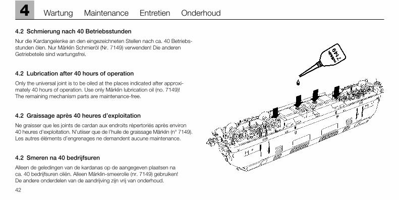
4.2 Schmierung nach 40 Betriebsstunden
Nur die Kardangelenke an den eingezeichneten Stellen nach ca. 40 Betriebs-stunden ölen. Nur Märklin Schmieröl (Nr. 7149) verwenden! Die anderenGetriebeteile sind wartungsfrei.
4.2 Lubrication after 40 hours of operation
Only the universal joint is to be oiled at the places indicated after approxi-mately 40 hours of operation. Use only Märklin lubrication oil (no. 7149)! The remaining mechanism parts are maintenance-free.
4.2 Graissage après 40 heures d’exploitation
Ne graisser que les joints de cardan aux endroits répertoriés après environ 40 heures d’exploitation. N’utiiser que de l’huile de graissage Märklin (n° 7149).Les autres éléments d’engrenages ne demandent aucune maintenance.
4.2 Smeren na 40 bedrijfsuren
Alleen de geledingen van de kardanas op de aangegeven plaatsen na ca. 40 bedrijfsuren oliën. Alleen Märklin-smeerolie (nr. 7149) gebruiken! De andere onderdelen van de aandrijving zijn vrij van onderhoud.
4
43
Wartung Maintenance Entretien Onderhoud
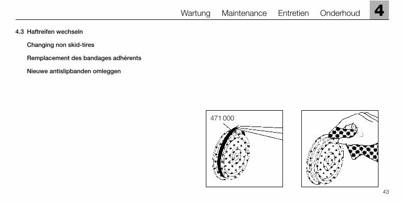
4.3 Haftreifen wechseln
Changing non skid-tires
Remplacement des bandages adhérents
Nieuwe antislipbanden omleggen
471 000

44
4 Wartung Maintenance Entretien Onderhoud
4.4 Schleifer wechseln
Die Schleifer sind zusätzlich angelötet.
4.4 Changing pick-up shoes
The pickup shoes are also soldered in place on the locomotive.
4.4 Remplacement des frotteurs
Les frotteurs sont joints en plus par brasage.
4.4 Nieuwe sleepcontacten aanbrengenDe sleper is apart gesoldeerd.
544 840
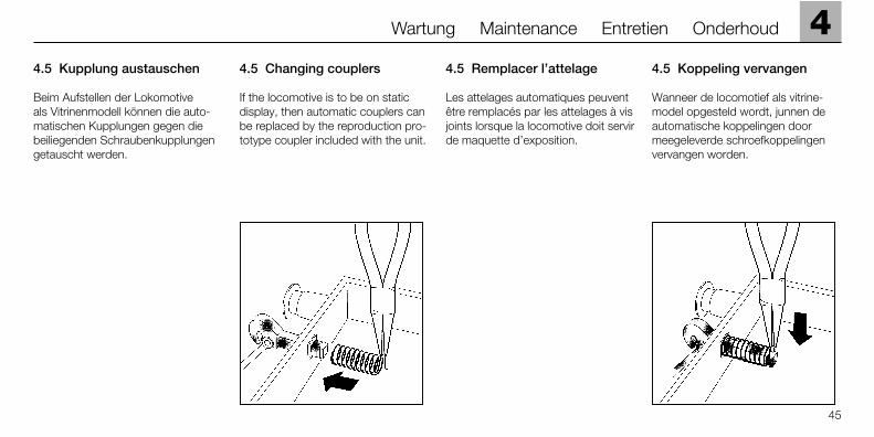
4.5 Kupplung austauschen
Beim Aufstellen der Lokomotive als Vitrinenmodell können die auto-matischen Kupplungen gegen diebeiliegenden Schraubenkupplungengetauscht werden.
4.5 Changing couplers
If the locomotive is to be on staticdisplay, then automatic couplers canbe replaced by the reproduction pro-totype coupler included with the unit.
4.5 Remplacer l’attelage
Les attelages automatiques peuventêtre remplacés par les attelages à visjoints lorsque la locomotive doit servirde maquette d’exposition.
4.5 Koppeling vervangen
Wanneer de locomotief als vitrine-model opgesteld wordt, junnen deautomatische koppelingen door meegeleverde schroefkoppelingenvervangen worden.
4
45
Wartung Maintenance Entretien Onderhoud
4.6 Pflegehinweis
Diese Lok kann auch im Außenbereich eingesetzt werden. Ein Betrieb beischlechten Witterungsbedingungen (Schnee oder Regen) wird nicht empfohlen.Antrieb und Elektronik sind gegen Spritzwasser geschützt. Wasserdurchfahr-ten sind nicht möglich.
Es wird empfohlen, das Modell nach dem Betrieb im Außenbereich auf Ver-schmutzung zu prüfen und gegebenenfalls trocken mit Staubtuch oder Pinselzu reinigen. Nie die Lok unter fließendem Wasser reinigen.
Hinweis: Reinigungsmittel können die Farbgebung oder die Beschriftung derLok angreifen und beschädigen.
4.6 Tips For The Care Of Your Locomotive
This locomotive can also be used outdoors. We do not recommend runningthe locomotive in bad weather (snow or rain). The mechanism and the elec-tronic circuit are protected against spraying water. The locomotive cannot berun through water.
We recommend that you check the locomotive over after running in outdoorsand that you dry it with a cloth or clean in with a brush if necessary. Neverclean the locomotive with running water.
Important: Cleaning fluids can attack the finish and lettering for the locomotiveand damage them.
4.6 Remarque sur l’entretien
Cette locomotive peut également être mise en service à l’air libre. Une utilisa-tion par mauvais temps (neige ou pluie) n’est pas recommandée. Le moteuret l’électronique sont protégés contre les projections d’eau. Des trajets dansl’eau ne sont pas possibles.
Il est recommandé de vérifier l’encrassement du modèle après une utilisation àl’extérieur et, le cas échéant, de nettoyer le modèle à l’aide d’un chiffon douxou un pinceau. Ne jamais nettoyer le modèle au jet d’eau.
Attention: Certains solvants et produits d’entretien peuvent altérer le mar-quage et la peinture du modèle.
4.6 Opmerkingen voor het onderhoud
Deze loc kan ook buiten gebruikt worden. Het gebruik bij slecht weer (sneeuwof regen) is niet aan te raden. Aandrijving en elektronica zijn weliswaar afge-schermd tegen spatwater maar rijden door het water is niet mogelijk.
Het is aan te bevelen het model na het gebruik buiten te controleren op vuilen dit eventueel droog te verwijderen met een stofdoek of een zachte kwast.Nooit de loc onder stromend water reinigen.
Opmerking: reinigingsmiddelen kunnen de lak en de opschriften op de locaantasten en beschadigen.
46
4 Wartung Maintenance Entretien Onderhoud
This device complies with Part 15 of the FCC Rules. Operation is subject to the following two conditions:(1) This device may not cause harmful interference, and(2) this device must accept any interference received, including
interference that may cause undesired operation.
Gebr. Märklin & Cie. GmbHPostfach 8 60D-73008 Göppingenwww.maerklin.com
605 082 08 04 he naÄnderungen vorbehaltenCopyright byGebr. Märklin & Cie. GmbH