Embed Size (px)
Citation preview
Module
14Fire Protection & Life Safety
January 2010
Revised: January 2013
CFRST LEED Volume Program
This Module includes Marriott’s CFRST LEED® Volume Program (LVP) requirements based on the U.S. Green Building Council (USGBC) LEED® for New Construction Version 2.2 rating system. Only participants in the CFRST LVP Program are able to use LEED Version 2.2. The text in “green” with green background and with the “Marriott Spirit to Preserve” logo, applies only to the CFRST LVP Program Version 2.2 requirements.
Design Standards © Marriott International, Inc. January 2010 Revised: January 2013
Revised: January 2013This Module supersedes previous Editions.
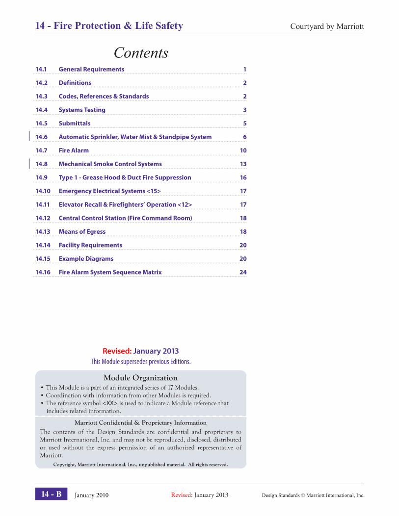
Contents14.1 General Requirements 1
14.2 Definitions 2
14.3 Codes, References & Standards 2
14.4 Systems Testing 3
14.5 Submittals 5
14.6 Automatic Sprinkler, Water Mist & Standpipe System 6
14.7 Fire Alarm 10
14.8 Mechanical Smoke Control Systems 13
14.9 Type 1 - Grease Hood & Duct Fire Suppression 16
14.10 Emergency Electrical Systems <15> 17
14.11 Elevator Recall & Firefighters’ Operation <12> 17
14.12 Central Control Station (Fire Command Room) 18
14.13 Means of Egress 18
14.14 Facility Requirements 20
14.15 Example Diagrams 20
14.16 Fire Alarm System Sequence Matrix 24
Module Organization • This Module is a part of an integrated series of 17 Modules.• Coordination with information from other Modules is required.• The reference symbol <XX> is used to indicate a Module reference that includes related information.
Marriott Confidential & Proprietary InformationThe contents of the Design Standards are confidential and proprietary to Marriott International, Inc. and may not be reproduced, disclosed, distributed or used without the express permission of an authorized representative of Marriott.
Copyright, Marriott International, Inc., unpublished material. All rights reserved.
14 - B
Courtyard by Marriott14 - Fire Protection & Life Safety
January 2010Revised: January 2013
Fire Protection & Life Safety14.1 General Requirements
A. Application:1. Marriott International (MI) Fire Protection and Life
Safety (FLS) Design Standards govern MI owned, managed and franchised Brand properties.
2. The FLS Design Standards include design standards, performance criteria, reference standards and life safety process verifi cation that defi ne a comprehensive fi re protection program. Coordinate requirements with other Modules and in particular <10>, <12> and <15>.
3. Application of these Standards to a specifi c project requires a design analysis. For example, a project’s qualifi cation as either a low-rise or high-rise building will signifi cantly affect the elements of a project’s fi re protection and life safety program.
4. When a MI property is integrated with or interconnected with another building, the building shall provide protection equal to the fi re protection and life safety standards required for the MI property, as defi ned by FLS on a case-by-case evaluation.
B. Systems: Provide the following functional systems in compliance with the listed performance criteria:• Automatic Sprinkler / Standpipe System• Fire Alarm• Mechanical Smoke Control• Type 1 - Grease Hood & Duct Fire Suppression• Emergency Electric Systems• Elevator Recall & Firefi ghters’ Operation• Central Control Station (Fire Command Room)• Means of Egress & Facility Requirements
Design Standards © Marriott International, Inc.
Courtyard by Marriott Fire Protection & Life Safety - 14
14 - 1
Design Standards © Marriott International, Inc. January 2010 Revised: January 2013
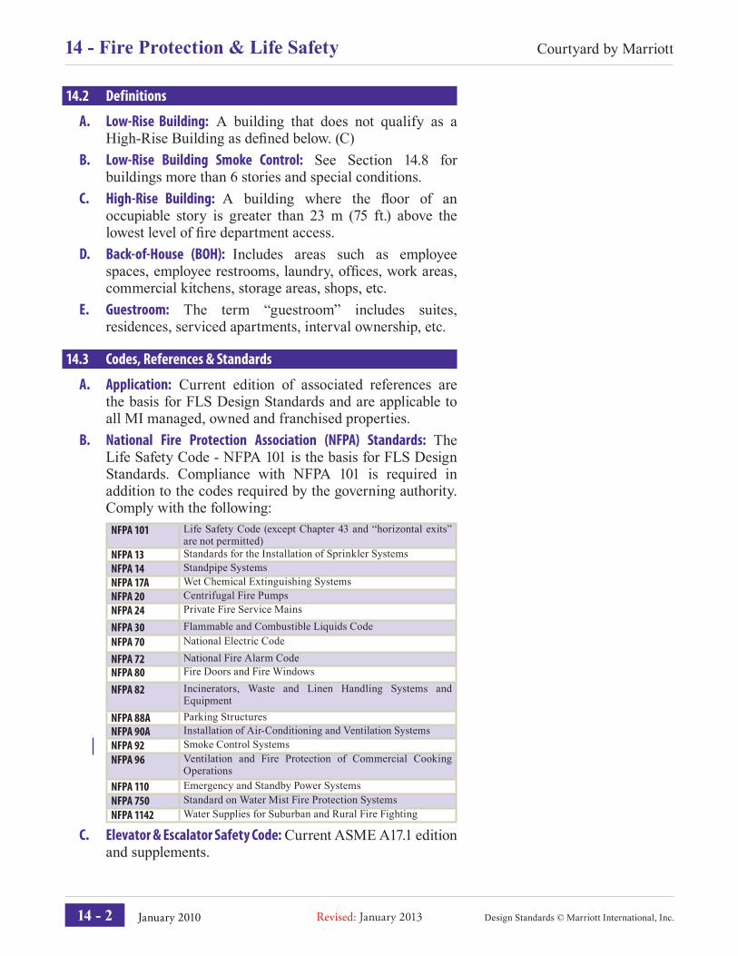
14.2 Definitions
A. Low-Rise Building: A building that does not qualify as a High-Rise Building as defi ned below. (C)
B. Low-Rise Building Smoke Control: See Section 14.8 for buildings more than 6 stories and special conditions.
C. High-Rise Building: A building where the fl oor of an occupiable story is greater than 23 m (75 ft.) above the lowest level of fi re department access.
D. Back-of-House (BOH): Includes areas such as employee spaces, employee restrooms, laundry, offi ces, work areas, commercial kitchens, storage areas, shops, etc.
E. Guestroom: The term “guestroom” includes suites, residences, serviced apartments, interval ownership, etc.
14.3 Codes, References & Standards
A. Application: Current edition of associated references are the basis for FLS Design Standards and are applicable to all MI managed, owned and franchised properties.
B. National Fire Protection Association (NFPA) Standards: The Life Safety Code - NFPA 101 is the basis for FLS Design Standards. Compliance with NFPA 101 is required in addition to the codes required by the governing authority. Comply with the following:
NFPA 101 Life Safety Code (except Chapter 43 and “horizontal exits” are not permitted)
NFPA 13 Standards for the Installation of Sprinkler SystemsNFPA 14 Standpipe SystemsNFPA 17A Wet Chemical Extinguishing SystemsNFPA 20 Centrifugal Fire PumpsNFPA 24 Private Fire Service Mains
NFPA 30 Flammable and Combustible Liquids CodeNFPA 70 National Electric Code
NFPA 72 National Fire Alarm CodeNFPA 80 Fire Doors and Fire Windows
NFPA 82 Incinerators, Waste and Linen Handling Systems and Equipment
NFPA 88A Parking StructuresNFPA 90A Installation of Air-Conditioning and Ventilation SystemsNFPA 92 Smoke Control SystemsNFPA 96 Ventilation and Fire Protection of Commercial Cooking
OperationsNFPA 110 Emergency and Standby Power SystemsNFPA 750 Standard on Water Mist Fire Protection SystemsNFPA 1142 Water Supplies for Suburban and Rural Fire Fighting
C. Elevator & Escalator Safety Code: Current ASME A17.1 edition and supplements.
14 - 2
Courtyard by Marriott14 - Fire Protection & Life Safety
January 2010Revised: January 2013
D. Underwriters Laboratories (UL) Listing: Provide UL listed materials, appliances and equipment.
E. Governing Regulations: Comply with governing laws, codes, regulations and MI Design Standards, including MI requirements that exceed or are more stringent than governing laws, codes and regulations. If governing requirements confl ict with MI’s Design Standards, contact FLS for resolution.
F. Tents & Temporary Structures: Comply with MI’s policy titled “Tents and Temporary Structures” as published on the Marriott Global Source.
14.4 Systems Testing
A. Application: Before a property is occupied, the fi re protection and life safety systems shall be fully operational, contractor tested and acceptance obtained from FLS.In order to obtain MI’s acceptance, the fi re protection and life safety systems shall be operated by the contractor under simulated emergency conditions in the presence of FLS personnel and the contractor shall demonstrate compliance with MI’s Standards.
B. Automatic Sprinkler, Water Mist & Standpipe System (Section 14.6):1. Contractor shall fl ush and pressure test system.2. Contractor shall demonstrate compliance by testing
water fl ow and tamper switches.3. Fire pump shall be tested and certifi ed by the manufacturer.4. Underground mains fl ushed and tested.
C. Fire Alarm (Section 14.7):1. Contractor shall pretest and operate system without
trouble lights exhibited.2. Contractor shall demonstrate compliance by testing all
devices and appliances, auxiliary functions, initiating alarms, and verifying that proper point address and supervision appear on alarm panel.
D. Mechanical Smoke Control (Section 14.8):1. Balance Report: Prior to testing smoke control systems,
HVAC systems shall be contractor tested and balanced. Test and balance report shall be available.
2. Smoke Exhaust: Public area, atrium and guestroom corridor smoke exhaust systems shall be operational and tested to clear “cold smoke” so that exit signs are visible within 10 minutes of activation without smoke migration to other areas.
Design Standards © Marriott International, Inc.
Courtyard by Marriott Fire Protection & Life Safety - 14
14 - 3
Design Standards © Marriott International, Inc. January 2010 Revised: January 2013
3. Stair Pressurization: Test and operate the system, concurrently with the smoke exhaust system, to confi rm design pressures and door opening force.
E. Type 1 - Grease Hood & Duct Fire Suppression (Section 14.9):1. Contractor shall pretest all coordinated components by
activation of hood and duct suppression system control unit.
2. Contractor shall demonstrate compliance by operating initiating devices, activating coordinated alarms, gas, electric and hood supply air fan shut off.
F. Emergency Electrical Systems (Section 14.10):1. Generator shall be operational and tested to
automatically activate upon loss of normal incoming power and to provide standby and emergency service to operate emergency lighting and specifi ed systems.
2. Battery standby power and UPS systems providing emergency power and lighting shall be fully operational.
G. Elevator Recall & Fire� ghters’ Operation (Section 14.11): Elevator Phase 1 Designated Level and Alternate Level Recall and Phase 2 Firefi ghters’ In-Car Operation Features shall be fully tested in compliance with ASME A17.1.
H. Central Control Station (Fire Command Room) (Section 14.12): Panels, indicators, controls and systems shall be operational, tested and accepted.
I. Means of Egress (Section 14.13): Facilities for means of egress shall be operational and unobstructed.
14 - 4
Courtyard by Marriott14 - Fire Protection & Life Safety
January 2010Revised: January 2013
14.5 Submittals
B. Submittal Requirements: Prior to system installation or modifi cation, submit one hard-copy of drawings, plus accompanying materials and documentation of the following for review and acceptance to:1. Marriott Fire Protection & Life Safety:
a. Drawings Scale: Not less than the following:• International Projects: 1:100 scale.• Domestic (U.S. / Canada): ⅛ inch = 1 ft. scale.
b. Floor Plans: Show areas and rooms exiting, exit capacity, occupant load diagrams and fi re resistance ratings.
c. Fire Alarm: System diagrams, shop drawings, equipment product sheets, voltage drop and battery calculations and sequence of operation matrix.
d. Automatic Sprinkler & Standpipe: System shop drawings, hydraulic calculations, and equipment product sheets, fi re pump test curve, and controller and transfer switch equipment sheet.
e. Type 1 Grease Hood & Duct Fire Suppression: <10> Equipment product sheets and drawings indicating cooking equipment, hood and suppression system.
f. Emergency Power: Plans for emergency lighting and exit signs, and information on the emergency power provided.
g. Smoke Control: System shop drawings, sequence of operations, riser diagrams and calculations (space volumes, air changes, make-up and exhaust, fan and equipment fl ow capacities, and locations).
2. Zurich Services Corporation - MI Managed Properties Only:a. Automatic Sprinkler & Standpipe: System shop
drawings, hydraulic calculations and equipment product sheets.
b. Construction Drawings: Set of construction (con-tract) drawings.
C. Mailing Addresses:1. Marriott International, Inc.; Marriott Fire Protection &
Life Safety, Dept. 52/924.36; 10400 Fernwood Road; Bethesda, MD 20817
2. Zurich Services Corporation, Mr. Dale Seemans, 611 Nemours Ln., Woods of Louviers, Newark, DE 19711.
Design Standards © Marriott International, Inc.
Courtyard by Marriott Fire Protection & Life Safety - 14
14 - 5
Design Standards © Marriott International, Inc. January 2010 Revised: January 2013
14.6 Automatic Sprinkler, Water Mist & Standpipe System
A. System Application: Provide MI properties with a complete hydraulically designed combination, automatic sprinkler and standpipe system or HI-FOG water mist system or Minimax Minifog Econ Agua and standpipe system, zoned by fl oor.1. Building Footprint: Sprinkler building areas within
building “footprint”, including canopies required by NFPA 13.
2. Parking Structures: Provide sprinkler protection, unless greater than 50% of perimeter is open to exterior air and not under any portion of the building.
3. Ballrooms & Exhibit Halls: Design the sprinkler system in compliance with Ordinary Hazard Group 1.
4. Ancillary Buildings: Provide sprinkler protection for ancillary buildings that are occupied, have a signifi cant content value or have a signifi cant impact on business interruption if damaged as determined by FLS review. Examples include:• Golf Clubhouse• Golf Maintenance Building• Golf Car Storage Building• Occupied thatched roof buildings• Pool buildings with lockers or F&B
Small structures (less than 9.3 m2 (100 sq. ft.)) located more than 9 m (30 ft.) from other buildings do not require sprinkler protection. Examples include:• Gazebos• Golf Comfort Stations• Golf Weather Protection Stations• Beach Shade Structures
5. Utility Spaces: Provide complete sprinkler protection in electrical, mechanical, telephone and computer rooms.
6. Loading Docks and Truck Bays: Provide sprinkler protection. If subject to freezing, provide dry pipe system.
7. Freezer & Cooler Boxes: Protect with dry type sprinklers supplied from area wet pipe sprinkler system.
8. Guestroom Closets & Pantries: Sprinklers are not required in clothes closets, linen closets and pantries within hotel guestrooms where the area does not exceed 2.2 m2 (24 sq. ft.) and where the least dimension does not exceed 0.9 m (3 ft.) or within Residences where the area does not exceed 1.1 m2 (12 sq. ft.). Closets and pantries with washer, dryer, water heater, mechanical or electrical equipment require sprinklers.
14 - 6
Courtyard by Marriott14 - Fire Protection & Life Safety
January 2010Revised: January 2013
9. Guestroom & Residence Bathrooms: Sprinklers are not required if bathroom is less than 5.10 m2 (55 sq. ft.).
Regardless of bathroom area, sprinklers are required when combustible tubs, or shower and tub surrounds (plastic / fi berglass) enclosures are provided.
10. Coastal Areas: If the project is within 16 km (10 miles) of the coastline, provide exterior galvanized pipe and fi ttings with corrosion resistant sprinklers for wet pipe and dry pipe sprinkler systems in unconditioned spaces.
B. Design Requirements:1. Standards: NFPA 13 (not NFPA 13R), 14, 1142 and 20.2. Water Source: Perform fl ow tests and document. Provide
dependable source of water quantity and pressure from municipal water main or from on site cistern or tanks if municipal water is not available.
3. Safety Factor: Provide a 10% hydraulic safety factor up to a maximum of 0.7 bar (10 psi) for automatic sprinkler system and water mist system.
4. Pressure Reducing Valves: In order to minimize adjustment and maintenance, design system within maximum pressure of 12 bar (175 psi) without use of pressure reducing valves. If pressure reducing valves are necessary, obtain acceptance and specifi c design requirements from FLS.
5. Control Valves: Provide the following:a. Supervisory Signal Initiating Device (tamper switch):
Provide for each control valve.b. Security: Secure valves in the open position with the
applicable methods in the following areas:• Public Areas: Within public view or access, secure
with chains or wire cables and provide keyed-alike locks.
• Back of House: Behind locked doors or access pan-els, under control of the building engineer, secure with plastic or wire seals.
c. Check Valves: Provide check valves at fl oor control valves as required to eliminate false activation of sprinkler waterfl ow alarms on other fl oors.
6. Water Flow Switches: Provide retardant type. Initiate alarm signal between 30 and 60 seconds.
7. CPVC Pipe & Fittings: If provided, install in compliance with manufacturer’s specifi cations. Use chemically compatible materials that contact pipes and fi ttings.
8. Water Reservoir: Where fi re protection and domestic water systems share a common water reservoir (tank, cistern, etc.), locate the domestic water connection at the reservoir above the water level reserved for the fi re system to avoid depleting the fi re system by domestic use.
Design Standards © Marriott International, Inc.
Courtyard by Marriott Fire Protection & Life Safety - 14
14 - 7
Design Standards © Marriott International, Inc. January 2010 Revised: January 2013
9. Fire Pumps: Locate fi re pump drivers, fi re pumps, fi re pump controllers and fi re pump power supplies (normal and standby) above the 100 year fl ood elevation and above the maximum anticipated hurricane storm surge elevations. Comply with NFPA 20 for design and installation.
10. Zoning: Zone each fl oor / story separately at a minimum. See section 14.15 for example diagrams.a. Low-Rise Buildings: Provide each zone with a control
valve, fl ow switch and tamper switch monitored by the fi re alarm system.
b. High-Rise Buildings: Connect guestroom and resi-dential zone sprinkler piping to 2 risers at each fl oor interconnected with a control valve, fl ow switch and tamper switch at each riser.
c. Attic Spaces: Provide dedicated zone for attic spaces, separate from fl oor below.
11. Microbiologically Infl uenced Corrosion (MIC): Refer to NFPA 13 for requirements.
C. Wet Pipe Sprinkler Systems: Provide for habitable spaces such as guestrooms, guestroom corridors, restaurants, ballrooms, meeting rooms, public and back-of-house areas. Route wet pipes in heated spaces.1. Heat tape and insulation is not considered “freeze protected”
and is not acceptable.2. Antifreeze (liquid) systems are not permitted.
D. Dry Pipe Sprinkler Systems: Provide in attic and unheated areas to avoid the possibility of freezing.1. Dry type sprinklers supplied from the wet pipe sprinkler
system may be provided in small unheated areas.2. Antifreeze (liquid) systems are not permitted.3. Use internally galvanized steel pipe throughout the dry
sprinkler system.4. Design for dry valve trip test that provides water to the
remote inspector test and drain assembly within 60 seconds after activation of inspector’s test valve.
5. Provide system with valve, trim, tank mounted compressor with a secured switch, control and test valves, gauges, pressure and high / low air pressure switches and appropriate drains.
E. Inspector’s Test & Drain Assembly: See section 14.15 for example diagrams.1. Drain Pipe: Provide continuous hard pipe (steel or CPVC)
to exterior at ground level in a location where discharge will not damage exterior pavement or landscaping.
2. Access: Visible and readily accessible in back-of-house area or stairwell.
14 - 8
Courtyard by Marriott14 - Fire Protection & Life Safety
January 2010Revised: January 2013
3. Location: Do not locate in fi nished areas (guestroom, guest corridor, etc.).
4. Low Rise Buildings: Locate at farthest (remote) end of zone (not in guestrooms) with continuous hard pipe drain to exterior.
Sprinkler zones with dead end mains or more than one remote end, provide inspector’s tests and drains at each dead end main and remote end.
5. High Rise Buildings:a. Guestroom & Residential Floors: Locate at each riser
(interconnected system), continuous hard pipe drain to exterior.
b. Non-guestroom Floors: With one control valve, locate at remote end of zone, continuous hard pipe drain to exterior.
c. Sprinkler zones with dead end mains or more than one remote end, provide inspector’s tests and drains at each dead end main and remote end.
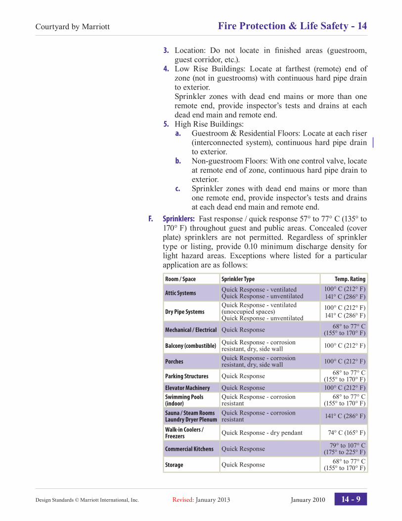
F. Sprinklers: Fast response / quick response 57° to 77° C (135° to 170° F) throughout guest and public areas. Concealed (cover plate) sprinklers are not permitted. Regardless of sprinkler type or listing, provide 0.10 minimum discharge density for light hazard areas. Exceptions where listed for a particular application are as follows:
Room / Space Sprinkler Type Temp. Rating
Attic Systems Quick Response - ventilatedQuick Response - unventilated
100° C (212° F)141° C (286° F)
Dry Pipe SystemsQuick Response - ventilated (unoccupied spaces)Quick Response - unventilated
100° C (212° F)141° C (286° F)
Mechanical / Electrical Quick Response 68° to 77° C(155° to 170° F)
Balcony (combustible) Quick Response - corrosion resistant, dry, side wall 100° C (212° F)
Porches Quick Response - corrosion resistant, dry, side wall 100° C (212° F)
Parking Structures Quick Response 68° to 77° C(155° to 170° F)
Elevator Machinery Quick Response 100° C (212° F)Swimming Pools(indoor)
Quick Response - corrosion resistant
68° to 77° C(155° to 170° F)
Sauna / Steam RoomsLaundry Dryer Plenum
Quick Response - corrosion resistant 141° C (286° F)
Walk-in Coolers / Freezers Quick Response - dry pendant 74° C (165° F)
Commercial Kitchens Quick Response 79° to 107° C(175° to 225° F)
Storage Quick Response 68° to 77° C(155° to 170° F)
Design Standards © Marriott International, Inc.
Courtyard by Marriott Fire Protection & Life Safety - 14
14 - 9
Design Standards © Marriott International, Inc. January 2010 Revised: January 2013
G. Sprinkler Coordination:1. Install sprinklers with the manufacturer’s minimum
allowable projection from the wall or ceiling.2. Coordinate locations of sprinklers at guestrooms and
public areas to avoid location confl icts (such as crown moldings, HVAC grilles, ceiling fans).
3. In corridor ceilings, generally, position sprinklers along centerline of corridor width.
4. In ceilings with acoustical tiles, position sprinklers in center of tiles.
14.7 Fire Alarm
A. Requirements: Provide entire building with a central fi re alarm system from MI’s qualifi ed equipment vendors. See section 14.16 for the Fire Alarm System Sequence Matrix Coordinate with <15>.1. Standard: NFPA 72.2. System: Provide a fully point addressable intelligent
system (all alarm initiating and supervisory devices individually addressable) in all buildings.
3. Supervising Station Service: Provide a remote supervising station service for Marriott properties that receives and records operation signals of the circuits and devices, and notifi es the local fi re department when a general alarm is activated.
4. Campus Style Sites: Provide point addressable intelligent networking that reports to the continuously attended property location.
5. Testing: Provide the following at the Fire Alarm Control Panel (FACP).a. Individual disconnect buttons for testing purposes:
• Audible appliances and visual strobes (sounder base and guestroom hearing impaired strobe shall function upon guestroom smoke sensor activation)
• Door hold open mechanisms• Elevator recall• Air handlers
b. Alarm sensitivity testing capability at FACP.6. Exterior & Unconditioned Areas: Provide NEMA 4X
rated devices and appliances (weatherproof, corrosion resistant) listed for exterior exposure.
14 - 10
Courtyard by Marriott14 - Fire Protection & Life Safety
January 2010Revised: January 2013
B. System Smoke Sensors (Detectors):1. Guestrooms, Suite Rooms and other Sleeping Units: Provide
24 Volt system smoke sensors with sounder bases to meet the following:a. Photoelectric type sensor.b. Sounder Base: Provide minimum audible alarm of
85 dBA at 3 m (10 ft.); minimum of 75 dBA “at the pillow”.
c. Activation of room system smoke sensor to immediately and automatically sound an alarm (three pulse temporal pattern) within the room of incident and annunciate as a supervisory signal.
d. System smoke sensor normal and emergency power is provided by the FACP.
e. In suites and other mixed sleeping spaces, provide the following:• System smoke sensors in each separate sleeping
room, living rooms convertible to sleeping and areas providing access to the corridor doorway.
• Simultaneously activate multiple smoke sensor sounder bases located within the same suite or unit.
f. To minimize unwanted alarms, avoid locating smoke sensors near the kitchen or bathrooms.
g. Locate smoke sensors at the highest ceiling area in the room.
2. Public Areas, Corridor & BOH Areas: Provide system smoke sensors where:a. Required by governing code.b. Smoke exhaust is required in compliance with the
other requirements of this Module.3. Duct System Smoke Sensors: Provide duct system smoke
sensors as required by NFPA 101 Life Safety Code. Provide remote test switch and indicator light accessible from fl oor level.
C. Carbon Monoxide (CO) Detectors: Install CO detectors with sounders. Connect to the FACP and annunciate as a supervisory signal.1. General: Provide in rooms and areas containing fuel
burning appliances and equipment.2. Fireplaces: Provide detector in areas containing fuel
burning (including wood) fi replaces.D. Manual Pull Stations: At Reception Desk only, unless required
in other locations by applicable codes.E. Fire� ghter Communication Systems: Comply with governing
code requirements.
Design Standards © Marriott International, Inc.
Courtyard by Marriott Fire Protection & Life Safety - 14
14 - 11
Design Standards © Marriott International, Inc. January 2010 Revised: January 2013
F. Alarm Noti� cation Appliances: Provide audible notifi cation appliances (speakers, mini-horns, horns, or sounder bases of system smoke sensors listed for general and local evacuation) and visual notifi cation strobe lights in locations according to the following:1. Guestroom, Suite Rooms & other Sleeping Units: Provide
audible appliances in each sleeping room. In properties with separate multiple sleeping spaces, such as suites and apartments, provide in each sleeping room.
2. Hearing Accessible Designated Guestrooms, Suites, or Residential Units: Provide audible alarm appliances and visual alarm strobes.a. Arrange strobes to fl ash in each room or area,
within direct line of sight from bed pillows, and bathroom when the following occurs:• System smoke sensors and (CO) detectors in
rooms or units activate.• Building fi re alarm notifi cation alarms activate.
b. Strobe Light Rating:• 177 candela - within 61 cm (24 inch) from the
ceiling.• 110 candela - more than 61 cm (24 inch) from
the ceiling.3. Public Areas, Corridors & BOH: Provide audible and
visual notifi cation appliances.G. Emergency Occupant Noti� cation:
1. Low-Rise Buildings: Automatic alert tone (three pulse temporal pattern).
2. High-Rise Buildings & Assembly Spaces Over 300 Occupants: Continuous cycle alert tone and automatic prerecorded voice message with manual voice communication override.
H. Annunciator: Provide point address to indicate fl oor, specifi c location, device and type of alarm. Provide annunciators in areas monitored 24 hours by property employees (Security, AYS, PABX room, Reception Desk) in locations acceptable to Marriott and governing authority.
I. Door Hold Open Mechanism: Automatically release doors in affected zone when an alarm is activated. See “Means of Egress” section in this Module.
14 - 12
Courtyard by Marriott14 - Fire Protection & Life Safety
January 2010Revised: January 2013
14.8 Mechanical Smoke Control Systems
A. Application: Provide an engineered mechanical smoke control system including public area smoke exhaust and stair pressurization for egress stairs. Coordinate smoke control system requirements with Module <15>.
B. Systems & Locations: Design for the following mechanical smoke control systems:• Smoke exhaust - public areas• Smoke exhaust - guestroom corridors• Pressurization - egress stairs (including transfer enclosures)
C. Standards: NFPA 92D. Building Con� guration:
1. Low-Rise Buildings: Mechanical smoke control is required in buildings more than 6 stories, regardless of height. Smoke control may also be required in other low-rise buildings if FLS judges that fi re department access is limited or exiting is not adequate.
2. High-Rise Buildings: Mechanical smoke control is required.
3. Atrium: Consult FLS for atrium smoke control requirements.
E. Acceptance: Obtain FLS acceptance for entire smoke control systems design, sequences of operation and air quantities.
F. System Con� gurations:1. Zones: Each space is treated as an individual fi re /
smoke zone.2. Capacity: In spaces requiring smoke exhaust, provide a
minimum of 8 air changes per hour.a. In larger spaces such as atriums and exhibit halls,
increase the air change rates.b. Consult with FLS on project specifi c criteria.
3. Makeup Air: Provide makeup air for each smoke exhaust zone.
4. Ducted System: Provide hard ducted smoke exhaust from each smoke zone. Return air plenums and slot diffusers are not permitted for smoke exhaust systems.
5. Dampers: Provide motor operated, low leakage, automatic reset, dampers for smoke exhaust systems. Manual reset dampers are not allowed.
G. Public Areas: Provide hard ducted, mechanical smoke exhaust from each smoke zone in lobby, atriums, restaurants, pre-function areas, ballrooms, meeting rooms greater than 32.5 m² (350 sq. ft.), exhibition halls and other assembly occupancies.
Design Standards © Marriott International, Inc.
Courtyard by Marriott Fire Protection & Life Safety - 14
14 - 13
Design Standards © Marriott International, Inc. January 2010 Revised: January 2013
Sequence of Operation - Public Areas:1. Signal: The smoke exhaust system is initiated automatically
by a signal from the fi re alarm panel when an area smoke sensor is activated.
2. Smoke Exhaust Fan: Discharge damper fully opens. The fan starts and provides 100% exhaust to exterior.
3. HVAC System - Confi ned Areas: In zones where makeup air is not readily available (ballroom, meeting room, etc.), the return damper of the HVAC system serving the smoke zone closes and the supply fan reduces to 50% outside air.
4. Other Zones: Supply, return and exhaust fans for HVAC systems in other zones remain in normal operating mode.
H. Guestroom Corridors: Centrally locate on each fl oor a dedicated mechanical smoke exhaust riser with normally closed smoke dampers on each fl oor.1. Capacity: Size each roof mounted smoke exhaust fan to
simultaneously serve corridors of three fl oors.2. Distance: 30 m (100 ft.) maximum horizontal distance
between supply and exhaust risers. This arrangement ensures smoke moves in direction opposite of guests traveling to a means of egress.
3. Activation: Activate automatically by area smoke sensors and by fl oor water fl ow switches (independent of each other).
4. Zones: If smoke doors divide corridor into two or more sections, provide independent exhaust inlet in each section.
5. Sequence of Operation - Guestroom Corridors:a. Smoke exhaust system is initiated by a signal through
the fi re alarm panel from either a corridor smoke sen-sor or sprinkler fl ow switch.
b. Upon activation, normally closed smoke exhaust damper on fl oor of incidence opens and dampers are closed on remaining non-incidence fl oors.
c. Discharge damper fully opens and the smoke exhaust fan starts.
d. Guest corridor and guestroom DAOS (Dedicated Outside Air System) continues to operate in normal mode.
e. If applicable, secondary guest corridor pressuriza-tion fans start (sized for a minimum capacity of 6 air changes per hour supply air to each fl oor) and guest corridor and guestroom DAOS is turned off.
f. Guest Tower Area: Exhaust fans, including those serving vending rooms and electrical rooms, continue to operate in normal mode.
14 - 14
Courtyard by Marriott14 - Fire Protection & Life Safety
January 2010Revised: January 2013
I. Stair Pressurization: Automatically activate and mechanically pressurize egress stair enclosures in compliance with NFPA 101.1. System Confi gurations: The following are approximate
stair enclosure heights and typical design arrangements for fans and ducts:a. 10 Stories: Single induction pointb. 10 to 20 Stories: One fan at top and one at bottomc. 20 or More Stories: One or more supply fans ducted
through stair with supply registers located every third fl oor.
2. Fan:a. Type: Provide fan with variable frequency drive con-
trolled by multiple pressure differential sensors by means of a discriminator.
b. Capacity: Size fans to provide a balanced 470 l/s (1,000 cfm) per door.
c. Supply Damper: Motor operated, low leakage3. Design Pressure: Provide pressure differential sensors
to measure the difference across doors of not less than 2.5 N m2 (0.05 inch w.c.).
4. Doors: 13.50 kg (30 lbs.) maximum opening force across doors into egress stairs.
5. Sequence of Operation - Stair Pressurization:a. Initiation: System is initiated by a signal from the fi re
alarm panel due to activation of either a public space (excluding guestrooms) smoke sensor or sprinkler fl ow switch.
b. Dedicated Smoke Sensor: In areas without full area smoke detection, provide smoke sensor within 3 m (10 ft.) of stair enclosure exit doors to activate system.
c. Supply Damper: Upon activation, supply damper fully opens and stairwell pressurization fans start.
J. Back-of-House Areas: Provide smoke control only where required by governing authorities having jurisdiction.
K. Smoke Control Panel: Provide a smoke control panel for manual control of equipment that is part of the smoke control system with Hand-Off-Automatic (HOA) and pilot lights (one switch and lights for each AHU, fan and damper).1. Location: Position the smoke control panel at the location
of the main fi re alarm panel.2. Power: Provide internal power source for manual operation
of all equipment. Provide voltage same as fi re alarm system.3. ‘Hand’ Position: Manually activates all equipment into
smoke control mode.
Design Standards © Marriott International, Inc.
Courtyard by Marriott Fire Protection & Life Safety - 14
14 - 15
Design Standards © Marriott International, Inc. January 2010 Revised: January 2013
4. ‘Off’ Position: Shuts down the equipment and returns all dampers to their normal mode.
5. ‘Automatic’ Position: Allows system to operate in normal building mode, or in smoke control mode upon receipt of a signal from the fi re alarm panel.
L. Supply Duct Smoke Sensors:1. Location: Provide downstream of air handling units
over 945 l/s (2,000 cfm).2. Operation: Smoke sensor shuts down AHU upon
sensing smoke and annunciates at fi re alarm panel, but does not activate smoke exhaust system.
M. Fire Alarm Matrix: See “Fire Alarm System Sequence Matrix” at end of this Module for sequence of operation.
14.9 Type 1 - Grease Hood & Duct Fire Suppression
A. Application: Provide fi re suppression system for hoods and ducts at food production cooking locations that produce grease laden vapors. Coordinate fi re suppression system function and design with Modules <10>, <15B> and <15C>.
B. Suppression System: Provide Ansul “Piranha” dual agent suppression system.
C. Sequence of Operation: The hood and duct fi re suppression system control units initiate the following:1. Alarm Signal: Send fi re alarm signal to FACP.2. Gas: Automatically activate solenoid to turn off gas to
affected cooking lines.3. Power: Automatically turn off power to cooking
appliances, lighting and hood makeup air handler, except exhaust fan continues to operate.
14 - 16
Courtyard by Marriott14 - Fire Protection & Life Safety
January 2010Revised: January 2013
14.10 Emergency Electrical Systems <15>
A. Standards: NFPA 110, NFPA 70 (NEC), NFPA 101B. System Requirements: Provide standby power for emergency
power and lighting in the event of loss of normal incoming electrical service.• Transfer from one power source to another must take no
longer than 10 seconds.• See Module <15> for backup operational power loads to
maintain property operations.C. Emergency Lighting: Provide emergency lighting for code
required egress, property operations and safety, as follows:• Exit signs• Egress paths and stairs• Exterior exit door discharge• Meeting Rooms, Ballrooms, Exhibit Halls• Restaurants, Lounges• Public stairs and steps• Telephone Equipment Room• Mechanical, electrical and elevator rooms• Public toilets• Fire Pump / Sprinkler Riser Room• Kitchens (commercial F&B preparation areas)• Laundry• Reception Desk• Employee Cafeteria / Breakroom• Employees lockers and toilets• Fitness Center• Engineering / Maintenance Offi ce• Administrative Offi ce area• PABX & AYS Room• Security Offi ce• Parking Structure• Indoor Pool room• Spa Treatment Rooms• Fire Command Room (high-rise building)
14.11 Elevator Recall & Firefighters’ Operation <12>
A. ASME A17.1: Provide Elevator Phase 1 Designated Level and Alternate Level Recall, Shunt Trip and Phase 2 Firefi ghters’ In-Car Operations in compliance with ASME A17.1; see Module <12>.
Design Standards © Marriott International, Inc.
Courtyard by Marriott Fire Protection & Life Safety - 14
14 - 17
Design Standards © Marriott International, Inc. January 2010 Revised: January 2013
14.12 Central Control Station (Fire Command Room)
A. High-Rise Buildings: Provide at a location acceptable to the governing authority. <15>
14.13 Means of Egress
A. Standards: Comply with NFPA 101, The Life Safety Code, except “horizontal exits” are not permitted.
B. Guestroom Areas Corridors: <7> Comply with the following:1. Exits: 2 or more remote exits2. Dead-End Corridor Limit: 15.24 m (50 ft.) 3. Common Path Limit: 15.24 m (50 ft.)
C. Assembly Spaces: <3> <6>1. Occupant Load Factors:
a. Ballrooms, Meeting Rooms & Exhibit Halls: 0.65 m² (7 sq. ft.) per occupant
b. Restaurant, Lounges & Boardrooms: 1.4 m² (15 sq. ft.) per occupant
2. Design Requirements:a. Dead-End Corridor Limit: 6.10 m (20 ft.)b. Common Path Limit: 6.10 m (20 ft.)c. Panic & Fire Exit Hardware: Provide hardware on
assembly occupancy doors where occupant loads are greater than 100 persons and on doors in the paths of travel to the exterior exit discharge.
d. Remote Exits: Occupant loads greater than 50 per-sons, using the above occupant load factors, requires two or more remote exits. Distance between the nearest edges of remote exits is a minimum of one third the greatest diagonal dimension of the space.
e. Door Hold Open Mechanism: On entry doors (not BOH service doors) to assembly rooms <6> greater than 32.5 m2 (350 sq. ft.), provide electro-magnetic door hold open mechanism connected to the fi re alarm system and electrical service <15> to hold doors open and to automatically release doors when an alarm is activated.
f. Operable Partitions: Doors in operable partitions do not qualify as exits.
g. Commercial Kitchen Areas: Egress paths through Kitchens do not qualify as exits.
h. Banquet Chairs: Provide a fastening device on banquet chairs to connect chairs to each other in rows to prevent individual chair displacement from blocking rows and aisles during emergency egress from assembly occupancies with more than 200 persons.
14 - 18
Courtyard by Marriott14 - Fire Protection & Life Safety
January 2010Revised: January 2013
D. Egress Capacity:1. Stairways: 7.6 mm (0.3 inch) width per person2. Doors, Level Components & Ramps: 5 mm (0.2 inch)
width per personE. Multi-Use Exits: Avoid sharing stairs and exit corridors
with other properties (offi ce, retail, residence, etc.). If unavoidable, submit and obtain acceptance from FLS of alternate facilities that safeguard the property operational and security integrity. <1>
F. Exterior Exit Path: Provide the required width for the exit capacity but not less than 90 cm (3 ft.), hard surfaced walkway leading to a public way.
G. Evacuation Signage: <GR> Provide in guestrooms <7> and other rooms and spaces as directed by FLS.
H. Exit Discharge: Discharge one half of all exits directly to the building exterior.
I. Doors: Do not lock stair doors and exit doors from either side. Doors to the exterior must allow for exit access but may be designed to prevent entry from the exterior.
J. Stair Handrails: At a minimum, provide handrails on both sides of stairways. See Module <16>.
Design Standards © Marriott International, Inc.
Courtyard by Marriott Fire Protection & Life Safety - 14
14 - 19
Design Standards © Marriott International, Inc. January 2010 Revised: January 2013
14.14 Facility Requirements
A. Fire Resistance Ratings: Fire resistance ratings of walls, doors, shafts, stair enclosures, fl oor / ceiling assemblies and fl ammability ratings of furnishing, carpeting, curtains and wall fi nishes shall comply with NFPA 101.
B. Operable Windows: <16> Where operable windows are utilized, provide windows with window manufacturer’s safety stops integral with window frame to restrict opening to 10 cm (4 inch) maximum width.1. See governing code for other restrictions.2. Provide with manufacturer’s “key” for maintenance.
C. Fireplaces: Obtain FLS acceptance of custom fi replaces.D. Linen & Trash Chutes: <7> Comply with NFPA 82, NFPA
101 and NFPA 13.1. Chute Vent: Provide (full size) a minimum of 90 cm
(3 ft.) above the roof line.2. Construction: Provide metal, prefabricated,
manufactured chute within a fi re rated shaft.3. Loading Door: Protect chute openings with a fi re rated
loading door, located within a service opening room (vestibule).
4. Room Enclosure: Construct the service opening room (vestibule) with fi re rated enclosure and door.
5. Sprinkler: Install a sprinkler above the top service opening of the chute, above the lowest service opening, and above service openings at alternate levels in buildings over two stories in height.
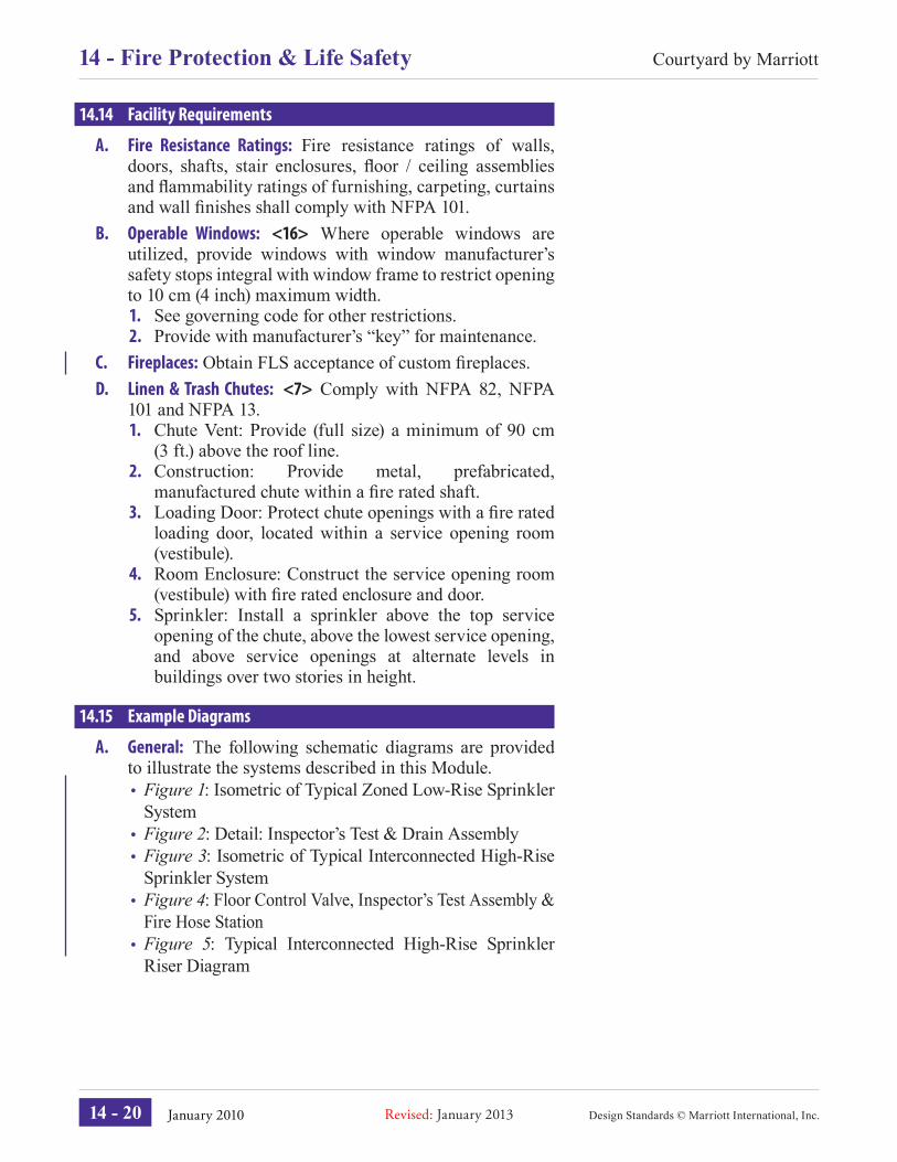
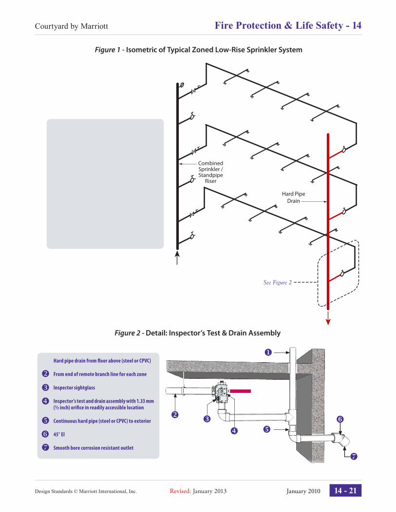
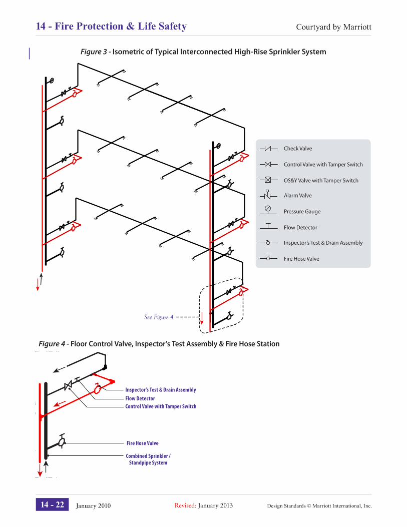
14.15 Example Diagrams
A. General: The following schematic diagrams are provided to illustrate the systems described in this Module.• Figure 1: Isometric of Typical Zoned Low-Rise Sprinkler
System• Figure 2: Detail: Inspector’s Test & Drain Assembly• Figure 3: Isometric of Typical Interconnected High-Rise
Sprinkler System• Figure 4: Floor Control Valve, Inspector’s Test Assembly &
Fire Hose Station• Figure 5: Typical Interconnected High-Rise Sprinkler
Riser Diagram
14 - 20
Courtyard by Marriott14 - Fire Protection & Life Safety
January 2010Revised: January 2013
Figure 1 - Isometric of Typical Zoned Low-Rise Sprinkler System
Combined Sprinkler / Standpipe
Riser
Hard Pipe Drain
See Figure 2
Inspector’s Test & Drain Assembly
Fire Hose Valve
Alarm Valve
Pressure Gauge
Flow Detector
Check Valve
Control Valve with Tamper Switch
OS&Y Valve with Tamper Switch
Figure 2 - Detail: Inspector’s Test & Drain Assembly
Hard pipe drain from � oor above (steel or CPVC)
From end of remote branch line for each zone
Inspector sightglass
Inspector’s test and drain assembly with 1.33 mm (½ inch) ori� ce in readily accessible location
Continuous hard pipe (steel or CPVC) to exterior
45° El
Smooth bore corrosion resistant outlet
Design Standards © Marriott International, Inc.
Courtyard by Marriott Fire Protection & Life Safety - 14
14 - 21
Design Standards © Marriott International, Inc. January 2010 Revised: January 2013
Figure 4 - Floor Control Valve, Inspector’s Test Assembly & Fire Hose Station
Flow DetectorControl Valve with Tamper Switch
Fire Hose Valve
Combined Sprinkler / Standpipe System
Inspector’s Test & Drain Assembly
Figure 3 - Isometric of Typical Interconnected High-Rise Sprinkler System
See Figure 4
Inspector’s Test & Drain Assembly
Fire Hose Valve
Alarm Valve
Pressure Gauge
Flow Detector
Check Valve
Control Valve with Tamper Switch
OS&Y Valve with Tamper Switch
14 - 22
Courtyard by Marriott14 - Fire Protection & Life Safety
January 2010Revised: January 2013
Figure 5 - Typical Interconnected High-Rise Sprinkler Riser Diagram
Roof Level
10th Level
9th Level
8th Level
7th Level
6th Level
5th Level
4th Level
3rd Level
2nd Level
1st Level
Fire Dept. Connection
Looped Connection (Typical)
CombinationSprinkler / Standpipe Riser
Roof HoseConnection
Test Header Fire Pump
Dependable Water Supply
Pump By-Pass
Jockey Pump
Drain Drain
Alarm Valve
Pressure Gauge
Flow Switch
Check Valve
Control Valve with Tamper Switch
OS&Y Valve with Tamper Switch
Inspector’s Test & Drain Assembly
Fire Hose Valve
Design Standards © Marriott International, Inc.
Courtyard by Marriott Fire Protection & Life Safety - 14
14 - 23
Design Standards © Marriott International, Inc. January 2010 Revised: January 2013
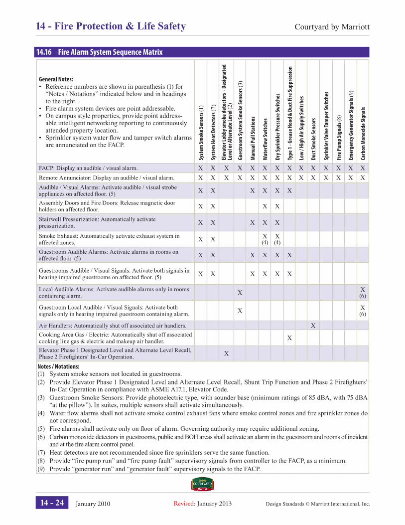
14.16 Fire Alarm System Sequence Matrix
General Notes:• Reference numbers are shown in parenthesis (1) for
“Notes / Notations” indicated below and in headings to the right.
• Fire alarm system devices are point addressable.• On campus style properties, provide point address-
able intelligent networking reporting to continuously attended property location.
• Sprinkler system water fl ow and tamper switch alarms are annunciated on the FACP.
Syst
em Sm
oke S
enso
rs (1
)
Syst
em H
eat D
etec
tors
(7)
Elev
ator
Lobb
y sm
oke d
etec
tors
- De
signa
ted
Leve
l or A
ltern
ate L
evel
(2)
Gues
troo
m Sy
stem
Smok
e Sen
sors
(3)
Man
ual P
ull S
tatio
ns
Wat
er� o
w Sw
itche
s
Dry S
prin
kler
Pre
ssur
e Sw
itche
s
Type
1 - G
reas
e Hoo
d &
Duct
Fire
Supp
ress
ion
Low
/ Hig
h Ai
r Sup
ply S
witc
hes
Duct
Smok
e Sen
sors
Sprin
kler
Valv
e Tam
per S
witc
hes
Fire
Pum
p Si
gnal
s (8)
Emer
genc
y Gen
erat
or Si
gnal
s (9)
Carb
on M
onox
ide S
igna
ls
FACP: Display an audible / visual alarm. X X X X X X X X X X X X X XRemote Annunciator: Display an audible / visual alarm. X X X X X X X X X X X X X XAudible / Visual Alarms: Activate audible / visual strobe appliances on affected fl oor. (5) X X X X X X
Assembly Doors and Fire Doors: Release magnetic door holders on affected fl oor. X X X X
Stairwell Pressurization: Automatically activate pressurization. X X X X X
Smoke Exhaust: Automatically activate exhaust system in affected zones. X X X
(4)X (4)
Guestroom Audible Alarms: Activate alarms in rooms on affected fl oor. (5) X X X X X X
Guestrooms Audible / Visual Signals: Activate both signals in hearing impaired guestrooms on affected fl oor. (5) X X X X X X
Local Audible Alarms: Activate audible alarms only in rooms containing alarm. X X
(6)
Guestroom Local Audible / Visual Signals: Activate both signals only in hearing impaired guestroom containing alarm. X X
(6)
Air Handlers: Automatically shut off associated air handlers. XCooking Area Gas / Electric: Automatically shut off associated cooking line gas & electric and makeup air handler. X
Elevator Phase 1 Designated Level and Alternate Level Recall, Phase 2 Firefi ghters’ In-Car Operation. X
Notes / Notations:(1) System smoke sensors not located in guestrooms.(2) Provide Elevator Phase 1 Designated Level and Alternate Level Recall, Shunt Trip Function and Phase 2 Firefi ghters’
In-Car Operation in compliance with ASME A17.1, Elevator Code.(3) Guestroom Smoke Sensors: Provide photoelectric type, with sounder base (minimum ratings of 85 dBA, with 75 dBA
“at the pillow”). In suites, multiple sensors shall activate simultaneously.(4) Water fl ow alarms shall not activate smoke control exhaust fans where smoke control zones and fi re sprinkler zones do
not correspond.(5) Fire alarms shall activate only on fl oor of alarm. Governing authority may require additional zoning.(6) Carbon monoxide detectors in guestrooms, public and BOH areas shall activate an alarm in the guestroom and rooms of incident
and at the fi re alarm control panel.(7) Heat detectors are not recommended since fi re sprinklers serve the same function.(8) Provide “fi re pump run” and “fi re pump fault” supervisory signals from controller to the FACP, as a minimum.(9) Provide “generator run” and “generator fault” supervisory signals to the FACP.
14 - 24
Courtyard by Marriott14 - Fire Protection & Life Safety