Embed Size (px)
Citation preview

Montering av väggbeslag på Brustor B-25 och B-25 Elite.
De breda beslagen måste sitta bakom arminfästningarna i kassetten. Arminfästningarna är markerade med svarta tuschstreck bak på markisen. Om ett smalt beslaget finns med, sätts det i mitten på markisen. Markisen går sönder och ingen garanti gäller om detta inte beaktas.
Montering av takbeslag på Brustor B-25 och B-25 Elite.
De breda beslagen måste sitta exakt bakom arminfästningarna i kassetten. Arminfästningarna är markerade med svarta tuschstreck bak på markisen. Av de smala beslagen sätts ett i varje ända och ett i mitten på markisen. Markisen går sönder och ingen garanti gäller om detta inte beaktas.
DEALER SERVIC E MAN UAL © B RUSTOR LOU R DESSTRAAT 84 B-8940 GELUWE T. +32 (0) 56 .53 .18 .53 F. +32 (0) 56 .53 .18 .20 / 9
DEALER SERVICE MANUAL
2,05-3,50 3,51-4,00 4,01-5,50 5,51-6,00 / 3 arms 5,51-6,50 / 2 arms 6,51-7,00 7,01-8,00 8,01-1100 11,01-12,00 12,01-13,00 12,01-13,00
1,50 2x300 2x300 2x5001x100
2x5001x300
2x5001x100
2x5001x3001x100
2x3001x1000
2x5001x10002x100
2x5001x10002x100
- 2x5002x10003x300
2,00 2x300 2x300 2x5001x100
2x5001x300
2x5001x100
2x5001x3001x100
2x3001x1000
2x5001x10002x100
2x5001x10002x100
- 2x5002x10003x300
2,50 2x300 2x300 2x5001x100
2x5001x300
2x5001x300
2x5001x3001x100
2x3001x1000
2x5001x10002x100
- 2x5001x10002x300
2x5002x10003x300
3,00 - 2x300 2x5001x100
2x5001x300
2x5001x300
2x5001x3001x100
2x3001x1000
2x5001x10002x100
- 2x5001x10002x300
2x5002x10003x300
3,50 - 2x5001x100
2x5001x100
2x5001x300
2x5001x300
2x5001x3001x100
- 2x5001x10002x100
- - -
3,75 - 2x5001x100
2x5001x100
2x5001x300
2x5001x300
2x5001x3001x100
- 2x5001x10002x100
- - -
09.V1 ENG
INSTALLATION INSTRUCTIONS B25 - B28 (ELITE) / B26 ELITE / B27Read these installation instructions carefully . a correct functioning needs a correct installation . no guarantee will be allowed for wrong installation .
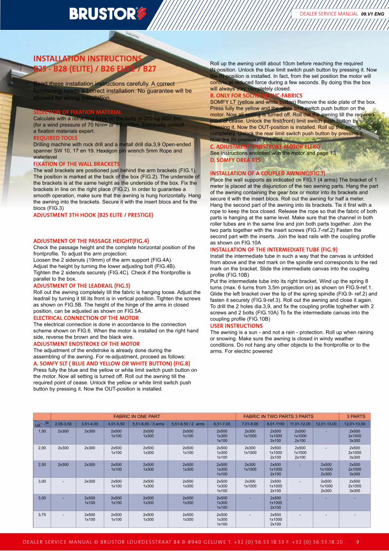
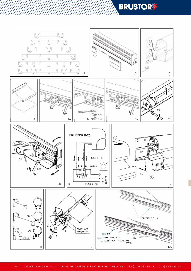
SELECTION Of fIXATION MATERIALCalculate with a retracting force on the bolts of 370 kg (830 lbs)(for a wind pressure of 70 N/m≈ or 1.5 lbf/ft≈). Eventually consulta fixation materials expert .REQUIRED TOOLSDrilling machine with rock drill and a metall drill dia .3,9 Open-ended spanner SW 10, 17 en 19 . Hexagon pin wrench 5mm Rope and waterlevel fIXATION Of ThE WALL BRACKETSThe wall brackets are positioned just behind the arm brackets (FIG .1) . The position is marked at the back of the box (FIG .2) . The underside of the brackets is at the same height as the underside of the box . Fix the brackets in line on the right place (FIG .2) . In order to guarantee a smooth operation, make sure that the awning is hung horizontally . Hang the awning into the brackets . Secure it with the insert blocs and fix the blocs (FIG .3)ADJUSTMENT 3Th hOOK (B25 ELITE / PRESTIgE)
ADJUSTMENT Of ThE PASSAgE hEIghT(fIg.4)Check the passage height and the complete horizontal position of the frontprofile . To adjust the arm projection:loosen the 2 sidenuts (19mm) of the arm support (FIG .4a) . adjust the height by turning the lower adjusting bolt (FIG .4B) .Tighten the 2 sidenuts securely (FIG .4C) . Check if the frontprofile is parallel to the box .ADJUSTMENT Of ThE LEADRAIL (fIg.5)Roll out the awning completely till the fabric is hanging loose . adjust the leadrail by turning it till its front is in vertical position . Tighten the screws as shown on FIG .5B . The height of the hinge of the arms in closed position, can be adjusted as shown on FIG .5a .ELECTRICAL CONNECTION Of ThE MOTORThe electrical connection is done in accordance to the connectionscheme shown on FIG .6 . When the motor is installed on the right hand side, reverse the brown and the black wire .ADJUSTMENT ENDSTROKE Of ThE MOTORThe adjustment of the endstroke is already done during theassembling of the awning . For re-adjustment, proceed as follows:A. SOMfY SLT ( BLUE AND YELLOW OR WhITE BUTTON) (fIg.8)Press fully the blue and the yellow or white limit switch push button on the motor . now all setting is turned off . Roll out the awning till the required point of cease . unlock the yellow or white limit switch push button by pressing it . now the OuT-position is installed .
Roll up the awning untill about 10cm before reaching the required In-position . unlock the blue limit switch push button by pressing it . now the In-position is installed . In fact, from the set position the motor will continu at reduced force during a few seconds . By doing this the box will always stay completely closed .B. ONLY fOR SOLTIS OR PVC-fABRICSSOmFY lT (yellow and white button) Remove the side plate of the box . Press fully the yellow and the white limit switch push button on the motor . now all setting is turned off . Roll out the awning till the required point of cease . unlock the first(front) limit switch push button by pressing it . now the OuT-position is installed . Roll up the awning completely . unlock the rear limit switch push button by pressing it .now the In-position is installed .C. ADJUSTMENT ENDSTROKE MOTOR ELEROSee instructions enclosed with the motor and page 13D. SOMfY OREA RTS
INSTALLATION Of A COUPLED AWNINg(fIg.7)Place the wall supports as indicated on FIG .1 (4 arms) The bracket of 1 meter is placed at the disjunction of the two awning parts . Hang the part of the awning containing the gear box or motor into its brackets and secure it with the insert blocs . Roll out the awning for half a meter . Hang the second part of the awning into its brackets . Tie it first with a rope to keep the box closed . Release the rope so that the fabric of both parts is hanging at the same level . make sure that the channel in both roller tubes are in the same line and join both parts together . Join the two parts together with the insert screws (FIG .7-ref .2) Fasten the second part with the inserts . Join the lead rails with the coupling profile as shown on FIG .10aINSTALLATION Of ThE INTERMEDIATE TUBE (fIg.9)Install the intermediate tube in such a way that the canvas is unfolded from above and the red mark on the spindle end corresponds to the red mark on the bracket . Slide the intermediate canvas into the coupling profile (FIG .10B)Put the intermediate tube into its right bracket . Wind up the spring 8 turns (max . 6 turns from 3,5m projection on) as shown on FIG .9-ref .1 . Glide the left bracket over the lip of the spring spindle (FIG .9- ref .2) and fasten it securely (FIG .9-ref .3) . Roll out the awning and close it again . To drill the 2 holes dia .3,9, and fix the coupling profile toghether with 2 screws and 2 bolts (FIG .10a) To fix the intermediate canvas into the coupling profile (FIG .10B)USER INSTRUCTIONSThe awning is a sun - and not a rain - protection . Roll up when raining or snowing . make sure the awning is closed in windy weather conditions . Do not hang any other objects to the frontprofile or to the arms . For electric powered
FaBRIC In OnE PaRT FaBRIC In TWO PaRTS 3 PaRTS 3 PaRTSW .uit .
10 / DEALER SERVIC E MAN UAL © B RUSTOR LOU R DESSTRAAT 84 B-8940 GELUWE T. +32 (0) 56 .53 .18 .53 F. +32 (0) 56 .53 .18 .20
==
3,9DIn912 m6x12 (2x)
DIn 7981 4,2x13 (6x)SW 5
DIn7981 3,5x10
1
4
5B
8 9 10a
6 7
4a 4B 4C 5C
2 3
DEALER SERVIC E MAN UAL © B RUSTOR LOU R DESSTRAAT 84 B-8940 GELUWE T. +32 (0) 56 .53 .18 .53 F. +32 (0) 56 .53 .18 .20 / 1 1
DEALER SERVICE MANUAL 09.V1 ENG
rafter for SiDepanel ›
tHirD HooK (B25 elite / preStige) ›
12 / DEALER SERVIC E MAN UAL © B RUSTOR LOU R DESSTRAAT 84 B-8940 GELUWE T. +32 (0) 56 .53 .18 .53 F. +32 (0) 56 .53 .18 .20
21B1a
43
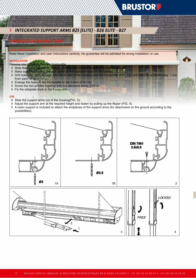
integrateD Support armS B25 (elite) - B26 elite - B27 ›
INSTALLATION INSTRUCTIONS
USER INSTRUCTIONSRead these installation and user instructions carefully . no guarantee will be admitted for wrong installation or use .
INSTALLATIONRemove one sideplate from the frontprofile .
Slide the housingprofile of the support arms into the slot at bottom of the frontprofile . ›make sure that there is enough space at the operation side for the handle . ›Drill holes dia . 3mm through the inferior slot of the housing and the frontprofile (FIG . 1a) . drill holes at approximately 1 .5m ›from each other .Enlarge the holes in the frontprofile to dia .3 .5mm .(FIG .1B) ›Screw the two profiles together with the delivered srews (FIG .2) ›Fix the sideplate back to the frontprofile . ›
USESlide the support arms out of the housing(FIG . 3) . ›adjust the support arm at the required height and fasten by pulling up the flipper (FIG . 4) . ›a nylon support is included to attach the endpieces of the support arms (for attachment on the ground according to the ›possibilities) .
DEALER SERVIC E MAN UAL © B RUSTOR LOU R DESSTRAAT 84 B-8940 GELUWE T. +32 (0) 56 .53 .18 .53 F. +32 (0) 56 .53 .18 .20 / 13
DEALER SERVICE MANUAL
==
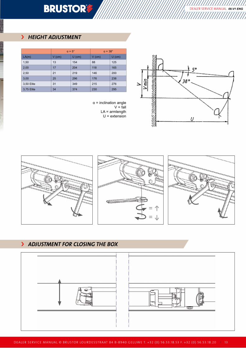
ɑ = 5° ɑ = 38°
la(m) V (cm) u (cm) V (cm) u (cm)
1,50 13 154 88 125
2,00 17 204 118 165
2,50 21 219 146 200
3,00 25 296 176 238
3,50 Elite 31 349 215 276
3,75 Elite 34 374 230 295
09.V1 ENG
HeigHt aDJuStment ›
ɑ = inclination angleV = fall
la = armlengthu = extension
aDJuStment for CloSing tHe BoX ›