Embed Size (px)
Citation preview
8182019 Munda Wear
httpslidepdfcomreaderfullmunda-wear 19
This article appeared in a journal published by Elsevier The attached
copy is furnished to the author for internal non-commercial research
and education use including for instruction at the authors institution
and sharing with colleagues
Other uses including reproduction and distribution or selling or
licensing copies or posting to personal institutional or third partywebsites are prohibited
In most cases authors are permitted to post their version of the
article (eg in Word or Tex form) to their personal website or
institutional repository Authors requiring further information
regarding Elsevierrsquos archiving and manuscript policies are
encouraged to visit
httpwwwelseviercomcopyright
8182019 Munda Wear
httpslidepdfcomreaderfullmunda-wear 29
Authors personal copy
Friction and wear properties of steel backed Alndash10Snndash4Sindash1Cu metallic strips
prepared via spray atomizationndashdeposition-rolling route
Parikshit Munda RK Dube Bikramjit Basu SC Koria
Department of Materials and Metallurgical Engineering Indian Institute of Technology Kanpur 208016 India
a b s t r a c ta r t i c l e i n f o
Article history
Received 16 February 2009
Accepted in revised form 12 May 2009
Available online 21 May 2009
Keywords
Steel backed bearing strip
AlndashSnndashSindashCu bearing strip
Fretting
Friction
Wear
Spray deposition
Rolling
In various load bearing structural applications related to automotive industries steel backed aluminum alloy
strips are considered For such applications it is desired to design appropriate alloy composition for metallic
stripso thatgood tribological properties canbe achievedIn ourongoingeffortsto accomplish thisaim we have
recently fabricated a steel backed Alndash10Snndash4Sindash1Cu bearing strip which is prepared by spray depositing the
molten bearing alloy on a steel substrate followed by warm rolling of theresulting laminatedstripto different
thickness reductions up to 80 The tribological performance of the steel backed Alndash10Snndash4Sindash1Cu strips is
evaluated against the bearing steel Whilethe recorded steady statecoef 1047297cient of friction (COF) does notshow
any noticeable difference (varying in the range of 06ndash07) with respect to difference in warm rolling
conditions the fretting wear rate (10ndash26times10minus5 mm3 Nminus1mminus1) of the steel backed and warm rolled strips
exhibits a systematic decrease in wear rate with increase in amount of warm rolling SEM-EDS analyses reveal
the oxidative wear and the extensive cracking of alumina rich tribolayer as the dominant material removal
mechanisms The tribological properties of the spray deposited and 80 rolled steel backed Alndash10Snndash4Sindash1Cu
bearing strip is compared with those of a commercially available AlndashSn based sleeve bearing under identical
fretting conditions
copy 2009 Elsevier BV All rights reserved
1 Introduction
Bimetallic strips are generally used for making bearings for the
crankshaft of an internal combustion engine Such a bimetallic strip
consists of a bearing layer which is metallurgically bonded to a
supporting steel strip Two approaches are widely adopted for pre-
paring such bimetallic strips The 1047297rst and the original approach is
based on powdermetallurgy It consists of spreadinga powder mass of
the chosen bearing alloy over a steel strip surface which is sub-
sequently heated to a suitable temperature in protective atmosphere
to bring about sintering between powder mass and supporting steelstrip The sintered ldquocompositerdquo strip is subsequently rolled and heat
treated to produce a dense layer of the bearing alloy metallurgically
bonded with the supporting steel strip The second approach consists
of preparing a thin strip of the chosen bearing alloy by casting or
powder metallurgy and subsequently the strip is roll bonded to form
the bimetallic strip
There has been a development in the above mentioned 1047297rst
approach for preparing bimetallic strip wherein liquid or semi-liquid
droplets of bearing alloys are deposited on the specially prepared
surface of the supporting steel strip Subsequently the laminated
composite ie the deposited bearing alloy together with the steel
strip is rolled and heat treated to form the bimetallic strip A most
convenient way of preparing liquid or semi-liquid droplets of the
bearing alloy is by gas atomization of liquid metals In principle the
manufacturing route consists of gas atomization of the chosen liquid
bearing alloy in a closed chamber and allowing the atomized droplets
to deposit on a steel strip substrate kept at a suitable distance below
the geometric point (also known as gas impingement point) of the
atomizer in the atomization chamber On cooling a laminatedcomposite strip is obtained in which the spray deposit of the bearing
layer is adhered with the supporting steel strip
Prior to atomization the surface of the steel strip substrate should be
shot blastedfor betteradherence of thespraydeposit withthe steel strip
surface In a batch type operation the thickness of the spray deposited
bearing layer could be controlled by the amount of the initial metal
taken for melting whereas in a continuous type it is controlled by the
speedof the traversing steelstrip substrateSubsequently the laminated
composite strip is rolled at a suitable temperature to obtain nearly full
density in the deposit good metallurgical bonding between bearing
alloylayer and steelstrip substrate and improved mechanicalproperties
The above manufacturing route for making bimetallic strip can be
designatedas ldquospray atomizationndashdeposition-rollingrdquo routeIt shouldbe
noted that a similar manufacturing route developed by Singer [1] has
Surface amp Coatings Technology 203 (2009) 3541ndash3548
Corresponding author Fax +91 512 2597505
E-mail address bikramiitkacin (B Basu)
0257-8972$ ndash see front matter copy 2009 Elsevier BV All rights reserved
doi101016jsurfcoat200905021
Contents lists available at ScienceDirect
Surface amp Coatings Technology
j o u r n a l h o m e p a g e w w w e l s ev i e r c o m l o c a t e s u r f c o a t
8182019 Munda Wear
httpslidepdfcomreaderfullmunda-wear 39
Authors personal copy
been investigated for preparing monolithic metal strip However not
enough research and development work has been carried out for
preparing steel backed bearing alloy strip by this route [2]
Aluminum alloys and copper alloys are two major materials used
for the bearing alloy layer The most common alloying element in
aluminum alloys is tin or lead which imparts the lubricating property
and compatibility However the environmental regulations restrictthe application of lead in bearing alloy layer In an earlier paper the
experimental results of the preparation of the steel backed AnndashSn
strip via spray atomizationndashdeposition-rolling route have been des-
cribed and discussed [3] The tribological behavior of such bimetallic
strip has also been reported therein [4]
Although AlndashSn alloys have good bearing qualities they are not
suitable forthe application in high speed and load engines Coppercan
be added to AlndashSn alloys to increase the strength of the aluminum
matrix It alsoenhancesthe fatigue property Copper is addedgenerally
in the range of 01ndash2 wt The wear resistance and the seizure resis-
tance of the bearing alloy layer can be improved by the addition of
silicon in the range of 3ndash4 wt [5] On the basis of all these con-
siderations a typical aluminum alloy composition for the bearing
application could be Almdash
10 wtSnmdash
4 wtSimdash
1 wt Cu (henceforthabbreviated as Alndash10Snndash4Sindash1Cu)
Friction and wear are of considerable importance in components
used for bearing applications It is important to understand the
tribological behavior of steel backed Alndash10Snndash4Sindash1Cu strip Fretting
as an important wear phenomenon refers to any situation in which
the contacts between materials are subjected to a low amplitude
oscillatory sliding motion [67] Fretting often takes place in hubs and
disks press 1047297tted to rotating shafts in riveted and bolted joints
between the strands of wire ropes and between the rolling elements
and their tracks in stationary ball and roller faces [6] The displace-
ment amplitude (5ndash300 microm) encountered in fretting are smaller than
those of reciprocating sliding [7] This means that contact is
maintained over most of the tribosurfaces during fretting As a result
much of the wear debris produced by fretting remains trapped at the
interface which can cause seizure in components such as 1047298exible
couplings [8] Another important aspect of fretting is the development
of fatigue cracks in the damaged region which reduces the fatigue
strength of the cyclically loaded components
In the present paper fretting wear behavior of the rolled and heat
treatedsteel backed Alndash10Snndash4Sindash1Cu viaspray atomizationndashdeposition-
rolling route against bearing steel has been investigated and discussed
An attemptis madeto identifythe dominantmechanisms responsiblefor
the wear during fretting The tribological behavior of the present bi-
metallic strip is also compared with that of the rolled and heat treated
steel backed Alndash10Sn alloy strips prepared via the same route [4] More
importantly a performance comparison is being made with commercial
AlndashSn bearing alloy used as sleeve bearings in a premier Indian
automotive company when tested under identical fretting conditions
2 Experimental
21 Materials
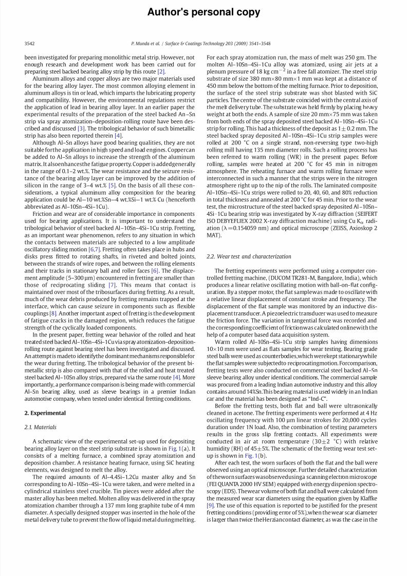
A schematic view of the experimental set-up used for depositing
bearing alloy layer on the steel strip substrate is shown in Fig 1(a) It
consists of a melting furnace a combined spray atomization and
deposition chamber A resistance heating furnace using SiC heating
elements was designed to melt the alloy
The required amounts of Alndash44Sindash12Cu master alloy and Sn
corresponding to Alndash10Snndash4Sindash1Cu were taken and were melted in a
cylindrical stainless steel crucible Tin pieces were added after the
master alloy has been melted Molten alloy was delivered in the spray
atomization chamber through a 137 mm long graphite tube of 4 mmdiameter A specially designed stopper was inserted in the hole of the
metal delivery tube to prevent the1047298ow of liquid metal duringmelting
For each spray atomization run the mass of melt was 250 gm The
molten Alndash10Snndash4Sindash1Cu alloy was atomized using air jets at a
plenum pressure of 18 kg cmminus2 in a free fall atomizer The steel strip
substrate of size 380 mmtimes80 mmtimes1 mm was kept at a distance of
450 mm below the bottom of the melting furnace Prior to deposition
the surface of the steel strip substrate was shot blasted with SiC
particles The centre of the substrate coincided with the central axis of the melt delivery tube The substrate was held 1047297rmly by placing heavy
weight at both the ends A sample of size 20 mmtimes75 mm was taken
from both ends of the spray deposited steel backed Alndash10Snndash4Sindash1Cu
strip for rolling This had a thickness of the deposit as 1plusmn 02 mm The
steel backed spray deposited Alndash10Snndash4Sindash1Cu strip samples were
rolled at 200 degC on a single strand non-reversing type two-high
rolling mill having 135 mm diameter rolls Such a rolling process has
been referred to warm rolling (WR) in the present paper Before
rolling samples were heated at 200 degC for 45 min in nitrogen
atmosphere The reheating furnace and warm rolling furnace were
interconnected in such a manner that the strips were in the nitrogen
atmosphere right up to the nip of the rolls The laminated composite
Alndash10Snndash4Sindash1Cu strips were rolled to 20 40 60 and 80 reduction
in total thickness and annealed at 200 degC for 45 min Prior to the weartest the microstructure of the steel backed spray deposited Alndash10Snndash
4Sindash1Cu bearing strip was investigated by X-ray diffraction (SEIFERT
ISO DEBYEFLIEX 2002 X-ray diffraction machine) using Cu Kα radi-
ation (λ=0154059 nm) and optical microscope (ZEISS Axioskop 2
MAT)
22 Wear test and characterization
The fretting experiments were performed using a computer con-
trolled fretting machine (DUCOM TR281-M Bangalore India) which
produces a linear relative oscillating motion with ball-on-1047298at con1047297g-
uration By a stepper motor the1047298at samplewas made to oscillate with
a relative linear displacement of constant stroke and frequency The
displacement of the 1047298at sample was monitored by an inductive dis-
placement transducer A piezoelectric transducer was used to measure
the friction force The variation in tangential force was recorded and
the corresponding coef 1047297cient of frictionwas calculated onlinewith the
help of a computer based data acquisition system
Warm rolled Alndash10Snndash4Sindash1Cu strip samples having dimensions
10times10 mm were used as 1047298ats samples for wear testing Bearing grade
steel balls were used as counterbodieswhich werekept stationarywhile
the1047298at samples were subjectedto reciprocatingmotion Forcomparison
fretting tests were also conducted on commercial steel backed AlndashSn
sleeve bearing alloy under identical conditions The commercial sample
was procured from a leading Indian automotive industry and this alloy
contains around 14SnThis bearing material is used widely in an Indian
car and the material has been designed as ldquoInd-Crdquo
Before the fretting tests both 1047298at and ball were ultrasonicallycleaned in acetone The fretting experiments were performed at 4 Hz
oscillating frequency with 100 microm linear strokes for 20000 cycles
duration under 1N load Also the combination of testing parameters
results in the gross slip fretting contacts All experiments were
conducted in air at room temperature (30plusmn2 degC) with relative
humidity (RH) of 45plusmn5 The schematic of the fretting wear test set-
up is shown in Fig 1(b)
After each test the worn surfaces of both the 1047298at and the ball were
observed using an optical microscope Further detailed characterization
of theworn surfaces wasobservedusinga scanning electron microscope
(FEI QUANTA 2000 HV SEM) equipped with energy dispersion spectro-
scopy (EDS) Thewear volume of both 1047298at and ball were calculated from
the measured wear scar diameters using the equation given by Klaffke
[9] The use of this equation is reported to be justi1047297ed for the presentfretting conditions (providing error of 5)when the wear scar diameter
is larger than twice theHerziancontact diameter as was the case in the
3542 P Munda et al Surface amp Coatings Technology 203 (2009) 3541ndash 3548
8182019 Munda Wear
httpslidepdfcomreaderfullmunda-wear 49
Authors personal copy
present experiments From the estimated wear volume the speci1047297c
wear rates [(wear volume)(loadtimesdistance)] are calculated
3 Results and discussion
31 Porosity and phases present in the spray deposited and warm rolled
steel backed Alndash10Snndash4Sindash1Cu strip
The porosity in the bearing layer of the steel backed Alndash10Snndash4Sindash
1Cu strip after different amount of thickness reduction by warm
rolling is given in Table 1 It can be seen that the porosity in the bearing
layer is decreased with increased percentage of warm rolling The
porosity after 80 warm rolling is ~05 A representative optical
microscopy image of 80 rolled is provided in Fig 2(a)
In order to illustrate thephase assemblageof the thin bearing strip a
representative XRDplot of the80 rolledsampleis provided in Fig 2(b)
While thestrongpeaksof Al matrixand Sn precipitatesare recordedthe
minor peaks from thesecondphases eg Siand Al2O3 are also observedThe formation of any reaction phases is not observed within the
detectable limit of the XRD unit under the present condition
Fig 1 Schematic diagram of spray atomization and deposition set-up (a) and fretting wear test set-up (b)
3543P Munda et al Surface amp Coatings Technology 203 (2009) 3541ndash 3548
8182019 Munda Wear
httpslidepdfcomreaderfullmunda-wear 59
Authors personal copy
32 Friction and wear properties
In order to assess the in1047298uence of the processing conditions on
the frictional properties the fretting wear tests were carried out on
Alndash10Snndash4Sindash1Cu strip warm rolled with variation in the thickness
reduction of 20ndash80 The continuously recorded coef 1047297cient of friction
is plotted in Fig 3 Duringthe initial 1000 cycles theCOF rises to a very
high value of 07ndash09 and thereafter it attains a steady state value The
steady state COF varies in the narrow window of 06ndash07 independent
of warm rolling thickness reduction Therefore it can be said that thewarm rolling conditions as used in the present work do not have any
signi1047297cant in1047298uence on frictional properties of steel backed Alndash10Snndash
4Sindash1Cu strip against bearing steel ball It can be pointed out here that
all the investigated strips after different amount of warm rolling
contain porosity in the range of 05ndash105
In an earlier work the steady state COF of steel backed Alndash10Sn
bearing strip after similar level of warm rolling exhibited steady state
COF between 075 and 12 against steel counterbody under identicalfretting conditionThose bearing strips however had different level of
porosity and were in the range of 9ndash31 [4]
The speci1047297c wear rate of the spray deposited and warm rolled steel
backed Alndash10Snndash4Sindash1Cu strips were calculated from measured wear
scar diameter of the worn surfaces of the respective samples after
fretting under investigated conditions The wear rate decreases in a
systematic linear manner with percent warm rolling which can be
seen in Fig 4(a) At the highest warm rolling conditions (80) the
wear loss of Alndash10Snndash4Sindash1Cu is the lowest In an effort to analyze the
in1047298uence of the porosity on wear resistance Fig 4(b) plots the wear
rate versus percent porosity It is clear that wear rate increases with
porosity and the strip with 05 porosity exhibited highest wear
resistance
33 Worn surface topography of the spray deposited warm rolled steel
backed Alndash10Snndash4Sindash1Cu strip
Detailed microstructural investigation using SEM-EDS was carried
out on the worn surfaces of warm rolled steel backed Alndash10Snndash4Sindash
1Cu spray deposit to understand the mechanism governing the
fretting wear Fig 5(a) displays the overall topographical features of
the worn scar formed on the surface of the 20 warm rolled Alndash10Snndash
4Sindash1Cu spray deposit strip after 20000 cycles under 1N load for
100 microm linear amplitude and 4 Hz frequency against bearing grade
steel ball It is clear from Fig 5(a) that the entire surface is covered
with the tribochemical layer with different topographical contrast
The details of such layer can be seenwithmore clarity in Fig 5(b) The
extensive cracking canbe seen both along thefrettingdirection as well
as perpendicular to the fretting direction Also the cracking has been
found to be more severe near the central region of the worn surface
No evidence of abrasion or plastic 1047298owcan be seen EDS compositional
analysis of multiple areas of the worn surface reveals that the
tribochemical layer is essentially alumina rich Also the intensityof the
Fe-peak appears to be very weak essentially indicating insigni1047297cant
Table 1
Percent porosity and speci1047297c wear rate of spray deposited Alndash10Snndash4Sindash1Cu strip as a
function of percent warm rolling (WR)
S no Sample Porosity COF Speci1047297c wear rate
(times10minus5 mm3 Nminus1 mminus1)
1 Alndash10Snndash4Sindash1Cu20WR 105 066 26
2 Alndash10Snndash4Sindash1Cu40WR 37 068 22
3 Alndash10Snndash4Sindash1Cu60WR 12 061 16
4 Alndash10Snndash4Sindash1Cu80WR 05 063 10
5 Ind-C (Alndash14Sn)as received ndash 075 18
Fig 2 Optical micrograph of steel backed and 80 warm rolled Alndash10Snndash4Sindash1Cu strip
(a) and XRD plot of steel backed and 80 warm rolled Alndash10Snndash4Sindash1Cu strip
Fig 3 Coef 1047297cient of friction of spray deposited(SD) steel backed80 thicknessreduction
and commercial sleeve bearing Ind-C as a function of number of cycles
3544 P Munda et al Surface amp Coatings Technology 203 (2009) 3541ndash 3548
8182019 Munda Wear
httpslidepdfcomreaderfullmunda-wear 69
Authors personal copy
transfer of materials from mating counterbody (steel ball) One
representative EDS spectrum is provided in the inset of Fig 5(b)
When the same metallic strip after 40 warm rolling is fretted
under identical conditions we observed much extensive cracking of
the tribochemical layer throughout the worn surface Also a largeamount of wear debris particles (both 1047297ner in size as well as
agglomerated) are found around the periphery of the worn surface
The details of the wear debris particles in terms of size and shape can
be seenin the inset of Fig 6(a) Largely thewear debrisparticles areof
submicron size with few agglomerated irregular shaped debris
particles appearing in sizes of less than 10 microm Again EDS composi-
tional analysiscon1047297rms[inset of Fig6(b)] thepresence of alumina rich
tribochemical layer The fragmentation of the tribochemical layers can
be clearly seen in Fig 6(b) It is easy to realize that during continuous
fretting process a number of fragmented parts of tribochemical layer
with sizes in the range of 50ndash100 micromcan beeasilyspalled and thiswill
lead to the subsequent wear of the underlying material
In case of the same Alndash10Snndash4Sindash1Cu based metallic strip after 60
warm rolling similar topographical features are clearly observed [seeFig 7(a)] Thedetailed topographical observations as shown in Fig 7(b)
reveal the extensive occurrence of cracking A comparison of Fig 7(b)
with Fig 6(b) however con1047297rms that the severity of fretting induced
damage is noticeably reduced as the percent warm rolling increased
from 40 to 60
Fig 8(a) and (b) show typical SEM images showing overall
topography of worm surfaces of the metallic strip with the highest
percent warm rolling (80) The worn surface exhibits even much less
cracking induced damage mechanism [see brighter contrast area inFig 8(a)] The major part of the worn surface is however covered with
tribolayer Also signi1047297cant amount of 1047297ner and agglomerated debris
particles are observed in the regions adjacent to the edges of wear
scar Like in other cases the amount of Fe transfer to worn surface is
minimum
From the above observations it should be clear that oxidative
wear and cracking of the tribochemical layer are the major wear
Fig 4 Speci1047297c wear rate of Alndash10Snndash4Sindash1Cu as function of percent warm rolling (a)
and percent porosity (b)
Fig 5 Typical SEM images at different magni1047297
cations showing overall topography of worn surfaces of spray deposited and 20 warm rolled Alndash10Snndash4Sindash1Cu strip fretting
conditions-20000 cycles 4 Hz frequency100 microm stroke length counter body bearing
steel arrows indicate fretting direction
3545P Munda et al Surface amp Coatings Technology 203 (2009) 3541ndash 3548
8182019 Munda Wear
httpslidepdfcomreaderfullmunda-wear 79
Authors personal copy
mechanisms Duringthe initial stageAl is oxidizedto form Al2O3 layer
During repeated fretting stroke Al2O3 rich tribolayer cracks and a
number of cracked islands of wear fragments are formed The obser-
vation of large amount of wear debris particles around the wear scar
periphery indicates that such debris particles are formed due to re-
peated fracturing of suchwear fragmentsand subsequently ejected out
from the tribological interface
34 Comparison of the tribological behavior of the present material with
that of other materials
The tribological behavior of the spray deposited and warm rolled
steel backed Alndash10Snndash4Sindash1Cu strip was compared with that of sleeve
bearing material (designated as Ind-C) used widely in an Indian car
The EDS analysis of the bearing layer showed that it was basically
aluminum-based having approximately 14ndash15 wt tin as the major
alloying element Fig 3 also plots the continuously recorded
coef 1047297cient of friction of the Ind-C material During the initial
1000 cycles the COF rises to a high value of 08 and thereafter it
attains a steady state value The steady state COF varies in the narrow
range of 07ndash08 having an average value of 075 The speci1047297c wear
rate of the Ind-C material was found to be 18times10minus5 mm3 Nminus1mminus1 It
can be seen that the COF value and the speci1047297c wear rate of the Ind-C
material is greater than that of the spray deposited and 80 warm
rolled steel backed Alndash10Snndash4Sindash1Cu strip (containing 05 porosity)
used in the present study Thecorrespondingvalueof average COFand
speci1047297c wear ratewere 063 and 10times 10minus5 mm3 Nminus1mminus1 respectively
(Table 1)Fig9(a) shows representative SEM image of the overall topography
of the worn surface formed on the Ind-C material after 20000 cycles
Fig 6 Typical SEM images at different magni1047297
cations showing overall topography of worn surfaces of spray deposited and 40 warm rolled Alndash10Snndash4Sindash1Cu strip fretting
conditions-20000 cycles 4 Hz frequency100 microm stroke length counter body bearing
steel arrows indicate fretting direction
Fig 7 Typical SEM images at different magni1047297cations showing overall topography of
worn surfaces of spray deposited and 60 warm rolled Alndash10Snndash4Sindash1Cu strip fretting
conditions-20000 cycles 4 Hz frequency100 microm stroke length counter body bearing
steel arrows indicate fretting direction
3546 P Munda et al Surface amp Coatings Technology 203 (2009) 3541ndash 3548
8182019 Munda Wear
httpslidepdfcomreaderfullmunda-wear 89
Authors personal copy
under 1N load for 100 microm linearamplitude and 4 Hz frequency against
bearing grade steel ball It is clear that thecommercial bearing material
experiences extensive tribochemical wear More signi1047297cantly large
amount of coarsesheet like wear debrisparticles arefound to disperse
around wear scar edge Also 1047297ner wear debris particles are also
observed The details of the tribological layer formed on the surface can
be seen more clearly in Fig 9(b) Extensive cracking of the
tribochemical layer along with severe fragmentation of tribochemical
layer are evident EDS analysis con1047297rms that tribochemical layer is
essentially oxide rich The amount of steel transfer to 1047298at is negligible
The implication of the present work is important In our earlier
work we reported the tribological properties of Alndash10Sn metallic strip
under identical fretting conditions One of the important results was
that Alndash10Sn alloy when warm rolled 75thickness reductionexhibits high COF of 09This material was prepared using the same
approach as used for steel backed Alndash10Snndash4Sindash1Cu bearing strip [4]
The present work demonstrates that suitable alloy design ap-
proach can enable us to develop better metallic strip of Alndash10Snndash4Sindash
1Cu composition having a lower of COF of 063 From the aspect of real
applications any tribological material experiencing lower friction is
always preferred This is due to the fact that the dissipated energy will
be lower in case of material combinations with lower COF and as a
result lower energy needs to be supplied from external source tomaintain relative motion at the tribological interface On the basis of
the present study it should be clear that the WR-80 sample should be
preferred over commercial sleeve bearing alloy (Ind-C sample) for
given automotive applications This will ensure longer durability cou-
pled with energy savings as well as from economic aspect (less fre-
quent replacement)
Theadvantage forthe useof Alndash10Snndash4Sindash1Cualloyoverthe Alndash10Sn
alloy produced via the same processing route can also be mentioned
Fig 8 Typical SEM images at different magni1047297cations showing overall topography of
worn surfaces of spray deposited and 20 warm rolled Alndash10Snndash4Sindash1Cu strip fretting
conditionsmdash20000 cycles 4 Hz frequency100 microm stroke length counter body bearing
steel arrows indicate fretting direction
Fig 9 Typical SEM images at different magni1047297
cations showing overall topography of worn surfaces of AlndashSn commercial sleeve bearing (Ind-C) fretting conditionsmdash
20000 cycles 4 Hz frequency 100 microm stroke length counter body bearing steel
arrows indicate fretting direction
3547P Munda et al Surface amp Coatings Technology 203 (2009) 3541ndash 3548
8182019 Munda Wear
httpslidepdfcomreaderfullmunda-wear 99
Authors personal copy
fromthe processingaspect Fromthe manufacturing aspect the addition
of Si enhances the 1047298uidity of the melt and thereby ensures a moredense
spray deposit of the bearing layer on the steel substrate As a result steel
backed Alndash10Snndash4Sindash1Cu bearing alloy strip will require less amount of
warm rolling for achieving near full density in the bearing layer as
compared to steel backed Alndash10Sn bearing alloy strip produced under
identical condition of spray deposition and rolling
4 Conclusions
In the present work the steel backed and warm rolled Alndash10Snndash
4Sindash1Cu metallic strips were fretted against bearing steel Based on
our experimental observations the following conclusions are drawn
a No signi1047297cant difference in terms of the frictional behavior was
observed when the metallic strips warm rolled to varying thick-
ness reductions of up to 80 were subjected to fretting wear
against steel Independent of warm rolling conditions the steady
state COF varies in the narrow window of 06ndash07
b The speci1047297c wear rate decreases in a systematic linear manner
with percentage warm rolling of spray atomized layer The wear
rate of 80 warm rolled steel backed Alndash10Snndash4Sindash1Cu strip wasfound to be 10times10minus5 mm3Nminus1mminus1
c The tribooxidation is the dominant wear mechanism and the
formation of alumina rich tribolayer is observed irrespective of
warm rolling conditions The cracking of tribolayer and signi1047297cant
wear debris (both submicron and agglomerated) formation are
found to be additional mechanisms
d The COF of the spray deposited and 80 warm rolled steel backed
Alndash10Snndash4Sindash1Cu stripshas beenfound to belowerthan thatof the
spray deposited Alndash10Sn composition subjected to similar amount
of warm rolling
e The COF value and the speci1047297c wear rate of the present materialwarmrolled to80 has beenfoundto belowerthan thatof a typical
steel backed AlndashSn bearing alloy strip used in a commercially pro-
duced Indian passenger car
References
[1] ARE Singer Met Mater 4 (1970) 246[2] MR Tripathy Properties of steel backed AlndashSn strip prepared via spray atomizationndash
deposition-rolling route MTech dissertation Indian Institute of Technology KanpurIndia 2005
[3] MR Tripathy RK Dube SC Koria J Mater Process Technol 190 (2007) 342[4] MR Tripathy BV Manoj Kumar B Basu RK Dube SC Koria Mater Sci Technol
23 (2007) 15[5] T Desaki S Kamiya K Sato Y Okauchi and T Nukami Aluminum alloy for sliding
bearing and its production method US Patent no6 706126 B2 Mar 16 2004[6] IM Hutchings Tribology Friction and Wearof Engineering Materials Edward Arnold
London 1992[7] O Vingsbo S Stierberg Wear 126 (1988) 131[8] AD Sarkar Friction and Wear Academic Press London 1980[9] D Klaffke Tribol Int 22 (2) (1989) 89
3548 P Munda et al Surface amp Coatings Technology 203 (2009) 3541ndash 3548
8182019 Munda Wear
httpslidepdfcomreaderfullmunda-wear 29
Authors personal copy
Friction and wear properties of steel backed Alndash10Snndash4Sindash1Cu metallic strips
prepared via spray atomizationndashdeposition-rolling route
Parikshit Munda RK Dube Bikramjit Basu SC Koria
Department of Materials and Metallurgical Engineering Indian Institute of Technology Kanpur 208016 India
a b s t r a c ta r t i c l e i n f o
Article history
Received 16 February 2009
Accepted in revised form 12 May 2009
Available online 21 May 2009
Keywords
Steel backed bearing strip
AlndashSnndashSindashCu bearing strip
Fretting
Friction
Wear
Spray deposition
Rolling
In various load bearing structural applications related to automotive industries steel backed aluminum alloy
strips are considered For such applications it is desired to design appropriate alloy composition for metallic
stripso thatgood tribological properties canbe achievedIn ourongoingeffortsto accomplish thisaim we have
recently fabricated a steel backed Alndash10Snndash4Sindash1Cu bearing strip which is prepared by spray depositing the
molten bearing alloy on a steel substrate followed by warm rolling of theresulting laminatedstripto different
thickness reductions up to 80 The tribological performance of the steel backed Alndash10Snndash4Sindash1Cu strips is
evaluated against the bearing steel Whilethe recorded steady statecoef 1047297cient of friction (COF) does notshow
any noticeable difference (varying in the range of 06ndash07) with respect to difference in warm rolling
conditions the fretting wear rate (10ndash26times10minus5 mm3 Nminus1mminus1) of the steel backed and warm rolled strips
exhibits a systematic decrease in wear rate with increase in amount of warm rolling SEM-EDS analyses reveal
the oxidative wear and the extensive cracking of alumina rich tribolayer as the dominant material removal
mechanisms The tribological properties of the spray deposited and 80 rolled steel backed Alndash10Snndash4Sindash1Cu
bearing strip is compared with those of a commercially available AlndashSn based sleeve bearing under identical
fretting conditions
copy 2009 Elsevier BV All rights reserved
1 Introduction
Bimetallic strips are generally used for making bearings for the
crankshaft of an internal combustion engine Such a bimetallic strip
consists of a bearing layer which is metallurgically bonded to a
supporting steel strip Two approaches are widely adopted for pre-
paring such bimetallic strips The 1047297rst and the original approach is
based on powdermetallurgy It consists of spreadinga powder mass of
the chosen bearing alloy over a steel strip surface which is sub-
sequently heated to a suitable temperature in protective atmosphere
to bring about sintering between powder mass and supporting steelstrip The sintered ldquocompositerdquo strip is subsequently rolled and heat
treated to produce a dense layer of the bearing alloy metallurgically
bonded with the supporting steel strip The second approach consists
of preparing a thin strip of the chosen bearing alloy by casting or
powder metallurgy and subsequently the strip is roll bonded to form
the bimetallic strip
There has been a development in the above mentioned 1047297rst
approach for preparing bimetallic strip wherein liquid or semi-liquid
droplets of bearing alloys are deposited on the specially prepared
surface of the supporting steel strip Subsequently the laminated
composite ie the deposited bearing alloy together with the steel
strip is rolled and heat treated to form the bimetallic strip A most
convenient way of preparing liquid or semi-liquid droplets of the
bearing alloy is by gas atomization of liquid metals In principle the
manufacturing route consists of gas atomization of the chosen liquid
bearing alloy in a closed chamber and allowing the atomized droplets
to deposit on a steel strip substrate kept at a suitable distance below
the geometric point (also known as gas impingement point) of the
atomizer in the atomization chamber On cooling a laminatedcomposite strip is obtained in which the spray deposit of the bearing
layer is adhered with the supporting steel strip
Prior to atomization the surface of the steel strip substrate should be
shot blastedfor betteradherence of thespraydeposit withthe steel strip
surface In a batch type operation the thickness of the spray deposited
bearing layer could be controlled by the amount of the initial metal
taken for melting whereas in a continuous type it is controlled by the
speedof the traversing steelstrip substrateSubsequently the laminated
composite strip is rolled at a suitable temperature to obtain nearly full
density in the deposit good metallurgical bonding between bearing
alloylayer and steelstrip substrate and improved mechanicalproperties
The above manufacturing route for making bimetallic strip can be
designatedas ldquospray atomizationndashdeposition-rollingrdquo routeIt shouldbe
noted that a similar manufacturing route developed by Singer [1] has
Surface amp Coatings Technology 203 (2009) 3541ndash3548
Corresponding author Fax +91 512 2597505
E-mail address bikramiitkacin (B Basu)
0257-8972$ ndash see front matter copy 2009 Elsevier BV All rights reserved
doi101016jsurfcoat200905021
Contents lists available at ScienceDirect
Surface amp Coatings Technology
j o u r n a l h o m e p a g e w w w e l s ev i e r c o m l o c a t e s u r f c o a t
8182019 Munda Wear
httpslidepdfcomreaderfullmunda-wear 39
Authors personal copy
been investigated for preparing monolithic metal strip However not
enough research and development work has been carried out for
preparing steel backed bearing alloy strip by this route [2]
Aluminum alloys and copper alloys are two major materials used
for the bearing alloy layer The most common alloying element in
aluminum alloys is tin or lead which imparts the lubricating property
and compatibility However the environmental regulations restrictthe application of lead in bearing alloy layer In an earlier paper the
experimental results of the preparation of the steel backed AnndashSn
strip via spray atomizationndashdeposition-rolling route have been des-
cribed and discussed [3] The tribological behavior of such bimetallic
strip has also been reported therein [4]
Although AlndashSn alloys have good bearing qualities they are not
suitable forthe application in high speed and load engines Coppercan
be added to AlndashSn alloys to increase the strength of the aluminum
matrix It alsoenhancesthe fatigue property Copper is addedgenerally
in the range of 01ndash2 wt The wear resistance and the seizure resis-
tance of the bearing alloy layer can be improved by the addition of
silicon in the range of 3ndash4 wt [5] On the basis of all these con-
siderations a typical aluminum alloy composition for the bearing
application could be Almdash
10 wtSnmdash
4 wtSimdash
1 wt Cu (henceforthabbreviated as Alndash10Snndash4Sindash1Cu)
Friction and wear are of considerable importance in components
used for bearing applications It is important to understand the
tribological behavior of steel backed Alndash10Snndash4Sindash1Cu strip Fretting
as an important wear phenomenon refers to any situation in which
the contacts between materials are subjected to a low amplitude
oscillatory sliding motion [67] Fretting often takes place in hubs and
disks press 1047297tted to rotating shafts in riveted and bolted joints
between the strands of wire ropes and between the rolling elements
and their tracks in stationary ball and roller faces [6] The displace-
ment amplitude (5ndash300 microm) encountered in fretting are smaller than
those of reciprocating sliding [7] This means that contact is
maintained over most of the tribosurfaces during fretting As a result
much of the wear debris produced by fretting remains trapped at the
interface which can cause seizure in components such as 1047298exible
couplings [8] Another important aspect of fretting is the development
of fatigue cracks in the damaged region which reduces the fatigue
strength of the cyclically loaded components
In the present paper fretting wear behavior of the rolled and heat
treatedsteel backed Alndash10Snndash4Sindash1Cu viaspray atomizationndashdeposition-
rolling route against bearing steel has been investigated and discussed
An attemptis madeto identifythe dominantmechanisms responsiblefor
the wear during fretting The tribological behavior of the present bi-
metallic strip is also compared with that of the rolled and heat treated
steel backed Alndash10Sn alloy strips prepared via the same route [4] More
importantly a performance comparison is being made with commercial
AlndashSn bearing alloy used as sleeve bearings in a premier Indian
automotive company when tested under identical fretting conditions
2 Experimental
21 Materials
A schematic view of the experimental set-up used for depositing
bearing alloy layer on the steel strip substrate is shown in Fig 1(a) It
consists of a melting furnace a combined spray atomization and
deposition chamber A resistance heating furnace using SiC heating
elements was designed to melt the alloy
The required amounts of Alndash44Sindash12Cu master alloy and Sn
corresponding to Alndash10Snndash4Sindash1Cu were taken and were melted in a
cylindrical stainless steel crucible Tin pieces were added after the
master alloy has been melted Molten alloy was delivered in the spray
atomization chamber through a 137 mm long graphite tube of 4 mmdiameter A specially designed stopper was inserted in the hole of the
metal delivery tube to prevent the1047298ow of liquid metal duringmelting
For each spray atomization run the mass of melt was 250 gm The
molten Alndash10Snndash4Sindash1Cu alloy was atomized using air jets at a
plenum pressure of 18 kg cmminus2 in a free fall atomizer The steel strip
substrate of size 380 mmtimes80 mmtimes1 mm was kept at a distance of
450 mm below the bottom of the melting furnace Prior to deposition
the surface of the steel strip substrate was shot blasted with SiC
particles The centre of the substrate coincided with the central axis of the melt delivery tube The substrate was held 1047297rmly by placing heavy
weight at both the ends A sample of size 20 mmtimes75 mm was taken
from both ends of the spray deposited steel backed Alndash10Snndash4Sindash1Cu
strip for rolling This had a thickness of the deposit as 1plusmn 02 mm The
steel backed spray deposited Alndash10Snndash4Sindash1Cu strip samples were
rolled at 200 degC on a single strand non-reversing type two-high
rolling mill having 135 mm diameter rolls Such a rolling process has
been referred to warm rolling (WR) in the present paper Before
rolling samples were heated at 200 degC for 45 min in nitrogen
atmosphere The reheating furnace and warm rolling furnace were
interconnected in such a manner that the strips were in the nitrogen
atmosphere right up to the nip of the rolls The laminated composite
Alndash10Snndash4Sindash1Cu strips were rolled to 20 40 60 and 80 reduction
in total thickness and annealed at 200 degC for 45 min Prior to the weartest the microstructure of the steel backed spray deposited Alndash10Snndash
4Sindash1Cu bearing strip was investigated by X-ray diffraction (SEIFERT
ISO DEBYEFLIEX 2002 X-ray diffraction machine) using Cu Kα radi-
ation (λ=0154059 nm) and optical microscope (ZEISS Axioskop 2
MAT)
22 Wear test and characterization
The fretting experiments were performed using a computer con-
trolled fretting machine (DUCOM TR281-M Bangalore India) which
produces a linear relative oscillating motion with ball-on-1047298at con1047297g-
uration By a stepper motor the1047298at samplewas made to oscillate with
a relative linear displacement of constant stroke and frequency The
displacement of the 1047298at sample was monitored by an inductive dis-
placement transducer A piezoelectric transducer was used to measure
the friction force The variation in tangential force was recorded and
the corresponding coef 1047297cient of frictionwas calculated onlinewith the
help of a computer based data acquisition system
Warm rolled Alndash10Snndash4Sindash1Cu strip samples having dimensions
10times10 mm were used as 1047298ats samples for wear testing Bearing grade
steel balls were used as counterbodieswhich werekept stationarywhile
the1047298at samples were subjectedto reciprocatingmotion Forcomparison
fretting tests were also conducted on commercial steel backed AlndashSn
sleeve bearing alloy under identical conditions The commercial sample
was procured from a leading Indian automotive industry and this alloy
contains around 14SnThis bearing material is used widely in an Indian
car and the material has been designed as ldquoInd-Crdquo
Before the fretting tests both 1047298at and ball were ultrasonicallycleaned in acetone The fretting experiments were performed at 4 Hz
oscillating frequency with 100 microm linear strokes for 20000 cycles
duration under 1N load Also the combination of testing parameters
results in the gross slip fretting contacts All experiments were
conducted in air at room temperature (30plusmn2 degC) with relative
humidity (RH) of 45plusmn5 The schematic of the fretting wear test set-
up is shown in Fig 1(b)
After each test the worn surfaces of both the 1047298at and the ball were
observed using an optical microscope Further detailed characterization
of theworn surfaces wasobservedusinga scanning electron microscope
(FEI QUANTA 2000 HV SEM) equipped with energy dispersion spectro-
scopy (EDS) Thewear volume of both 1047298at and ball were calculated from
the measured wear scar diameters using the equation given by Klaffke
[9] The use of this equation is reported to be justi1047297ed for the presentfretting conditions (providing error of 5)when the wear scar diameter
is larger than twice theHerziancontact diameter as was the case in the
3542 P Munda et al Surface amp Coatings Technology 203 (2009) 3541ndash 3548
8182019 Munda Wear
httpslidepdfcomreaderfullmunda-wear 49
Authors personal copy
present experiments From the estimated wear volume the speci1047297c
wear rates [(wear volume)(loadtimesdistance)] are calculated
3 Results and discussion
31 Porosity and phases present in the spray deposited and warm rolled
steel backed Alndash10Snndash4Sindash1Cu strip
The porosity in the bearing layer of the steel backed Alndash10Snndash4Sindash
1Cu strip after different amount of thickness reduction by warm
rolling is given in Table 1 It can be seen that the porosity in the bearing
layer is decreased with increased percentage of warm rolling The
porosity after 80 warm rolling is ~05 A representative optical
microscopy image of 80 rolled is provided in Fig 2(a)
In order to illustrate thephase assemblageof the thin bearing strip a
representative XRDplot of the80 rolledsampleis provided in Fig 2(b)
While thestrongpeaksof Al matrixand Sn precipitatesare recordedthe
minor peaks from thesecondphases eg Siand Al2O3 are also observedThe formation of any reaction phases is not observed within the
detectable limit of the XRD unit under the present condition
Fig 1 Schematic diagram of spray atomization and deposition set-up (a) and fretting wear test set-up (b)
3543P Munda et al Surface amp Coatings Technology 203 (2009) 3541ndash 3548
8182019 Munda Wear
httpslidepdfcomreaderfullmunda-wear 59
Authors personal copy
32 Friction and wear properties
In order to assess the in1047298uence of the processing conditions on
the frictional properties the fretting wear tests were carried out on
Alndash10Snndash4Sindash1Cu strip warm rolled with variation in the thickness
reduction of 20ndash80 The continuously recorded coef 1047297cient of friction
is plotted in Fig 3 Duringthe initial 1000 cycles theCOF rises to a very
high value of 07ndash09 and thereafter it attains a steady state value The
steady state COF varies in the narrow window of 06ndash07 independent
of warm rolling thickness reduction Therefore it can be said that thewarm rolling conditions as used in the present work do not have any
signi1047297cant in1047298uence on frictional properties of steel backed Alndash10Snndash
4Sindash1Cu strip against bearing steel ball It can be pointed out here that
all the investigated strips after different amount of warm rolling
contain porosity in the range of 05ndash105
In an earlier work the steady state COF of steel backed Alndash10Sn
bearing strip after similar level of warm rolling exhibited steady state
COF between 075 and 12 against steel counterbody under identicalfretting conditionThose bearing strips however had different level of
porosity and were in the range of 9ndash31 [4]
The speci1047297c wear rate of the spray deposited and warm rolled steel
backed Alndash10Snndash4Sindash1Cu strips were calculated from measured wear
scar diameter of the worn surfaces of the respective samples after
fretting under investigated conditions The wear rate decreases in a
systematic linear manner with percent warm rolling which can be
seen in Fig 4(a) At the highest warm rolling conditions (80) the
wear loss of Alndash10Snndash4Sindash1Cu is the lowest In an effort to analyze the
in1047298uence of the porosity on wear resistance Fig 4(b) plots the wear
rate versus percent porosity It is clear that wear rate increases with
porosity and the strip with 05 porosity exhibited highest wear
resistance
33 Worn surface topography of the spray deposited warm rolled steel
backed Alndash10Snndash4Sindash1Cu strip
Detailed microstructural investigation using SEM-EDS was carried
out on the worn surfaces of warm rolled steel backed Alndash10Snndash4Sindash
1Cu spray deposit to understand the mechanism governing the
fretting wear Fig 5(a) displays the overall topographical features of
the worn scar formed on the surface of the 20 warm rolled Alndash10Snndash
4Sindash1Cu spray deposit strip after 20000 cycles under 1N load for
100 microm linear amplitude and 4 Hz frequency against bearing grade
steel ball It is clear from Fig 5(a) that the entire surface is covered
with the tribochemical layer with different topographical contrast
The details of such layer can be seenwithmore clarity in Fig 5(b) The
extensive cracking canbe seen both along thefrettingdirection as well
as perpendicular to the fretting direction Also the cracking has been
found to be more severe near the central region of the worn surface
No evidence of abrasion or plastic 1047298owcan be seen EDS compositional
analysis of multiple areas of the worn surface reveals that the
tribochemical layer is essentially alumina rich Also the intensityof the
Fe-peak appears to be very weak essentially indicating insigni1047297cant
Table 1
Percent porosity and speci1047297c wear rate of spray deposited Alndash10Snndash4Sindash1Cu strip as a
function of percent warm rolling (WR)
S no Sample Porosity COF Speci1047297c wear rate
(times10minus5 mm3 Nminus1 mminus1)
1 Alndash10Snndash4Sindash1Cu20WR 105 066 26
2 Alndash10Snndash4Sindash1Cu40WR 37 068 22
3 Alndash10Snndash4Sindash1Cu60WR 12 061 16
4 Alndash10Snndash4Sindash1Cu80WR 05 063 10
5 Ind-C (Alndash14Sn)as received ndash 075 18
Fig 2 Optical micrograph of steel backed and 80 warm rolled Alndash10Snndash4Sindash1Cu strip
(a) and XRD plot of steel backed and 80 warm rolled Alndash10Snndash4Sindash1Cu strip
Fig 3 Coef 1047297cient of friction of spray deposited(SD) steel backed80 thicknessreduction
and commercial sleeve bearing Ind-C as a function of number of cycles
3544 P Munda et al Surface amp Coatings Technology 203 (2009) 3541ndash 3548
8182019 Munda Wear
httpslidepdfcomreaderfullmunda-wear 69
Authors personal copy
transfer of materials from mating counterbody (steel ball) One
representative EDS spectrum is provided in the inset of Fig 5(b)
When the same metallic strip after 40 warm rolling is fretted
under identical conditions we observed much extensive cracking of
the tribochemical layer throughout the worn surface Also a largeamount of wear debris particles (both 1047297ner in size as well as
agglomerated) are found around the periphery of the worn surface
The details of the wear debris particles in terms of size and shape can
be seenin the inset of Fig 6(a) Largely thewear debrisparticles areof
submicron size with few agglomerated irregular shaped debris
particles appearing in sizes of less than 10 microm Again EDS composi-
tional analysiscon1047297rms[inset of Fig6(b)] thepresence of alumina rich
tribochemical layer The fragmentation of the tribochemical layers can
be clearly seen in Fig 6(b) It is easy to realize that during continuous
fretting process a number of fragmented parts of tribochemical layer
with sizes in the range of 50ndash100 micromcan beeasilyspalled and thiswill
lead to the subsequent wear of the underlying material
In case of the same Alndash10Snndash4Sindash1Cu based metallic strip after 60
warm rolling similar topographical features are clearly observed [seeFig 7(a)] Thedetailed topographical observations as shown in Fig 7(b)
reveal the extensive occurrence of cracking A comparison of Fig 7(b)
with Fig 6(b) however con1047297rms that the severity of fretting induced
damage is noticeably reduced as the percent warm rolling increased
from 40 to 60
Fig 8(a) and (b) show typical SEM images showing overall
topography of worm surfaces of the metallic strip with the highest
percent warm rolling (80) The worn surface exhibits even much less
cracking induced damage mechanism [see brighter contrast area inFig 8(a)] The major part of the worn surface is however covered with
tribolayer Also signi1047297cant amount of 1047297ner and agglomerated debris
particles are observed in the regions adjacent to the edges of wear
scar Like in other cases the amount of Fe transfer to worn surface is
minimum
From the above observations it should be clear that oxidative
wear and cracking of the tribochemical layer are the major wear
Fig 4 Speci1047297c wear rate of Alndash10Snndash4Sindash1Cu as function of percent warm rolling (a)
and percent porosity (b)
Fig 5 Typical SEM images at different magni1047297
cations showing overall topography of worn surfaces of spray deposited and 20 warm rolled Alndash10Snndash4Sindash1Cu strip fretting
conditions-20000 cycles 4 Hz frequency100 microm stroke length counter body bearing
steel arrows indicate fretting direction
3545P Munda et al Surface amp Coatings Technology 203 (2009) 3541ndash 3548
8182019 Munda Wear
httpslidepdfcomreaderfullmunda-wear 79
Authors personal copy
mechanisms Duringthe initial stageAl is oxidizedto form Al2O3 layer
During repeated fretting stroke Al2O3 rich tribolayer cracks and a
number of cracked islands of wear fragments are formed The obser-
vation of large amount of wear debris particles around the wear scar
periphery indicates that such debris particles are formed due to re-
peated fracturing of suchwear fragmentsand subsequently ejected out
from the tribological interface
34 Comparison of the tribological behavior of the present material with
that of other materials
The tribological behavior of the spray deposited and warm rolled
steel backed Alndash10Snndash4Sindash1Cu strip was compared with that of sleeve
bearing material (designated as Ind-C) used widely in an Indian car
The EDS analysis of the bearing layer showed that it was basically
aluminum-based having approximately 14ndash15 wt tin as the major
alloying element Fig 3 also plots the continuously recorded
coef 1047297cient of friction of the Ind-C material During the initial
1000 cycles the COF rises to a high value of 08 and thereafter it
attains a steady state value The steady state COF varies in the narrow
range of 07ndash08 having an average value of 075 The speci1047297c wear
rate of the Ind-C material was found to be 18times10minus5 mm3 Nminus1mminus1 It
can be seen that the COF value and the speci1047297c wear rate of the Ind-C
material is greater than that of the spray deposited and 80 warm
rolled steel backed Alndash10Snndash4Sindash1Cu strip (containing 05 porosity)
used in the present study Thecorrespondingvalueof average COFand
speci1047297c wear ratewere 063 and 10times 10minus5 mm3 Nminus1mminus1 respectively
(Table 1)Fig9(a) shows representative SEM image of the overall topography
of the worn surface formed on the Ind-C material after 20000 cycles
Fig 6 Typical SEM images at different magni1047297
cations showing overall topography of worn surfaces of spray deposited and 40 warm rolled Alndash10Snndash4Sindash1Cu strip fretting
conditions-20000 cycles 4 Hz frequency100 microm stroke length counter body bearing
steel arrows indicate fretting direction
Fig 7 Typical SEM images at different magni1047297cations showing overall topography of
worn surfaces of spray deposited and 60 warm rolled Alndash10Snndash4Sindash1Cu strip fretting
conditions-20000 cycles 4 Hz frequency100 microm stroke length counter body bearing
steel arrows indicate fretting direction
3546 P Munda et al Surface amp Coatings Technology 203 (2009) 3541ndash 3548
8182019 Munda Wear
httpslidepdfcomreaderfullmunda-wear 89
Authors personal copy
under 1N load for 100 microm linearamplitude and 4 Hz frequency against
bearing grade steel ball It is clear that thecommercial bearing material
experiences extensive tribochemical wear More signi1047297cantly large
amount of coarsesheet like wear debrisparticles arefound to disperse
around wear scar edge Also 1047297ner wear debris particles are also
observed The details of the tribological layer formed on the surface can
be seen more clearly in Fig 9(b) Extensive cracking of the
tribochemical layer along with severe fragmentation of tribochemical
layer are evident EDS analysis con1047297rms that tribochemical layer is
essentially oxide rich The amount of steel transfer to 1047298at is negligible
The implication of the present work is important In our earlier
work we reported the tribological properties of Alndash10Sn metallic strip
under identical fretting conditions One of the important results was
that Alndash10Sn alloy when warm rolled 75thickness reductionexhibits high COF of 09This material was prepared using the same
approach as used for steel backed Alndash10Snndash4Sindash1Cu bearing strip [4]
The present work demonstrates that suitable alloy design ap-
proach can enable us to develop better metallic strip of Alndash10Snndash4Sindash
1Cu composition having a lower of COF of 063 From the aspect of real
applications any tribological material experiencing lower friction is
always preferred This is due to the fact that the dissipated energy will
be lower in case of material combinations with lower COF and as a
result lower energy needs to be supplied from external source tomaintain relative motion at the tribological interface On the basis of
the present study it should be clear that the WR-80 sample should be
preferred over commercial sleeve bearing alloy (Ind-C sample) for
given automotive applications This will ensure longer durability cou-
pled with energy savings as well as from economic aspect (less fre-
quent replacement)
Theadvantage forthe useof Alndash10Snndash4Sindash1Cualloyoverthe Alndash10Sn
alloy produced via the same processing route can also be mentioned
Fig 8 Typical SEM images at different magni1047297cations showing overall topography of
worn surfaces of spray deposited and 20 warm rolled Alndash10Snndash4Sindash1Cu strip fretting
conditionsmdash20000 cycles 4 Hz frequency100 microm stroke length counter body bearing
steel arrows indicate fretting direction
Fig 9 Typical SEM images at different magni1047297
cations showing overall topography of worn surfaces of AlndashSn commercial sleeve bearing (Ind-C) fretting conditionsmdash
20000 cycles 4 Hz frequency 100 microm stroke length counter body bearing steel
arrows indicate fretting direction
3547P Munda et al Surface amp Coatings Technology 203 (2009) 3541ndash 3548
8182019 Munda Wear
httpslidepdfcomreaderfullmunda-wear 99
Authors personal copy
fromthe processingaspect Fromthe manufacturing aspect the addition
of Si enhances the 1047298uidity of the melt and thereby ensures a moredense
spray deposit of the bearing layer on the steel substrate As a result steel
backed Alndash10Snndash4Sindash1Cu bearing alloy strip will require less amount of
warm rolling for achieving near full density in the bearing layer as
compared to steel backed Alndash10Sn bearing alloy strip produced under
identical condition of spray deposition and rolling
4 Conclusions
In the present work the steel backed and warm rolled Alndash10Snndash
4Sindash1Cu metallic strips were fretted against bearing steel Based on
our experimental observations the following conclusions are drawn
a No signi1047297cant difference in terms of the frictional behavior was
observed when the metallic strips warm rolled to varying thick-
ness reductions of up to 80 were subjected to fretting wear
against steel Independent of warm rolling conditions the steady
state COF varies in the narrow window of 06ndash07
b The speci1047297c wear rate decreases in a systematic linear manner
with percentage warm rolling of spray atomized layer The wear
rate of 80 warm rolled steel backed Alndash10Snndash4Sindash1Cu strip wasfound to be 10times10minus5 mm3Nminus1mminus1
c The tribooxidation is the dominant wear mechanism and the
formation of alumina rich tribolayer is observed irrespective of
warm rolling conditions The cracking of tribolayer and signi1047297cant
wear debris (both submicron and agglomerated) formation are
found to be additional mechanisms
d The COF of the spray deposited and 80 warm rolled steel backed
Alndash10Snndash4Sindash1Cu stripshas beenfound to belowerthan thatof the
spray deposited Alndash10Sn composition subjected to similar amount
of warm rolling
e The COF value and the speci1047297c wear rate of the present materialwarmrolled to80 has beenfoundto belowerthan thatof a typical
steel backed AlndashSn bearing alloy strip used in a commercially pro-
duced Indian passenger car
References
[1] ARE Singer Met Mater 4 (1970) 246[2] MR Tripathy Properties of steel backed AlndashSn strip prepared via spray atomizationndash
deposition-rolling route MTech dissertation Indian Institute of Technology KanpurIndia 2005
[3] MR Tripathy RK Dube SC Koria J Mater Process Technol 190 (2007) 342[4] MR Tripathy BV Manoj Kumar B Basu RK Dube SC Koria Mater Sci Technol
23 (2007) 15[5] T Desaki S Kamiya K Sato Y Okauchi and T Nukami Aluminum alloy for sliding
bearing and its production method US Patent no6 706126 B2 Mar 16 2004[6] IM Hutchings Tribology Friction and Wearof Engineering Materials Edward Arnold
London 1992[7] O Vingsbo S Stierberg Wear 126 (1988) 131[8] AD Sarkar Friction and Wear Academic Press London 1980[9] D Klaffke Tribol Int 22 (2) (1989) 89
3548 P Munda et al Surface amp Coatings Technology 203 (2009) 3541ndash 3548
8182019 Munda Wear
httpslidepdfcomreaderfullmunda-wear 49
Authors personal copy
present experiments From the estimated wear volume the speci1047297c
wear rates [(wear volume)(loadtimesdistance)] are calculated
3 Results and discussion
31 Porosity and phases present in the spray deposited and warm rolled
steel backed Alndash10Snndash4Sindash1Cu strip
The porosity in the bearing layer of the steel backed Alndash10Snndash4Sindash
1Cu strip after different amount of thickness reduction by warm
rolling is given in Table 1 It can be seen that the porosity in the bearing
layer is decreased with increased percentage of warm rolling The
porosity after 80 warm rolling is ~05 A representative optical
microscopy image of 80 rolled is provided in Fig 2(a)
In order to illustrate thephase assemblageof the thin bearing strip a
representative XRDplot of the80 rolledsampleis provided in Fig 2(b)
While thestrongpeaksof Al matrixand Sn precipitatesare recordedthe
minor peaks from thesecondphases eg Siand Al2O3 are also observedThe formation of any reaction phases is not observed within the
detectable limit of the XRD unit under the present condition
Fig 1 Schematic diagram of spray atomization and deposition set-up (a) and fretting wear test set-up (b)
3543P Munda et al Surface amp Coatings Technology 203 (2009) 3541ndash 3548
8182019 Munda Wear
httpslidepdfcomreaderfullmunda-wear 59
Authors personal copy
32 Friction and wear properties
In order to assess the in1047298uence of the processing conditions on
the frictional properties the fretting wear tests were carried out on
Alndash10Snndash4Sindash1Cu strip warm rolled with variation in the thickness
reduction of 20ndash80 The continuously recorded coef 1047297cient of friction
is plotted in Fig 3 Duringthe initial 1000 cycles theCOF rises to a very
high value of 07ndash09 and thereafter it attains a steady state value The
steady state COF varies in the narrow window of 06ndash07 independent
of warm rolling thickness reduction Therefore it can be said that thewarm rolling conditions as used in the present work do not have any
signi1047297cant in1047298uence on frictional properties of steel backed Alndash10Snndash
4Sindash1Cu strip against bearing steel ball It can be pointed out here that
all the investigated strips after different amount of warm rolling
contain porosity in the range of 05ndash105
In an earlier work the steady state COF of steel backed Alndash10Sn
bearing strip after similar level of warm rolling exhibited steady state
COF between 075 and 12 against steel counterbody under identicalfretting conditionThose bearing strips however had different level of
porosity and were in the range of 9ndash31 [4]
The speci1047297c wear rate of the spray deposited and warm rolled steel
backed Alndash10Snndash4Sindash1Cu strips were calculated from measured wear
scar diameter of the worn surfaces of the respective samples after
fretting under investigated conditions The wear rate decreases in a
systematic linear manner with percent warm rolling which can be
seen in Fig 4(a) At the highest warm rolling conditions (80) the
wear loss of Alndash10Snndash4Sindash1Cu is the lowest In an effort to analyze the
in1047298uence of the porosity on wear resistance Fig 4(b) plots the wear
rate versus percent porosity It is clear that wear rate increases with
porosity and the strip with 05 porosity exhibited highest wear
resistance
33 Worn surface topography of the spray deposited warm rolled steel
backed Alndash10Snndash4Sindash1Cu strip
Detailed microstructural investigation using SEM-EDS was carried
out on the worn surfaces of warm rolled steel backed Alndash10Snndash4Sindash
1Cu spray deposit to understand the mechanism governing the
fretting wear Fig 5(a) displays the overall topographical features of
the worn scar formed on the surface of the 20 warm rolled Alndash10Snndash
4Sindash1Cu spray deposit strip after 20000 cycles under 1N load for
100 microm linear amplitude and 4 Hz frequency against bearing grade
steel ball It is clear from Fig 5(a) that the entire surface is covered
with the tribochemical layer with different topographical contrast
The details of such layer can be seenwithmore clarity in Fig 5(b) The
extensive cracking canbe seen both along thefrettingdirection as well
as perpendicular to the fretting direction Also the cracking has been
found to be more severe near the central region of the worn surface
No evidence of abrasion or plastic 1047298owcan be seen EDS compositional
analysis of multiple areas of the worn surface reveals that the
tribochemical layer is essentially alumina rich Also the intensityof the
Fe-peak appears to be very weak essentially indicating insigni1047297cant
Table 1
Percent porosity and speci1047297c wear rate of spray deposited Alndash10Snndash4Sindash1Cu strip as a
function of percent warm rolling (WR)
S no Sample Porosity COF Speci1047297c wear rate
(times10minus5 mm3 Nminus1 mminus1)
1 Alndash10Snndash4Sindash1Cu20WR 105 066 26
2 Alndash10Snndash4Sindash1Cu40WR 37 068 22
3 Alndash10Snndash4Sindash1Cu60WR 12 061 16
4 Alndash10Snndash4Sindash1Cu80WR 05 063 10
5 Ind-C (Alndash14Sn)as received ndash 075 18
Fig 2 Optical micrograph of steel backed and 80 warm rolled Alndash10Snndash4Sindash1Cu strip
(a) and XRD plot of steel backed and 80 warm rolled Alndash10Snndash4Sindash1Cu strip
Fig 3 Coef 1047297cient of friction of spray deposited(SD) steel backed80 thicknessreduction
and commercial sleeve bearing Ind-C as a function of number of cycles
3544 P Munda et al Surface amp Coatings Technology 203 (2009) 3541ndash 3548
8182019 Munda Wear
httpslidepdfcomreaderfullmunda-wear 69
Authors personal copy
transfer of materials from mating counterbody (steel ball) One
representative EDS spectrum is provided in the inset of Fig 5(b)
When the same metallic strip after 40 warm rolling is fretted
under identical conditions we observed much extensive cracking of
the tribochemical layer throughout the worn surface Also a largeamount of wear debris particles (both 1047297ner in size as well as
agglomerated) are found around the periphery of the worn surface
The details of the wear debris particles in terms of size and shape can
be seenin the inset of Fig 6(a) Largely thewear debrisparticles areof
submicron size with few agglomerated irregular shaped debris
particles appearing in sizes of less than 10 microm Again EDS composi-
tional analysiscon1047297rms[inset of Fig6(b)] thepresence of alumina rich
tribochemical layer The fragmentation of the tribochemical layers can
be clearly seen in Fig 6(b) It is easy to realize that during continuous
fretting process a number of fragmented parts of tribochemical layer
with sizes in the range of 50ndash100 micromcan beeasilyspalled and thiswill
lead to the subsequent wear of the underlying material
In case of the same Alndash10Snndash4Sindash1Cu based metallic strip after 60
warm rolling similar topographical features are clearly observed [seeFig 7(a)] Thedetailed topographical observations as shown in Fig 7(b)
reveal the extensive occurrence of cracking A comparison of Fig 7(b)
with Fig 6(b) however con1047297rms that the severity of fretting induced
damage is noticeably reduced as the percent warm rolling increased
from 40 to 60
Fig 8(a) and (b) show typical SEM images showing overall
topography of worm surfaces of the metallic strip with the highest
percent warm rolling (80) The worn surface exhibits even much less
cracking induced damage mechanism [see brighter contrast area inFig 8(a)] The major part of the worn surface is however covered with
tribolayer Also signi1047297cant amount of 1047297ner and agglomerated debris
particles are observed in the regions adjacent to the edges of wear
scar Like in other cases the amount of Fe transfer to worn surface is
minimum
From the above observations it should be clear that oxidative
wear and cracking of the tribochemical layer are the major wear
Fig 4 Speci1047297c wear rate of Alndash10Snndash4Sindash1Cu as function of percent warm rolling (a)
and percent porosity (b)
Fig 5 Typical SEM images at different magni1047297
cations showing overall topography of worn surfaces of spray deposited and 20 warm rolled Alndash10Snndash4Sindash1Cu strip fretting
conditions-20000 cycles 4 Hz frequency100 microm stroke length counter body bearing
steel arrows indicate fretting direction
3545P Munda et al Surface amp Coatings Technology 203 (2009) 3541ndash 3548
8182019 Munda Wear
httpslidepdfcomreaderfullmunda-wear 79
Authors personal copy
mechanisms Duringthe initial stageAl is oxidizedto form Al2O3 layer
During repeated fretting stroke Al2O3 rich tribolayer cracks and a
number of cracked islands of wear fragments are formed The obser-
vation of large amount of wear debris particles around the wear scar
periphery indicates that such debris particles are formed due to re-
peated fracturing of suchwear fragmentsand subsequently ejected out
from the tribological interface
34 Comparison of the tribological behavior of the present material with
that of other materials
The tribological behavior of the spray deposited and warm rolled
steel backed Alndash10Snndash4Sindash1Cu strip was compared with that of sleeve
bearing material (designated as Ind-C) used widely in an Indian car
The EDS analysis of the bearing layer showed that it was basically
aluminum-based having approximately 14ndash15 wt tin as the major
alloying element Fig 3 also plots the continuously recorded
coef 1047297cient of friction of the Ind-C material During the initial
1000 cycles the COF rises to a high value of 08 and thereafter it
attains a steady state value The steady state COF varies in the narrow
range of 07ndash08 having an average value of 075 The speci1047297c wear
rate of the Ind-C material was found to be 18times10minus5 mm3 Nminus1mminus1 It
can be seen that the COF value and the speci1047297c wear rate of the Ind-C
material is greater than that of the spray deposited and 80 warm
rolled steel backed Alndash10Snndash4Sindash1Cu strip (containing 05 porosity)
used in the present study Thecorrespondingvalueof average COFand
speci1047297c wear ratewere 063 and 10times 10minus5 mm3 Nminus1mminus1 respectively
(Table 1)Fig9(a) shows representative SEM image of the overall topography
of the worn surface formed on the Ind-C material after 20000 cycles
Fig 6 Typical SEM images at different magni1047297
cations showing overall topography of worn surfaces of spray deposited and 40 warm rolled Alndash10Snndash4Sindash1Cu strip fretting
conditions-20000 cycles 4 Hz frequency100 microm stroke length counter body bearing
steel arrows indicate fretting direction
Fig 7 Typical SEM images at different magni1047297cations showing overall topography of
worn surfaces of spray deposited and 60 warm rolled Alndash10Snndash4Sindash1Cu strip fretting
conditions-20000 cycles 4 Hz frequency100 microm stroke length counter body bearing
steel arrows indicate fretting direction
3546 P Munda et al Surface amp Coatings Technology 203 (2009) 3541ndash 3548
8182019 Munda Wear
httpslidepdfcomreaderfullmunda-wear 89
Authors personal copy
under 1N load for 100 microm linearamplitude and 4 Hz frequency against
bearing grade steel ball It is clear that thecommercial bearing material
experiences extensive tribochemical wear More signi1047297cantly large
amount of coarsesheet like wear debrisparticles arefound to disperse
around wear scar edge Also 1047297ner wear debris particles are also
observed The details of the tribological layer formed on the surface can
be seen more clearly in Fig 9(b) Extensive cracking of the
tribochemical layer along with severe fragmentation of tribochemical
layer are evident EDS analysis con1047297rms that tribochemical layer is
essentially oxide rich The amount of steel transfer to 1047298at is negligible
The implication of the present work is important In our earlier
work we reported the tribological properties of Alndash10Sn metallic strip
under identical fretting conditions One of the important results was
that Alndash10Sn alloy when warm rolled 75thickness reductionexhibits high COF of 09This material was prepared using the same
approach as used for steel backed Alndash10Snndash4Sindash1Cu bearing strip [4]
The present work demonstrates that suitable alloy design ap-
proach can enable us to develop better metallic strip of Alndash10Snndash4Sindash
1Cu composition having a lower of COF of 063 From the aspect of real
applications any tribological material experiencing lower friction is
always preferred This is due to the fact that the dissipated energy will
be lower in case of material combinations with lower COF and as a
result lower energy needs to be supplied from external source tomaintain relative motion at the tribological interface On the basis of
the present study it should be clear that the WR-80 sample should be
preferred over commercial sleeve bearing alloy (Ind-C sample) for
given automotive applications This will ensure longer durability cou-
pled with energy savings as well as from economic aspect (less fre-
quent replacement)
Theadvantage forthe useof Alndash10Snndash4Sindash1Cualloyoverthe Alndash10Sn
alloy produced via the same processing route can also be mentioned
Fig 8 Typical SEM images at different magni1047297cations showing overall topography of
worn surfaces of spray deposited and 20 warm rolled Alndash10Snndash4Sindash1Cu strip fretting
conditionsmdash20000 cycles 4 Hz frequency100 microm stroke length counter body bearing
steel arrows indicate fretting direction
Fig 9 Typical SEM images at different magni1047297
cations showing overall topography of worn surfaces of AlndashSn commercial sleeve bearing (Ind-C) fretting conditionsmdash
20000 cycles 4 Hz frequency 100 microm stroke length counter body bearing steel
arrows indicate fretting direction
3547P Munda et al Surface amp Coatings Technology 203 (2009) 3541ndash 3548
8182019 Munda Wear
httpslidepdfcomreaderfullmunda-wear 99
Authors personal copy
fromthe processingaspect Fromthe manufacturing aspect the addition
of Si enhances the 1047298uidity of the melt and thereby ensures a moredense
spray deposit of the bearing layer on the steel substrate As a result steel
backed Alndash10Snndash4Sindash1Cu bearing alloy strip will require less amount of
warm rolling for achieving near full density in the bearing layer as
compared to steel backed Alndash10Sn bearing alloy strip produced under
identical condition of spray deposition and rolling
4 Conclusions
In the present work the steel backed and warm rolled Alndash10Snndash
4Sindash1Cu metallic strips were fretted against bearing steel Based on
our experimental observations the following conclusions are drawn
a No signi1047297cant difference in terms of the frictional behavior was
observed when the metallic strips warm rolled to varying thick-
ness reductions of up to 80 were subjected to fretting wear
against steel Independent of warm rolling conditions the steady
state COF varies in the narrow window of 06ndash07
b The speci1047297c wear rate decreases in a systematic linear manner
with percentage warm rolling of spray atomized layer The wear
rate of 80 warm rolled steel backed Alndash10Snndash4Sindash1Cu strip wasfound to be 10times10minus5 mm3Nminus1mminus1
c The tribooxidation is the dominant wear mechanism and the
formation of alumina rich tribolayer is observed irrespective of
warm rolling conditions The cracking of tribolayer and signi1047297cant
wear debris (both submicron and agglomerated) formation are
found to be additional mechanisms
d The COF of the spray deposited and 80 warm rolled steel backed
Alndash10Snndash4Sindash1Cu stripshas beenfound to belowerthan thatof the
spray deposited Alndash10Sn composition subjected to similar amount
of warm rolling
e The COF value and the speci1047297c wear rate of the present materialwarmrolled to80 has beenfoundto belowerthan thatof a typical
steel backed AlndashSn bearing alloy strip used in a commercially pro-
duced Indian passenger car
References
[1] ARE Singer Met Mater 4 (1970) 246[2] MR Tripathy Properties of steel backed AlndashSn strip prepared via spray atomizationndash
deposition-rolling route MTech dissertation Indian Institute of Technology KanpurIndia 2005
[3] MR Tripathy RK Dube SC Koria J Mater Process Technol 190 (2007) 342[4] MR Tripathy BV Manoj Kumar B Basu RK Dube SC Koria Mater Sci Technol
23 (2007) 15[5] T Desaki S Kamiya K Sato Y Okauchi and T Nukami Aluminum alloy for sliding
bearing and its production method US Patent no6 706126 B2 Mar 16 2004[6] IM Hutchings Tribology Friction and Wearof Engineering Materials Edward Arnold
London 1992[7] O Vingsbo S Stierberg Wear 126 (1988) 131[8] AD Sarkar Friction and Wear Academic Press London 1980[9] D Klaffke Tribol Int 22 (2) (1989) 89
3548 P Munda et al Surface amp Coatings Technology 203 (2009) 3541ndash 3548
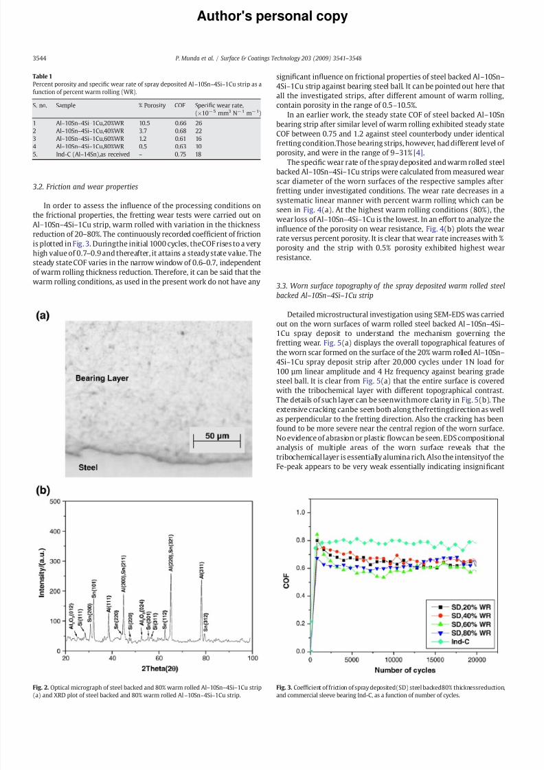
8182019 Munda Wear
httpslidepdfcomreaderfullmunda-wear 59
Authors personal copy
32 Friction and wear properties
In order to assess the in1047298uence of the processing conditions on
the frictional properties the fretting wear tests were carried out on
Alndash10Snndash4Sindash1Cu strip warm rolled with variation in the thickness
reduction of 20ndash80 The continuously recorded coef 1047297cient of friction
is plotted in Fig 3 Duringthe initial 1000 cycles theCOF rises to a very
high value of 07ndash09 and thereafter it attains a steady state value The
steady state COF varies in the narrow window of 06ndash07 independent
of warm rolling thickness reduction Therefore it can be said that thewarm rolling conditions as used in the present work do not have any
signi1047297cant in1047298uence on frictional properties of steel backed Alndash10Snndash
4Sindash1Cu strip against bearing steel ball It can be pointed out here that
all the investigated strips after different amount of warm rolling
contain porosity in the range of 05ndash105
In an earlier work the steady state COF of steel backed Alndash10Sn
bearing strip after similar level of warm rolling exhibited steady state
COF between 075 and 12 against steel counterbody under identicalfretting conditionThose bearing strips however had different level of
porosity and were in the range of 9ndash31 [4]
The speci1047297c wear rate of the spray deposited and warm rolled steel
backed Alndash10Snndash4Sindash1Cu strips were calculated from measured wear
scar diameter of the worn surfaces of the respective samples after
fretting under investigated conditions The wear rate decreases in a
systematic linear manner with percent warm rolling which can be
seen in Fig 4(a) At the highest warm rolling conditions (80) the
wear loss of Alndash10Snndash4Sindash1Cu is the lowest In an effort to analyze the
in1047298uence of the porosity on wear resistance Fig 4(b) plots the wear
rate versus percent porosity It is clear that wear rate increases with
porosity and the strip with 05 porosity exhibited highest wear
resistance
33 Worn surface topography of the spray deposited warm rolled steel
backed Alndash10Snndash4Sindash1Cu strip
Detailed microstructural investigation using SEM-EDS was carried
out on the worn surfaces of warm rolled steel backed Alndash10Snndash4Sindash
1Cu spray deposit to understand the mechanism governing the
fretting wear Fig 5(a) displays the overall topographical features of
the worn scar formed on the surface of the 20 warm rolled Alndash10Snndash
4Sindash1Cu spray deposit strip after 20000 cycles under 1N load for
100 microm linear amplitude and 4 Hz frequency against bearing grade
steel ball It is clear from Fig 5(a) that the entire surface is covered
with the tribochemical layer with different topographical contrast
The details of such layer can be seenwithmore clarity in Fig 5(b) The
extensive cracking canbe seen both along thefrettingdirection as well
as perpendicular to the fretting direction Also the cracking has been
found to be more severe near the central region of the worn surface
No evidence of abrasion or plastic 1047298owcan be seen EDS compositional
analysis of multiple areas of the worn surface reveals that the
tribochemical layer is essentially alumina rich Also the intensityof the
Fe-peak appears to be very weak essentially indicating insigni1047297cant
Table 1
Percent porosity and speci1047297c wear rate of spray deposited Alndash10Snndash4Sindash1Cu strip as a
function of percent warm rolling (WR)
S no Sample Porosity COF Speci1047297c wear rate
(times10minus5 mm3 Nminus1 mminus1)
1 Alndash10Snndash4Sindash1Cu20WR 105 066 26
2 Alndash10Snndash4Sindash1Cu40WR 37 068 22
3 Alndash10Snndash4Sindash1Cu60WR 12 061 16
4 Alndash10Snndash4Sindash1Cu80WR 05 063 10
5 Ind-C (Alndash14Sn)as received ndash 075 18
Fig 2 Optical micrograph of steel backed and 80 warm rolled Alndash10Snndash4Sindash1Cu strip
(a) and XRD plot of steel backed and 80 warm rolled Alndash10Snndash4Sindash1Cu strip
Fig 3 Coef 1047297cient of friction of spray deposited(SD) steel backed80 thicknessreduction
and commercial sleeve bearing Ind-C as a function of number of cycles
3544 P Munda et al Surface amp Coatings Technology 203 (2009) 3541ndash 3548
8182019 Munda Wear
httpslidepdfcomreaderfullmunda-wear 69
Authors personal copy
transfer of materials from mating counterbody (steel ball) One
representative EDS spectrum is provided in the inset of Fig 5(b)
When the same metallic strip after 40 warm rolling is fretted
under identical conditions we observed much extensive cracking of
the tribochemical layer throughout the worn surface Also a largeamount of wear debris particles (both 1047297ner in size as well as
agglomerated) are found around the periphery of the worn surface
The details of the wear debris particles in terms of size and shape can
be seenin the inset of Fig 6(a) Largely thewear debrisparticles areof
submicron size with few agglomerated irregular shaped debris
particles appearing in sizes of less than 10 microm Again EDS composi-
tional analysiscon1047297rms[inset of Fig6(b)] thepresence of alumina rich
tribochemical layer The fragmentation of the tribochemical layers can
be clearly seen in Fig 6(b) It is easy to realize that during continuous
fretting process a number of fragmented parts of tribochemical layer
with sizes in the range of 50ndash100 micromcan beeasilyspalled and thiswill
lead to the subsequent wear of the underlying material
In case of the same Alndash10Snndash4Sindash1Cu based metallic strip after 60
warm rolling similar topographical features are clearly observed [seeFig 7(a)] Thedetailed topographical observations as shown in Fig 7(b)
reveal the extensive occurrence of cracking A comparison of Fig 7(b)
with Fig 6(b) however con1047297rms that the severity of fretting induced
damage is noticeably reduced as the percent warm rolling increased
from 40 to 60
Fig 8(a) and (b) show typical SEM images showing overall
topography of worm surfaces of the metallic strip with the highest
percent warm rolling (80) The worn surface exhibits even much less
cracking induced damage mechanism [see brighter contrast area inFig 8(a)] The major part of the worn surface is however covered with
tribolayer Also signi1047297cant amount of 1047297ner and agglomerated debris
particles are observed in the regions adjacent to the edges of wear
scar Like in other cases the amount of Fe transfer to worn surface is
minimum
From the above observations it should be clear that oxidative
wear and cracking of the tribochemical layer are the major wear
Fig 4 Speci1047297c wear rate of Alndash10Snndash4Sindash1Cu as function of percent warm rolling (a)
and percent porosity (b)
Fig 5 Typical SEM images at different magni1047297
cations showing overall topography of worn surfaces of spray deposited and 20 warm rolled Alndash10Snndash4Sindash1Cu strip fretting
conditions-20000 cycles 4 Hz frequency100 microm stroke length counter body bearing
steel arrows indicate fretting direction
3545P Munda et al Surface amp Coatings Technology 203 (2009) 3541ndash 3548
8182019 Munda Wear
httpslidepdfcomreaderfullmunda-wear 79
Authors personal copy
mechanisms Duringthe initial stageAl is oxidizedto form Al2O3 layer
During repeated fretting stroke Al2O3 rich tribolayer cracks and a
number of cracked islands of wear fragments are formed The obser-
vation of large amount of wear debris particles around the wear scar
periphery indicates that such debris particles are formed due to re-
peated fracturing of suchwear fragmentsand subsequently ejected out
from the tribological interface
34 Comparison of the tribological behavior of the present material with
that of other materials
The tribological behavior of the spray deposited and warm rolled
steel backed Alndash10Snndash4Sindash1Cu strip was compared with that of sleeve
bearing material (designated as Ind-C) used widely in an Indian car
The EDS analysis of the bearing layer showed that it was basically
aluminum-based having approximately 14ndash15 wt tin as the major
alloying element Fig 3 also plots the continuously recorded
coef 1047297cient of friction of the Ind-C material During the initial
1000 cycles the COF rises to a high value of 08 and thereafter it
attains a steady state value The steady state COF varies in the narrow
range of 07ndash08 having an average value of 075 The speci1047297c wear
rate of the Ind-C material was found to be 18times10minus5 mm3 Nminus1mminus1 It
can be seen that the COF value and the speci1047297c wear rate of the Ind-C
material is greater than that of the spray deposited and 80 warm
rolled steel backed Alndash10Snndash4Sindash1Cu strip (containing 05 porosity)
used in the present study Thecorrespondingvalueof average COFand
speci1047297c wear ratewere 063 and 10times 10minus5 mm3 Nminus1mminus1 respectively
(Table 1)Fig9(a) shows representative SEM image of the overall topography
of the worn surface formed on the Ind-C material after 20000 cycles
Fig 6 Typical SEM images at different magni1047297
cations showing overall topography of worn surfaces of spray deposited and 40 warm rolled Alndash10Snndash4Sindash1Cu strip fretting
conditions-20000 cycles 4 Hz frequency100 microm stroke length counter body bearing
steel arrows indicate fretting direction
Fig 7 Typical SEM images at different magni1047297cations showing overall topography of
worn surfaces of spray deposited and 60 warm rolled Alndash10Snndash4Sindash1Cu strip fretting
conditions-20000 cycles 4 Hz frequency100 microm stroke length counter body bearing
steel arrows indicate fretting direction
3546 P Munda et al Surface amp Coatings Technology 203 (2009) 3541ndash 3548
8182019 Munda Wear
httpslidepdfcomreaderfullmunda-wear 89
Authors personal copy
under 1N load for 100 microm linearamplitude and 4 Hz frequency against
bearing grade steel ball It is clear that thecommercial bearing material
experiences extensive tribochemical wear More signi1047297cantly large
amount of coarsesheet like wear debrisparticles arefound to disperse
around wear scar edge Also 1047297ner wear debris particles are also
observed The details of the tribological layer formed on the surface can
be seen more clearly in Fig 9(b) Extensive cracking of the
tribochemical layer along with severe fragmentation of tribochemical
layer are evident EDS analysis con1047297rms that tribochemical layer is
essentially oxide rich The amount of steel transfer to 1047298at is negligible
The implication of the present work is important In our earlier
work we reported the tribological properties of Alndash10Sn metallic strip
under identical fretting conditions One of the important results was
that Alndash10Sn alloy when warm rolled 75thickness reductionexhibits high COF of 09This material was prepared using the same
approach as used for steel backed Alndash10Snndash4Sindash1Cu bearing strip [4]
The present work demonstrates that suitable alloy design ap-
proach can enable us to develop better metallic strip of Alndash10Snndash4Sindash
1Cu composition having a lower of COF of 063 From the aspect of real
applications any tribological material experiencing lower friction is
always preferred This is due to the fact that the dissipated energy will
be lower in case of material combinations with lower COF and as a
result lower energy needs to be supplied from external source tomaintain relative motion at the tribological interface On the basis of
the present study it should be clear that the WR-80 sample should be
preferred over commercial sleeve bearing alloy (Ind-C sample) for
given automotive applications This will ensure longer durability cou-
pled with energy savings as well as from economic aspect (less fre-
quent replacement)
Theadvantage forthe useof Alndash10Snndash4Sindash1Cualloyoverthe Alndash10Sn
alloy produced via the same processing route can also be mentioned
Fig 8 Typical SEM images at different magni1047297cations showing overall topography of
worn surfaces of spray deposited and 20 warm rolled Alndash10Snndash4Sindash1Cu strip fretting
conditionsmdash20000 cycles 4 Hz frequency100 microm stroke length counter body bearing
steel arrows indicate fretting direction
Fig 9 Typical SEM images at different magni1047297
cations showing overall topography of worn surfaces of AlndashSn commercial sleeve bearing (Ind-C) fretting conditionsmdash
20000 cycles 4 Hz frequency 100 microm stroke length counter body bearing steel
arrows indicate fretting direction
3547P Munda et al Surface amp Coatings Technology 203 (2009) 3541ndash 3548
8182019 Munda Wear
httpslidepdfcomreaderfullmunda-wear 99
Authors personal copy
fromthe processingaspect Fromthe manufacturing aspect the addition
of Si enhances the 1047298uidity of the melt and thereby ensures a moredense
spray deposit of the bearing layer on the steel substrate As a result steel
backed Alndash10Snndash4Sindash1Cu bearing alloy strip will require less amount of
warm rolling for achieving near full density in the bearing layer as
compared to steel backed Alndash10Sn bearing alloy strip produced under
identical condition of spray deposition and rolling
4 Conclusions
In the present work the steel backed and warm rolled Alndash10Snndash
4Sindash1Cu metallic strips were fretted against bearing steel Based on
our experimental observations the following conclusions are drawn
a No signi1047297cant difference in terms of the frictional behavior was
observed when the metallic strips warm rolled to varying thick-
ness reductions of up to 80 were subjected to fretting wear
against steel Independent of warm rolling conditions the steady
state COF varies in the narrow window of 06ndash07
b The speci1047297c wear rate decreases in a systematic linear manner
with percentage warm rolling of spray atomized layer The wear
rate of 80 warm rolled steel backed Alndash10Snndash4Sindash1Cu strip wasfound to be 10times10minus5 mm3Nminus1mminus1
c The tribooxidation is the dominant wear mechanism and the
formation of alumina rich tribolayer is observed irrespective of
warm rolling conditions The cracking of tribolayer and signi1047297cant
wear debris (both submicron and agglomerated) formation are
found to be additional mechanisms
d The COF of the spray deposited and 80 warm rolled steel backed
Alndash10Snndash4Sindash1Cu stripshas beenfound to belowerthan thatof the
spray deposited Alndash10Sn composition subjected to similar amount
of warm rolling
e The COF value and the speci1047297c wear rate of the present materialwarmrolled to80 has beenfoundto belowerthan thatof a typical
steel backed AlndashSn bearing alloy strip used in a commercially pro-
duced Indian passenger car
References
[1] ARE Singer Met Mater 4 (1970) 246[2] MR Tripathy Properties of steel backed AlndashSn strip prepared via spray atomizationndash
deposition-rolling route MTech dissertation Indian Institute of Technology KanpurIndia 2005
[3] MR Tripathy RK Dube SC Koria J Mater Process Technol 190 (2007) 342[4] MR Tripathy BV Manoj Kumar B Basu RK Dube SC Koria Mater Sci Technol
23 (2007) 15[5] T Desaki S Kamiya K Sato Y Okauchi and T Nukami Aluminum alloy for sliding
bearing and its production method US Patent no6 706126 B2 Mar 16 2004[6] IM Hutchings Tribology Friction and Wearof Engineering Materials Edward Arnold
London 1992[7] O Vingsbo S Stierberg Wear 126 (1988) 131[8] AD Sarkar Friction and Wear Academic Press London 1980[9] D Klaffke Tribol Int 22 (2) (1989) 89
3548 P Munda et al Surface amp Coatings Technology 203 (2009) 3541ndash 3548
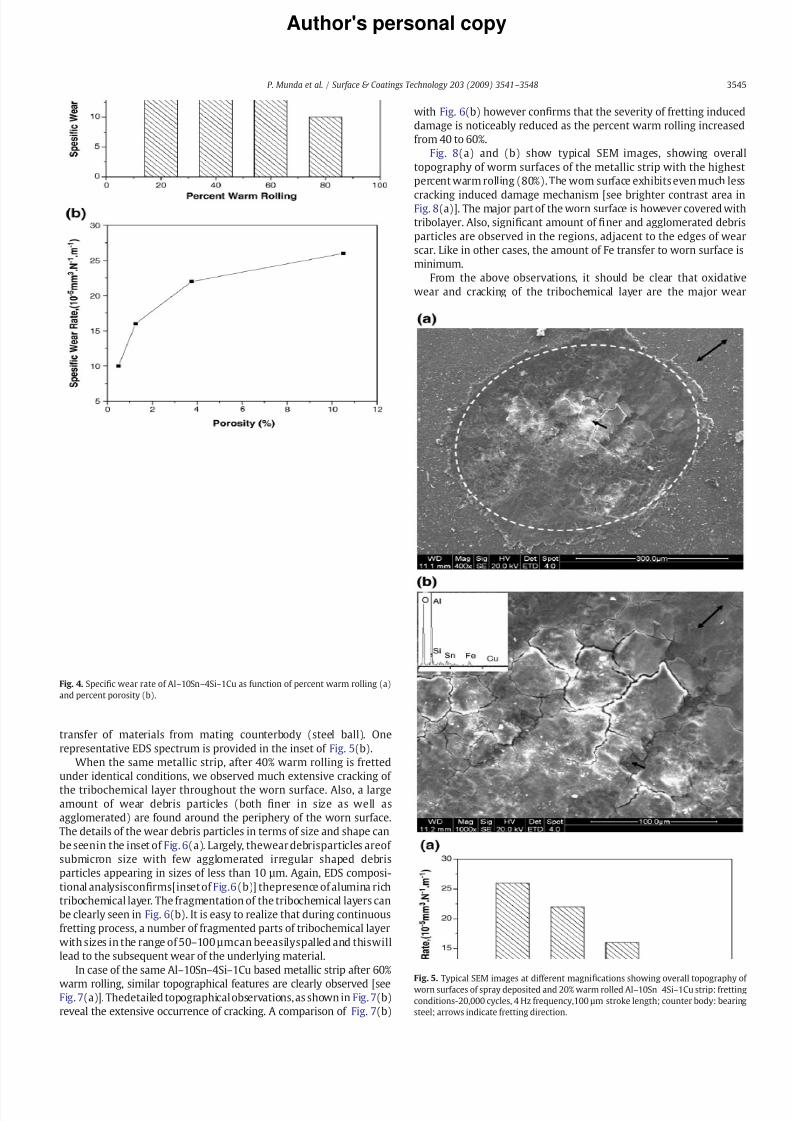
8182019 Munda Wear
httpslidepdfcomreaderfullmunda-wear 69
Authors personal copy
transfer of materials from mating counterbody (steel ball) One
representative EDS spectrum is provided in the inset of Fig 5(b)
When the same metallic strip after 40 warm rolling is fretted
under identical conditions we observed much extensive cracking of
the tribochemical layer throughout the worn surface Also a largeamount of wear debris particles (both 1047297ner in size as well as
agglomerated) are found around the periphery of the worn surface
The details of the wear debris particles in terms of size and shape can
be seenin the inset of Fig 6(a) Largely thewear debrisparticles areof
submicron size with few agglomerated irregular shaped debris
particles appearing in sizes of less than 10 microm Again EDS composi-
tional analysiscon1047297rms[inset of Fig6(b)] thepresence of alumina rich
tribochemical layer The fragmentation of the tribochemical layers can
be clearly seen in Fig 6(b) It is easy to realize that during continuous
fretting process a number of fragmented parts of tribochemical layer
with sizes in the range of 50ndash100 micromcan beeasilyspalled and thiswill
lead to the subsequent wear of the underlying material
In case of the same Alndash10Snndash4Sindash1Cu based metallic strip after 60
warm rolling similar topographical features are clearly observed [seeFig 7(a)] Thedetailed topographical observations as shown in Fig 7(b)
reveal the extensive occurrence of cracking A comparison of Fig 7(b)
with Fig 6(b) however con1047297rms that the severity of fretting induced
damage is noticeably reduced as the percent warm rolling increased
from 40 to 60
Fig 8(a) and (b) show typical SEM images showing overall
topography of worm surfaces of the metallic strip with the highest
percent warm rolling (80) The worn surface exhibits even much less
cracking induced damage mechanism [see brighter contrast area inFig 8(a)] The major part of the worn surface is however covered with
tribolayer Also signi1047297cant amount of 1047297ner and agglomerated debris
particles are observed in the regions adjacent to the edges of wear
scar Like in other cases the amount of Fe transfer to worn surface is
minimum
From the above observations it should be clear that oxidative
wear and cracking of the tribochemical layer are the major wear
Fig 4 Speci1047297c wear rate of Alndash10Snndash4Sindash1Cu as function of percent warm rolling (a)
and percent porosity (b)
Fig 5 Typical SEM images at different magni1047297
cations showing overall topography of worn surfaces of spray deposited and 20 warm rolled Alndash10Snndash4Sindash1Cu strip fretting
conditions-20000 cycles 4 Hz frequency100 microm stroke length counter body bearing
steel arrows indicate fretting direction
3545P Munda et al Surface amp Coatings Technology 203 (2009) 3541ndash 3548
8182019 Munda Wear
httpslidepdfcomreaderfullmunda-wear 79
Authors personal copy
mechanisms Duringthe initial stageAl is oxidizedto form Al2O3 layer
During repeated fretting stroke Al2O3 rich tribolayer cracks and a
number of cracked islands of wear fragments are formed The obser-
vation of large amount of wear debris particles around the wear scar
periphery indicates that such debris particles are formed due to re-
peated fracturing of suchwear fragmentsand subsequently ejected out
from the tribological interface
34 Comparison of the tribological behavior of the present material with
that of other materials
The tribological behavior of the spray deposited and warm rolled
steel backed Alndash10Snndash4Sindash1Cu strip was compared with that of sleeve
bearing material (designated as Ind-C) used widely in an Indian car
The EDS analysis of the bearing layer showed that it was basically
aluminum-based having approximately 14ndash15 wt tin as the major
alloying element Fig 3 also plots the continuously recorded
coef 1047297cient of friction of the Ind-C material During the initial
1000 cycles the COF rises to a high value of 08 and thereafter it
attains a steady state value The steady state COF varies in the narrow
range of 07ndash08 having an average value of 075 The speci1047297c wear
rate of the Ind-C material was found to be 18times10minus5 mm3 Nminus1mminus1 It
can be seen that the COF value and the speci1047297c wear rate of the Ind-C
material is greater than that of the spray deposited and 80 warm
rolled steel backed Alndash10Snndash4Sindash1Cu strip (containing 05 porosity)
used in the present study Thecorrespondingvalueof average COFand
speci1047297c wear ratewere 063 and 10times 10minus5 mm3 Nminus1mminus1 respectively
(Table 1)Fig9(a) shows representative SEM image of the overall topography
of the worn surface formed on the Ind-C material after 20000 cycles
Fig 6 Typical SEM images at different magni1047297
cations showing overall topography of worn surfaces of spray deposited and 40 warm rolled Alndash10Snndash4Sindash1Cu strip fretting
conditions-20000 cycles 4 Hz frequency100 microm stroke length counter body bearing
steel arrows indicate fretting direction
Fig 7 Typical SEM images at different magni1047297cations showing overall topography of
worn surfaces of spray deposited and 60 warm rolled Alndash10Snndash4Sindash1Cu strip fretting
conditions-20000 cycles 4 Hz frequency100 microm stroke length counter body bearing
steel arrows indicate fretting direction
3546 P Munda et al Surface amp Coatings Technology 203 (2009) 3541ndash 3548
8182019 Munda Wear
httpslidepdfcomreaderfullmunda-wear 89
Authors personal copy
under 1N load for 100 microm linearamplitude and 4 Hz frequency against
bearing grade steel ball It is clear that thecommercial bearing material
experiences extensive tribochemical wear More signi1047297cantly large
amount of coarsesheet like wear debrisparticles arefound to disperse
around wear scar edge Also 1047297ner wear debris particles are also
observed The details of the tribological layer formed on the surface can
be seen more clearly in Fig 9(b) Extensive cracking of the
tribochemical layer along with severe fragmentation of tribochemical
layer are evident EDS analysis con1047297rms that tribochemical layer is
essentially oxide rich The amount of steel transfer to 1047298at is negligible
The implication of the present work is important In our earlier
work we reported the tribological properties of Alndash10Sn metallic strip
under identical fretting conditions One of the important results was
that Alndash10Sn alloy when warm rolled 75thickness reductionexhibits high COF of 09This material was prepared using the same
approach as used for steel backed Alndash10Snndash4Sindash1Cu bearing strip [4]
The present work demonstrates that suitable alloy design ap-
proach can enable us to develop better metallic strip of Alndash10Snndash4Sindash
1Cu composition having a lower of COF of 063 From the aspect of real
applications any tribological material experiencing lower friction is
always preferred This is due to the fact that the dissipated energy will
be lower in case of material combinations with lower COF and as a
result lower energy needs to be supplied from external source tomaintain relative motion at the tribological interface On the basis of
the present study it should be clear that the WR-80 sample should be
preferred over commercial sleeve bearing alloy (Ind-C sample) for
given automotive applications This will ensure longer durability cou-
pled with energy savings as well as from economic aspect (less fre-
quent replacement)
Theadvantage forthe useof Alndash10Snndash4Sindash1Cualloyoverthe Alndash10Sn
alloy produced via the same processing route can also be mentioned
Fig 8 Typical SEM images at different magni1047297cations showing overall topography of
worn surfaces of spray deposited and 20 warm rolled Alndash10Snndash4Sindash1Cu strip fretting
conditionsmdash20000 cycles 4 Hz frequency100 microm stroke length counter body bearing
steel arrows indicate fretting direction
Fig 9 Typical SEM images at different magni1047297
cations showing overall topography of worn surfaces of AlndashSn commercial sleeve bearing (Ind-C) fretting conditionsmdash
20000 cycles 4 Hz frequency 100 microm stroke length counter body bearing steel
arrows indicate fretting direction
3547P Munda et al Surface amp Coatings Technology 203 (2009) 3541ndash 3548
8182019 Munda Wear
httpslidepdfcomreaderfullmunda-wear 99
Authors personal copy
fromthe processingaspect Fromthe manufacturing aspect the addition
of Si enhances the 1047298uidity of the melt and thereby ensures a moredense
spray deposit of the bearing layer on the steel substrate As a result steel
backed Alndash10Snndash4Sindash1Cu bearing alloy strip will require less amount of
warm rolling for achieving near full density in the bearing layer as
compared to steel backed Alndash10Sn bearing alloy strip produced under
identical condition of spray deposition and rolling
4 Conclusions
In the present work the steel backed and warm rolled Alndash10Snndash
4Sindash1Cu metallic strips were fretted against bearing steel Based on
our experimental observations the following conclusions are drawn
a No signi1047297cant difference in terms of the frictional behavior was
observed when the metallic strips warm rolled to varying thick-
ness reductions of up to 80 were subjected to fretting wear
against steel Independent of warm rolling conditions the steady
state COF varies in the narrow window of 06ndash07
b The speci1047297c wear rate decreases in a systematic linear manner
with percentage warm rolling of spray atomized layer The wear
rate of 80 warm rolled steel backed Alndash10Snndash4Sindash1Cu strip wasfound to be 10times10minus5 mm3Nminus1mminus1
c The tribooxidation is the dominant wear mechanism and the
formation of alumina rich tribolayer is observed irrespective of
warm rolling conditions The cracking of tribolayer and signi1047297cant
wear debris (both submicron and agglomerated) formation are
found to be additional mechanisms
d The COF of the spray deposited and 80 warm rolled steel backed
Alndash10Snndash4Sindash1Cu stripshas beenfound to belowerthan thatof the
spray deposited Alndash10Sn composition subjected to similar amount
of warm rolling
e The COF value and the speci1047297c wear rate of the present materialwarmrolled to80 has beenfoundto belowerthan thatof a typical
steel backed AlndashSn bearing alloy strip used in a commercially pro-
duced Indian passenger car
References
[1] ARE Singer Met Mater 4 (1970) 246[2] MR Tripathy Properties of steel backed AlndashSn strip prepared via spray atomizationndash
deposition-rolling route MTech dissertation Indian Institute of Technology KanpurIndia 2005
[3] MR Tripathy RK Dube SC Koria J Mater Process Technol 190 (2007) 342[4] MR Tripathy BV Manoj Kumar B Basu RK Dube SC Koria Mater Sci Technol
23 (2007) 15[5] T Desaki S Kamiya K Sato Y Okauchi and T Nukami Aluminum alloy for sliding
bearing and its production method US Patent no6 706126 B2 Mar 16 2004[6] IM Hutchings Tribology Friction and Wearof Engineering Materials Edward Arnold
London 1992[7] O Vingsbo S Stierberg Wear 126 (1988) 131[8] AD Sarkar Friction and Wear Academic Press London 1980[9] D Klaffke Tribol Int 22 (2) (1989) 89
3548 P Munda et al Surface amp Coatings Technology 203 (2009) 3541ndash 3548
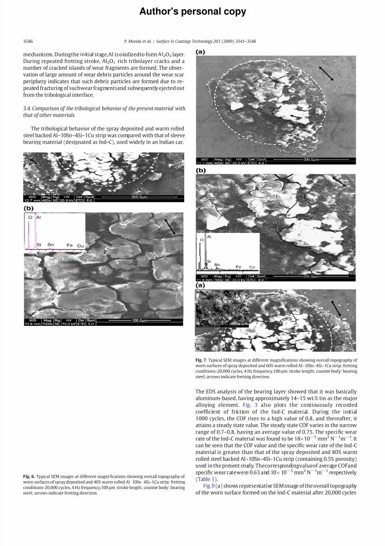
8182019 Munda Wear
httpslidepdfcomreaderfullmunda-wear 79
Authors personal copy
mechanisms Duringthe initial stageAl is oxidizedto form Al2O3 layer
During repeated fretting stroke Al2O3 rich tribolayer cracks and a
number of cracked islands of wear fragments are formed The obser-
vation of large amount of wear debris particles around the wear scar
periphery indicates that such debris particles are formed due to re-
peated fracturing of suchwear fragmentsand subsequently ejected out
from the tribological interface
34 Comparison of the tribological behavior of the present material with
that of other materials
The tribological behavior of the spray deposited and warm rolled
steel backed Alndash10Snndash4Sindash1Cu strip was compared with that of sleeve
bearing material (designated as Ind-C) used widely in an Indian car
The EDS analysis of the bearing layer showed that it was basically
aluminum-based having approximately 14ndash15 wt tin as the major
alloying element Fig 3 also plots the continuously recorded
coef 1047297cient of friction of the Ind-C material During the initial
1000 cycles the COF rises to a high value of 08 and thereafter it
attains a steady state value The steady state COF varies in the narrow
range of 07ndash08 having an average value of 075 The speci1047297c wear
rate of the Ind-C material was found to be 18times10minus5 mm3 Nminus1mminus1 It
can be seen that the COF value and the speci1047297c wear rate of the Ind-C
material is greater than that of the spray deposited and 80 warm
rolled steel backed Alndash10Snndash4Sindash1Cu strip (containing 05 porosity)
used in the present study Thecorrespondingvalueof average COFand
speci1047297c wear ratewere 063 and 10times 10minus5 mm3 Nminus1mminus1 respectively
(Table 1)Fig9(a) shows representative SEM image of the overall topography
of the worn surface formed on the Ind-C material after 20000 cycles
Fig 6 Typical SEM images at different magni1047297
cations showing overall topography of worn surfaces of spray deposited and 40 warm rolled Alndash10Snndash4Sindash1Cu strip fretting
conditions-20000 cycles 4 Hz frequency100 microm stroke length counter body bearing
steel arrows indicate fretting direction
Fig 7 Typical SEM images at different magni1047297cations showing overall topography of
worn surfaces of spray deposited and 60 warm rolled Alndash10Snndash4Sindash1Cu strip fretting
conditions-20000 cycles 4 Hz frequency100 microm stroke length counter body bearing
steel arrows indicate fretting direction
3546 P Munda et al Surface amp Coatings Technology 203 (2009) 3541ndash 3548
8182019 Munda Wear
httpslidepdfcomreaderfullmunda-wear 89
Authors personal copy
under 1N load for 100 microm linearamplitude and 4 Hz frequency against
bearing grade steel ball It is clear that thecommercial bearing material
experiences extensive tribochemical wear More signi1047297cantly large
amount of coarsesheet like wear debrisparticles arefound to disperse
around wear scar edge Also 1047297ner wear debris particles are also
observed The details of the tribological layer formed on the surface can
be seen more clearly in Fig 9(b) Extensive cracking of the
tribochemical layer along with severe fragmentation of tribochemical
layer are evident EDS analysis con1047297rms that tribochemical layer is
essentially oxide rich The amount of steel transfer to 1047298at is negligible
The implication of the present work is important In our earlier
work we reported the tribological properties of Alndash10Sn metallic strip
under identical fretting conditions One of the important results was
that Alndash10Sn alloy when warm rolled 75thickness reductionexhibits high COF of 09This material was prepared using the same
approach as used for steel backed Alndash10Snndash4Sindash1Cu bearing strip [4]
The present work demonstrates that suitable alloy design ap-
proach can enable us to develop better metallic strip of Alndash10Snndash4Sindash
1Cu composition having a lower of COF of 063 From the aspect of real
applications any tribological material experiencing lower friction is
always preferred This is due to the fact that the dissipated energy will
be lower in case of material combinations with lower COF and as a
result lower energy needs to be supplied from external source tomaintain relative motion at the tribological interface On the basis of
the present study it should be clear that the WR-80 sample should be
preferred over commercial sleeve bearing alloy (Ind-C sample) for
given automotive applications This will ensure longer durability cou-
pled with energy savings as well as from economic aspect (less fre-
quent replacement)
Theadvantage forthe useof Alndash10Snndash4Sindash1Cualloyoverthe Alndash10Sn
alloy produced via the same processing route can also be mentioned
Fig 8 Typical SEM images at different magni1047297cations showing overall topography of
worn surfaces of spray deposited and 20 warm rolled Alndash10Snndash4Sindash1Cu strip fretting
conditionsmdash20000 cycles 4 Hz frequency100 microm stroke length counter body bearing
steel arrows indicate fretting direction
Fig 9 Typical SEM images at different magni1047297
cations showing overall topography of worn surfaces of AlndashSn commercial sleeve bearing (Ind-C) fretting conditionsmdash
20000 cycles 4 Hz frequency 100 microm stroke length counter body bearing steel
arrows indicate fretting direction
3547P Munda et al Surface amp Coatings Technology 203 (2009) 3541ndash 3548
8182019 Munda Wear
httpslidepdfcomreaderfullmunda-wear 99
Authors personal copy
fromthe processingaspect Fromthe manufacturing aspect the addition
of Si enhances the 1047298uidity of the melt and thereby ensures a moredense
spray deposit of the bearing layer on the steel substrate As a result steel
backed Alndash10Snndash4Sindash1Cu bearing alloy strip will require less amount of
warm rolling for achieving near full density in the bearing layer as
compared to steel backed Alndash10Sn bearing alloy strip produced under
identical condition of spray deposition and rolling
4 Conclusions
In the present work the steel backed and warm rolled Alndash10Snndash
4Sindash1Cu metallic strips were fretted against bearing steel Based on
our experimental observations the following conclusions are drawn
a No signi1047297cant difference in terms of the frictional behavior was
observed when the metallic strips warm rolled to varying thick-
ness reductions of up to 80 were subjected to fretting wear
against steel Independent of warm rolling conditions the steady
state COF varies in the narrow window of 06ndash07
b The speci1047297c wear rate decreases in a systematic linear manner
with percentage warm rolling of spray atomized layer The wear
rate of 80 warm rolled steel backed Alndash10Snndash4Sindash1Cu strip wasfound to be 10times10minus5 mm3Nminus1mminus1
c The tribooxidation is the dominant wear mechanism and the
formation of alumina rich tribolayer is observed irrespective of
warm rolling conditions The cracking of tribolayer and signi1047297cant
wear debris (both submicron and agglomerated) formation are
found to be additional mechanisms
d The COF of the spray deposited and 80 warm rolled steel backed
Alndash10Snndash4Sindash1Cu stripshas beenfound to belowerthan thatof the
spray deposited Alndash10Sn composition subjected to similar amount
of warm rolling
e The COF value and the speci1047297c wear rate of the present materialwarmrolled to80 has beenfoundto belowerthan thatof a typical
steel backed AlndashSn bearing alloy strip used in a commercially pro-
duced Indian passenger car
References
[1] ARE Singer Met Mater 4 (1970) 246[2] MR Tripathy Properties of steel backed AlndashSn strip prepared via spray atomizationndash
deposition-rolling route MTech dissertation Indian Institute of Technology KanpurIndia 2005
[3] MR Tripathy RK Dube SC Koria J Mater Process Technol 190 (2007) 342[4] MR Tripathy BV Manoj Kumar B Basu RK Dube SC Koria Mater Sci Technol
23 (2007) 15[5] T Desaki S Kamiya K Sato Y Okauchi and T Nukami Aluminum alloy for sliding
bearing and its production method US Patent no6 706126 B2 Mar 16 2004[6] IM Hutchings Tribology Friction and Wearof Engineering Materials Edward Arnold
London 1992[7] O Vingsbo S Stierberg Wear 126 (1988) 131[8] AD Sarkar Friction and Wear Academic Press London 1980[9] D Klaffke Tribol Int 22 (2) (1989) 89
3548 P Munda et al Surface amp Coatings Technology 203 (2009) 3541ndash 3548
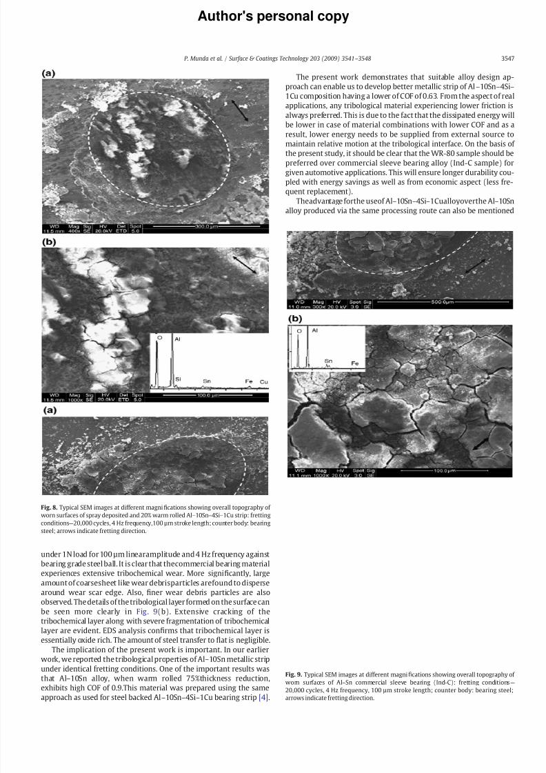
8182019 Munda Wear
httpslidepdfcomreaderfullmunda-wear 89
Authors personal copy
under 1N load for 100 microm linearamplitude and 4 Hz frequency against
bearing grade steel ball It is clear that thecommercial bearing material
experiences extensive tribochemical wear More signi1047297cantly large
amount of coarsesheet like wear debrisparticles arefound to disperse
around wear scar edge Also 1047297ner wear debris particles are also
observed The details of the tribological layer formed on the surface can
be seen more clearly in Fig 9(b) Extensive cracking of the
tribochemical layer along with severe fragmentation of tribochemical
layer are evident EDS analysis con1047297rms that tribochemical layer is
essentially oxide rich The amount of steel transfer to 1047298at is negligible
The implication of the present work is important In our earlier
work we reported the tribological properties of Alndash10Sn metallic strip
under identical fretting conditions One of the important results was
that Alndash10Sn alloy when warm rolled 75thickness reductionexhibits high COF of 09This material was prepared using the same
approach as used for steel backed Alndash10Snndash4Sindash1Cu bearing strip [4]
The present work demonstrates that suitable alloy design ap-
proach can enable us to develop better metallic strip of Alndash10Snndash4Sindash
1Cu composition having a lower of COF of 063 From the aspect of real
applications any tribological material experiencing lower friction is
always preferred This is due to the fact that the dissipated energy will
be lower in case of material combinations with lower COF and as a
result lower energy needs to be supplied from external source tomaintain relative motion at the tribological interface On the basis of
the present study it should be clear that the WR-80 sample should be
preferred over commercial sleeve bearing alloy (Ind-C sample) for
given automotive applications This will ensure longer durability cou-
pled with energy savings as well as from economic aspect (less fre-
quent replacement)
Theadvantage forthe useof Alndash10Snndash4Sindash1Cualloyoverthe Alndash10Sn
alloy produced via the same processing route can also be mentioned
Fig 8 Typical SEM images at different magni1047297cations showing overall topography of
worn surfaces of spray deposited and 20 warm rolled Alndash10Snndash4Sindash1Cu strip fretting
conditionsmdash20000 cycles 4 Hz frequency100 microm stroke length counter body bearing
steel arrows indicate fretting direction
Fig 9 Typical SEM images at different magni1047297
cations showing overall topography of worn surfaces of AlndashSn commercial sleeve bearing (Ind-C) fretting conditionsmdash
20000 cycles 4 Hz frequency 100 microm stroke length counter body bearing steel
arrows indicate fretting direction
3547P Munda et al Surface amp Coatings Technology 203 (2009) 3541ndash 3548
8182019 Munda Wear
httpslidepdfcomreaderfullmunda-wear 99
Authors personal copy
fromthe processingaspect Fromthe manufacturing aspect the addition
of Si enhances the 1047298uidity of the melt and thereby ensures a moredense
spray deposit of the bearing layer on the steel substrate As a result steel
backed Alndash10Snndash4Sindash1Cu bearing alloy strip will require less amount of
warm rolling for achieving near full density in the bearing layer as
compared to steel backed Alndash10Sn bearing alloy strip produced under
identical condition of spray deposition and rolling
4 Conclusions
In the present work the steel backed and warm rolled Alndash10Snndash
4Sindash1Cu metallic strips were fretted against bearing steel Based on
our experimental observations the following conclusions are drawn
a No signi1047297cant difference in terms of the frictional behavior was
observed when the metallic strips warm rolled to varying thick-
ness reductions of up to 80 were subjected to fretting wear
against steel Independent of warm rolling conditions the steady
state COF varies in the narrow window of 06ndash07
b The speci1047297c wear rate decreases in a systematic linear manner
with percentage warm rolling of spray atomized layer The wear
rate of 80 warm rolled steel backed Alndash10Snndash4Sindash1Cu strip wasfound to be 10times10minus5 mm3Nminus1mminus1
c The tribooxidation is the dominant wear mechanism and the
formation of alumina rich tribolayer is observed irrespective of
warm rolling conditions The cracking of tribolayer and signi1047297cant
wear debris (both submicron and agglomerated) formation are
found to be additional mechanisms
d The COF of the spray deposited and 80 warm rolled steel backed
Alndash10Snndash4Sindash1Cu stripshas beenfound to belowerthan thatof the
spray deposited Alndash10Sn composition subjected to similar amount
of warm rolling
e The COF value and the speci1047297c wear rate of the present materialwarmrolled to80 has beenfoundto belowerthan thatof a typical
steel backed AlndashSn bearing alloy strip used in a commercially pro-
duced Indian passenger car
References
[1] ARE Singer Met Mater 4 (1970) 246[2] MR Tripathy Properties of steel backed AlndashSn strip prepared via spray atomizationndash
deposition-rolling route MTech dissertation Indian Institute of Technology KanpurIndia 2005
[3] MR Tripathy RK Dube SC Koria J Mater Process Technol 190 (2007) 342[4] MR Tripathy BV Manoj Kumar B Basu RK Dube SC Koria Mater Sci Technol
23 (2007) 15[5] T Desaki S Kamiya K Sato Y Okauchi and T Nukami Aluminum alloy for sliding
bearing and its production method US Patent no6 706126 B2 Mar 16 2004[6] IM Hutchings Tribology Friction and Wearof Engineering Materials Edward Arnold
London 1992[7] O Vingsbo S Stierberg Wear 126 (1988) 131[8] AD Sarkar Friction and Wear Academic Press London 1980[9] D Klaffke Tribol Int 22 (2) (1989) 89
3548 P Munda et al Surface amp Coatings Technology 203 (2009) 3541ndash 3548