Embed Size (px)
Citation preview
delta-elektrogas. com
MZ
Servomotor for butterfly valves VF, VFH
EE157 -01/16
ELEKTROGAS – Technical Sheet EE157 - 01/16
2-15
MZ Servomotor Contents
Description ………………………………………..….. 2 Features ……..……………………………..……..….. 2 Functioning and application .........………….………. 3 Technical specifications .………………….…..…….. 4 Operation MZ2, MZ3 .............................................. 5 Operation MZ5 ………............................................. 8 Product information …..………………….………… 14 Ex-proof version …..………………….…………..… 14 Standards and approvals ………….……………..... 15
Description MZ servomotor is designed to operate VF and VFH butterfly valves for gas and air flow in
combustion processes, with positioning by means of switching cams (MZ2, MZ3) or electronic control (MZ5).
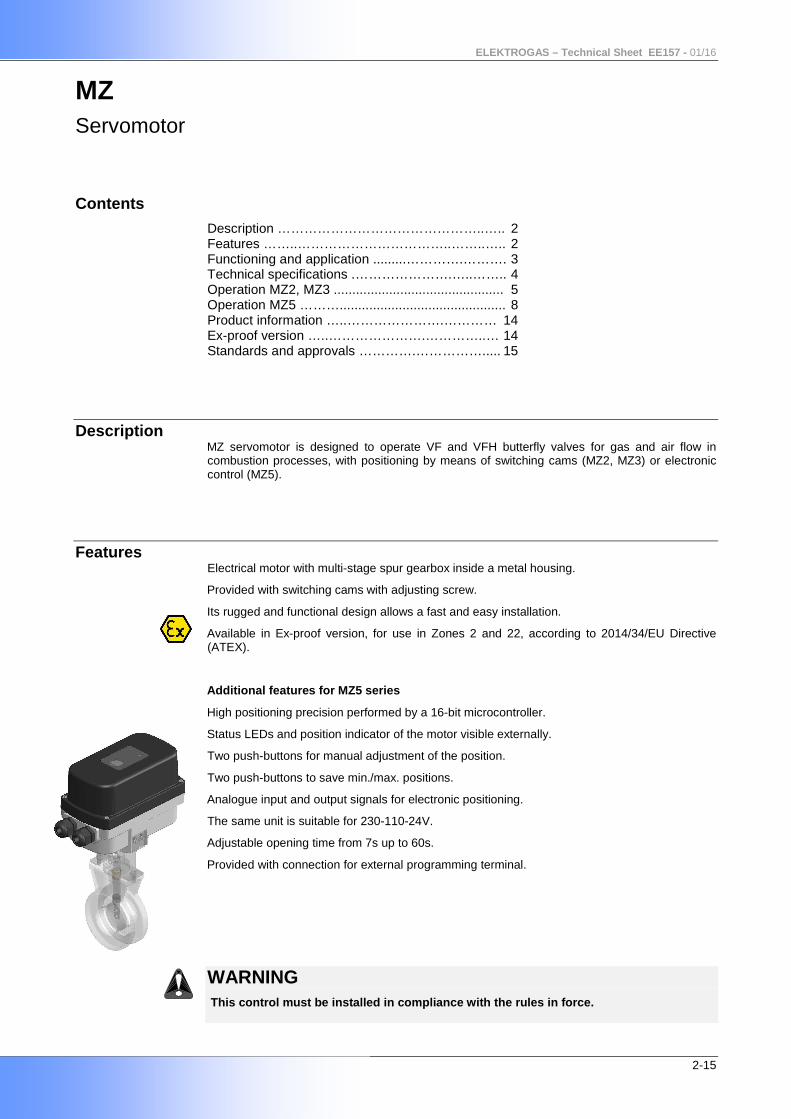
Features Electrical motor with multi-stage spur gearbox inside a metal housing.
Provided with switching cams with adjusting screw.
Its rugged and functional design allows a fast and easy installation.
Available in Ex-proof version, for use in Zones 2 and 22, according to 2014/34/EU Directive (ATEX).
Additional features for MZ5 series
High positioning precision performed by a 16-bit microcontroller.
Status LEDs and position indicator of the motor visible externally.
Two push-buttons for manual adjustment of the position.
Two push-buttons to save min./max. positions.
Analogue input and output signals for electronic positioning.
The same unit is suitable for 230-110-24V.
Adjustable opening time from 7s up to 60s.
Provided with connection for external programming terminal.
WARNING This control must be installed in compliance with the rules in force.
ELEKTROGAS – Technical Sheet EE157 - 01/16
3-15
Functioning and
application
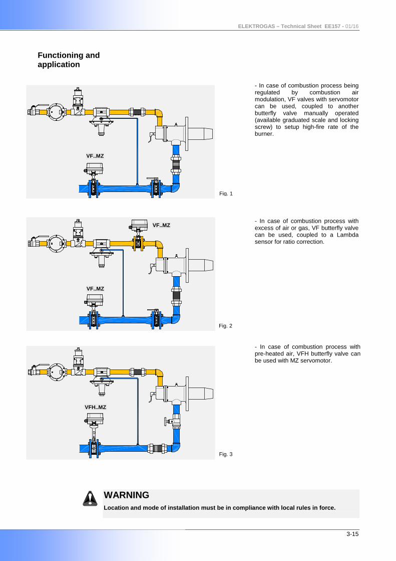
- In case of combustion process being regulated by combustion air modulation, VF valves with servomotor can be used, coupled to another butterfly valve manually operated (available graduated scale and locking screw) to setup high-fire rate of the burner.
- In case of combustion process with excess of air or gas, VF butterfly valve can be used, coupled to a Lambda sensor for ratio correction.
- In case of combustion process with
pre-heated air, VFH butterfly valve can be used with MZ servomotor.
WARNING Location and mode of installation must be in compli ance with local rules in force.
VF..MZ
Fig. 1
Fig. 2
Fig. 3
VF..MZ
VFH..MZ
VF..MZ
ELEKTROGAS – Technical Sheet EE157 - 01/16
4-15
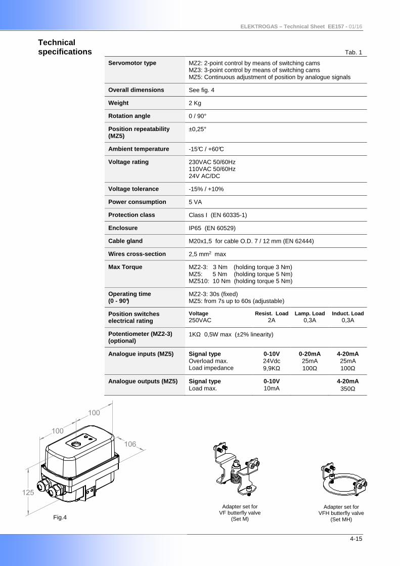
Technical specifications Tab. 1
Servomotor type MZ2: 2-point control by means of switching cams MZ3: 3-point control by means of switching cams MZ5: Continuous adjustment of position by analogue signals
Overall dimensions See fig. 4
Weight 2 Kg
Rotation a ngle 0 / 90°
Position repeatability (MZ5)
±0,25°
Ambient temperature -15°C / +60°C
Voltage rating 230VAC 50/60Hz 110VAC 50/60Hz 24V AC/DC
Voltage tolerance -15% / +10%
Power consumption 5 VA
Protection class Class I (EN 60335-1)
Enclosure IP65 (EN 60529)
Cable gland M20x1,5 for cable O.D. 7 / 12 mm (EN 62444)
Wires cross -section 2,5 mm2 max
Max Torque
MZ2-3: 3 Nm (holding torque 3 Nm) MZ5: 5 Nm (holding torque 5 Nm) MZ510: 10 Nm (holding torque 5 Nm)
Operating time (0 - 90°)
MZ2-3: 30s (fixed) MZ5: from 7s up to 60s (adjustable)
Position switches electrical rating
Voltage 250VAC
Resist. Load 2A
Lamp. Load 0,3A
Induct. Load 0,3A
Potentiometer (MZ2 -3) (optional)
1KΩ 0,5W max (±2% linearity)
Analogue inputs (MZ5) Signal typ e Overload max. Load impedance
0-10V 24Vdc 9,9KΩ
0-20mA 25mA 100Ω
4-20mA 25mA 100Ω
Analogue outputs (MZ5) Signal type Load max.
0-10V 10mA
4-20mA 350Ω
Fig.4
Adapter set for VF butterfly valve
(Set M)
Adapter set for VFH butterfly valve
(Set MH)
ELEKTROGAS – Technical Sheet EE157 - 01/16
5-15
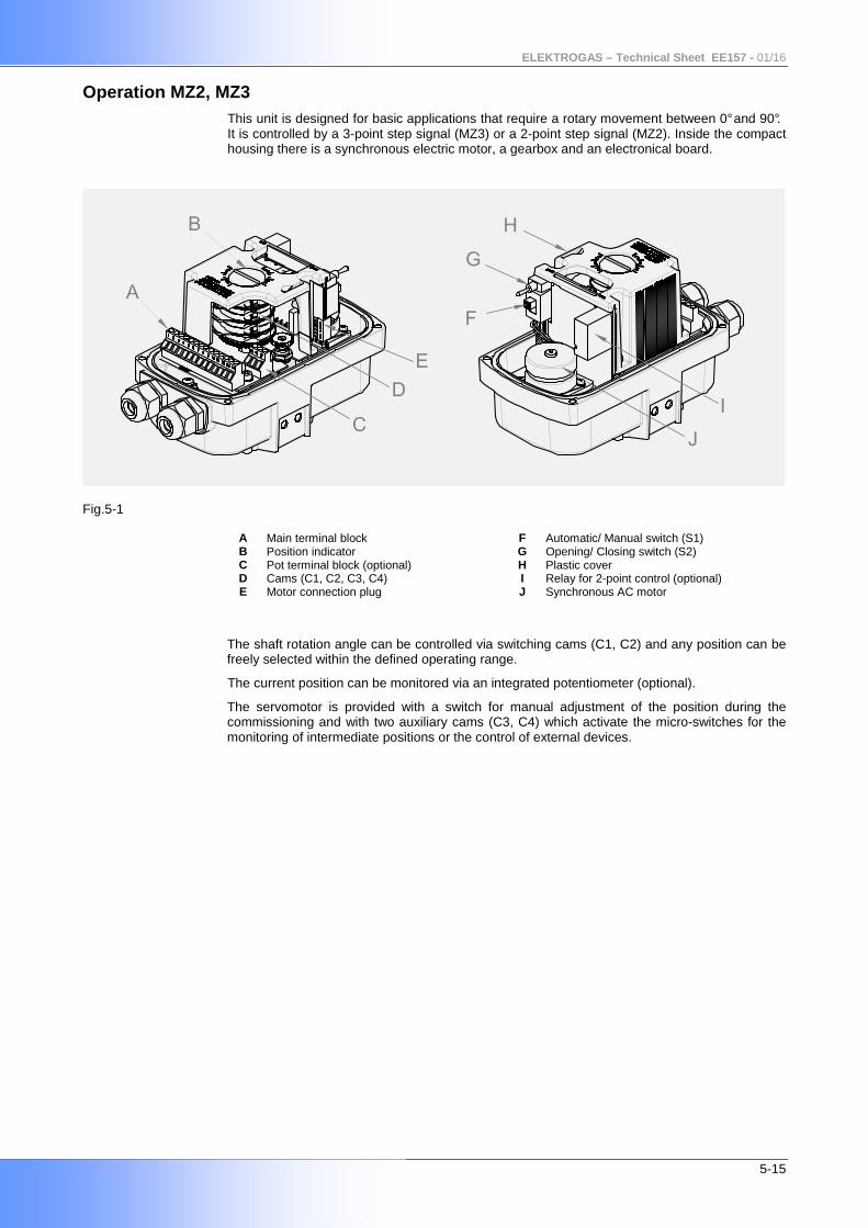
Operation MZ2, MZ3 This unit is designed for basic applications that require a rotary movement between 0° and 90°. It is controlled by a 3-point step signal (MZ3) or a 2-point step signal (MZ2). Inside the compact housing there is a synchronous electric motor, a gearbox and an electronical board.
Fig.5-1
A Main terminal block F Automatic/ Manual switch (S1) B Position indicator G Opening/ Closing switch (S2) C Pot terminal block (optional) H Plastic cover D Cams (C1, C2, C3, C4) I Relay for 2-point control (optional) E Motor connection plug J Synchronous AC motor
The shaft rotation angle can be controlled via switching cams (C1, C2) and any position can be freely selected within the defined operating range.
The current position can be monitored via an integrated potentiometer (optional).
The servomotor is provided with a switch for manual adjustment of the position during the commissioning and with two auxiliary cams (C3, C4) which activate the micro-switches for the monitoring of intermediate positions or the control of external devices.
ELEKTROGAS – Technical Sheet EE157 - 01/16
6-15
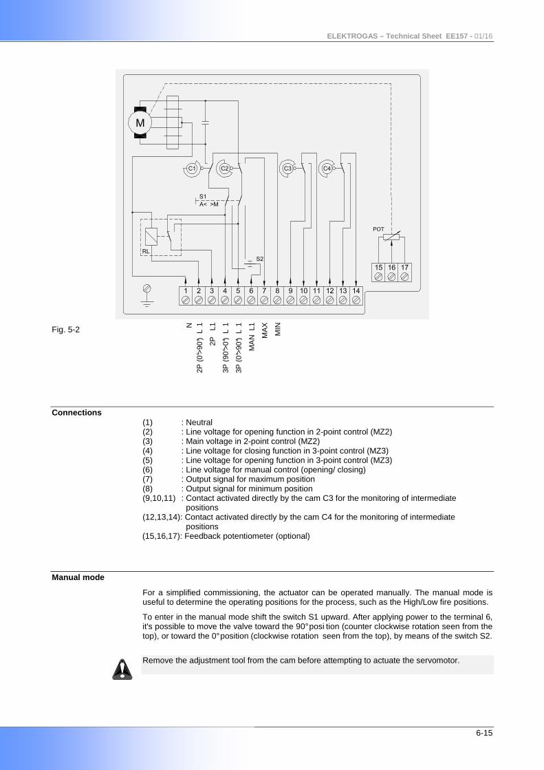
Fig. 5-2
Connections
(1) : Neutral (2) : Line voltage for opening function in 2-point control (MZ2) (3) : Main voltage in 2-point control (MZ2) (4) : Line voltage for closing function in 3-point control (MZ3) (5) : Line voltage for opening function in 3-point control (MZ3) (6) : Line voltage for manual control (opening/ closing) (7) : Output signal for maximum position (8) : Output signal for minimum position (9,10,11) : Contact activated directly by the cam C3 for the monitoring of intermediate positions (12,13,14): Contact activated directly by the cam C4 for the monitoring of intermediate positions
(15,16,17): Feedback potentiometer (optional)
Manual mode
For a simplified commissioning, the actuator can be operated manually. The manual mode is useful to determine the operating positions for the process, such as the High/Low fire positions.
To enter in the manual mode shift the switch S1 upward. After applying power to the terminal 6, it's possible to move the valve toward the 90° posi tion (counter clockwise rotation seen from the top), or toward the 0° position (clockwise rotation seen from the top), by means of the switch S2.
Remove the adjustment tool from the cam before attempting to actuate the servomotor.
N
2P (
0°>
90°)
L1
2P
L1
3P (
90°>
0°)
L1
3P (
0°>
90°)
L1
MA
N L
1
MA
X
MIN
ELEKTROGAS – Technical Sheet EE157 - 01/16
7-15
Setting of the MIN and MAX positions From factory the minimum position is set up to 0° a nd the maximum is set up to 90°. Different positions can be adjusted by means of the cams C1 and C2. Do not exceed the limits 0°-90° when the potentiome ter is installed.
Automatic mode
To enter in the automatic mode shift the switch S1 downward.
2-point control (MZ2)
Apply permanent power to the terminal 3. It's possible to move the valve toward the 90° position (counter clockwise rotation seen from the top), applying line voltage to the terminal 2. The rotation stops when the maximum position is reached (cam C2).
If the voltage to the terminal 2 is disconnected the servo moves toward the 0° position (clockwise rotation seen from the top). The rotation stops when the minimum position is reached (cam C1).
3-point control (MZ3)
It's possible to move the valve toward the 90° posi tion (counter clockwise rotation seen from the top), applying line voltage to the terminal 5. The rotation stops when the maximum position is reached (cam C2 switches the line voltage to the terminal 7) or when the voltage to the terminal 5 is disconnected.
It's possible to move the valve toward the 0° posit ion (clockwise rotation seen from the top), applying line voltage to the terminal 4. The rotation stops when the minimum position is reached (cam C1 switches the line voltage to the terminal 8) or when the voltage to the terminal 4 is disconnected.
Potentiometer
A feedback potentiometer can be fitted to monitor the current position of the servomotor. The change in position of the actuator is transmitted to the potentiometer wiper by means of a gear set and can be measured as a changing voltage. It must be connected as a voltage divider with an high impedance load. The potentiometer cannot be retrofitted, but it must be factory installed as optional.
ELEKTROGAS – Technical Sheet EE157 - 01/16
8-15
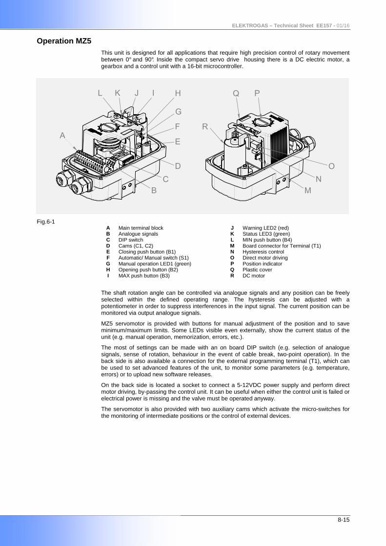
Operation MZ5 This unit is designed for all applications that require high precision control of rotary movement between 0° and 90°. Inside the compact servo drive housing there is a DC electric motor, a gearbox and a control unit with a 16-bit microcontroller.
Fig.6-1
A Main terminal block J Warning LED2 (red) B Analogue signals K Status LED3 (green) C DIP switch L MIN push button (B4) D Cams (C1, C2) M Board connector for Terminal (T1) E Closing push button (B1) N Hysteresis control F Automatic/ Manual switch (S1) O Direct motor driving G Manual operation LED1 (green) P Position indicator H Opening push button (B2) Q Plastic cover I MAX push button (B3) R DC motor
The shaft rotation angle can be controlled via analogue signals and any position can be freely selected within the defined operating range. The hysteresis can be adjusted with a potentiometer in order to suppress interferences in the input signal. The current position can be monitored via output analogue signals.
MZ5 servomotor is provided with buttons for manual adjustment of the position and to save minimum/maximum limits. Some LEDs visible even externally, show the current status of the unit (e.g. manual operation, memorization, errors, etc.).
The most of settings can be made with an on board DIP switch (e.g. selection of analogue signals, sense of rotation, behaviour in the event of cable break, two-point operation). In the back side is also available a connection for the external programming terminal (T1), which can be used to set advanced features of the unit, to monitor some parameters (e.g. temperature, errors) or to upload new software releases.
On the back side is located a socket to connect a 5-12VDC power supply and perform direct motor driving, by-passing the control unit. It can be useful when either the control unit is failed or electrical power is missing and the valve must be operated anyway.
The servomotor is also provided with two auxiliary cams which activate the micro-switches for the monitoring of intermediate positions or the control of external devices.
ELEKTROGAS – Technical Sheet EE157 - 01/16
9-15
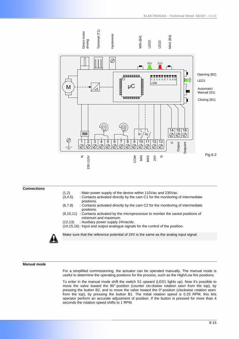
Fig.6-2
Connections
(1,2) : Main power supply of the device within 110Vac and 230Vac. (3,4,5) : Contacts activated directly by the cam C1 for the monitoring of intermediate positions. (6,7,8) : Contacts activated directly by the cam C2 for the monitoring of intermediate positions. (9,10,11) : Contacts activated by the microprocessor to monitor the saved positions of minimum and maximum. (12,13) : Auxiliary power supply 24Vac/dc. (14,15,16) : Input and output analogue signals for the control of the position. Make sure that the reference potential of 24V is the same as the analog input signal.
Manual mode
For a simplified commissioning, the actuator can be operated manually. The manual mode is useful to determine the operating positions for the process, such as the High/Low fire positions.
To enter in the manual mode shift the switch S1 upward (LED1 lights up). Now it's possible to move the valve toward the 90° position (counter clo ckwise rotation seen from the top), by pressing the button B2, and to move the valve toward the 0° position (clockwise rotation seen from the top), by pressing the button B1. The initial rotation speed is 0.25 RPM, this lets operator perform an accurate adjustment of position. If the button is pressed for more than 4 seconds the rotation speed shifts to 1 RPM.
Opening (B2)
Automatic/ Manual (S1)
Closing (B1)
Set
poin
t
Out
put0
N
230-
110V
CO
M
MIN
MA
X
24V
N
Dire
ct m
otor
dr
ivin
g
Ter
min
al (
T1)
Hys
tere
sis
MIN
(B
4)
MA
X (
B3)
LED1
LED
3
LED
2
ELEKTROGAS – Technical Sheet EE157 - 01/16
10-15
Setting of the MIN and MAX positions In manual mode it's possible to save current position as MIN (MAX) by pressing button B4 (B3) for more than 3 seconds (shorter pressing are not considered). When the position is saved, LED3 lights up permanently and the button may be released. MAX position can not be lower than MIN saved position (and vice versa). In this case the position won't be saved and an alarm will go up (see "Alarms Chart") until a new proper position is saved. Running time setting (continuous) Factory standard setting for running time is 30s for 0-90°. However, requested running time is setup in the factory prior despatch according to customer’s order information. In case of need, it can be modified on the field by the user by means of terminal T1 (optional) or in manual mode, according to following instructions. Press both B3 and B4 buttons at the same time, keeping the buttons pressed for the time required (LED3 lights up). Running time must be included between 7 s and 60 s, otherwise its value will not be saved and an alarm will go up (see "Alarms Chart") until a new proper time is saved. The adjusted running time will become operative as the user switches from manual mode back to automatic mode.
Automatic mode
In the automatic mode the angular position corresponds to the input analogue signal supplied by a setpoint device. Factory setting allows full range of operation (0-90°) but, as above described, MIN and MAX position can be set within this range in manual mode.
An output analogue signal proportional to angular position is also provided.
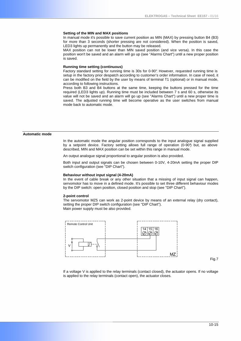
Both input and output signals can be chosen between 0-10V, 4-20mA setting the proper DIP switch configuration (see "DIP Chart"). Behaviour without input signal (4-20mA) In the event of cable break or any other situation that a missing of input signal can happen, servomotor has to move in a defined mode. It's possible to set three different behaviour modes by the DIP switch: open position, closed position and stop (see "DIP Chart"). 2-point control The servomotor MZ5 can work as 2-point device by means of an external relay (dry contact), setting the proper DIP switch configuration (see "DIP Chart"). Main power supply must be also provided.
Fig.7 If a voltage V is applied to the relay terminals (contact closed), the actuator opens. If no voltage is applied to the relay terminals (contact open), the actuator closes.
Remote Control Unit
ELEKTROGAS – Technical Sheet EE157 - 01/16
11-15
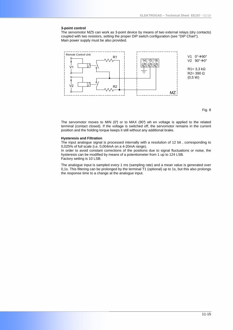
3-point control The servomotor MZ5 can work as 3-point device by means of two external relays (dry contacts) coupled with two resistors, setting the proper DIP switch configuration (see "DIP Chart"). Main power supply must be also provided. V1 0°90° V2 90°0° R1= 3,3 kΩ R2= 390 Ω (0,5 W)
Fig. 8 The servomotor moves to MIN (0°) or to MAX (90°) wh en voltage is applied to the related terminal (contact closed). If the voltage is switched off, the servomotor remains in the current position and the holding torque keeps it still without any additional brake. Hysteresis and Filtration The input analogue signal is processed internally with a resolution of 12 bit , corresponding to 0,025% of full scale (i.e. 0,004mA on a 4-20mA range). In order to avoid constant corrections of the positions due to signal fluctuations or noise, the hysteresis can be modified by means of a potentiometer from 1 up to 124 LSB. Factory setting is 10 LSB.
The analogue input is sampled every 1 ms (sampling rate) and a mean value is generated over 0,1s. This filtering can be prolonged by the terminal T1 (optional) up to 1s, but this also prolongs the response time to a change at the analogue input.
Remote Control Unit
ELEKTROGAS – Technical Sheet EE157 - 01/16
12-15
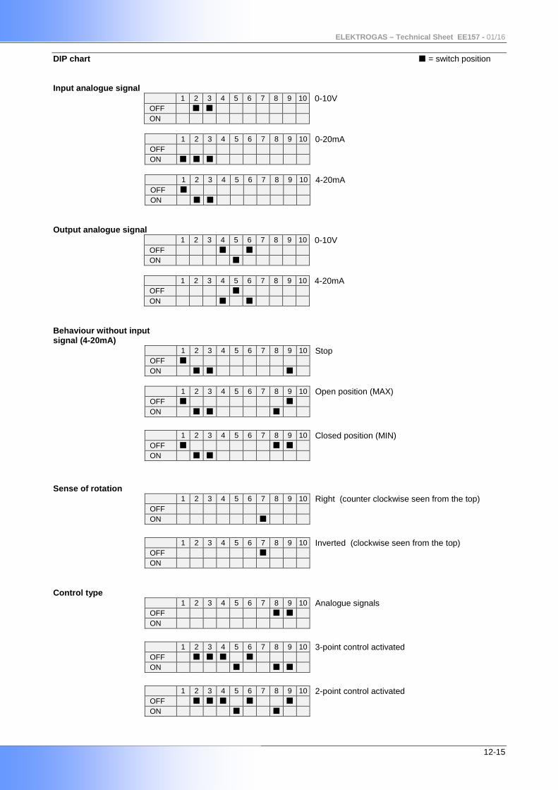
DIP chart = switch position Input analogue signal
1 2 3 4 5 6 7 8 9 10 0-10V OFF ON
1 2 3 4 5 6 7 8 9 10 0-20mA
OFF ON
1 2 3 4 5 6 7 8 9 10 4-20mA
OFF ON
Output analogue signal
1 2 3 4 5 6 7 8 9 10 0-10V OFF ON
1 2 3 4 5 6 7 8 9 10 4-20mA
OFF ON
Behaviour without input signal (4-20mA)
1 2 3 4 5 6 7 8 9 10 Stop OFF ON
1 2 3 4 5 6 7 8 9 10 Open position (MAX)
OFF ON
1 2 3 4 5 6 7 8 9 10 Closed position (MIN)
OFF ON
Sense of rotation
1 2 3 4 5 6 7 8 9 10 Right (counter clockwise seen from the top) OFF ON
1 2 3 4 5 6 7 8 9 10 Inverted (clockwise seen from the top)
OFF ON
Control type
1 2 3 4 5 6 7 8 9 10 Analogue signals OFF
ON
1 2 3 4 5 6 7 8 9 10 3-point control activated
OFF ON
1 2 3 4 5 6 7 8 9 10 2-point control activated
OFF ON
ELEKTROGAS – Technical Sheet EE157 - 01/16
13-15
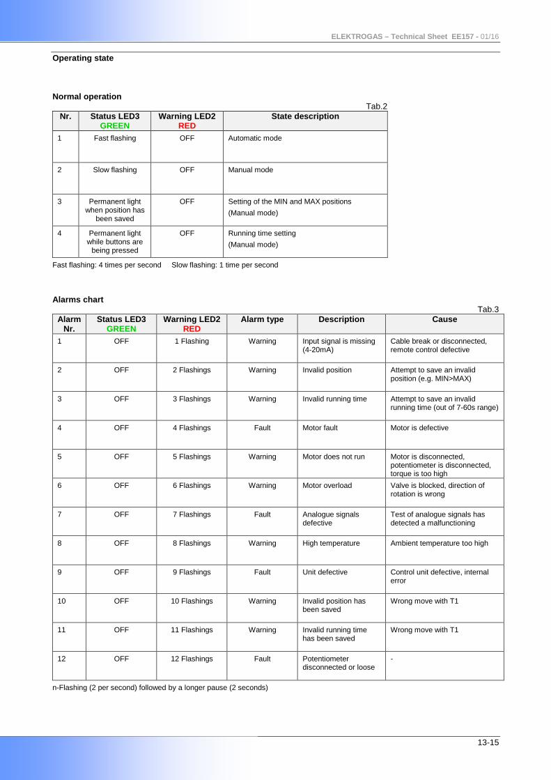
Operating state Normal operation Tab.2
Nr. Status LED3 GREEN
Warning LED2 RED
State description
1
Fast flashing OFF Automatic mode
2
Slow flashing OFF Manual mode
3
Permanent light when position has
been saved
OFF Setting of the MIN and MAX positions
(Manual mode)
4 Permanent light while buttons are
being pressed
OFF Running time setting
(Manual mode)
Fast flashing: 4 times per second Slow flashing: 1 time per second
Alarms chart
Tab.3 Alarm
Nr. Status LED3
GREEN Warning LED2
RED Alarm type Description Cause
1 OFF 1 Flashing Warning Input signal is missing (4-20mA)
Cable break or disconnected, remote control defective
2 OFF 2 Flashings Warning Invalid position Attempt to save an invalid position (e.g. MIN>MAX)
3 OFF 3 Flashings Warning Invalid running time Attempt to save an invalid running time (out of 7-60s range)
4 OFF 4 Flashings Fault Motor fault
Motor is defective
5 OFF
5 Flashings
Warning Motor does not run Motor is disconnected, potentiometer is disconnected, torque is too high
6 OFF
6 Flashings
Warning Motor overload Valve is blocked, direction of rotation is wrong
7 OFF
7 Flashings
Fault Analogue signals defective
Test of analogue signals has detected a malfunctioning
8 OFF
8 Flashings
Warning High temperature Ambient temperature too high
9 OFF
9 Flashings
Fault Unit defective Control unit defective, internal error
10 OFF
10 Flashings
Warning Invalid position has been saved
Wrong move with T1
11 OFF
11 Flashings
Warning Invalid running time has been saved
Wrong move with T1
12 OFF
12 Flashings
Fault Potentiometer disconnected or loose
-
n-Flashing (2 per second) followed by a longer pause (2 seconds)
ELEKTROGAS – Technical Sheet EE157 - 01/16
14-15
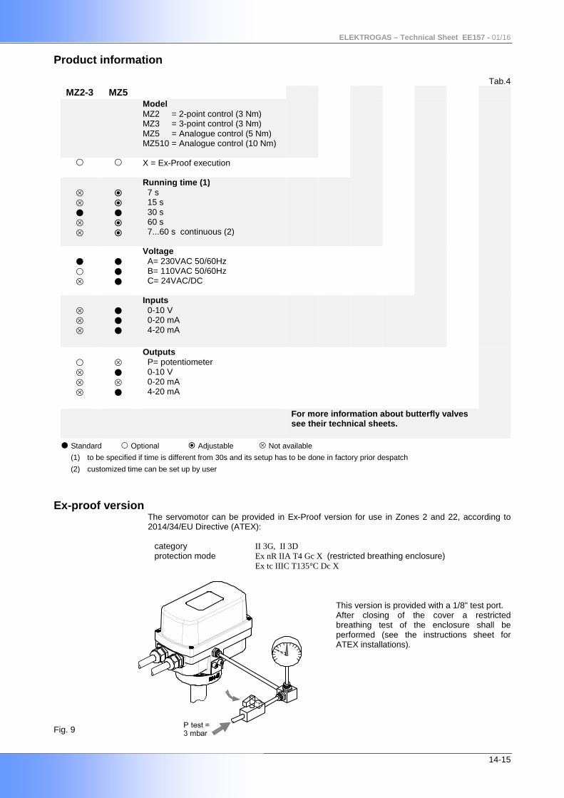
Product information
Tab.4 MZ2-3 MZ5
Model MZ2 = 2-point control (3 Nm) MZ3 = 3-point control (3 Nm) MZ5 = Analogue control (5 Nm) MZ510 = Analogue control (10 Nm)
X = Ex-Proof execution
Running time (1) 7 s 15 s 30 s 60 s 7...60 s continuous (2)
Voltage A= 230VAC 50/60Hz B= 110VAC 50/60Hz C= 24VAC/DC
Inputs 0-10 V 0-20 mA 4-20 mA
Outputs P= potentiometer 0-10 V 0-20 mA 4-20 mA
For more information about butterfly valves see their technical sheets.
Standard Optional Adjustable Not available (1) to be specified if time is different from 30s and its setup has to be done in factory prior despatch
(2) customized time can be set up by user
Ex-proof version The servomotor can be provided in Ex-Proof version for use in Zones 2 and 22, according to 2014/34/EU Directive (ATEX):
category II 3G, II 3D protection mode Ex nR IIA T4 Gc X (restricted breathing enclosure) Ex tc IIIC T135°C Dc X This version is provided with a 1/8" test port. After closing of the cover a restricted breathing test of the enclosure shall be performed (see the instructions sheet for ATEX installations). Fig. 9
ELEKTROGAS – Technical Sheet EE157 - 01/16
15-15
Standards and approvals The product complies with the essential requirements of the following European Directives and
their amendments: 2009/142/EC (Gas Appliances Directive) Reg.-No 01MECH
2014/34/EU (ATEX) when shown upon the product 2014/30/EU (Electromagnetic Compatibility) 2014/35/EU (Low Voltage Directive)
2011/65/EU (RoHS II)
The product complies with the Technical Regulation TP TC 004/2011-016/2011-020/2011-
032/2013 of Russia, Belarus and Kazakhstan. Certificate No.: TC RU Д-IT.PA01.B.21942
Quality Management System is certified according to UNI EN ISO 9001.
The information in this document contains general descriptions of technical options available and based on current specifications. The company reserves the right to make changes in specifications and models as design improvements are introduced, without prior notice.
Elektrogas is a brand name of: Elettromeccanica Delta S.p.A. Via Trieste 132 31030 Arcade (TV) – ITALY tel +39 0422 874068 fax +39 0422 874048 www.delta-elektrogas.com [email protected] Copyright © 2016 All rights reserved


![Especiais 05 Servomotor [Modo de Compatibilidade]](https://img.pdfslide.tips/doc/110x75/616a16e911a7b741a34eb052/especiais-05-servomotor-modo-de-compatibilidade.jpg)
