Embed Size (px)
Citation preview
MZB1001T02
1 April.2014
Low-profile, high-speed and high-pressure air pump
1. Feature
High speed & high pressure air blowing
Less pulsation air flow
Quick response
Small size : 20 x 20 mm, t=1.85mm (nozzle height : 1.6mm)
Weight : 1.4±0.2 g
2. Application
Air pump application
Spot air blowing application
Liquid sending at high pressure air
Air sucking , blowing , circulation application
3. Part Number Configuration
MZ B1 001 T02
① ② ③ ④
① Product ID
② Series (B : blower)
③ Representative characteristic
④ Packaging (T : tray)
Note:
This catalog is for reference only and not an official product specification document, therefore, please review and approve our official product specification before ordering this product.
MZB1001T02
2 April.2014
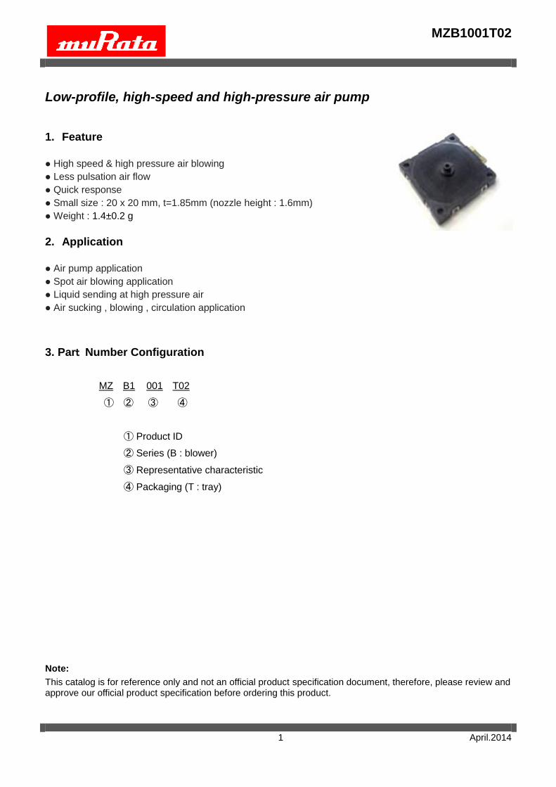
4. Dimensions & Marking (Unit: mm)
Item Specification Condition
Outside dimension/tolerance 20±0.15mm
thickness tolerance 1.85±0.2mm except the nozzle
Nozzle height/tolerance 1.60±0.15mm from top of the nozzle to top plate
Upper Line:Product name
Middle Line:Year & Week
(Example)
MZB1001T02
3 April.2014
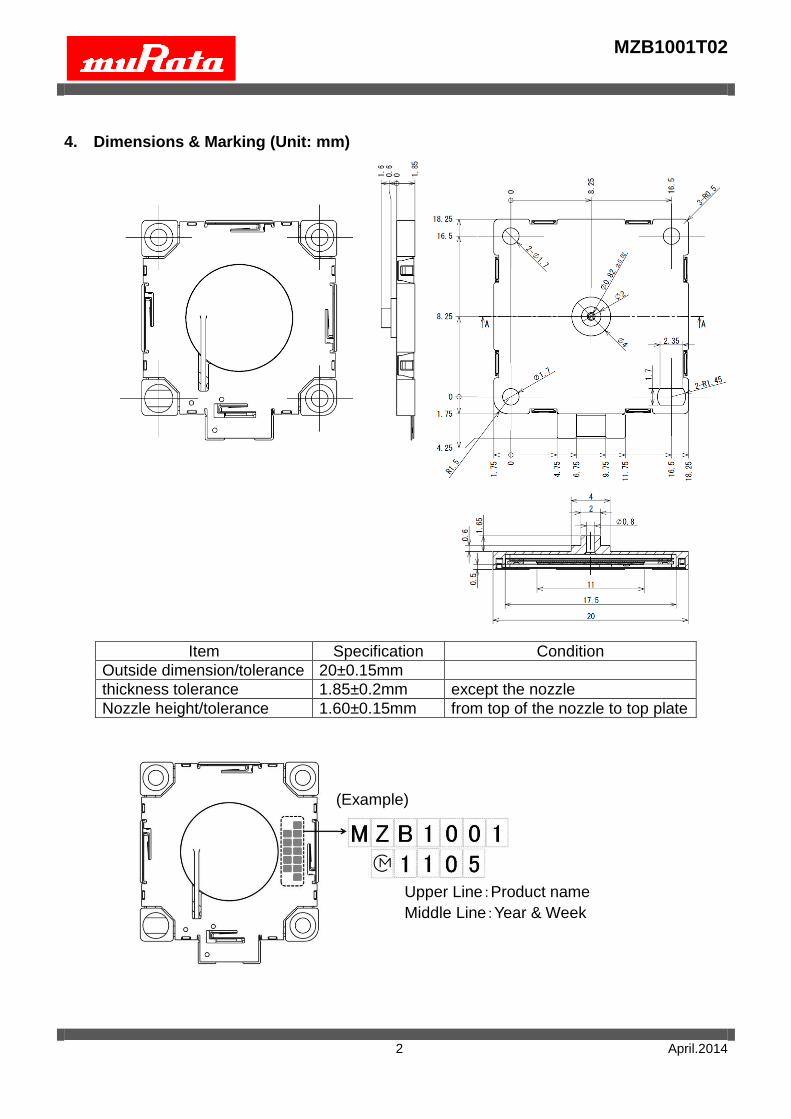
5. Maximum Ratings
Rating Value Unit
Operating Sinusoidal Voltage Range 10 to 20 Vp-p
Absolute maximum rating voltage 30 Vp-p
Operating Temperature Range 0 to +70 °C
6. Electrical Characteristics
Parameter Specification Units Conditions
Resonant Frequency 24.0 to 27.0 kHz Section 7
Flow Rate ≧0.70 L/min. Section 7 Back pressure: 0.05kPa
Static Pressure ≧1.42 kPa Section 7
Temperature Characteristics
Flow Rate
(from initial value)
±20% (Typ) - Section 7
7. Measuring method
(Measuring Condition)
Driving voltage: 15Vp-p Unless otherwise specified, the standard range of atmospheric conditions for making measurements and tests is as follows:
Ambient temperature : 15 °C to 35°C
Relative humidity : 25% to 85%
If there is any doubt about the results, measurement shall be made within the following limits:
Ambient temperature : 25 ± 1 °C
Relative humidity : 63% to 67%
MZB1001T02
4 April.2014
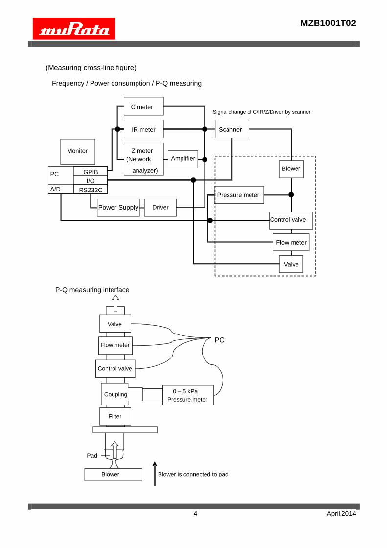
(Measuring cross-line figure)
Frequency / Power consumption / P-Q measuring
P-Q measuring interface
Pressure meter
Pad
Coupling
Filter
Blower is connected to pad Blower
PC
Control valve
Flow meter
Valve
0 – 5 kPa
Scanner
Blower
Power Supply
Monitor
PC GPIB
RS232C
I/O
Flow meter
Pressure meter A/D
C meter
IR meter
Z meter
(Network
analyzer)
Driver
Amplifier
Valve
Control valve
Signal change of C/IR/Z/Driver by scanner
MZB1001T02
5 April.2014
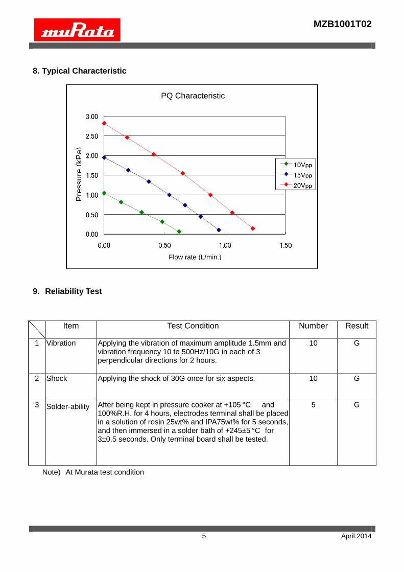
8. Typical Characteristic
9. Reliability Test
Note) At Murata test condition
Item Test Condition Number Result
1 Vibration Applying the vibration of maximum amplitude 1.5mm and vibration frequency 10 to 500Hz/10G in each of 3 perpendicular directions for 2 hours.
10 G
2 Shock Applying the shock of 30G once for six aspects. 10 G
3 Solder-ability After being kept in pressure cooker at +105 °C and 100%R.H. for 4 hours, electrodes terminal shall be placed in a solution of rosin 25wt% and IPA75wt% for 5 seconds, and then immersed in a solder bath of +245±5 °C for 3±0.5 seconds. Only terminal board shall be tested.
5 G
PQ Characteristic
Flow rate (L/min.)
Pre
ssu
re (
kP
a)
MZB1001T02
6 April.2014
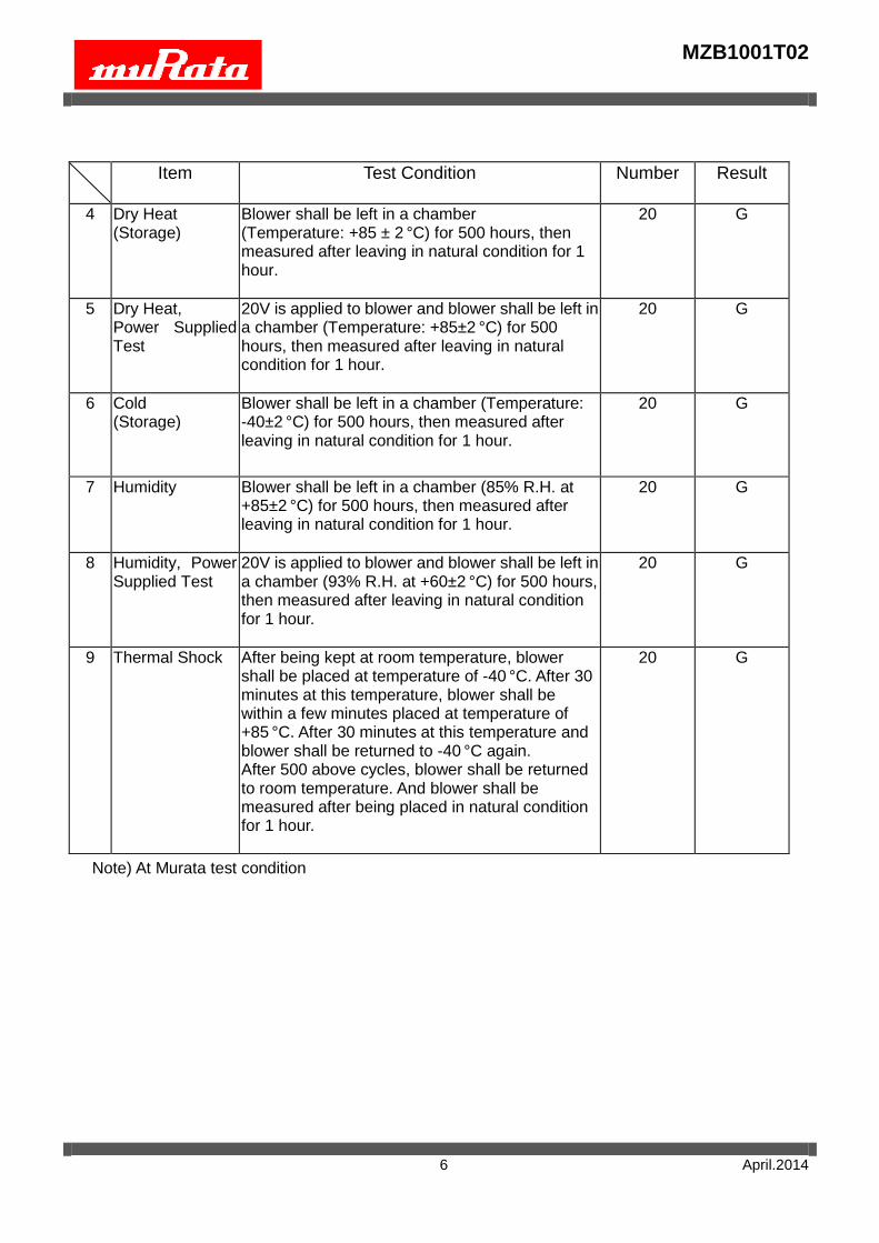
Item Test Condition
Number Result
4 Dry Heat (Storage)
Blower shall be left in a chamber (Temperature: +85 ± 2 °C) for 500 hours, then measured after leaving in natural condition for 1 hour.
20 G
5 Dry Heat, Power Supplied Test
20V is applied to blower and blower shall be left in a chamber (Temperature: +85±2 °C) for 500 hours, then measured after leaving in natural condition for 1 hour.
20 G
6 Cold (Storage)
Blower shall be left in a chamber (Temperature: -40±2 °C) for 500 hours, then measured after leaving in natural condition for 1 hour.
20 G
7 Humidity Blower shall be left in a chamber (85% R.H. at +85±2 °C) for 500 hours, then measured after leaving in natural condition for 1 hour.
20 G
8 Humidity, Power Supplied Test
20V is applied to blower and blower shall be left in a chamber (93% R.H. at +60±2 °C) for 500 hours, then measured after leaving in natural condition for 1 hour.
20 G
9 Thermal Shock After being kept at room temperature, blower shall be placed at temperature of -40 °C. After 30 minutes at this temperature, blower shall be within a few minutes placed at temperature of +85 °C. After 30 minutes at this temperature and blower shall be returned to -40 °C again. After 500 above cycles, blower shall be returned to room temperature. And blower shall be measured after being placed in natural condition for 1 hour.
20 G
Note) At Murata test condition
MZB1001T02
7 April.2014
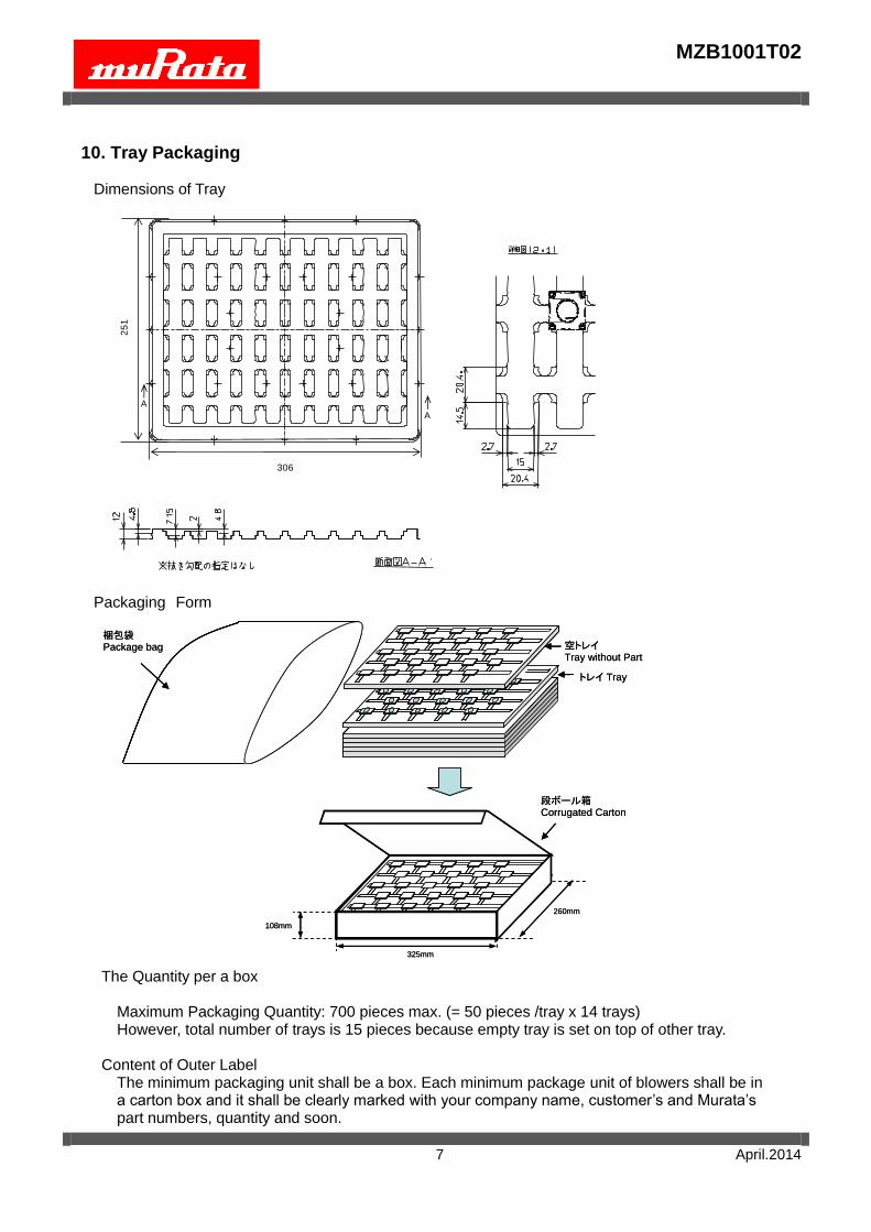
10. Tray Packaging
Dimensions of Tray
Packaging Form
The Quantity per a box
Maximum Packaging Quantity: 700 pieces max. (= 50 pieces /tray x 14 trays) However, total number of trays is 15 pieces because empty tray is set on top of other tray.
Content of Outer Label
The minimum packaging unit shall be a box. Each minimum package unit of blowers shall be in a carton box and it shall be clearly marked with your company name, customer’s and Murata’s part numbers, quantity and soon.
25
1
306
A
A
段ボール箱Corrugated Carton
260mm
325mm
108mm
梱包袋Package bag 空トレイ
Tray without Part
トレイ Tray
段ボール箱Corrugated Carton
260mm
325mm
108mm
梱包袋Package bag 空トレイ
Tray without Part
トレイ Tray
MZB1001T02
8 April.2014
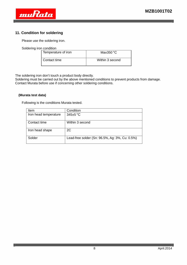
11. Condition for soldering
Please use the soldering iron.
Soldering iron condition
Temperature of iron
Max350 °C
Contact time
Within 3 second
The soldering iron don’t touch a product body directly. Soldering must be carried out by the above mentioned conditions to prevent products from damage. Contact Murata before use if concerning other soldering conditions.
(Murata test data)
Following is the conditions Murata tested.
Item Condition
Iron head temperature 345±5 °C
Contact time Within 3 second
Iron head shape 2C
Solder Lead-free solder (Sn: 96.5%, Ag: 3%, Cu: 0.5%)
MZB1001T02
9 April.2014
NOTICE
1. Storage Conditions:
To avoid damaging the performance and solderability, be sure to observe the following points. - Store the products in room where the temperature / humidity is stable.
And avoid such places where there are large temperature changes. Please store the products under the following conditions :
Temperature : -10 to +40 ℃ Humidity : 10 to 85% R.H.
- Expire date (Shelf life) of the products is 6 months after delivery under the conditions of a sealed and an unopened package. Please use the products within 6 months after delivery. If you store the products for a long time (more than 6months), use carefully because the products may be degraded in the solder-ability and/or rusty. Please confirm solder-ability and characteristics for the products regularly.
- Please do not store the products in a chemical atmosphere (Acids, Alkali, Bases, Organic gas, Sulfides and so on), because the characteristics may be reduced in quality, and/or be degraded in the solder-ability due to the storage in a chemical atmosphere.
- Please do not put the products directly on the floor without anything under them to avoid damp places and/or dusty places.
- Please do not store the products in the places such as : in a damp heated place, in a place where direct sunlight comes in, in place applying vibrations.
- Please use the products immediately after the package is opened, because the characteristics
may be reduced in quality, and/or be degraded in the solder-ability due to storage under the poor condition.
- Please do not drop the products to avoid cracking of ceramic element.
2. Handling Conditions:
- Be careful in handling or transporting products because excessive stress or mechanical shock may break products.
- Please do not touch the component (included nozzle, wiring etc.) with bare hands. Please set bottom plate on the downside.
- Please do not touch a wiring to the piezoelectric ceramic of the component inside.
- Applying load on the central area of the product may cause crack in the ceramic element.
- Please handle only edge. Don’t hold nozzle directly and stress to nozzle.
- The component may be damaged if mechanical stress over this specification is applied to the part’s body and nozzle.
MZB1001T02
10 April.2014
- Please pay attention to protect operating circuit from surge voltage provided by something of force such as falling, shock and temperature changing.
- Please pay attention never to apply DC voltage to the product.
- Washing of the component is not acceptable, because it is not sealed.
- Micro blower is sensitive to dirty environments. It brings out best performance and longevity in sealed environments.
- The smoke of tobacco, mosquito-repellant incense etc. may influence a product life
- Please contact us when the component is screwed on body of equipment or fixed with double-side tape.
3. Cleaning Conditions:
Any cleaning is not permitted. 4. Operational Environment Conditions:
Products are designed to work for electronic products under normal environmental conditions
(ambient temperature, humidity and pressure). Therefore, products have no problems to be used
under the similar conditions to the above-mentioned. However, if products are used under the
following circumstances, it may damage products and leakage of electricity and abnormal temperature
may occur.
- In an atmosphere containing corrosive gas ( Cl2, NH3, SOx, NOx etc.).
- In an atmosphere containing combustible and volatile gases.
- In a dusty environment. - Direct sunlight
- Water splashing place.
- Humid place where water condenses.
- In a freezing environment.
If there are possibilities for products to be used under the preceding clause, consult with Murata before
actual use.
If product malfunctions may result in serious damage, including that to human life, sufficient fail-safe
measures must be taken, including the following:
(1) Installation of protection circuits or other protective device to improve system safety
(2) Installation of redundant circuits in the case of single-circuit failure
MZB1001T02
11 April.2014
5. Limitation of Applications:
The products are designed and produced for application in ordinary electronic equipment (AV equipment, OA equipment, telecommunication, etc). If the products are to be used in devices requiring extremely high reliability following the application listed below, you should consult with the Murata staff in advance. - Aircraft equipment. - Aerospace equipment - Undersea equipment. - Power plant control equipment. - Medical equipment. - Transportation equipment (vehicles, trains, ships, etc.). - Traffic signal equipment. - Disaster prevention / crime prevention equipment. - Data-procession equipment. - Application which malfunction or operational error may endanger human life and property of assets. - Application which related to occurrence the serious damage - Application of similar complexity and/ or reliability requirements to the applications listed in the above.
! Note: Please make sure that your product has been evaluated and confirmed against your specifications
when our product is mounted to your product.
Product specifications are subject to change or our products in it may be discontinued without advance
notice.
This catalog is for reference only and not an official product specification document, therefore, please
review and approve our official product specification before ordering this product.
MZB1001T02
12 April.2014
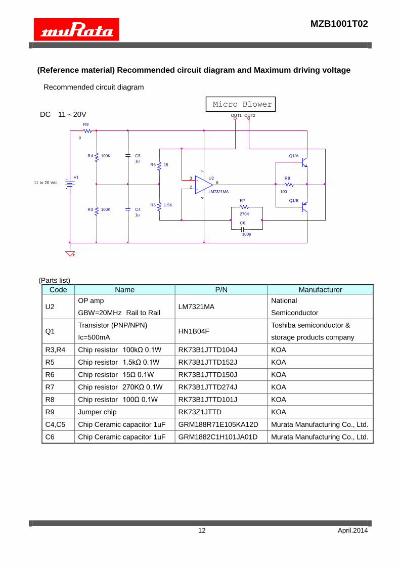
(Reference material) Recommended circuit diagram and Maximum driving voltage
Recommended circuit diagram
(Parts list)
Code Name P/N Manufacturer
U2 OP amp
GBW=20MHz Rail to Rail LM7321MA
National
Semiconductor
Q1 Transistor (PNP/NPN)
Ic=500mA HN1B04F
Toshiba semiconductor &
storage products company
R3,R4 Chip resistor 100kΩ 0.1W RK73B1JTTD104J KOA
R5 Chip resistor 1.5kΩ 0.1W RK73B1JTTD152J KOA
R6 Chip resistor 15Ω 0.1W RK73B1JTTD150J KOA
R7 Chip resistor 270KΩ 0.1W RK73B1JTTD274J KOA
R8 Chip resistor 100Ω 0.1W RK73B1JTTD101J KOA
R9 Jumper chip RK73Z1JTTD KOA
C4,C5 Chip Ceramic capacitor 1uF GRM188R71E105KA12D Murata Manufacturing Co., Ltd.
C6 Chip Ceramic capacitor 1uF GRM1882C1H101JA01D Murata Manufacturing Co., Ltd.
R6 15
R5 1.5K
C5
1u
C4
1u
C6
100p
Micro Blower
R7
270K
Q1/A
Q1/B
R8
100
R9
0
OUT1 OUT2
V1
11 to 20 Vdc
-
+U2
LM7321MA
3
26
74
R4 100K
R3 100K
DC 11~20V
MZB1001T02
13 April.2014
-14
-12
-10
-8
-6
-4
-2
0
2
4
6
8
10
12
14
-50 -30 -10 10 30 50
ブロア電圧
[V]
時間[us]
ブロア電圧の定義
①①①②
③
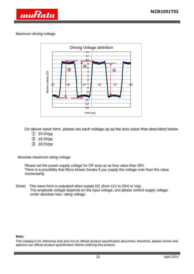
Maximum driving voltage
On above wave form, please set each voltage up as the less value than described below.
① 19.0Vpp
② 19.0Vpp
③ 18.5Vpp
Absolute maximum rating voltage
Please set the power-supply voltage for OP amp up as less value than 30V. There is a possibility that Micro blower breaks if you supply the voltage over than this value momentarily.
(Note) This wave form is outputted when supply DC (from 11V to 20V) to Vpp. The amplitude voltage depends on the input voltage, and please control supply voltage
under absolute max. rating voltage.
Note:
This catalog is for reference only and not an official product specification document, therefore, please review and approve our official product specification before ordering this product.
Driving Voltage definition
Time (us)
Blo
wer
voltage (
(V)
Mouser Electronics
Authorized Distributor
Click to View Pricing, Inventory, Delivery & Lifecycle Information: Murata:
MZB1001T02