Embed Size (px)
Citation preview
欧洲电气电子行业办事处
技术法规 . 标准化 . 认证的沟通网络
Unofficial English translation offered by EuropElectro, for reference only
Page 1 of 24 Landmark Tower II . Unit 0830/08. 8 North Dongsanhuan Road
Chaoyang District . Beijing 100004 . P.R. China
T +86 (0) 10 . 65 39 67 18 . F +86 (0) 10 . 65 39 67 19
[email protected] . www.europelectro.org
北京市朝阳区东三环北路 8 号 . 亮马大厦 2 座 0830/08 室 100004
电话 +86 (0) 10 . 65 39 67 15 . 传真 +86 (0) 10 . 65 39 67 19
[email protected] . www.europelectro.org
ICS 43.040.99
T 35
National Standard of the People’s Republic of China
GB/T 20234.2 -2011
Connection set for conductive charging of electric vehicles—
Part 2: AC charging coupler
电动汽车传导充电用连接装置 第 2 部分:交流充电接口
Issued on Dec. 22, 2011 Effective from March. 01, 2012
Issued by
General Administration of Quality Supervision, Inspection and Quarantine of the P. R. China Standardization Administration of the People's Republic of China
欧洲电气电子行业办事处
技术法规 . 标准化 . 认证的沟通网络
Unofficial English translation offered by EuropElectro, for reference only
Page 2 of 24 Landmark Tower II . Unit 0830/08. 8 North Dongsanhuan Road
Chaoyang District . Beijing 100004 . P.R. China
T +86 (0) 10 . 65 39 67 18 . F +86 (0) 10 . 65 39 67 19
[email protected] . www.europelectro.org
北京市朝阳区东三环北路 8 号 . 亮马大厦 2 座 0830/08 室 100004
电话 +86 (0) 10 . 65 39 67 15 . 传真 +86 (0) 10 . 65 39 67 19
[email protected] . www.europelectro.org
GB/T 20234.2 -2011
Foreword
GB/T20234 “Connection set for conductive charging of electric vehicles” is divided into three parts:
Part 1: General requirements;
Part 2: AC charging coupler;
Part 3: DC charging coupler.
This part is Part 2 of the GB/T 20234.
This part is drafted in accordance with the rules given in GB/T 1.1-2009.
This part is under the jurisdiction of the National Standardization Technical Committee on Vehicle (SAC/TC
114).
The main organizations to draft this part are China Automotive Technology and Research Center, State Grid
Corporation of China (SGCC), China National Electric Apparatus Research Institute Co., Ltd.
The organizations to join the drafting of this part are Tianjin Qingyuan Electric Vehicle Co., Ltd., China
Electricity Council, Electric Power Research Institute of China Southern Grid, Shenzhen BYD Auto Co., Ltd.,
Chery Automobile Co., Ltd., Shanghai Automotive Group Co., Ltd., Shenzhen New Energy Electric Power
Development Design Institute Co., Ltd., China Electric Power Research Institute, State Grid Electric Power
Research Institute, Electric Power Research Institute of the Guangdong Power Grid Corporation, Amphenol
precision connector (Shenzhen) Co., Ltd., Nanjing Mennekes Electric Appliances Co., Ltd. Beijing TOP Electric
Co.,Ltd., Dongfeng Electric Vehicle Co., Ltd..
The main drafters on this standard are Zhao Chunming, Jia Junguo, Luo Huaiping, Wu Bin, Liu Yingdong, Chen
Liangliang, Deng Weiguang, Zhang Jianhua, Meng Xiangfeng, He Yuntang, Wang Xiaomao, Ni Feng, Zhou
Guangrong, Wu Shangjie, Yang Xiaolun, Fang Yunzhou, Fan Xiaosong, Ni Haijin, Jin Weidong, Li Qing.
欧洲电气电子行业办事处
技术法规 . 标准化 . 认证的沟通网络
Unofficial English translation offered by EuropElectro, for reference only
Page 3 of 24 Landmark Tower II . Unit 0830/08. 8 North Dongsanhuan Road
Chaoyang District . Beijing 100004 . P.R. China
T +86 (0) 10 . 65 39 67 18 . F +86 (0) 10 . 65 39 67 19
[email protected] . www.europelectro.org
北京市朝阳区东三环北路 8 号 . 亮马大厦 2 座 0830/08 室 100004
电话 +86 (0) 10 . 65 39 67 15 . 传真 +86 (0) 10 . 65 39 67 19
[email protected] . www.europelectro.org
GB/T 20234.2 -2011
Connection set for conductive charging of electric vehicles—
Part 2: AC charging coupler
1 Scope
This part of GB/T 20234 provides the general requirements, functional definition, types and structure,
parameters and dimensions on the AC charging coupler for conductive charging of electric vehicles.
This part applies to the AC charging coupler for connection set for conductive charging of electric vehicles, its
rated voltage does not exceed 440 V (AC), frequency is 50Hz, rated current does not exceed 32 A (AC).
If the power supply coupler for the AC charging coupler adopted the standardized plugs and sockets in line with
the GB 2099.1, then the structure dimensions and installation dimensions provided by Appendix B and
Appendix Cof this part are not applicable to these plugs and sockets.
2 Normative references
The following referenced documents are indispensable for the application of this document. For dated
references, only the edition cited applies. For undated references, the latest edition of the referenced
document (including any amendments) applies.
GB/T 20234.1 Connection set for conductive charging of electric vehicles — Part 1: General requirements
3 Terms and definition
The terms and definitions defined in GB/T 20234.1 are applicable to this document.
4 General requirements
The technical requirements and test method for the AC charging coupler shall conform to the provisions of GB/T
20234.1.
5 The rated values of the AC charging coupler
The rated values of the AC charging coupler see table 1.
Table 1 The rated values of the AC charging coupler
Rated voltage / V Rated current / A
250/440 16
32
6 The functions of charging coupler
欧洲电气电子行业办事处
技术法规 . 标准化 . 认证的沟通网络
Unofficial English translation offered by EuropElectro, for reference only
Page 4 of 24 Landmark Tower II . Unit 0830/08. 8 North Dongsanhuan Road
Chaoyang District . Beijing 100004 . P.R. China
T +86 (0) 10 . 65 39 67 18 . F +86 (0) 10 . 65 39 67 19
[email protected] . www.europelectro.org
北京市朝阳区东三环北路 8 号 . 亮马大厦 2 座 0830/08 室 100004
电话 +86 (0) 10 . 65 39 67 15 . 传真 +86 (0) 10 . 65 39 67 19
[email protected] . www.europelectro.org
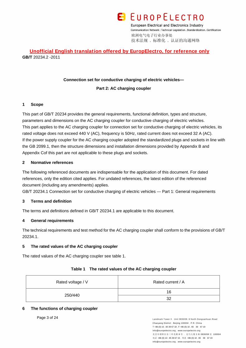
6.1 Electrical parameter values and functions
The vehicle connector and the power supply coupler of charging mode 3 include 7 pairs of contactors
respectively, their electrical parameter values and functional definitions see Table 2.
Table 2 Electrical parameter values and functional definitions of the contactors
Contactor number/
marking Rated voltage and rated current Functional definitions
1 (L) 250 V/440 V 16 A/32 A AC power supply
2 (NC1) Spare contactors
3 (NC2) Spare contactors
4 (N) 250 V/440 V 16 A/32 A Neutral wire
5 ( ) PE, connecting to the earth wires of the
power supply unit and the vehicle body
6 (CC) 30 V 2 A Connect confirm for charging, see
Appendix A
7 (CP) 30 V 2 A Control confirm, see Appendix A
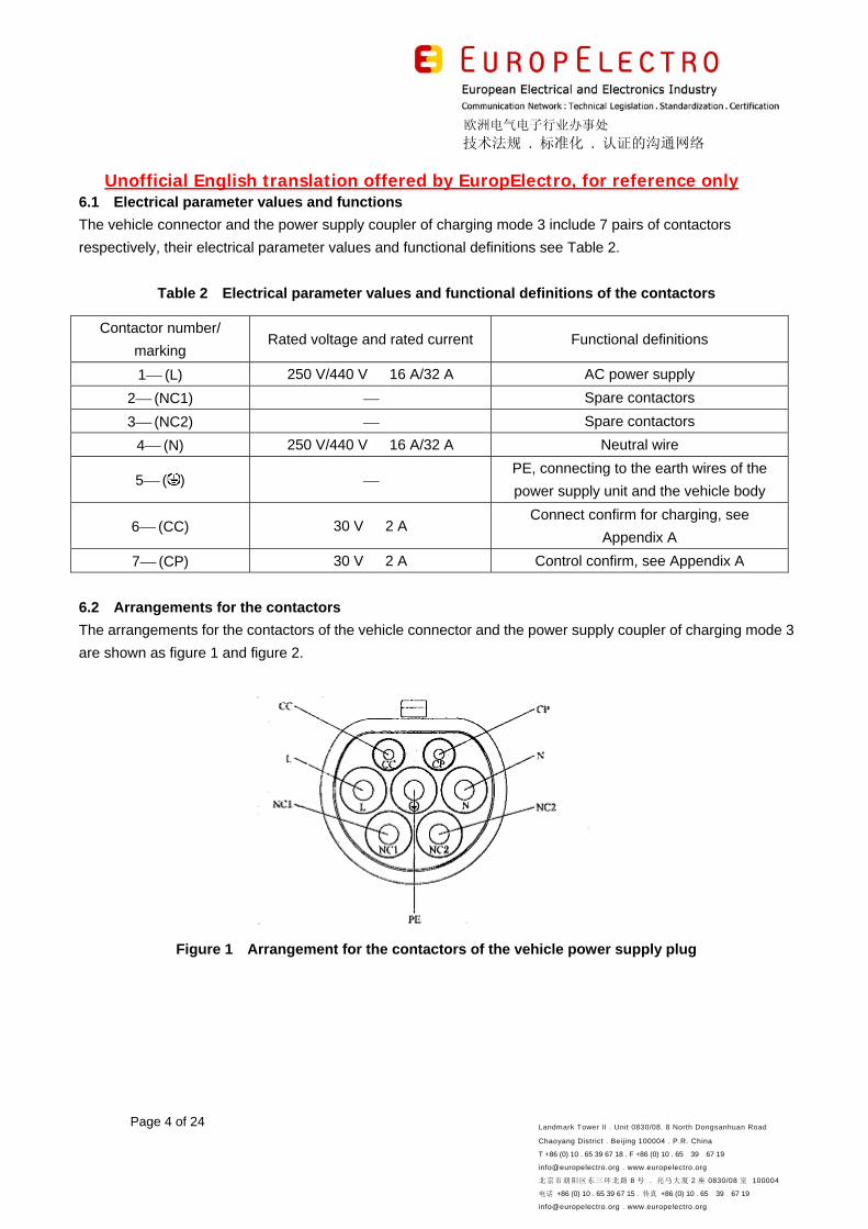
6.2 Arrangements for the contactors
The arrangements for the contactors of the vehicle connector and the power supply coupler of charging mode 3
are shown as figure 1 and figure 2.
Figure 1 Arrangement for the contactors of the vehicle power supply plug
欧洲电气电子行业办事处
技术法规 . 标准化 . 认证的沟通网络
Unofficial English translation offered by EuropElectro, for reference only
Page 5 of 24 Landmark Tower II . Unit 0830/08. 8 North Dongsanhuan Road
Chaoyang District . Beijing 100004 . P.R. China
T +86 (0) 10 . 65 39 67 18 . F +86 (0) 10 . 65 39 67 19
[email protected] . www.europelectro.org
北京市朝阳区东三环北路 8 号 . 亮马大厦 2 座 0830/08 室 100004
电话 +86 (0) 10 . 65 39 67 15 . 传真 +86 (0) 10 . 65 39 67 19
[email protected] . www.europelectro.org
Figure 2 Arrangement for the contactors of the vehicle power supply socket
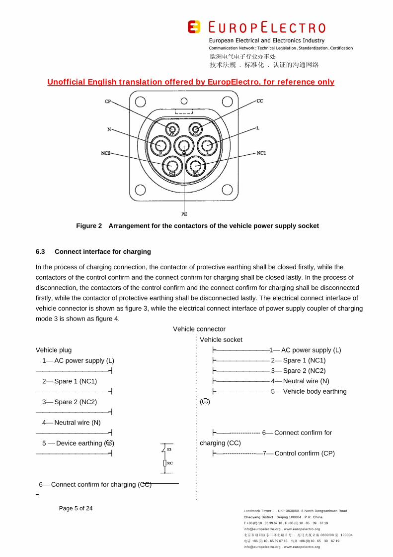
6.3 Connect interface for charging
In the process of charging connection, the contactor of protective earthing shall be closed firstly, while the
contactors of the control confirm and the connect confirm for charging shall be closed lastly. In the process of
disconnection, the contactors of the control confirm and the connect confirm for charging shall be disconnected
firstly, while the contactor of protective earthing shall be disconnected lastly. The electrical connect interface of
vehicle connector is shown as figure 3, while the electrical connect interface of power supply coupler of charging
mode 3 is shown as figure 4.
Vehicle connector
Vehicle plug
1 AC power supply (L)
┥
2 Spare 1 (NC1)
┥
3 Spare 2 (NC2)
┥
4 Neutral wire (N)
┥
5 Device earthing ( )
┥
6 Connect confirm for charging (CC)
┥
Vehicle socket
┝1 AC power supply (L)
┝ 2 Spare 1 (NC1)
┝ 3 Spare 2 (NC2)
┝ 4 Neutral wire (N)
┝ 5 Vehicle body earthing
( )
┝-------------- 6 Connect confirm for
charging (CC)
┝---------------7 Control confirm (CP)
欧洲电气电子行业办事处
技术法规 . 标准化 . 认证的沟通网络
Unofficial English translation offered by EuropElectro, for reference only
Page 6 of 24 Landmark Tower II . Unit 0830/08. 8 North Dongsanhuan Road
Chaoyang District . Beijing 100004 . P.R. China
T +86 (0) 10 . 65 39 67 18 . F +86 (0) 10 . 65 39 67 19
[email protected] . www.europelectro.org
北京市朝阳区东三环北路 8 号 . 亮马大厦 2 座 0830/08 室 100004
电话 +86 (0) 10 . 65 39 67 15 . 传真 +86 (0) 10 . 65 39 67 19
[email protected] . www.europelectro.org
7 Control confirm (CP)
-------┥
Figure 3 Schematic diagram for electrical connect interface of vehicle
Power supply coupler
Power
supply plug
1 AC power supply (L)
┥
2 Spare 1 (NC1)
┥
3 Spare 2 (NC2)
┥
4 Neutral wire (N)
┥
5 Vehicle body earthing ( )
┥
6 Connect confirm for charging (CC)
┥
7 Control confirm (CP)
------┥
Power supply socket
┝1 AC power supply (L)
┝ 2 Spare 1 (NC1)
┝ 3 Spare 2 (NC2)
┝ 4 Neutral wire (N)
┝ 5 Device earthing ( )
┝-------------- 6 Connect confirm for
charging (CC)
┝---------------7 Control confirm (CP)
Figure 4 Schematic diagram for electrical connect interface of power supply coupler of charging mode
3
7 Structure dimensions and installation dimensions
The structure dimensions of AC charging coupler shall conform to the provisions of Appendix B, the installation
dimensions refer to Appendix C and Appendix D.
Appendix A
(Informative)
Control-steering circuit and control principle
A.1 Control-steering circuit
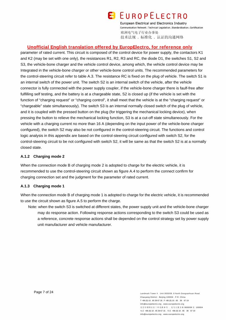
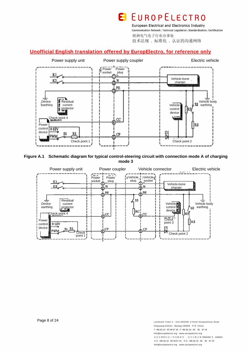
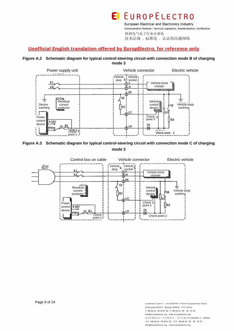
A.1.1 Charging mode 3
When the charging mode 3 is adopted to charge for the electric vehicle, it is recommended to use the typical
control-steering circuits shown as figure A.1 (connection mode A), figure A.2 (connection mode B) and figure
A.3 (connection mode C) to perform the connect confirm for charging connection set and the judgment for the
欧洲电气电子行业办事处
技术法规 . 标准化 . 认证的沟通网络
Unofficial English translation offered by EuropElectro, for reference only
Page 7 of 24 Landmark Tower II . Unit 0830/08. 8 North Dongsanhuan Road
Chaoyang District . Beijing 100004 . P.R. China
T +86 (0) 10 . 65 39 67 18 . F +86 (0) 10 . 65 39 67 19
[email protected] . www.europelectro.org
北京市朝阳区东三环北路 8 号 . 亮马大厦 2 座 0830/08 室 100004
电话 +86 (0) 10 . 65 39 67 15 . 传真 +86 (0) 10 . 65 39 67 19
[email protected] . www.europelectro.org
parameter of rated current. This circuit is composed of the control device for power supply, the contactors K1
and K2 (may be set with one only), the resistances R1, R2, R3 and RC, the diode D1, the switches S1, S2 and
S3, the vehicle-bone charger and the vehicle control device, among which, the vehicle control device may be
Integrated in the vehicle-bone charger or other vehicle-bone control units. The recommended parameters for
the control-steering circuit refer to table A.3. The resistance RC is fixed on the plug of vehicle. The switch S1 is
an internal switch of the power unit. The switch S2 is an internal switch of the vehicle, after the vehicle
connector is fully connected with the power supply coupler, if the vehicle-bone charger there is faulf-free after
fulfilling self testing, and the battery is at a chargeable state, S2 is closed up (if the vehicle is set with the
function of “charging request” or “charging control”, it shall meet that the vehicle is at the “charging request” or
“chargeable” state simultaneously). The switch S3 is an internal normally closed switch of the plug of vehicle,
and it is coupled with the pressed button on the plug (for triggering the mechanical locking device), when
pressing the button to relieve the mechanical locking function, S3 is at a cut-off state simultaneously. For the
vehicle with a charging current no more than 16 A (depending on the input power of the vehicle-bone charger
configured), the switch S2 may also be not configured in the control-steering circuit. The functions and control
logic analysis in this appendix are based on the control-steering circuit configured with switch S2, for the
control-steering circuit to be not configured with switch S2, it will be same as that the switch S2 is at a normally
closed state.
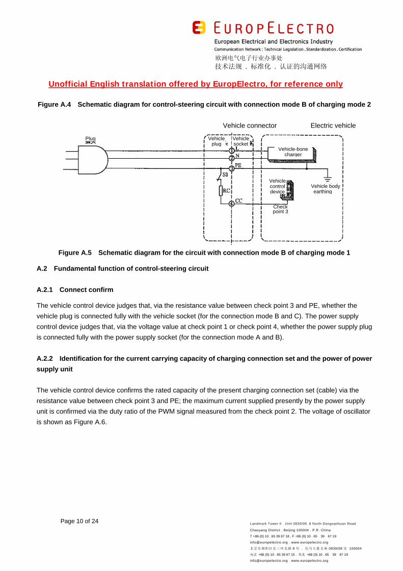
A.1.2 Charging mode 2
When the connection mode B of charging mode 2 is adopted to charge for the electric vehicle, it is
recommended to use the control-steering circuit shown as figure A.4 to perform the connect confirm for
charging connection set and the judgment for the parameter of rated current.
A.1.3 Charging mode 1
When the connection mode B of charging mode 1 is adopted to charge for the electric vehicle, it is recommended
to use the circuit shown as figure A.5 to perform the charge.
Note: when the switch S3 is switched at different states, the power supply unit and the vehicle-bone charger
may do response action. Following response actions corresponding to the switch S3 could be used as
a reference, concrete response actions shall be depended on the control strategy set by power supply
unit manufacturer and vehicle manufacturer.
欧洲电气电子行业办事处
技术法规 . 标准化 . 认证的沟通网络
Unofficial English translation offered by EuropElectro, for reference only
Page 8 of 24 Landmark Tower II . Unit 0830/08. 8 North Dongsanhuan Road
Chaoyang District . Beijing 100004 . P.R. China
T +86 (0) 10 . 65 39 67 18 . F +86 (0) 10 . 65 39 67 19
[email protected] . www.europelectro.org
北京市朝阳区东三环北路 8 号 . 亮马大厦 2 座 0830/08 室 100004
电话 +86 (0) 10 . 65 39 67 15 . 传真 +86 (0) 10 . 65 39 67 19
[email protected] . www.europelectro.org
Power supply unit Power supply coupler Electric vehicle
Figure A.1 Schematic diagram for typical control-steering circuit with connection mode A of charging mode 3
Power supply unit Power coupler Vehicle connector Electric vehicle
Vehicle-bone charger
Vehicle control device
Vehicle body earthing
Powersocket
Check point 2 Check point 1
Device earthing
Residual current
protector
Check point 4
Power control device
Powerplug
Power socket
Powerplug
Vehiclesocket
Vehicleplug
Vehicle-bone charger
Device earthing
Residual current
protector
Check point 4
Power control device
Check point 1
Checkpoint 3
Check point 2
Vehicle body earthing
Vehicle control device
欧洲电气电子行业办事处
技术法规 . 标准化 . 认证的沟通网络
Unofficial English translation offered by EuropElectro, for reference only
Page 9 of 24 Landmark Tower II . Unit 0830/08. 8 North Dongsanhuan Road
Chaoyang District . Beijing 100004 . P.R. China
T +86 (0) 10 . 65 39 67 18 . F +86 (0) 10 . 65 39 67 19
[email protected] . www.europelectro.org
北京市朝阳区东三环北路 8 号 . 亮马大厦 2 座 0830/08 室 100004
电话 +86 (0) 10 . 65 39 67 15 . 传真 +86 (0) 10 . 65 39 67 19
[email protected] . www.europelectro.org
Figure A.2 Schematic diagram for typical control-steering circuit with connection mode B of charging
mode 3
Power supply unit Vehicle connector Electric vehicle
Figure A.3 Schematic diagram for typical control-steering circuit with connection mode C of charging
mode 3
Control box on cable Vehicle connector Electric vehicle
Check point 2
Vehicleplug
Vehiclesocket
Vehicle-bone charger
Device earthing
Residual current
protector
Vehiclecontroldevice
Vehicle body earthing
Checkpoint 3
Checkpoint 1
Power control device
Plug Vehicleplug
Vehiclesocket
Vehicle-bonecharger
Residual current
protector
Powercontroldevice
Vehicle body earthing
Vehiclecontroldevice
Checkpoint 3
Check point 2
Check point 1
欧洲电气电子行业办事处
技术法规 . 标准化 . 认证的沟通网络
Unofficial English translation offered by EuropElectro, for reference only
Page 10 of 24 Landmark Tower II . Unit 0830/08. 8 North Dongsanhuan Road
Chaoyang District . Beijing 100004 . P.R. China
T +86 (0) 10 . 65 39 67 18 . F +86 (0) 10 . 65 39 67 19
[email protected] . www.europelectro.org
北京市朝阳区东三环北路 8 号 . 亮马大厦 2 座 0830/08 室 100004
电话 +86 (0) 10 . 65 39 67 15 . 传真 +86 (0) 10 . 65 39 67 19
[email protected] . www.europelectro.org
Figure A.4 Schematic diagram for control-steering circuit with connection mode B of charging mode 2
Vehicle connector Electric vehicle
Figure A.5 Schematic diagram for the circuit with connection mode B of charging mode 1
A.2 Fundamental function of control-steering circuit
A.2.1 Connect confirm
The vehicle control device judges that, via the resistance value between check point 3 and PE, whether the
vehicle plug is connected fully with the vehicle socket (for the connection mode B and C). The power supply
control device judges that, via the voltage value at check point 1 or check point 4, whether the power supply plug
is connected fully with the power supply socket (for the connection mode A and B).
A.2.2 Identification for the current carrying capacity of charging connection set and the power of power
supply unit
The vehicle control device confirms the rated capacity of the present charging connection set (cable) via the
resistance value between check point 3 and PE; the maximum current supplied presently by the power supply
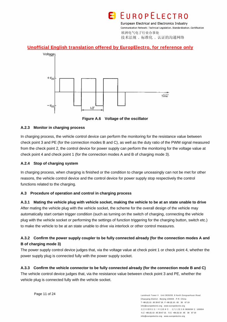
unit is confirmed via the duty ratio of the PWM signal measured from the check point 2. The voltage of oscillator
is shown as Figure A.6.
Plug Vehicleplug
Vehiclesocket
Vehicle-bone charger
Vehicle body earthing
Vehicle control device
Check point 3
欧洲电气电子行业办事处
技术法规 . 标准化 . 认证的沟通网络
Unofficial English translation offered by EuropElectro, for reference only
Page 11 of 24 Landmark Tower II . Unit 0830/08. 8 North Dongsanhuan Road
Chaoyang District . Beijing 100004 . P.R. China
T +86 (0) 10 . 65 39 67 18 . F +86 (0) 10 . 65 39 67 19
[email protected] . www.europelectro.org
北京市朝阳区东三环北路 8 号 . 亮马大厦 2 座 0830/08 室 100004
电话 +86 (0) 10 . 65 39 67 15 . 传真 +86 (0) 10 . 65 39 67 19
[email protected] . www.europelectro.org
Figure A.6 Voltage of the oscillator
A.2.3 Monitor in charging process
In charging process, the vehicle control device can perform the monitoring for the resistance value between
check point 3 and PE (for the connection modes B and C), as well as the duty ratio of the PWM signal measured
from the check point 2, the control device for power supply can perform the monitoring for the voltage value at
check point 4 and check point 1 (for the connection modes A and B of charging mode 3).
A.2.4 Stop of charging system
In charging process, when charging is finished or the condition to charge unceasingly can not be met for other
reasons, the vehicle control device and the control device for power supply stop respectively the control
functions related to the charging.
A.3 Procedure of operation and control in charging process
A.3.1 Mating the vehicle plug with vehicle socket, making the vehicle to be at an state unable to drive
After mating the vehicle plug with the vehicle socket, the scheme for the overall design of the vehicle may
automatically start certain trigger condition (such as turning on the switch of charging, connecting the vehicle
plug with the vehicle socket or performing the settings of function triggering for the charging button, switch etc.)
to make the vehicle to be at an state unable to drive via interlock or other control measures.
A.3.2 Confirm the power supply coupler to be fully connected already (for the connection modes A and
B of charging mode 3)
The power supply control device judges that, via the voltage value at check point 1 or check point 4, whether the
power supply plug is connected fully with the power supply socket.
A.3.3 Confirm the vehicle connector to be fully connected already (for the connection mode B and C)
The vehicle control device judges that, via the resistance value between check point 3 and PE, whether the
vehicle plug is connected fully with the vehicle socket.
Time
Voltage
欧洲电气电子行业办事处
技术法规 . 标准化 . 认证的沟通网络
Unofficial English translation offered by EuropElectro, for reference only
Page 12 of 24 Landmark Tower II . Unit 0830/08. 8 North Dongsanhuan Road
Chaoyang District . Beijing 100004 . P.R. China
T +86 (0) 10 . 65 39 67 18 . F +86 (0) 10 . 65 39 67 19
[email protected] . www.europelectro.org
北京市朝阳区东三环北路 8 号 . 亮马大厦 2 座 0830/08 室 100004
电话 +86 (0) 10 . 65 39 67 15 . 传真 +86 (0) 10 . 65 39 67 19
[email protected] . www.europelectro.org
A.3.4 Confirm the charging connection set to be fully connected already
After the operator fulfills the settings for startup of charging for the power supply unit, if it is faulf-free, and the
power supply coupler has benn fully connected (for the connection modes A and B of charging mode 3), then the
switch S1 is switched to the PWM connection state from the state connected to 12 V+, and the control device for
power supply sends out the PWM signals. The power supply control device judges that, via the voltage value at
check point 1 or check point 4, whether the charging connection set is connected fully. The vehicle control device
judges that, via the PWM signal measured from the check point 2, whether the charging connection set is
connected fully.
A.3.5 The vehicle in train
Under the condition of that a self-check for the vehicle-bone charger is finished, and the battery is at the
chargeable state, the vehicle control device closes the switch S2 (if the vehicle is set with the function of
“charging request” or “charging control”, it shall meet that the vehicle is at the “charging request” or “chargeable”
state simultaneously).
A.3.6 The power supply control device in train
The power supply control device judges that, via the voltage value measured at check point 1, whether the
vehicle is in train. When the peak voltage at check point 1 is the corresponding voltage value of mode 3 in table
A.2, then the power supply control device makes the power supply circuit to be turned on via closing the
contactors K1 and K2.
A.3.7 Starting of the charging system
A.3.7.1 After the electrical connection for electric vehicle and power supply unit is established, The vehicle
control device confirms the maximum power supply capacity of the power supply unit via judging the duty ratio
of the PWM signal measured from the check point 2, and the rated capacity of the cable is confirmed via the
resistance value measured between check point 3 and PE. The connection state of the vehicle connector as
well as the resistance value see table A.1. The vehicle control device performs the comparison for the
maximum current value supplied presently by the power supply unit, the rated input current value of the
vehicle-bone charger as well as the rated capacity of the cable, and set their minimum value to be as the
allowable maximum input current at present for the vehicle-bone charger. When the vehicle control device
judges that the charging connection set has been fully connected, and after the setting for the allowable
maximum input current for the vehicle-bone charger has been fulfilled, the vehicle-bone charger starts to
perform the charging for the electric vehicle.
A.3.7.2 When the vehicle connector is at the state of full connection, and the vehicle control device does not
receive the PWM signals from the check point 2, if the vehicle control device receives the signal from the driver
to request for forced charge (require to set the manual triggering device on the vehicle for the request of
charging), the power setting for the vehicle-bone charger shall be based on the mode with an input current no
more than 13 A to perform the charging for electric vehicle. In charging process, if the PWM signals from the
欧洲电气电子行业办事处
技术法规 . 标准化 . 认证的沟通网络
Unofficial English translation offered by EuropElectro, for reference only
Page 13 of 24 Landmark Tower II . Unit 0830/08. 8 North Dongsanhuan Road
Chaoyang District . Beijing 100004 . P.R. China
T +86 (0) 10 . 65 39 67 18 . F +86 (0) 10 . 65 39 67 19
[email protected] . www.europelectro.org
北京市朝阳区东三环北路 8 号 . 亮马大厦 2 座 0830/08 室 100004
电话 +86 (0) 10 . 65 39 67 15 . 传真 +86 (0) 10 . 65 39 67 19
[email protected] . www.europelectro.org
check point 2 are received, then the setting for the allowable maximum input current of the vehicle-bone charger
depends on the maximum power supply capacity of power supply unit and the minimum rated current of
vehicle-bone charger.
A.3.8 Check the change of the connection state of charging coupler and the power supply capacity of
power supply unit
A.3.8.1 In charging process, the connection state of vehicle connector and power supply couple is confirmed by
the vehicle control device via periodic monitoring check point 2 and check point 3, and by the control device for
power supply via periodic monitoring check point 1 and check point 4, the monitoring cycle is no more than 50
ms.
A.3.8.2 The vehicle control device performs uninterrupted detection for the PWM signals from the check point 2,
when theduty ratio is changed, the vehicle control device will instantaneously adjust the output power of
vehicle-bone charger, the detection cycle is no more than 5 s.
A.3.9 Charge ending or stopping under normal condition
A.3.9.1 In charging process, when the charge reaches the ending condition set in the vehicle, or the driver
implements a command of charge stopping for the vehicle, the vehicle control device cuts off the switch S2, and
makes the vehicle-bone charger to be at the charge stopping state.
A.3.9.2 In charging process, when the charge reaches the ending condition set by the operator, or the operator
implemented a command of charge stopping for the control device for power supply or detected the switch S2
has been cut off, then the control device for power supply switches the switch S1 to +12 V connection state,
and cuts off the AC power supply circuit via cutting off the contactors K1 and K2.
A.3.10 Charge ending or stopping under abnormal condition
A.3.10.1 In charging process, the vehicle control device judges the connection state of the vehicle plug and the
vehicle socket via the resistance value measured between check point 3 and PE (for the connection mode B and
C), if it is judged that the switch S3 is changed into cut-off (state B) from close, and lasted for a certain time (such
as 300 ms), then the vehicle control device controls the vehicle-bone charger to stop charge and cuts off S2.
A.3.10.2 In charging process, the vehicle control device judges the connection state of the vehicle plug and the
vehicle socket via the resistance value measured between check point 3 and PE (for the connection mode B and
C), if it is judged that the vehicle connector is changed into cut-off (state A) from full connection, then the vehicle
control device controls the vehicle-bone charger to stop charge and cuts off S2.
A.3.10.3 In charging process, the vehicle control device carries out the test through detecting the PWM signals
from the check point 2, when the signals interrupt, the vehicle control device controls the vehicle-bone charger to
stop charge.
A.3.10.4 In charging process, if the voltage values at check point 1 are 12 V (state 1), 9 V (state 2) or other
states to be not 6 V (state 3), then the control device for power supply cuts off the AC power supply circuit.
A.3.10.5 In charging process, the control device for power supply carries out the test through detecting the
check point 4 (for the connection modes A and B of charging mode 3), the control device for power supply
switches the switch S1 to +12 V connection state, and cuts off the AC power supply circuit.
欧洲电气电子行业办事处
技术法规 . 标准化 . 认证的沟通网络
Unofficial English translation offered by EuropElectro, for reference only
Page 14 of 24 Landmark Tower II . Unit 0830/08. 8 North Dongsanhuan Road
Chaoyang District . Beijing 100004 . P.R. China
T +86 (0) 10 . 65 39 67 18 . F +86 (0) 10 . 65 39 67 19
[email protected] . www.europelectro.org
北京市朝阳区东三环北路 8 号 . 亮马大厦 2 座 0830/08 室 100004
电话 +86 (0) 10 . 65 39 67 15 . 传真 +86 (0) 10 . 65 39 67 19
[email protected] . www.europelectro.org
A.3.10.6 In charging process, if the residual current protector (residual current circuit breaker) acts, then the
vehicle-bone charger is at an over low voltage state, the vehicle control device cuts off the switch S2.
Note: If the control device for power supply cuts off the power supply circuit and ends the charge for the
reason that the charging connection set is changed into cut-off (state A and state 1) from full
connection, then the operator shall check and recover the connection, and the charge will be able to
proceed only when the charging setting is restarted.
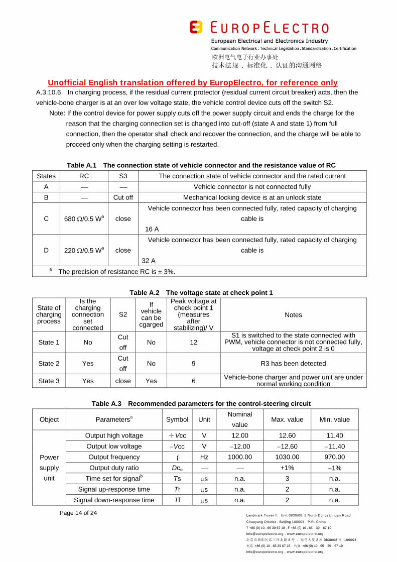
Table A.1 The connection state of vehicle connector and the resistance value of RC
States RC S3 The connection state of vehicle connector and the rated current
A Vehicle connector is not connected fully
B Cut off Mechanical locking device is at an unlock state
C 680 /0.5 Wa close
Vehicle connector has been connected fully, rated capacity of charging
cable is
16 A
D 220 /0.5 Wa close
Vehicle connector has been connected fully, rated capacity of charging
cable is
32 A
a The precision of resistance RC is 3%.
Table A.2 The voltage state at check point 1
State of charging process
Is the charging
connection set
connected
S2
If vehicle can be
cgarged
Peak voltage at check point 1
(measures after
stabilizing)/ V
Notes
State 1 No Cut
off No 12
S1 is switched to the state connected with PWM, vehicle connector is not connected fully,
voltage at check point 2 is 0
State 2 Yes Cut
off No 9 R3 has been detected
State 3 Yes close Yes 6 Vehicle-bone charger and power unit are under normal working condition
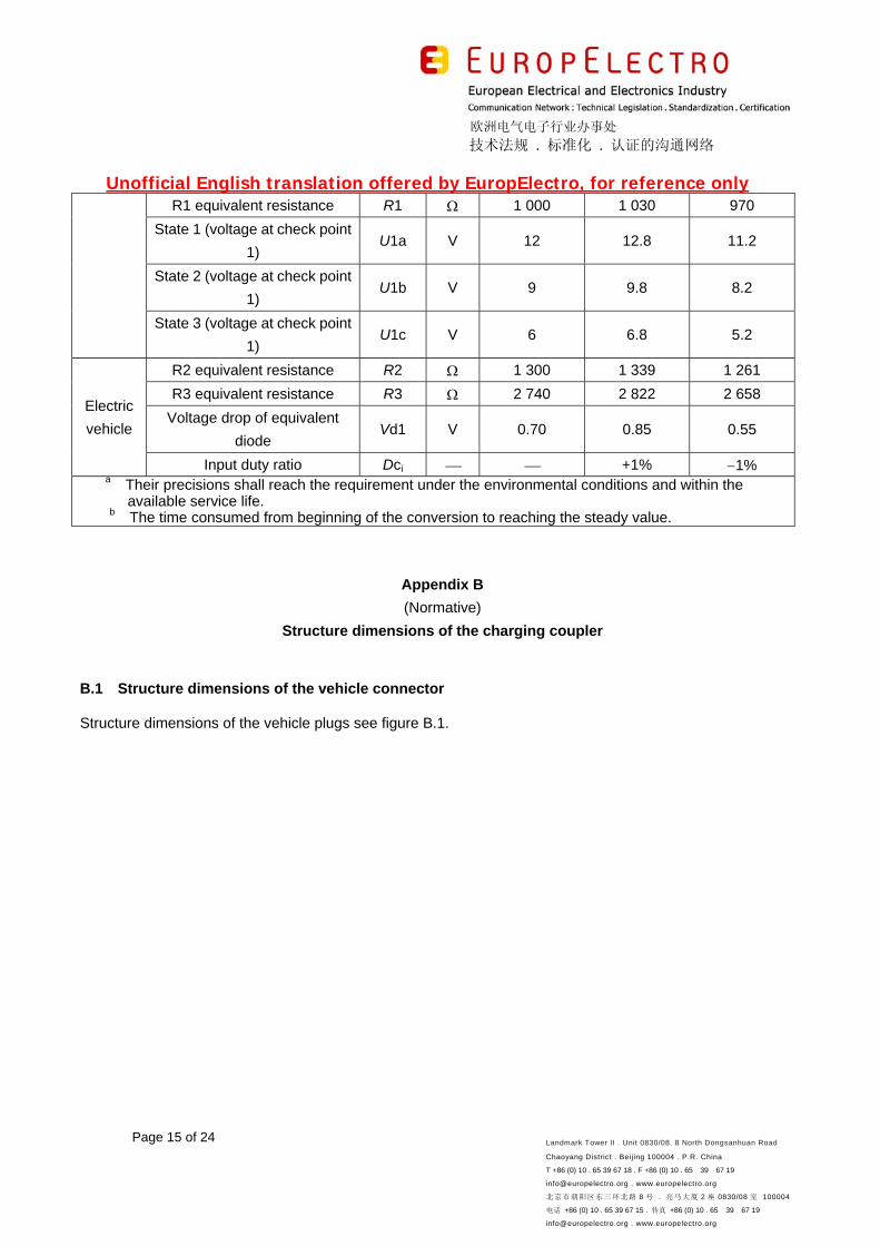
Table A.3 Recommended parameters for the control-steering circuit
Object Parametersa Symbol Unit Nominal
value Max. value Min. value
Power
supply
unit
Output high voltage +Vcc V 12.00 12.60 11.40
Output low voltage Vcc V 12.00 12.60 11.40
Output frequency Hz 1000.00 1030.00 970.00
Output duty ratio Dco +1% 1%
Time set for signalb Ts s n.a. 3 n.a.
Signal up-response time Tr s n.a. 2 n.a.
Signal down-response time Tf s n.a. 2 n.a.
欧洲电气电子行业办事处
技术法规 . 标准化 . 认证的沟通网络
Unofficial English translation offered by EuropElectro, for reference only
Page 15 of 24 Landmark Tower II . Unit 0830/08. 8 North Dongsanhuan Road
Chaoyang District . Beijing 100004 . P.R. China
T +86 (0) 10 . 65 39 67 18 . F +86 (0) 10 . 65 39 67 19
[email protected] . www.europelectro.org
北京市朝阳区东三环北路 8 号 . 亮马大厦 2 座 0830/08 室 100004
电话 +86 (0) 10 . 65 39 67 15 . 传真 +86 (0) 10 . 65 39 67 19
[email protected] . www.europelectro.org
R1 equivalent resistance R1 1 000 1 030 970
State 1 (voltage at check point
1) U1a V 12 12.8 11.2
State 2 (voltage at check point
1) U1b V 9 9.8 8.2
State 3 (voltage at check point
1) U1c V 6 6.8 5.2
Electric
vehicle
R2 equivalent resistance R2 1 300 1 339 1 261
R3 equivalent resistance R3 2 740 2 822 2 658
Voltage drop of equivalent
diode Vd1 V 0.70 0.85 0.55
Input duty ratio Dci +1% 1% a Their precisions shall reach the requirement under the environmental conditions and within the
available service life. b The time consumed from beginning of the conversion to reaching the steady value.
Appendix B
(Normative)
Structure dimensions of the charging coupler
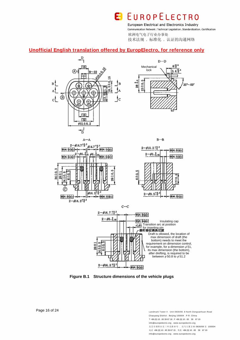
B.1 Structure dimensions of the vehicle connector
Structure dimensions of the vehicle plugs see figure B.1.
欧洲电气电子行业办事处
技术法规 . 标准化 . 认证的沟通网络
Unofficial English translation offered by EuropElectro, for reference only
Page 16 of 24 Landmark Tower II . Unit 0830/08. 8 North Dongsanhuan Road
Chaoyang District . Beijing 100004 . P.R. China
T +86 (0) 10 . 65 39 67 18 . F +86 (0) 10 . 65 39 67 19
[email protected] . www.europelectro.org
北京市朝阳区东三环北路 8 号 . 亮马大厦 2 座 0830/08 室 100004
电话 +86 (0) 10 . 65 39 67 15 . 传真 +86 (0) 10 . 65 39 67 19
[email protected] . www.europelectro.org
Figure B.1 Structure dimensions of the vehicle plugs
Transition arc at position for inserting pin
Mechanicallock
Insulating cap
Draft is ollowed, the location of max dimension of draft (the bottom) needs to meet the
requirement on dimension control, for example, for a dimension 51,
its max dimension (the bottom), after drefting, is required to be
between 50.8 to 51.2
欧洲电气电子行业办事处
技术法规 . 标准化 . 认证的沟通网络
Unofficial English translation offered by EuropElectro, for reference only
Page 17 of 24 Landmark Tower II . Unit 0830/08. 8 North Dongsanhuan Road
Chaoyang District . Beijing 100004 . P.R. China
T +86 (0) 10 . 65 39 67 18 . F +86 (0) 10 . 65 39 67 19
[email protected] . www.europelectro.org
北京市朝阳区东三环北路 8 号 . 亮马大厦 2 座 0830/08 室 100004
电话 +86 (0) 10 . 65 39 67 15 . 传真 +86 (0) 10 . 65 39 67 19
[email protected] . www.europelectro.org
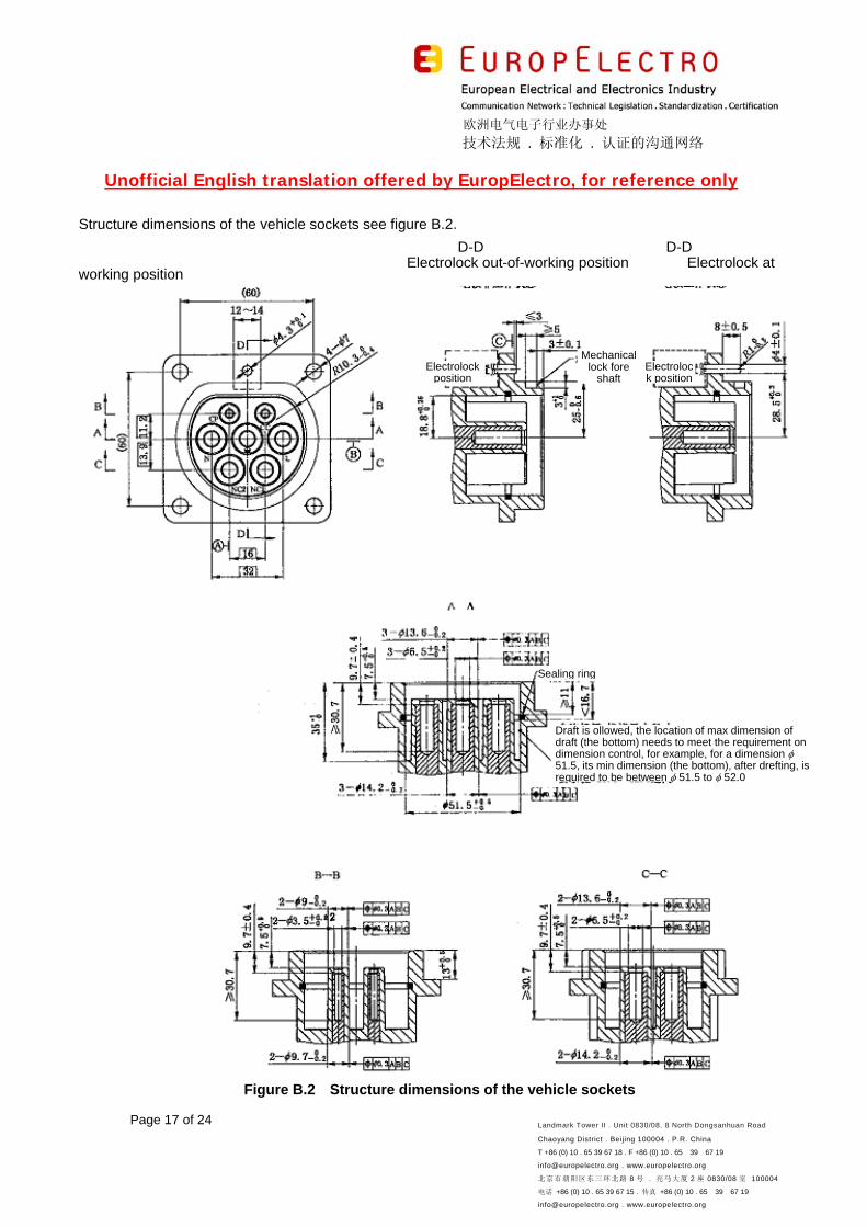
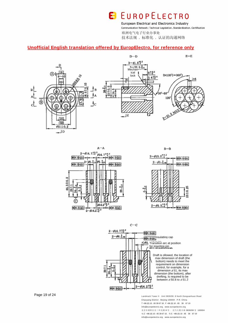
Structure dimensions of the vehicle sockets see figure B.2.
D-D D-D Electrolock out-of-working position Electrolock at working position
Figure B.2 Structure dimensions of the vehicle sockets
Mechanical lock fore
shaft Electrolock position
Electrolockposition
Sealing ring
Draft is ollowed, the location of max dimension of draft (the bottom) needs to meet the requirement on dimension control, for example, for a dimension 51.5, its min dimension (the bottom), after drefting, is required to be between 51.5 to 52.0
欧洲电气电子行业办事处
技术法规 . 标准化 . 认证的沟通网络
Unofficial English translation offered by EuropElectro, for reference only
Page 18 of 24 Landmark Tower II . Unit 0830/08. 8 North Dongsanhuan Road
Chaoyang District . Beijing 100004 . P.R. China
T +86 (0) 10 . 65 39 67 18 . F +86 (0) 10 . 65 39 67 19
[email protected] . www.europelectro.org
北京市朝阳区东三环北路 8 号 . 亮马大厦 2 座 0830/08 室 100004
电话 +86 (0) 10 . 65 39 67 15 . 传真 +86 (0) 10 . 65 39 67 19
[email protected] . www.europelectro.org
B.2 Structure dimensions of the power supply coupler of charging mode 3
Structure dimensions of the power supply plugs of charging mode 3 see figure B.3.
欧洲电气电子行业办事处
技术法规 . 标准化 . 认证的沟通网络
Unofficial English translation offered by EuropElectro, for reference only
Page 19 of 24 Landmark Tower II . Unit 0830/08. 8 North Dongsanhuan Road
Chaoyang District . Beijing 100004 . P.R. China
T +86 (0) 10 . 65 39 67 18 . F +86 (0) 10 . 65 39 67 19
[email protected] . www.europelectro.org
北京市朝阳区东三环北路 8 号 . 亮马大厦 2 座 0830/08 室 100004
电话 +86 (0) 10 . 65 39 67 15 . 传真 +86 (0) 10 . 65 39 67 19
[email protected] . www.europelectro.org
Mechanical lock
Insulating cap
Transition arc at position for inserting pin
Draft is ollowed, the location of max dimension of draft (the bottom) needs to meet the requirement on dimension control, for example, for a dimension 51, its max
dimension (the bottom), after drefting, is required to be between 50.8 to 51.2
欧洲电气电子行业办事处
技术法规 . 标准化 . 认证的沟通网络
Unofficial English translation offered by EuropElectro, for reference only
Page 20 of 24 Landmark Tower II . Unit 0830/08. 8 North Dongsanhuan Road
Chaoyang District . Beijing 100004 . P.R. China
T +86 (0) 10 . 65 39 67 18 . F +86 (0) 10 . 65 39 67 19
[email protected] . www.europelectro.org
北京市朝阳区东三环北路 8 号 . 亮马大厦 2 座 0830/08 室 100004
电话 +86 (0) 10 . 65 39 67 15 . 传真 +86 (0) 10 . 65 39 67 19
[email protected] . www.europelectro.org
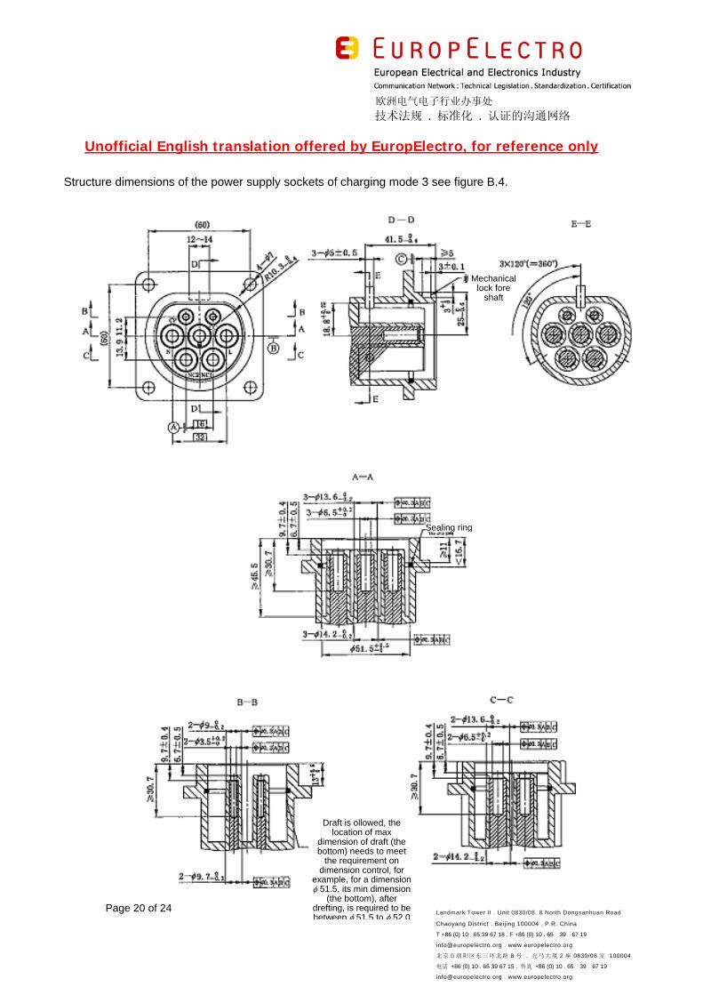
Structure dimensions of the power supply sockets of charging mode 3 see figure B.4.
Mechanical lock fore
shaft
Sealing ring
Draft is ollowed, the location of max
dimension of draft (the bottom) needs to meet
the requirement on dimension control, for
example, for a dimension 51.5, its min dimension
(the bottom), after drefting, is required to be between 51.5 to 52.0
欧洲电气电子行业办事处
技术法规 . 标准化 . 认证的沟通网络
Unofficial English translation offered by EuropElectro, for reference only
Page 21 of 24 Landmark Tower II . Unit 0830/08. 8 North Dongsanhuan Road
Chaoyang District . Beijing 100004 . P.R. China
T +86 (0) 10 . 65 39 67 18 . F +86 (0) 10 . 65 39 67 19
[email protected] . www.europelectro.org
北京市朝阳区东三环北路 8 号 . 亮马大厦 2 座 0830/08 室 100004
电话 +86 (0) 10 . 65 39 67 15 . 传真 +86 (0) 10 . 65 39 67 19
[email protected] . www.europelectro.org
Figure B.4 Structure dimensions of the power supply sockets of charging mode 3
Appendix C
(Informative)
Examples for installation dimensions of the vehicle socket and the power supply sockets of charging
mode 3
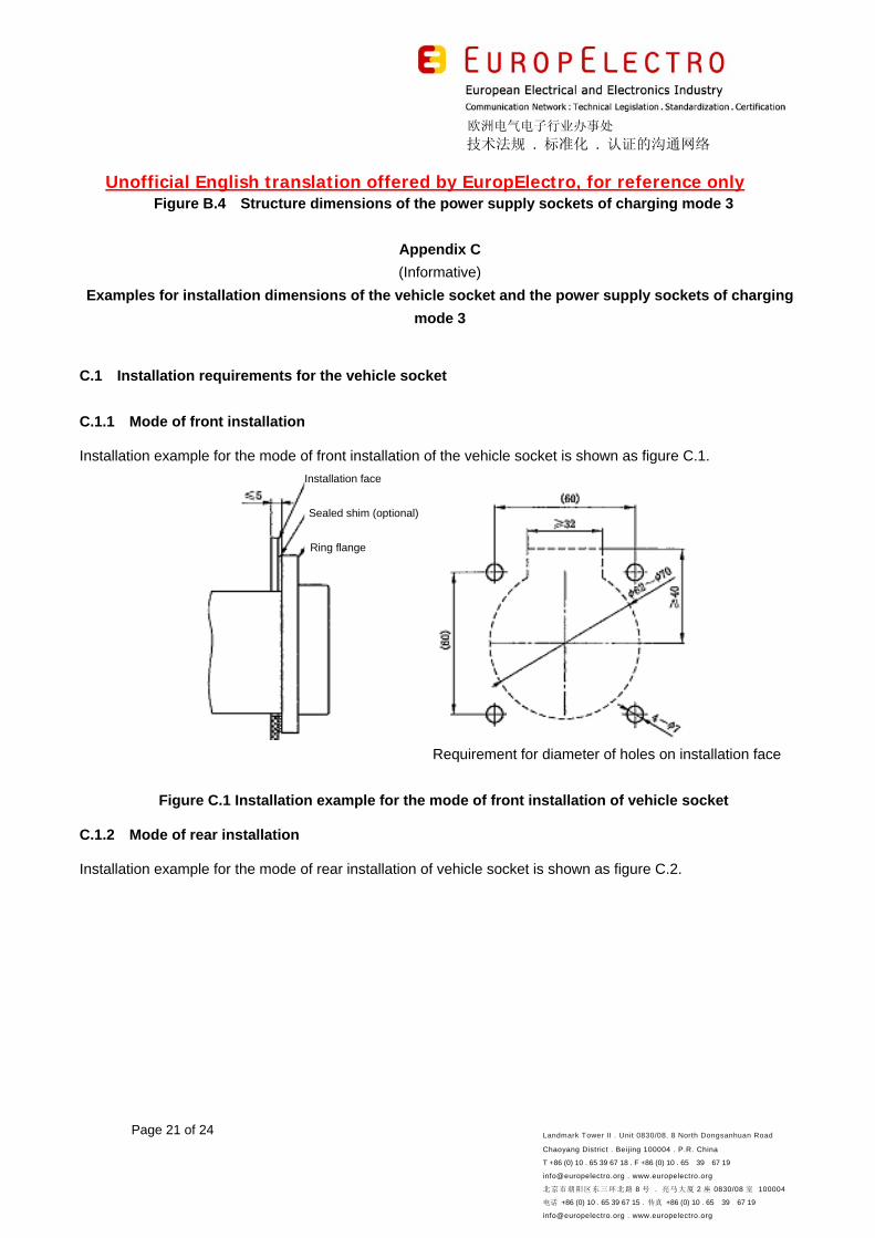
C.1 Installation requirements for the vehicle socket
C.1.1 Mode of front installation
Installation example for the mode of front installation of the vehicle socket is shown as figure C.1.
Requirement for diameter of holes on installation face
Figure C.1 Installation example for the mode of front installation of vehicle socket
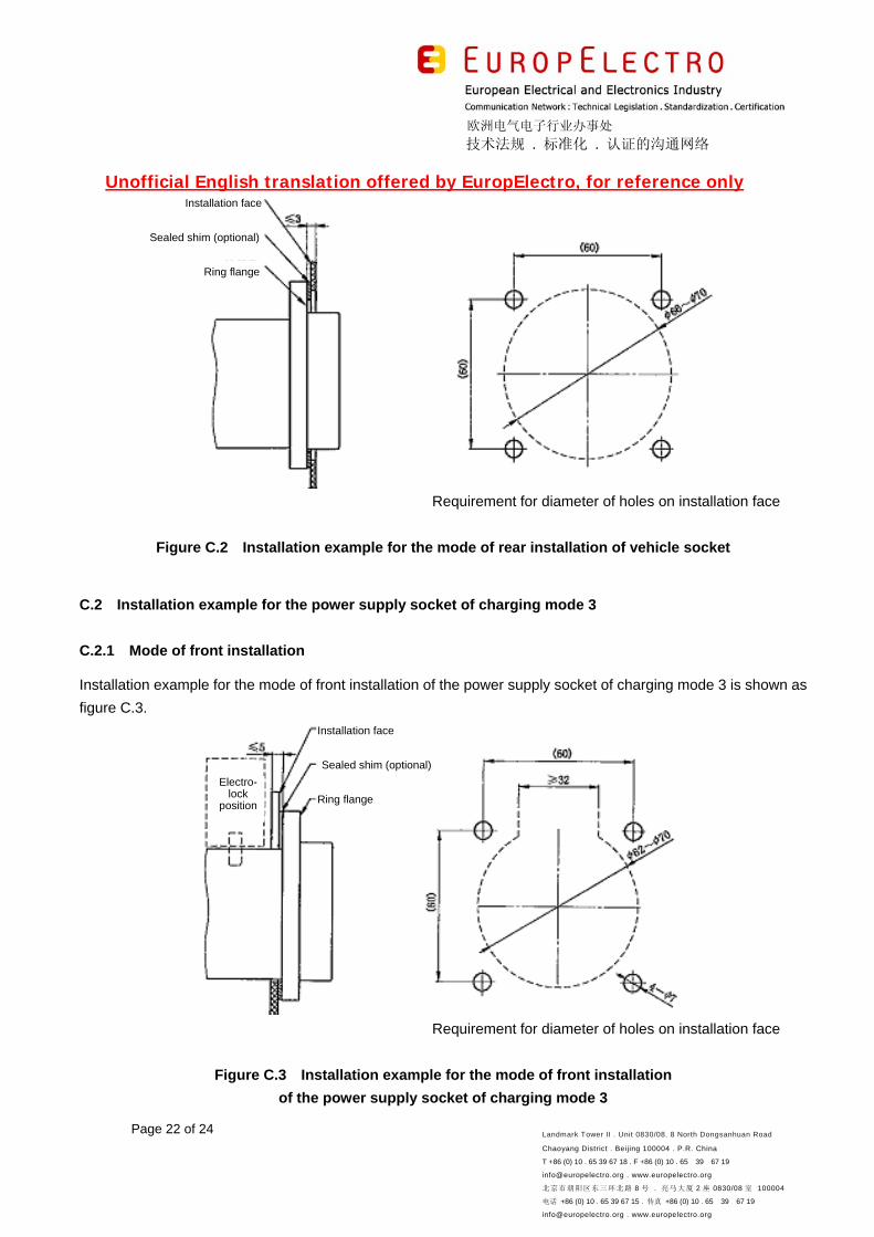
C.1.2 Mode of rear installation
Installation example for the mode of rear installation of vehicle socket is shown as figure C.2.
Installation face
Sealed shim (optional)
Ring flange
欧洲电气电子行业办事处
技术法规 . 标准化 . 认证的沟通网络
Unofficial English translation offered by EuropElectro, for reference only
Page 22 of 24 Landmark Tower II . Unit 0830/08. 8 North Dongsanhuan Road
Chaoyang District . Beijing 100004 . P.R. China
T +86 (0) 10 . 65 39 67 18 . F +86 (0) 10 . 65 39 67 19
[email protected] . www.europelectro.org
北京市朝阳区东三环北路 8 号 . 亮马大厦 2 座 0830/08 室 100004
电话 +86 (0) 10 . 65 39 67 15 . 传真 +86 (0) 10 . 65 39 67 19
[email protected] . www.europelectro.org
Requirement for diameter of holes on installation face
Figure C.2 Installation example for the mode of rear installation of vehicle socket
C.2 Installation example for the power supply socket of charging mode 3
C.2.1 Mode of front installation
Installation example for the mode of front installation of the power supply socket of charging mode 3 is shown as
figure C.3.
Requirement for diameter of holes on installation face
Figure C.3 Installation example for the mode of front installation
of the power supply socket of charging mode 3
Installation face
Sealed shim (optional)
Ring flange
Electro-lock
position
Installation face
Sealed shim (optional)
Ring flange
欧洲电气电子行业办事处
技术法规 . 标准化 . 认证的沟通网络
Unofficial English translation offered by EuropElectro, for reference only
Page 23 of 24 Landmark Tower II . Unit 0830/08. 8 North Dongsanhuan Road
Chaoyang District . Beijing 100004 . P.R. China
T +86 (0) 10 . 65 39 67 18 . F +86 (0) 10 . 65 39 67 19
[email protected] . www.europelectro.org
北京市朝阳区东三环北路 8 号 . 亮马大厦 2 座 0830/08 室 100004
电话 +86 (0) 10 . 65 39 67 15 . 传真 +86 (0) 10 . 65 39 67 19
[email protected] . www.europelectro.org
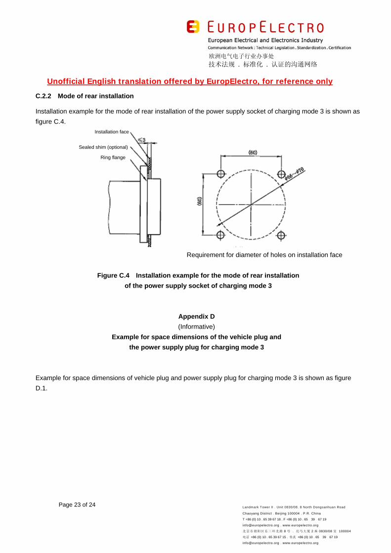
C.2.2 Mode of rear installation
Installation example for the mode of rear installation of the power supply socket of charging mode 3 is shown as
figure C.4.
Requirement for diameter of holes on installation face
Figure C.4 Installation example for the mode of rear installation
of the power supply socket of charging mode 3
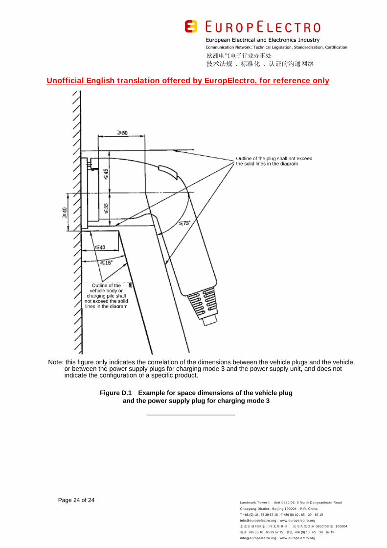
Appendix D
(Informative)
Example for space dimensions of the vehicle plug and
the power supply plug for charging mode 3
Example for space dimensions of vehicle plug and power supply plug for charging mode 3 is shown as figure
D.1.
Installation face
Sealed shim (optional)
Ring flange
欧洲电气电子行业办事处
技术法规 . 标准化 . 认证的沟通网络
Unofficial English translation offered by EuropElectro, for reference only
Page 24 of 24 Landmark Tower II . Unit 0830/08. 8 North Dongsanhuan Road
Chaoyang District . Beijing 100004 . P.R. China
T +86 (0) 10 . 65 39 67 18 . F +86 (0) 10 . 65 39 67 19
[email protected] . www.europelectro.org
北京市朝阳区东三环北路 8 号 . 亮马大厦 2 座 0830/08 室 100004
电话 +86 (0) 10 . 65 39 67 15 . 传真 +86 (0) 10 . 65 39 67 19
[email protected] . www.europelectro.org
Note: this figure only indicates the correlation of the dimensions between the vehicle plugs and the vehicle, or between the power supply plugs for charging mode 3 and the power supply unit, and does not indicate the configuration of a specific product.
Figure D.1 Example for space dimensions of the vehicle plug
and the power supply plug for charging mode 3
Outline of the plug shall not exceed the solid lines in the diagram
Outline of the vehicle body or
charging pile shall not exceed the solid lines in the diagram