Embed Size (px)
Citation preview

NML High Energy Beam Absorbers and Dump
29‐August‐2011
Beams‐doc‐3928

NML Beam AbsorbersOutlineOutline
• System Overviewy
• Absorber
• Design and AnalysisDesign and Analysis
• Assembly
• Dump Shielding• Dump Shielding
• Design
• Installation• Installation
• Summary and Status
2

System Overview
• Dump concept, configuration and radiation design by Church
and Rakhno
• Dump houses 2 water‐cooled absorbers
• Each absorber contains two independent cooling loops
• Each circuit accepts 30gpm flow rate• Each circuit accepts 30gpm flow rate
• Single RAW skid can feed multiple cooling circuitsSingle RAW skid can feed multiple cooling circuits
simultaneously
3

System Overview
4
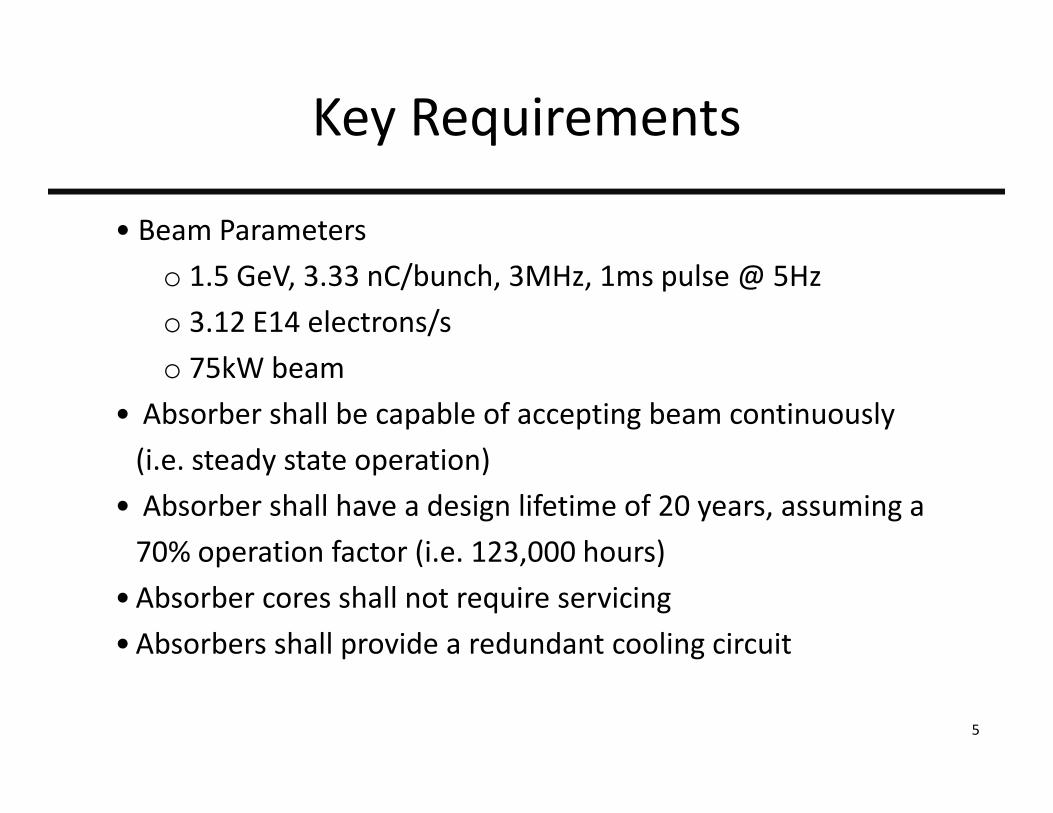
Key Requirements
• Beam Parameters
o 1.5 GeV, 3.33 nC/bunch, 3MHz, 1ms pulse @ 5Hz
o 3.12 E14 electrons/s
o 75kW beam
• Absorber shall be capable of accepting beam continuously
(i e steady state operation)(i.e. steady state operation)
• Absorber shall have a design lifetime of 20 years, assuming a
70% operation factor (i.e. 123,000 hours)70% operation factor (i.e. 123,000 hours)
• Absorber cores shall not require servicing
•Absorbers shall provide a redundant cooling circuit
5

Absorber Core Configuration
0.5m
1.85m
0.5m
6

Absorber Location

NML Beam AbsorbersOutlineOutline
• System Overviewy
• Absorber
• Design and AnalysisDesign and Analysis
• Assembly
• Dump Shielding• Dump Shielding
• Design
• Installation• Installation
• Summary and Status
8

Absorber Core Configuration
W t li i
Al
Water cooling in integral channels
AlGraphite
Al
Cu/Steel
9

Graphite/Aluminum Contact ArchitectureContact Architecture
i i i lPrimary Circuit Outlet
Redundant Circuit Outlet
hitFastener‐preloaded contact: top and bottomgraphite top and bottom
No contact on sides
Primary Circuit Inlet
R d d t Ci it I l tRedundant Circuit Inlet
10

Thermal Analysis Approach
• Step 1: Process MARS results in Excel
o Tabulate X, Y, Z and heat generation for each MARS element
• Step 2: Generate mechanical FEA models in NX/Ansys
o Two meshes are used:
• System Model: assess global effects
• Axial Section Model: assess localized heating in graphite
o Tabulate FEA mesh nodal and element XYZ locationso Tabulate FEA mesh nodal and element XYZ locations
• Step 3: Interpolate MARS results onto FEA mesh in Matlab
o Use MARS radiation damage estimates to assign material properties
o Map heat generation results from MARS mesh onto arbitrary FEA mesh
o Calculate heat generation at each FEA element
o Generate Ansys text input using BFE/HGENy p g
• Step 4: Run Ansys to recover temperatures11

MARS Model: (I. Rakhno)
Al CuH2OC
y
x
y
zx z
12

MARS ResultsHeat Generation (W/m3) linear color scaleHeat Generation (W/m3): linear color scale
Al H2OC Cu/Steel
y
z
Max: 1.32E8 W/m3 @ Z=.35m13
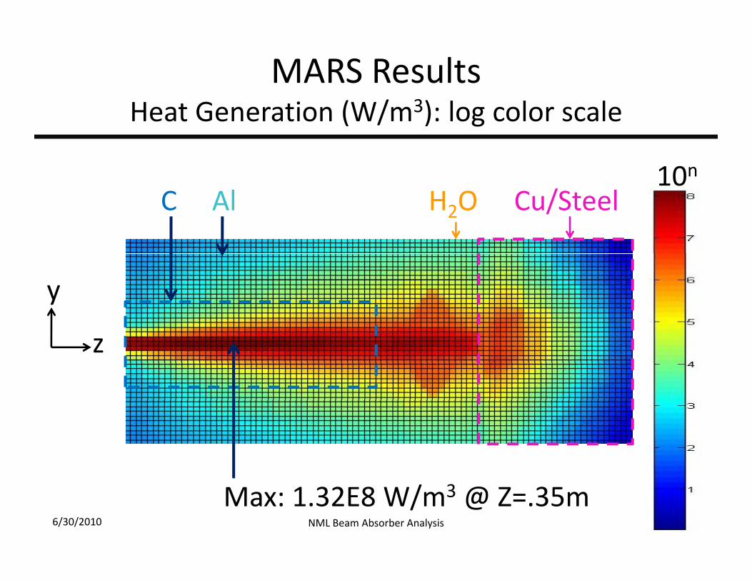
MARS ResultsHeat Generation (W/m3) log color scaleHeat Generation (W/m3): log color scale
10nAl Cu/SteelH2OC
10
y
z
Max: 1.32E8 W/m3 @ Z=.35m6/30/2010 NML Beam Absorber Analysis

Steady State Analyses
• The steady state thermal analyses neglect the pulsed nature of the energyThe steady state thermal analyses neglect the pulsed nature of the energy
deposition, and assume constant and continuous beam power
• We use two sets of graphite properties:
B i i f Lif (BOL) hi i d d d b di i• Beginning of Life (BOL) – graphite properties not degraded by radiation
damage (but still fully temperature dependant)
• End of Life (EOL) – graphite damage categorized in bins, corresponding
degraded material properties mapped onto the FEA mesh
• We further use two sets of beam conditions
• Centered beam – the original, intuitive design conceptCentered beam the original, intuitive design concept
• Off‐center beam – implemented to distribute graphite damage and
prevent catastrophic failure
I l th t ff t b t EOL• In general, the worst cases are off‐center beams at EOL
15
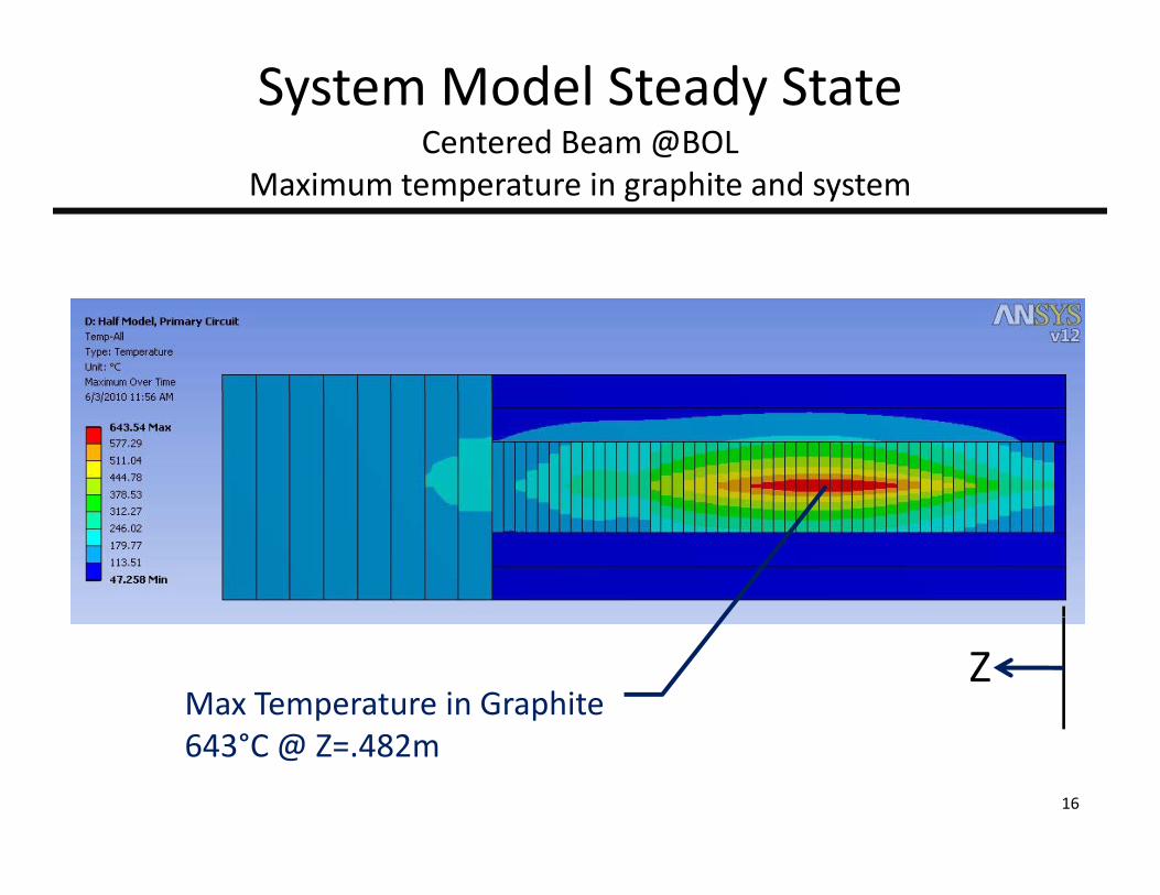
System Model Steady StateCentered Beam @BOL
Maximum temperature in graphite and system
Max Temperature in GraphiteZ
643°C @ Z=.482m
16

Radiation Effects: Graphite Thermal Conductivity ReductionGraphite Thermal Conductivity Reduction
Example data
6/30/2010 17
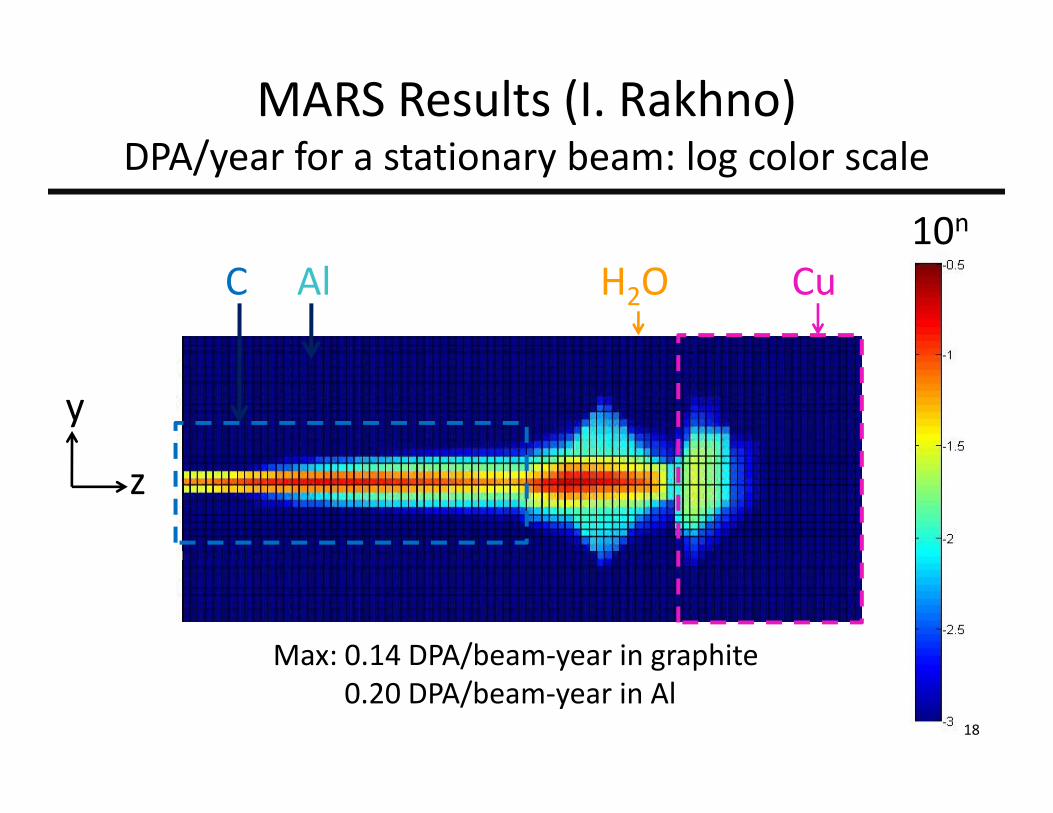
MARS Results (I. Rakhno) DPA/year for a stationary beam log color scaleDPA/year for a stationary beam: log color scale
10n
Al CuH2OC
y
z
Max: 0.14 DPA/beam‐year in graphiteMax: 0.14 DPA/beam year in graphite0.20 DPA/beam‐year in Al
18

Cumulative Damage20years 70% uptime full beam power20years, 70% uptime, full beam power
Di ib d bDistributed beamMaximum damage = 0.22 dpaZ Z
Stationary beam:Max damage = 2 8 dpaMax damage 2.8 dpa
Maroon area exceeds 0.25 dpa damage threshold

Radiation Effects: Modeled k Reduction FactorModeled k Reduction Factor
6/30/2010 20

Mapping of k Reductionat EOL on Graphite Coreat EOL on Graphite Core
Migrating Beam
Material 205Damage> 02 dpaDamage>.02 dpa
Material 204.01< Damage <.02 dpaZ Z.01 Damage .02 dpa
Material 203
Z Z
Material 203.001< Damage <.01 dpa
M i l 202Material 202.0001< Damage <.001 dpa
21

System Model Steady StateCentered Beam @EOL
Maximum temperature in graphite and system
Max Temperature in Graphite = 1703°C Z
(compare to 643°C @BOL)
22

Absorber Mechanical Design
•Based on the results and recommendations of the thermal• Based on the results and recommendations of the thermal
analysis, a detailed mechanical design was completed
23

Absorber Mechanical Design
24
Absorber Mechanical Design
•Key design features• Key design features
• Contact pressure on graphite is maintained by large‐
deflection Belleville washers
• Cooling channels are machined into aluminum plates
• Transition from aluminum cooling plates to stainless piping
is done using roll bonded transition pieces
•Galvanic corrosion managed by redundant seal features,
minimizing free area of stainless
25
NML Beam AbsorbersOutlineOutline
• System Overviewy
• Absorber
• Design and AnalysisDesign and Analysis
• Assembly
• Dump Shielding• Dump Shielding
• Design
• Installation• Installation
• Summary and Status
26

Component‐Level Assembly and Test
M h ff t t i t ti l l bli li d•Much effort was put into meticulously assembling, sealing, and
testing the individual cooling plates
27

Component‐Level Assembly and Test
28

Assembly and Test
•Cooling plates were then assembled and interconnected via
1.5”‐Schedule 40 stainless interconnect lines
29

Assembly and Test
C l t d l bi• Completed plumbing
circuits were then
hydrostatically andhydrostatically and
pneumatically tested
to ensure a leak‐tight g
system
30

Assembly and Test
• In the final step ofIn the final step of
absorber assembly,
a helium‐filled
enclosure will be
constructed around
the absorber cores.
31

NML Beam AbsorbersOutlineOutline
• System Overviewy
• Absorber
• Design and AnalysisDesign and Analysis
• Assembly
• Dump Shielding• Dump Shielding
• Design
• Installation• Installation
• Summary and Status
32

Dump Shielding Design
•The dump shielding was specified by the Church/Rakhno• The dump shielding was specified by the Church/Rakhno
radiation design
• The shielding around the absorbers is 24’ X 20’ X 24’
• ~570 tons concrete
• ~620 tons steel
•Designed following established best‐practices
• seams, gaps carefully managed
33
Dump Installation Sequence
34

NML Beam AbsorbersOutlineOutline
• System Overviewy
• Absorber
• Design and AnalysisDesign and Analysis
• Assembly
• Dump Shielding• Dump Shielding
• Design
• Installation• Installation
• Summary and Status
35

Dump Shielding Installation
•The vast majority of the steel was obtained from the railheadThe vast majority of the steel was obtained from the railhead
• Steel was measured, labeled, and cut to a common length
36

Dump Shielding Installation
37
Dump Shielding Installation
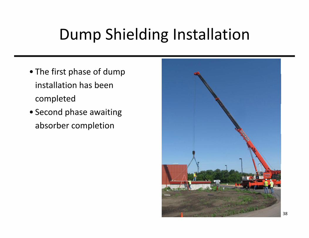
•The first phase of dumpThe first phase of dump
installation has been
completed
• Second phase awaiting
absorber completion
38

Dump Shielding Installation
39

NML Beam AbsorbersOutlineOutline
• System Overviewy
• Absorber
• Design and AnalysisDesign and Analysis
• Assembly
• Dump Shielding• Dump Shielding
• Design
• Installation• Installation
• Summary and Status
40

Status
•The assembly of the individual absorbers is nearly complete• The assembly of the individual absorbers is nearly complete
•After the helium enclosures are welded and tested, we will ,
install the absorbers in the dump
•Task completion this fall
41