Embed Size (px)
Citation preview
VDV-recommandation 301-1 01/2014
Internet Protocol based Integrated On-Board Information System IBIS-IP
Part 1: System architecture
Gesamtbearbeitung
Overall editing:
Expert committee for Telematics and Information Systems ATI Sub-committee for Communications and Information Systems UA-KIS
Contributors:
Dipl.-Ing. Dirk Weisser, Init, Karlsruhe Dr. Torsten Franke, IVU, Aachen Dr. Holger Bandelin, Scheidt & Bachmann, Mönchengladbach Dipl.-Ing. Berthold Radermacher, VDV, Cologne Dipl.-Ing. Andreas Wehrmann, VDV, Cologne Dipl.-Ing. ETH Walter Meier-Leu, we, Schaffhausen Translation was supported by:
Dipl.-Ing. (FH) Karsten Baumeister, Annax Anzeigesysteme GmbH, Brunntal Dr. Torsten Franke, IVU, Aachen Dipl.-Ing. ETH Patrik Studer, Trapeze, Neuhausen am Rheinfall, Switzerland Dipl.-Ing. Samuel Weibel, Gorba, Oberbüren, Switzerland Dipl.-Ing. Dirk Weißer, Init, Karlsruhe
The project IP-KOM-ÖV, which is the basis of this VDV recommendation,
was supported with means of the Federal Ministry for Economy and Energy
under the support code 19P10003. The responsibility for the contents of this
publication lies with the authors.

VDV 301-1 IBIS-IP Part 1: System architecture
VDV 301-1 Page 2 / 33
Table of Contents
0 Translation Disclaimer ......................................................................................... 6
1 Introduction .......................................................................................................... 6
2 Scope .................................................................................................................... 7
3 System structure .................................................................................................. 7
3.1 Basic architecture of IBIS-IP ........................................................................... 7
3.2 Terminology ................................................................................................... 9
4 IBIS-IP system architecture ................................................................................11
4.1 Determination of functional components ........................................................11
4.2 Hierarchization based on an example............................................................11
4.3 The IBIS-IP system architecture ....................................................................14
5 Groups of functionalities ....................................................................................16
5.1 Vehicle Operation Functionalities ..................................................................16
5.1.1 Device Management ...........................................................................17
5.1.2 System Documentation .......................................................................17
5.1.3 System Management ..........................................................................18
5.1.4 Diagnostics Management ....................................................................18
5.2 Driving Operation Functionalities ...................................................................18
5.2.1 Journey Information Determination ......................................................19
5.2.2 Network Locating.................................................................................19
5.2.3 Variance Comparison ..........................................................................19
5.2.4 Forecast ..............................................................................................19
5.2.5 Driving Operation Recording ...............................................................20
5.2.6 Navigation ...........................................................................................20
5.2.7 Route Control ......................................................................................20
5.3 Customer Communication Functionalities .....................................................20
5.3.1 Customer Information Determination ...................................................20
5.3.2 Passenger Display ..............................................................................21
5.3.3 Passenger Announcement ..................................................................21
5.3.4 Customer Device Communication .......................................................21
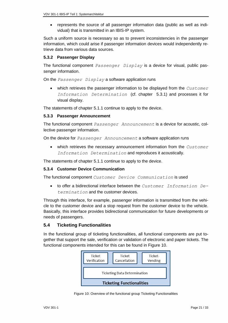
5.4 Ticketing Functionalities ................................................................................21
5.4.1 Ticketing Data Determination ..............................................................22
5.4.2 Ticket Verification ................................................................................22
5.4.3 Ticket Cancellation ..............................................................................22

VDV 301-1 IBIS-IP Part 1: System architecture
VDV 301-1 Page 3 / 33
5.4.4 Ticket Vending ....................................................................................22
5.5 Basic Functionalities ......................................................................................22
5.5.1 HF-IP Network Interface ......................................................................23
5.5.2 Mass Data Storage ..............................................................................23
5.5.3 Time Determination .............................................................................23
5.5.4 Passenger Counting ............................................................................23
5.5.5 Vehicle Interfaces ................................................................................23
5.5.6 Physical Locating ................................................................................23
5.5.7 Route Control Interface .......................................................................23
5.5.8 Coupling Interface ...............................................................................24
5.5.9 Audio Interface ....................................................................................24
5.5.10 Video Interface ....................................................................................24
5.6 Back Office Communication Functionalities ...................................................24
5.6.1 Data Import/Export ..............................................................................24
5.6.2 AVL Communication ............................................................................24
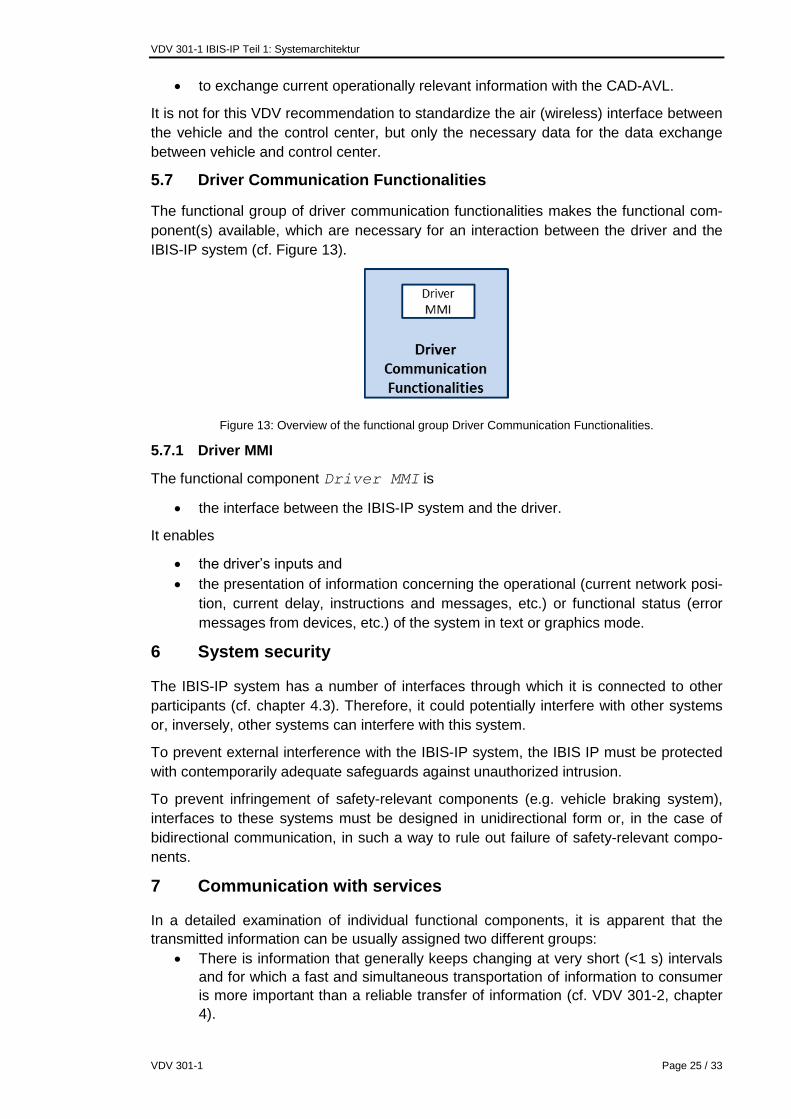
5.7 Driver Communication Functionalities ...........................................................25
5.7.1 Driver MMI...........................................................................................25
6 System security ...................................................................................................25
7 Communication with services ............................................................................25
7.1 Structuring the information content ................................................................26
8 Terminology .........................................................................................................26
9 Abbreviations ......................................................................................................32
References ..................................................................................................................33

VDV 301-1 IBIS-IP Part 1: System architecture
VDV 301-1 Page 4 / 33
Foreword
On the initiative of Verband Deutscher Verkehrsunternehmen (the Association of Ger-
man Transport Companies – VDV) and funded by the Federal Ministry of Economics,
the research and standardization project Internet Protokoll basierte Kommunikations-
dienste im öffentlichen Verkehr (IP-KOM-ÖV) [Internet Protocol-based Communications
services in Public Transport] began in September 2010.
The project is supported by 14 partners belonging to industry, universities and public
transport companies. It is intended to develop sophisticated communication concepts for
comprehensive and continuous passenger information.
Nowadays, comprehensive passenger information is a key factor of competition in pub-
lic transport, not only when compared to other transport companies but also in compari-
son with individual transport.
Even today it is common to see that transport companies convey information to their
passengers not only about the planned trips, but also provide real-time information like
current delays, events or destination changes. On the one hand, such information is
provided through public indicator systems or through announcements in vehicles or at
stops to people present there. On the other hand, such information can be queried indi-
vidually by means of specific applications or websites by users.
However, until now it is not possible to provide passengers in public transport with in-
formation relevant to their specific journey, i.e. to guide the passengers in the quickest
way to their destination with the help of public transport even in the event of an interrup-
tion.
In this respect, the widely popular smartphones and tablets offer many and varied pos-
sibilities and find a high user acceptance. In this, the transmission of information is
based on IP, and should preferably take place between a centrally located data server
and the customer device. In case the central data server is not reachable or, the vehicle
is not connected to it, communication should also be possible directly between the cus-
tomer device and the vehicle.
Therefore, the research and standardization project IP-KOM-ÖV is working on three
main areas (cf. Figure 1).

VDV 301-1 Translation DisclaimerIBIS-IP Part 1: System architecture
VDV 301-1 Page 5 / 33
Figure 1: Environment and main focus in the IP-KOM-ÖV project
The first focus (green box in Figure 1) is the specification of a high-performance IP-
based communications protocol in the vehicle (IBIS-IP). For one, the aim is to meet the
growing needs of the in-vehicle passenger information and communication. For this
purpose, the IBIS Wagenbus of the VDV 300 (cf. [1]), developed during the eighties, is
converted into a sophisticated Ethernet information architecture. On the other hand, it
deals with the definition of an IP-based interface for the transmission of information from
the vehicle to the mobile customer device. The present document is the outcome of this
part of the research project.
The second focus (red box in Figure 1) is to define the necessary interfaces in order to
cater to future applications for individual passenger information using mobile devices of
passengers (smartphones, Tablet PC, etc.) through standardization. For this purpose, in
the first step, the needs of passengers for specific details were determined. In the sec-
ond step, uniform interfaces between the real-time communication and information plat-
form (Echtzeit- Kommunikations- und Auskunftsplattform; cf. EKAP third focus) and the
mobile customer devices or between the EKAP and background systems were devel-
oped. Here, exclusively the data modeling and architectures were investigated and
specified. The development of an application for mobile devices was specifically not in-
tended and was only implemented for testing in the simplest form. The results of this
part of the research project are documented in VDV 430.
The third focus (blue box in Figure 1) is to define and create an EKAP. The EKAP bun-
dles information from ITCS and other information systems and provides a wealth of in-
formation over suitable interfaces to applications on the customer devices in a standard-
ized form. This platform enables developers of apps to dynamically provide customers
with individual messages about interruptions. The results of this part of the research
project are also documented in VDV 431.
In addition, the practical feasibility of this new standard is verified in lab and field tests.

VDV 301-1 IBIS-IP Part 1: System architecture
VDV 301-1 Page 6 / 33
0 Translation Disclaimer
This document is an English translation of the German document “Internetprotokoll ba-
siertes integriertes Bordinformationssystem IBIS-IP, Teil 1: Systemarchitektur, v1.0” re-
leased in January 2014. It is provided for convenience only and has no legal effect.
The translation of this document was done with the greatest possible accuracy. In case
of any inconsistency the German original document applies.
1 Introduction
The IBIS vehicle bus standard according to the document VDV 300 represents, on the
one hand, one of the most successful and longstanding standards of the Association of
German Transport Companies (VDV). Since the 1980s and with the technical means of
that time, it stipulated as to which datasets are used for the exchange of information be-
tween devices in the vehicle, such as on-board computers, indicators, validators, etc.
passenger counting systems and so on.
On the other hand, it is becoming increasingly clear that there is a need for a new
standard for the future. The requirements for passenger information are getting more
and more diverse increasing the demands of the performance of passenger information.
For a long time, therefore, Internet Protocol-based solutions are being used also for
passenger information within the vehicle. In the absence of a mandatory standard, a
growing number of project-specific or vendor-specific Ethernet-based solutions have
been developed in recent years. Such solutions mean high investments and integration
efforts for transport companies as well as for manufacturers and involve significant risks
for the project. Likewise, an exchange of information between the IBIS system and cus-
tomer devices of passengers is only possible through expensive individual solutions.
Today, customers traveling in different regions need different apps so as to use the in-
formation provided by the operators of public transport.
The integrated on-board information system based on Internet Protocol (IBIS-IP) repre-
sents, therefore, a powerful IP-based successor standard of the IBIS Wagenbus. Fol-
lowing the first requirements survey in the VDV release 3001, the need for a new com-
munication medium was determined on the basis of use cases. In addition, specific mi-
gration scenarios between old and new systems have been dealt with in this publication.
These findings were used as the basis for the concluded specifications in this docu-
ment.
This document is intended to assist in the process of issuing tenders for new communi-
cation systems on vehicles of public transport and thus significantly reduce costs and
risks through standard solutions. In order to keep alive this standard, the specifications
will be reviewed and updated in the annual round of the sub-committee for communica-
tions and information systems (UA-KIS). This applies to the base specification as well
as to additional services which could not be defined within the framework of the re-
search project.
In this first part, the basic architecture of IBIS-IP is defined and described as to how the
functionality of individual functions is determined and, based on that, how service-
oriented architecture shall be developed. This architecture forms the basis for a vendor-
independent architecture that is designed to ensure easy replacement of devices in the
vehicle. Furthermore, the functional components are briefly described, and security as-

VDV 301-1 IBIS-IP Part 1: System architecture
VDV 301-1 Page 7 / 33
pects of the system are summarily discussed. This document concludes with definitions
of communication architectures.
Having defined the system architecture of IBIS-IP in the first part, the second part, VDV
301-2, specifies the implementation of the technical interface based on XML structures.
2 Scope
IBIS-IP describes general rules of communication for communication between IP-based
devices of customer information in individual vehicles of public transport, and specifies
the protocol used in this communication. IBIS-IP provides particularly an IP-based suc-
cessor standard for the IBIS Wagenbus defined in VDV 300. Mapping of all IBIS
Wagenbus standard functionalities was, therefore, explicitly taken into account in the
development of IBIS-IP. The proven master / slave architecture is evolved to a service-
oriented architecture in order to enable sustainable flexible network technology ad-
vancements. On the one hand, with the definitions the focus is on a powerful communi-
cation medium and also independence from any manufacturer in regard to the periph-
erals.
The system architecture and the relevant applications presented in this document pro-
vide only for the integration of non-safety-related systems. A linking of safety-related
systems can be implemented through defined interfaces (e.g. Gateways), in which the
interface providers must be free of side-effects with respect to both systems.
3 System structure
In the following chapter, groups of functionalities are described, into which the function-
alities of the IBIS-IP system are divided, and the IBIS-IP is classified in the communica-
tive context. Finally, an introduction to the terminology is given which is used in the
course of the document.
3.1 Basic architecture of IBIS-IP
After the requirements analysis (cf. VDV release 3001), the following players that ex-
change data with an IBIS-IP system of a vehicle were identified (cf. Figure 6):
the vehicle that provides information about the vehicle to the IBIS-IP system
through interfaces (e.g. door status, odometer information),
the devices that host the IBIS-IP system on the one hand and on the other hand,
enable first of all communication with other nodes through interfaces,
route control with which the IBIS-IP system communicates for the purpose of
traffic signal priority / switch control or beacon locating,
the mobile customer device that exchanges passenger information data with the
IBIS-IP system,
ticket sale and verification devices which require information about the location
in the public transport network,
the ITCS that exchanges current real-time data with the IBIS-IP system and
other data provision and disposal systems that exchange data with the IBIS-IP
system which are not real-time data. This includes, for example, network data,
timetable data, tariff data, configuration data, log data, interruption messages
etc.

VDV 301-1 IBIS-IP Part 1: System architecture
VDV 301-1 Page 8 / 33
Such a list is, of course, open to new requirements and can be expanded in the future.
On the basis of these players, also significant functionalities can be determined which
must be available within the IBIS-IP system to operate these:
basic functionalities that enable linking the IBIS-IP system to devices and vehicle
systems through corresponding interfaces,
customer communication functionalities that combine all relevant information for
passenger information and make it available through corresponding interfaces,
ticketing functionalities that identify and provide all relevant data for ticket issuing
and verification,
driver communication functionalities that take all relevant information from the
driver and provide all relevant information to the driver,
back office communication functionalities that enable exchange of data with the
background systems and the ITCS.
In addition to this:
also driving operation functionalities that include all functions dealing with deter-
mination of one's current position in the public transport network and the result-
ing forecast and
vehicle operation functionalities that help manage the IBIS-IP system.
This results in the scheme shown in Figure 2, which represents the essential task man-
agers of vehicle system and the interfaces to external systems. The figure is detailed
further in chapter 4.3, Figure 6.
Figure 2: Classification of IBIS-IP in the communicative context.

VDV 301-1 IBIS-IP Part 1: System architecture
VDV 301-1 Page 9 / 33
Since the white box of Figure 2 deals with a number of different functions, one must
speak correctly of functional groups (cf. chapter 3.2), e.g. of the group of the basic func-
tionalities.
3.2 Terminology
In this chapter, the terms used later in the course of the document are introduced briefly.
Functional component
As part of the development of the IBIS-IP system architecture, the entire functionality of
the system was split into parts with concretely nameable functional tasks - into so-called
functional components (cf. chapter 4).
A functional component represents an encapsulation of functionality regardless of the
manner of its implementation. A functional component can be, among other things
an abstract interface to another system or device,
an application,
a service or
a device.
Since, in the present document, only part of the functional components will be specified
and implemented in the form of services or applications on devices the broader term
"functional component" is used in the description of the functionality. This also takes the
fact into account that the division into functional components was carried out with varied
elaborateness.
Functional components are highlighted by using the following
Font.
Functional Groups
A functional group combines interrelated functional components together under one
umbrella term.
Service-oriented architecture
IBIS-IP uses a service-oriented architecture. In Information Technology (IT), a ser-
vice-oriented architecture is understood to be an architectural pattern that is based on
the use of structured software modules, so-called services.
Service
A service represents a piece of software that encapsulates interrelated functionalities
and makes them available through a specified interface. Besides the functionality, the
definition of the functional scope of a service depends also on the fact which data be-
longs together or from which source the data originates.
Services run in the context of an operating system and, possibly, of a larger application
on a device. But the architecture is determined completely independent of the devices
being used, as the case may be.
The implementation of the functional component into services and the specification of
the corresponding interfaces are described in Part 2 of the present document. Also the
relation between a service and the associated functional component is explained there.

VDV 301-1 IBIS-IP Part 1: System architecture
VDV 301-1 Page 10 / 33
Operations
Services provide their functionalities through a series of operations.

VDV 301-1 IBIS-IP Part 1: System architecture
VDV 301-1 Page 11 / 33
Example 1:
The interrelationship between the device, service and operation is illustrated in Figure 3
with reference to a general case and in the example of the service SystemManage-
mentService (an implementation of the functional component System Management
in the form of a service (cf. chapter 5.1.2 and Part 2 of the present document)).
Figure 3: Classification of the terms device, service and operation.
In the example, the service "System Management Service" is running on the device "on-
board computer. This service includes operations that allow querying once the status of
the device (GetDeviceState) or the system state (GetSystemStatus). In addition, there
are operations with which one can sign up for a subscription to certain information (e.g.
SubscribeDeviceStatus, SubscribeSystemStatus) and also unsubscribe (e.g. Unsub-
scribeDeviceStatus, UnsubscribeSystemStatus).
More explanation about operations and services can be found in Part 2 of this docu-
ment.
4 IBIS-IP system architecture
4.1 Determination of functional components
Based on the requirements described in the VDV release 3001 (cf. also [2]), all func-
tional components were determined which are necessary so as to handle use cases de-
scribed therein.
Moreover, for the development of an IBIS-IP system architecture
the data flows in the different scenarios of the VDV release 3001 and
the associated calls were analysed.
This resulted in a hierarchization of functional components that also form the basis for
hierarchical service-oriented software architecture. Details on the specified services can
be found in Part 2 of the document.
The following explains the procedure for determining the hierarchical structure with an
example.
4.2 Hierarchization based on an example
The use case 6.1.1.6 "Transmission of a target text to an external indicator" of VDV re-
lease 3001 was analysed.

VDV 301-1 IBIS-IP Part 1: System architecture
VDV 301-1 Page 12 / 33
The following functional components are involved in this use case:
Driver MMI (cf. also chapter 5.7.1)
The functional component that provides the GUI (graphical user interface) to the
driver, determines all information which the driver requires and passes on all driver
inputs.
Journey Information Determination (cf. also chapter 5.2.1)
The functional component that determines the required location and time-specific in-
formation concerning the current trip, based on a setting by the driver or the control
center.
Customer Information Determination (cf. also chapter 5.3.1)
The functional component that determines the data, based on the current network
locating and information about the current trip, which is relevant to the passenger in-
formation.
Network Locating (cf. also chapter 5.2.2)
The functional component that determines the current location in the public transport
network, on the basis of local data concerning an active trip (normally, based on the
Journey Information Determination) and the Physical locating
(GPS coordinates, distance pulse counter, door criterion).
Physical Locating (cf. also chapter 5.5.6)
This refers to the functional component that provides data about the physical loca-
tion or about the devices (GPS receivers) through Vehicle interfaces (dis-
tance pulse counter, door signal).
Vehicle Interfaces (cf. also chapter 5.5.5),
The functional component that enables other services access to vehicle interfaces.
Passenger Display (cf. also chapter 5.3.2),
This refers to the functional component that handles the public visual presentation of
information for the passenger.
The obtained flow of data is shown in Figure 4.

VDV 301-1 IBIS-IP Part 1: System architecture
VDV 301-1 Page 13 / 33
Figure 4: Illustration of data flows in the use case "Transmission of a target text to an external indicator".
The data flow is in the direction of the arrows.
Using this method, the direction of data flow has been verified for a number of use cas-
es. This approach was used mainly to check if the functional components represent a
useful encapsulation, that is to say, whether always the same or at least a few different
bursts of information must be provided by the functional component in question. Conse-
quently, it was possible to produce also an orchestration for the architecture which was
necessary for the implementation of service-oriented architecture. This process is illus-
trated in Figure 5 as an example for the use case mentioned above.

VDV 301-1 IBIS-IP Part 1: System architecture
VDV 301-1 Page 14 / 33
Figure 5: Hierarchization through an arrangement of functional components according to direction of calls.
The following applies to Figure 5 and the following figures:
Functional components further below provide data to functional components fur-
ther above.
Functional components further above are, therefore, the active information users
(client role), who retrieve data from passive information providers (server role).
Functional components further below usually do not know the service of a func-
tional component that queries data.
Functional components or devices further above know the services of functional
components from which they must retrieve data.
The green arrows must be understood in the sense of "uses functionality of", e.g.
the functional component Customer Information Determination
uses a functionality of the service of the functional component Journey in-
formation determination that is provided by this service (namely, the
functionality to determine the current line / course; cf. Figure 4).
4.3 The IBIS-IP system architecture
If we conduct this analysis for other use cases involving all identified functional compo-
nents of the IBIS-IP system, the result would be an overall view of the system as shown
in Figure 6.

VDV 301-1 IBIS-IP Part 1: System architecture
VDV 301-1 Page 15 / 33
Figure 6: Hierarchy of the groups of functionalities and functional components in the IBIS-IP system.

VDV 301-1 IBIS-IP Teil 1: Systemarchitektur
VDV 301-1 Page 16 / 33
The medium blue rectangle represents the IBIS-IP system and the white boxes are the
functional components. The light blue rectangles represent groups of functionalities.
Oval elements outside the IBIS-IP system are participants with whom the IBIS-IP sys-
tem communicates through interfaces (not necessarily IP interfaces). They can be de-
vices, organizational units or individuals.
In this figure, another, coupled vehicle appears in addition to the players mentioned in
chapter 3.1. Since in the IBIS-IP architecture, each vehicle by itself represents a closed
system, this is the link of another IBIS-IP system, for which corresponding interfaces
need to be provided.
5 Groups of functionalities
This chapter explains the functionality of the functional components. The description fol-
lows the functional grouping of the functional components, which has already been used
in chapter 3.1, i.e. into functionalities of the
vehicle operation,
driving operation,
customer communication,
ticketing,
back office communication,
driver communication and
basic functionalities.
A detailed technical description, including the transition into services, is given in Part 2
of this document.
5.1 Vehicle Operation Functionalities
The vehicle operation functionalities include functional components which are intended
to manage the operation of all devices and services that belong to an IBIS-IP system.
Specifically, they are functional components such as
Device Management
System Documentation
System Management and
Diagnostics Management.
An overview of the functional components that belong to the functional group is given
Figure 7.

VDV 301-1 IBIS-IP Teil 1: Systemarchitektur
VDV 301-1 Page 17 / 33
Figure 7: Overview of the functional group Vehicle Operation Functionalities
The functional components of the vehicle operation functionalities control particularly the
system startup and are used to monitor the overall system at runtime. Details on the im-
plementation of system startup and system monitoring can be found in Part 2 of this
document.
5.1.1 Device Management
The functional component Device Management is distinguished from other func-
tional components by the fact
that it is present on every device of an IBIS-IP system and
that it always starts automatically.
Through the Device Management of a device
other services on a device are launched or stopped;
information on the statuses of all services on the device is provided and
information about the status of the device is provided;
error messages are held out for diagnostics management.
This is generally done through communication with the functional component System
Management (cf. chapter 5.1.3). Every device that has to be controlled and monitored
in IBIS-IP by the System Management must possess a Device Management.
5.1.2 System Documentation
The functional component System Documentation is intended for
collecting,
logging and
publishing
of
System configuration data
Status messages and error messages related to the system status.
In particular, the reference configuration of an IBIS-IP system can be queried through
the System Documentation.

VDV 301-1 IBIS-IP Teil 1: Systemarchitektur
VDV 301-1 Page 18 / 33
5.1.3 System Management
The functional component System Management
controls and
monitors
the IBIS-IP system
at the start-up,
during the operation and
on shutdown.
In the event of a malfunction of a service, appropriate action (by restarting or stopping
the faulty service, launching an alternative service, notification of other services) can be
initiated through the System Management. In addition, the System Management
allows the service personnel to intervene through a suitable interface for the Diagnos-
tics Management (cf. chapter 5.1.4) by monitoring the current IBIS-IP system or by
controlling.
5.1.4 Diagnostics Management
The functional component Diagnostics Management
represents the interface between the workshop personnel and the IBIS-IP sys-
tem.
For this purpose, it provides a web interface through which
o the status of all devices and
o the status of all services are displayed in human readable form and
o services can be launched or stopped manually.
This is done through an interface between the Diagnostics Management and the
System Management.
Furthermore,
the configuration of the IBIS-IP system and of individual devices can be
changed.
This is done through an interface to the System Documentation or to the individu-
al devices.
In addition, any available optional device or service-specific service web interface can
be accessed through the Diagnostics Management.
5.2 Driving Operation Functionalities
The driving operation functionalities include within the IBIS-IP system the functional
components that are significant for the execution of public transport operations.
Thus, in this functional group, the information necessary for indicators, operational con-
trol systems and ticketing is determined based on timetable data, depending on time
and space related locating in the public transport network, and made available within the
services availing the IBIS IP. An overview of the functional components belonging to the
functional group is given in Figure 8.

VDV 301-1 IBIS-IP Teil 1: Systemarchitektur
VDV 301-1 Page 19 / 33
Figure 8: Overview of the functional group Driving Operation Functionalities.
5.2.1 Journey Information Determination
The functional component Journey Information Determination
determines all relevant reference data based on a trip identification concerning
this trip
and it can optionally
pass on to the querying service (e.g. when data is requested through the
Driver MMI for information only) or
use as a current system-wide trip (e.g. if a new trip is set through the Driver
MMI or the ITCS).
5.2.2 Network Locating
The functional component Network Locating is intended
for determining the current position in the network.
Normally, this is done on the basis of
reference data of the Journey Information Determination (cf.
chapter 5.2.1) and
realtime information of the Physical Locating (cf. chapter 5.5.6).
5.2.3 Variance Comparison
The functional component Variance Comparison is used;
to determine the timetable status (earliness, delay) of a vehicle
based on the comparison of the actual position of a vehicle with respect to the expected
position of the vehicle according to the timetable.
5.2.4 Forecast
The functional component Forecast is used
to determine the expected arrival and departure times at the subsequent stops.
This is done in the simplest case, taking into account the reference data of the trip, and
considering the current timetable status. The quality of this forecast depends on how
well the target reference can reflect the real situation. It is not for this VDV recommen-

VDV 301-1 IBIS-IP Teil 1: Systemarchitektur
VDV 301-1 Page 20 / 33
dation to define how the forecast can be optimally determined. This must be defined
project-specifically.
5.2.5 Driving Operation Recording
The functional component Driving Operation Recording is used
to record relevant operational events resulting from driving operation and to link
with current network and position information.
For example, by this a passenger counting dataset can be linked to the associated stop.
It is not for this VDV recommendation to define the frequency at which this data needs
to be recorded. This must be defined project-specifically.
5.2.6 Navigation
The functional component Navigation is used
to determine navigation information on the current trip.
This is done taking into consideration the trip distance information about the current trip,
which is determined either on the vehicle or at the control center. It is not for this VDV
recommendation to define the quality with which this data needs to be determined. This
must be defined project-specifically.
5.2.7 Route Control
The functional component Route Control is used
to determine information on required route control actions (traffic signal priority,
switch control, etc.).
This is generally based on the trip distance data of the current trip and the information
about the current location. It is not for this VDV recommendation to define with which
local accuracy it needs to be done. This must be defined project-specifically.
5.3 Customer Communication Functionalities
The functional components of the functional group of customer communication function-
alities are used for either public passenger information (display, announcement) or they
allow a passenger to retrieve individual information (e.g. possibilities of interchanging) or
to transmit the same (e.g. a stop request). The interface itself is specified in the docu-
ment VDV 431-2. In Figure 9 there is an overview of the functional components summa-
rized in the functional group.
Figure 9: Overview of the functional group Customer Communication Functionalities.
5.3.1 Customer Information Determination
The functional component Customer Information Determination
determines all information relevant to passenger information and
VDV 301-1 IBIS-IP Teil 1: Systemarchitektur
VDV 301-1 Page 21 / 33
represents the source of all passenger information data (public as well as indi-
vidual) that is transmitted in an IBIS-IP system.
Such a uniform source is necessary so as to prevent inconsistencies in the passenger
information, which could arise if passenger information devices would independently re-
trieve data from various data sources.
5.3.2 Passenger Display
The functional component Passenger Display is a device for visual, public pas-
senger information.
On the Passenger Display a software application runs
which retrieves the passenger information to be displayed from the Customer
Information Determination (cf. chapter 5.3.1) and processes it for
visual display.
The statements of chapter 5.1.1 continue to apply to the device.
5.3.3 Passenger Announcement
The functional component Passenger Announcement is a device for acoustic, col-
lective passenger information.
On the device for Passenger Announcement a software application runs
which retrieves the necessary announcement information from the Customer
Information Determination and reproduces it acoustically.
The statements of chapter 5.1.1 continue to apply to the device.
5.3.4 Customer Device Communication
The functional component Customer Device Communication is used
to offer a bidirectional interface between the Customer Information De-
termination and the customer devices.
Through this interface, for example, passenger information is transmitted from the vehi-
cle to the customer device and a stop request from the customer device to the vehicle.
Basically, this interface provides bidirectional communication for future developments or
needs of passengers.
5.4 Ticketing Functionalities
In the functional group of ticketing functionalities, all functional components are put to-
gether that support the sale, verification or validation of electronic and paper tickets. The
functional components intended for this can be found in Figure 10.
Figure 10: Overview of the functional group Ticketing Functionalities

VDV 301-1 IBIS-IP Teil 1: Systemarchitektur
VDV 301-1 Page 22 / 33
5.4.1 Ticketing Data Determination
The functional component Ticketing Data Determination determines all in-
formation relevant to ticketing, taking into account the current location in the network
and the tariff data valid in this network and makes it available to all the participants in
IBIS-IP. Furthermore, the Ticketing Data Determination is capable of verify-
ing on the basis of given data if a ticket is valid or not.
5.4.2 Ticket Verification
The functional component Ticket Verification is a device which is able to verify
the validity of a ticket on the basis of data read from the ticket including the Ticket-
ing Data Determination.
The statements of chapter 5.1.1 continue to apply to the device.
5.4.3 Ticket Cancellation
The functional component Ticket Cancellation is a device which is able to vali-
date a ticket on the basis of data delivered by the functional component Ticketing
Data Determination. In the simplest cases, this can be done by a corresponding
stamping. In more complex cases, corresponding information of the Ticketing Da-
ta Determination can be written.
The statements of the chapter 5.1.1 continue to apply to the device.
5.4.4 Ticket Vending
The functional component Ticket Vending is represented by a vending machine
and includes the following functions:
provision of a MMI for the sale of tickets.
The machine obtains the information necessary for the sale from the functional compo-
nent Ticketing Data Determination.
The statements of the chapter 5.1.1 continue to apply to the device.
5.5 Basic Functionalities
The functional group of basic functionalities includes in IBIS IP a range of functional
components that provide either an interface to peripheral devices or deliver the basic
information with less functional complexity. Figure 11 illustrates this functional group.
Figure 11: Overview of the functional group Basic Functionalities.

VDV 301-1 IBIS-IP Teil 1: Systemarchitektur
VDV 301-1 Page 23 / 33
5.5.1 HF-IP Network Interface
The functional component HF-IP Network Interface is used
to provide an interface between the IBIS-IP network and an HF network.
An HF network means analogous, digital and IP data radio systems.
5.5.2 Mass Data Storage
The functional component Mass Data Storage is used
to store, write and to read data.
This can include data of a video system as well as trip and network data that are trans-
mitted from the back office to the vehicle.
5.5.3 Time Determination
The functional component Time Determination is used
to determine the exact time and
to provide a time server for synchronizing the time between the participating de-
vices of an IBIS-IP system.
5.5.4 Passenger Counting
The functional component Passenger Counting is a device that is used
to register the number of passengers boarding and alighting the vehicle or
the percentage of vehicle occupancy and to make the information available.
The statements of the chapter 5.1.1 continue to apply to the device.
5.5.5 Vehicle Interfaces
The functional component Vehicle Interfaces is used
to provide interfaces between IBIS-IP network and information about vehicle-
internal communication systems (such as MVB, BusFMS, odometer, door sig-
nal).
For naming the functional component, the plural form was consciously chosen because
functionally and technically there can be several interfaces.
5.5.6 Physical Locating
The functional component Physical Locating is used
to determine the geographical coordinates,
to determine the distances or odometer pulses and
to determine locating-relevant information (beacon information).
5.5.7 Route Control Interface
The functional component Route Control Interface is used
to provide an interface between the IBIS-IP system and the device for route con-
trol.
Devices for route control can be, for example, analogous radio units or devices for in-
ductive message transmission.

VDV 301-1 IBIS-IP Teil 1: Systemarchitektur
VDV 301-1 Page 24 / 33
5.5.8 Coupling Interface
The functional component Coupling Interface is used
to provide a communication link between the IBIS IP systems in two or more
coupled vehicles.
It is important to note that IBIS IP treats the individual vehicles as closed networks. A
resolution of the coupling information and treatment must be handled by this interface.
5.5.9 Audio Interface
The functional component Audio Interface is used
to provide functionalities for IP based audio communication in the system.
There is of course a close connection to the announcement devices, such as a passen-
ger announcement system.
5.5.10 Video Interface
The functional component Video Interface is used
to provide functionalities for IP-based video communication in the system.
5.6 Back Office Communication Functionalities
The functional group of back office communication functionalities provides functions in
the IBIS-IP that allow an exchange of information between the vehicle and a back office
system. Here, primarily communication with the operation control center (AVL) is obvi-
ous. But also the transmission of software, firmware or data updates is ensured by the
functional components of this functional group. The functional components needed for
this can be found in Figure 12.
Figure 12: Overview of the functional group Back Office Communication Functionalities.
5.6.1 Data Import/Export
The functional component Data Import/Export is used
to exchange data between the vehicle and a back office system, such as
o Firmware updates
o Timetable data
o Ticketing data
o Diagnostics data
o Logging data and so on.
5.6.2 AVL Communication
The functional component AVL communication is used
VDV 301-1 IBIS-IP Teil 1: Systemarchitektur
VDV 301-1 Page 25 / 33
to exchange current operationally relevant information with the CAD-AVL.
It is not for this VDV recommendation to standardize the air (wireless) interface between
the vehicle and the control center, but only the necessary data for the data exchange
between vehicle and control center.
5.7 Driver Communication Functionalities
The functional group of driver communication functionalities makes the functional com-
ponent(s) available, which are necessary for an interaction between the driver and the
IBIS-IP system (cf. Figure 13).
Figure 13: Overview of the functional group Driver Communication Functionalities.
5.7.1 Driver MMI
The functional component Driver MMI is
the interface between the IBIS-IP system and the driver.
It enables
the driver’s inputs and
the presentation of information concerning the operational (current network posi-
tion, current delay, instructions and messages, etc.) or functional status (error
messages from devices, etc.) of the system in text or graphics mode.
6 System security
The IBIS-IP system has a number of interfaces through which it is connected to other
participants (cf. chapter 4.3). Therefore, it could potentially interfere with other systems
or, inversely, other systems can interfere with this system.
To prevent external interference with the IBIS-IP system, the IBIS IP must be protected
with contemporarily adequate safeguards against unauthorized intrusion.
To prevent infringement of safety-relevant components (e.g. vehicle braking system),
interfaces to these systems must be designed in unidirectional form or, in the case of
bidirectional communication, in such a way to rule out failure of safety-relevant compo-
nents.
7 Communication with services
In a detailed examination of individual functional components, it is apparent that the
transmitted information can be usually assigned two different groups:
There is information that generally keeps changing at very short (<1 s) intervals
and for which a fast and simultaneous transportation of information to consumer
is more important than a reliable transfer of information (cf. VDV 301-2, chapter
4).

VDV 301-1 IBIS-IP Teil 1: Systemarchitektur
VDV 301-1 Page 26 / 33
As against the above, there is information that changes rarely (> 1s). If it chang-
es at all, it must be ensured that all consumers are reliably made aware of this
change (cf. VDV 301-2, chapter 4).
Bearing the IP standard protocols from the OSI layer 4 in mind, we come to the conclu-
sion that for the rapidly changing information due to the simultaneous transmission to
many participants, the UDP protocol is most suitable; alternatively, the TCP protocol for
longer valid information due to the security of transmission.
By using the UDP protocol for rapidly changing information, it is ensured that this infor-
mation is distributed simultaneously to all consumers. To ensure compatibility with the
IP protocol IPv6, broadcast mechanisms must be dispensed with and, instead, UDP
multicast must be used (cf. VDV 301-2, chapter 4)).
In a more detailed examination of the tasks and communication processes with longer
valid information, it was apparent that the HTTP protocol built on top the TCP protocol
facilitates much functionality that is necessary for these processes. Therefore, the deci-
sion is to use the HTTP protocol for the transmission of reliable communication within
IBIS-IP.
Moreover, it is quite imaginable that also other IP-based communication protocols could
be used (e.g. SNTP for time synchronization or the RTP protocol for streaming of audio
and video data). However, these are not yet specified in this issue.
7.1 Structuring the information content
Since all currently established interface descriptions in the domain of public transport
(e.g. SIRI, VDV 453, VDV 454) are built on the XML format, the XML format is to be
used as well for the transmission of information between two services in IBIS-IP. This
also applies to the interface developed as part of the IP-KOM-ÖV architecture for mobile
applications (cf. VDV 431-2). In the implementation of XML-structures also the SIRI
standard [5] has been taken into consideration for the sake of homogeneity of the data
from the information systems.
8 Terminology
Term Description Audio Interface Functional component in IBIS-IP
that enables IP-based language communication between customers and driver or the control center.
AVL communication Functional component in IBIS-IP that provides communication be-tween ITCS and vehicle.
Back Office communication functions Umbrella term in IBIS-IP that sum-marizes the functional components which enable communication with background systems outside the vehicle.
Basic Functionalities Umbrella term in IBIS-IP that sum-marizes the functional components which make basic functionalities of the vehicle available.
Beacon locating Based on fixed locating points

VDV 301-1 IBIS-IP Teil 1: Systemarchitektur
VDV 301-1 Page 27 / 33
(beacons), vehicles passing the beacon can determine their current position in the network.
Client/Server Interrelated as carriers of infor-mation and receivers of information within a network.
Component From the viewpoint of the IBIS-IP system, a component is a partici-pant in the network communication.
Coupling Interface Functional component in IBIS-IP that provides an interface for con-figuration and communication when two or more vehicles are coupled.
Customer Communication Functionalities Umbrella term in IBIS-IP that sum-marizes the services which are di-rectly associated with the Custom-er Communication.
Customer Device This can be the simple mobile phones, smartphones/PDA, naviga-tion systems or Notebooks.
Customer Device Communication Functional component in IBIS-IP that handles the entire operating and information interface in the mobile customer device.
Customer Information Determination In IBIS-IP, the functional compo-nent Customer Information Deter-mination is used as a source of in-formation for all types of passenger information.
Data Import/Export Functional component in IBIS-IP that provides communication be-tween the "back office" and vehicle for the exchange of files.
Device Management Functional component in IBIS-IP that provides an interface to con-trolling and monitoring of a device.
Diagnostics Management Functional component in IBIS-IP that handles the entire operating and information interface to the personnel of the workshop.
Driver Communication Umbrella term in IBIS-IP that sum-marizes the functional components which enable interaction between driver and IBIS-IP.
Driver MMI Functional component in IBIS-IP that handles the entire operating and information interface to the driver.
Driving operation recording Functional component in IBIS-IP that assumes the task of recording data related to the driving opera-tion (e.g. drive profile data, pas-senger counting, etc.).
Ethernet Basic network technology for communication among computer networks.

VDV 301-1 IBIS-IP Teil 1: Systemarchitektur
VDV 301-1 Page 28 / 33
Forecast Functional component in IBIS-IP that determined forecasts for the arrival and departure time, includ-ing interchange connections at successive stops for the current and, as the case may be, subse-quent trip.
Functional component A functional component represents an encapsulation of functionality regardless of the method of its im-plementation. A functional compo-nent can be, among other things
an abstract interface to an-other system or device
an application
a service or
a device.
Functional groups A functional group summarizes several functionally related func-tional components into one umbrel-la term.
Functionality The functionality signifies the parts of a system that has concretely nameable functional tasks such as “Validate ticket”.
Gateway A Gateway is the linking of two mostly different networks. Such linking can be implemented merely physically but also by utilizing software technology.
HF-IP Network Interface Functional component in IBIS-IP that provides an interface between the vehicle IP network and an HF-IP network (UMTS, WLAN, GPRS and similar).
IBIS The Integrated On-board Infor-mation System is an obsolete communication standard for ex-change of passenger information (cf. [1]).
IBIS-IP Internet Protocol-based successor standard of IBIS according to VDV 300.
IBIS System A Master/Slave based network on vehicles for passenger information in the public transport system (cf. [1]).
IBIS Wagenbus Communication medium based on IBIS (cf. [1])
Journey information determination Functional component in IBIS-IP that determines the current trip or the current trip route, including all related data that is assigned to a trip or a trip route.
Mass Data Storage Functional component in IBIS-IP that assumes the task of storing

VDV 301-1 IBIS-IP Teil 1: Systemarchitektur
VDV 301-1 Page 29 / 33
and provision of files.
Master/Slave architecture Describes a special type and method of communication within a network. In this, the Master coordi-nates the communication process-es of the rest of the participants (Slaves).
Navigation Functional component in IBIS-IP that provides information to the driver for finding the route in the traffic network.
Network Locating Functional component in IBIS-IP that provides information about the current position on the trip route.
On-board computer In the age of IBIS this has been the central controlling computer (IBIS-Master). In more advanced com-munication architectures, this can also be only an MMI.
Operation Services provide their functionali-ties through a series of operations.
Orchestration Arrangement of services within a service-oriented architecture.
OSI layer Internationally standardized defini-tion of network protocols based on seven layers.
Passenger Announcement Functional component in IBIS-IP that processes acoustical infor-mation intended for the passen-gers.
Passenger counting Functional component in IBIS-IP that determines the number of boarding and alighting passengers or the percentage of vehicle occu-pancy and makes the information available.
Passenger Display Functional component in IBIS-IP that processes visual information intended for the passengers.
Physical Locating Functional component in IBIS-IP that provides trip route independ-ent information to determine the location.
Route Control Functional component in IBIS-IP that initiates route control actions, like acting on signal systems (among other things on traffic lights) depending on the current location and the reference data provided.
Route Control Interface Functional component in IBIS-IP that provides an interface to route control.
Service A service represents a piece of software application that encapsu-lates functionally associated func-

VDV 301-1 IBIS-IP Teil 1: Systemarchitektur
VDV 301-1 Page 30 / 33
tionalities and makes it available through a specified interface. Be-sides the functionality, the defini-tion of the functional range of a service also conforms as to which data belongs together or from where the data is sourced.
Service-oriented architecture This describes a system architec-ture which, independent of the communication medium, encapsu-lates information and can ex-change it between services.
Streaming The transportation of digital video or audio data over a network.
System architecture Shows the system of linking of en-tities which must be available to each other for communication.
System Documentation Functional component in IBIS-IP that stores and makes available the system configuration data.
System Management Functional component in IBIS-IP that assumes the total control of services and devices in IBIS-IP.
Ticketing Umbrella term in IBIS-IP that sum-marizes the functional components which are directly associated with the ticketing process.
Ticket Cancellation Functional component in IBIS-IP that provides an interface for ticket cancellation and ticket validation systems.
Ticket Vending Functional component in IBIS-IP that provides an interface for the ticket sale systems.
Ticket Verification Functional component in IBIS-IP that provides an interface for ticket verification systems.
Time determination Functional component in IBIS-IP that determines and provides time information.
Variance Comparison Functional component in IBIS-IP that determines the time variance between the current and planned timetable status.
Vehicle Interfaces Functional component in IBIS-IP that provides an IBIS-IP-system with non-IBIS-IP vehicle data from sources outside the IBIS-IP sys-tem.
Vehicle Operation Functionalities Functional group in IBIS-IP that summarizes the functional compo-nents which are associated with the structure and the operation of the IBIS-IP network in the vehicle.
Video Interface Functional component in IBIS-IP that enables transmission of video

VDV 301-1 IBIS-IP Teil 1: Systemarchitektur
VDV 301-1 Page 31 / 33
data based on IP in the system.

VDV 301-1 IBIS-IP Teil 1: Systemarchitektur
VDV 301-1 Page 32 / 33
9 Abbreviations
Abbreviation Description App Application primarily found on mobile devices of passengers
BMWi Bundes Ministerium für Wirtschaft und Technologie (Federal Ministry of Economics and Technology)
EKAP Echtzeitkommunikations- und -auskunftsplattform. (Real-time Communication and Information Platform) Cf. VDV 431-1.
ELA Elektroakustische-Anlage (Public Address system, PA)
HTTP Hypertext Transfer Protocol
IBIS Integrated On-board Information System
IBIS-IP Integrated On-board Information System based on Internet Pro-tocol
IBIS-IP Integrated On-board Information System based on Internet Pro-tocol
IP Internet Protocol
IP-KOM-ÖV Internet Protokoll basierte Kommunikationsdienste für den öf-fentlichen Verkehr (Internet Protocol based Communication Services for Public Transport)
IPv6 Internet Protocol according to Version 6. Its earlier version was the Version 4 (IPv4).
IT Information Technology
ITCS Intermodal Transport Control System
TSP Traffic signal priority
MMI Man-Machine Interface
OSI Open Systems Interconnection
RTP Real-time Transport Protocol
SIRI Service Interface for Real Time Information EN 15531
SOA Service-oriented architecture
TCP Transmission Control Protocol
UDP User Datagram Protocol
VDV Verband Deutscher Verkehrsunternehmen (Association of German Transport Companies)
XML “Extensible Markup Language” is a specification of the World Wide Web Consortium (W3C). XML is a mark-up language which is used for platform-independent exchange of data.

VDV 301-1 IBIS-IP Teil 1: Systemarchitektur
VDV 301-1 Page 33 / 33
References
[1] VDV recommendation 300: “Integriertes Bordinformationssystem IBIS“
(Integrated On-board Information System IBIS)
[2] VDV Release 3001: “Kommunikation im ÖV (IP-KOM-ÖV) - Technische An-
forderungen für Anwendungen im Integrierten Bordinformationssystem (IBIS)“
(Communication in Public Transport – Technical Requirements for Applications
in the Integrated On-board Information System (IBIS))
[3] VDV recommendation 453 “VDV-Ist-Datenschnittstellen“
(VDV Actual data interfaces)
[4] VDV recommendation 454 “VDV-Ist-Datenschnittstellen“
(VDV Actual data interfaces)
[5] EN 15531 “Service Interface for Real Time Information”

Verband Deutscher Verkehrsunternehmen e. V. (VDV) Kamekestraße 37-39 · 50672 Köln T 0221 57979-0 · F 0221 57979-8000 [email protected] · www.vdv.de


![Integriertes Management Handbuch. - CWS-boco · PDF file[ Integriertes Management Handbuch [ 6 ] [ Integriertes Management Handbuch [ 7 ] 2.1 Überblick Das Integrierte Managementsystem](https://img.pdfslide.tips/doc/110x75/5a9e1ba57f8b9ad2298d5e56/integriertes-management-handbuch-cws-boco-integriertes-management-handbuch.jpg)