Embed Size (px)
Citation preview
International Journal of Mechanical Engineering and Applications 2019; 7(1): 8-16
http://www.sciencepublishinggroup.com/j/ijmea
doi: 10.11648/j.ijmea.20190701.12
ISSN: 2330-023X (Print); ISSN: 2330-0248 (Online)
Numerical Estimation of Heat Recovery within a Distributed Incinerator Using Water and Hydrocarbons as Working Fluids
Hikaru Yamashiro1, *
, Tomoyasu Yara1, Kenji Fukutomi
2
1National Institute of Technology, OKINAWA College, Nago, Japan 2THOMAS Technical Research Company, Uruma, Japan
Email address:
*Corresponding author
To cite this article: Hikaru Yamashiro, Tomoyasu Yara, Kenji Fukutomi. Numerical Estimation of Heat Recovery Within a Distributed Incinerator Using Water
and Hydrocarbons as Working Fluids. International Journal of Mechanical Engineering and Applications. Vol. 7, No. 1, 2019, pp. 8-16.
doi: 10.11648/j.ijmea.20190701.12
Received: January 7, 2019; Accepted: March 13, 2019; Published: April 3, 2019
Abstract: The potential of a cogeneration system combined with a small combustion furnace was investigated in this study.
The heat transfer between the exhaust gas and working fluid flowing in a spiral tube heat exchanger was estimated numerically
and the amount of vapor generated was predicted. The combustion chamber had a 0.49 m3 inside volume with a chimney
height of 2.5 m and an inner diameter of 0.28 m. A uniform gas side temperature condition that was referenced from the results
of a preliminary experiment and a computational fluid dynamics simulation were adopted to simplify calculations and clarify
the effects of working fluids. The amounts of heat recovery when utilizing water and other types of working fluids (Pentane,
Butane) were compared. The most effective tube length considering pressure drop and phase change was also predicted.
Isentropic theoretical thermal efficiency and T-s diagrams are analyzed to evaluate the vapor-power conversion rate using
waste heat. As a result, a potential the heat recovery rate of approximately 100 kW at a 150 kg/h mass flow rate is expected.
Keywords: Heat Transfer, Thermal Recycle, Incinerator, Working Fluids, Cogeneration System
1. Introduction
The practical use of cogeneration systems supplying both
electric power and hot waste have been gradually increasing,
especially in large-scale combustion facilities [1]. On the
other hand, for relatively small incinerator having furnace
volume of 1 m3 or less, it has been considered that there are
several obstacles to their practical use as cogeneration system,
such as a lack of exhaust heat, instable power generation, and
low economic benefit, so on. However, in recent year, the
high temperature type incinerator having several forced
combustion burners have been developed, and these are
expected to be make practical use as a heat recovery system
so called "micro-cogeneration". Therefore, the reasonable
thermal design with applicable numerical estimations are
crucial due to make discussions on the potential of these
combustion equipment [2-3].
Previous studies regarding heat recovery can be classified
into three major categories: those focused on heat exchangers
[4-8], working fluids [9], and system performance [10-11].
The qualitative classification of waste heat is performed
based on temperature levels of approximately 373 K and 523
K as reference values. On the other hand, regarding the
thermal design of heat exchangers, heat transfer with phase
change and/or two-phase flow have been attracting in
academic field for long time. For recent instance, the studies
dealing with two-phase flow model and numerical simulation
inside porous media are presented [12-15]. These studies also
help to understand heat transfer enhancement process and
give the methodology for the development of latent heat
recovery system with phase change process.
In industrial fields on the refrigeration and air conditioning
systems, methodology of thermal design of equipment such
as the evaporators and condensers have already been
established [2, 3]. However, when dealing with high-
temperature exhaust gas, the heat exchanger for heat

International Journal of Mechanical Engineering and Applications 2019; 7(1): 8-16 9
recovery introduces the problem of decreased performance
because of high-temperature corrosion, deposit layers, and so
on practical issues. In many cases, the volumetric flow-
through-type heat exchangers have been utilized considering
in the effect of radiation heat transfer in large-scale
combustion furnaces [4]. In present study, spiral tube-type
heat exchanger is focused, since it considered to be
applicably installed into the narrow space in the small-type
incinerator.
The heat recovery systems are recently investigated with
focusing on waste heat below 373 K. For example,
evaluation of the heat transfer performance of a spiral
capillary tube is performed by Yamashita and Utaka [5],
analyzed heat recovery in the heat exchanger of a
regenerative steam cycle [6-10]. And the investigation in
order to obtain the optimal working fluids are performed by
the comparisons of Rankin cycle on the equilibrium-state
diagrams [11]. However, there have been few studies
focusing on quantitative verification utilizing practical data.
Based on the above research review, the potential of
cogeneration system combined with the forced-combustion
incinerator (view Figure 1) have been discussing in this study.
As a first step, this paper presents the results of numerical
estimation on heat transfer between the working fluid
flowing inside a spiral tube with a pressure drop and the
uniform gas side temperature. Discussion regarding the
effects of working fluids for the heat recovery rate and the
isentropic theoretical power conversion rate is also included.
Figure 1. Forced combustion type incinerator.
2. Outline of Incinerator
2.1. Dimensions and Features
Figure 1 shows a snap shot of the forced combustion
incinerator developed by Thomas Co., Ltd. The combustion
chamber has a 0.49 m3 inside volume with a chimney height
of 2.5 m, and it’s inner and outer diameter of 0.28 and 0.3 m
respectively. Waste materials in the chamber are burned by a
main burner. The secondary burner is utilized to re-burn the
generated gas. Additionally, fresh air is supplied from the
duct through nozzles to enhance combustion. These
combustion and exhaust processes effectively reduce the
amounts of dioxins until less than 2.5 ng/m3N in the exhaust
gas. Measurements of temperature and the concentrations of
exhaust gases, as well as the efficient control of combustion
and gas cooling are performed. Preliminary experiments
revealed that the temperature in the furnace reached a quasi-
steady state after 20 min with relatively large-scale
temperature fluctuations between 200°C and 300°C near the
inside wall of the combustion furnace.
2.2. Temperature Distribution
Initially, the temperature distribution in the furnace was
investigated by utilizing simulation software (Fluent 6.2).
Figure 2 presents the results of temperature distributions at
the quasi-steady combustion state. This calculation was
performed using finite element method (number of elements
and contacts: 94,237 and 61,054), based on the k-ε turbulence
model. A certain volume of heat source as generation terms
was placed at the lower left side in the furnace. The
temperature of the heat source was given to be around
1100°C. The generated gas from the heat source was reheated
by the secondary burner at the inlet of chimney where
modeled as the secondary heat source terms of temperature
around 900°C. The air flow supplied from the nozzles (hole)
on the duct surface were given at 20 m/s. As the boundary
condition, the heat transfer between the wall and outside air
assumed to be constant at 60 kw/m2K, [2]. And these
assumed values as the boundary and/or initial conditions
were modified to be approximately approach to the gas
temperature measured utilizing the thermocouples installed in
the vicinity of the inner wall.
Figure 2. Temperature distribution in incinerator.
The temperature profile shows that the waste continued
burning at temperatures between 1,100°C and 700°C without
continued operation of the main burner and the exhaust gas
was re-burned at approximately 800°C by a secondary burner
at the exit of the chamber. The generated gas is cooled
rapidly by a spray nozzle installed near the entrance of the
duct installed in the chimney. Next, the exhaust gas rises in
the chimney as the temperature decreases based on air
injections from the duct. The exhaust temperature into the
200℃
10 Hikaru Yamashiro et al.: Numerical Estimation of Heat Recovery Within a Distributed Incinerator Using
Water and Hydrocarbons as Working Fluids
outside air is approximately 200°C. The velocity of the
exhaust gas in the chimney was estimated to be
approximately 2 - 3 m/s. The dimensions of the furnace are
summarized in Table 1, where the notation corresponds to
Figure 3 shown in the next section.
Table 1. Dimensions of incinerator.
Chimney [m] H Di Do y0
2.5 0.28 0.3 0.05
Chamber [m] h a b c
1.6 0.7 0.7 1.0
3. Numerical Calculation
3.1. Heat Transfer Model and Coordinates
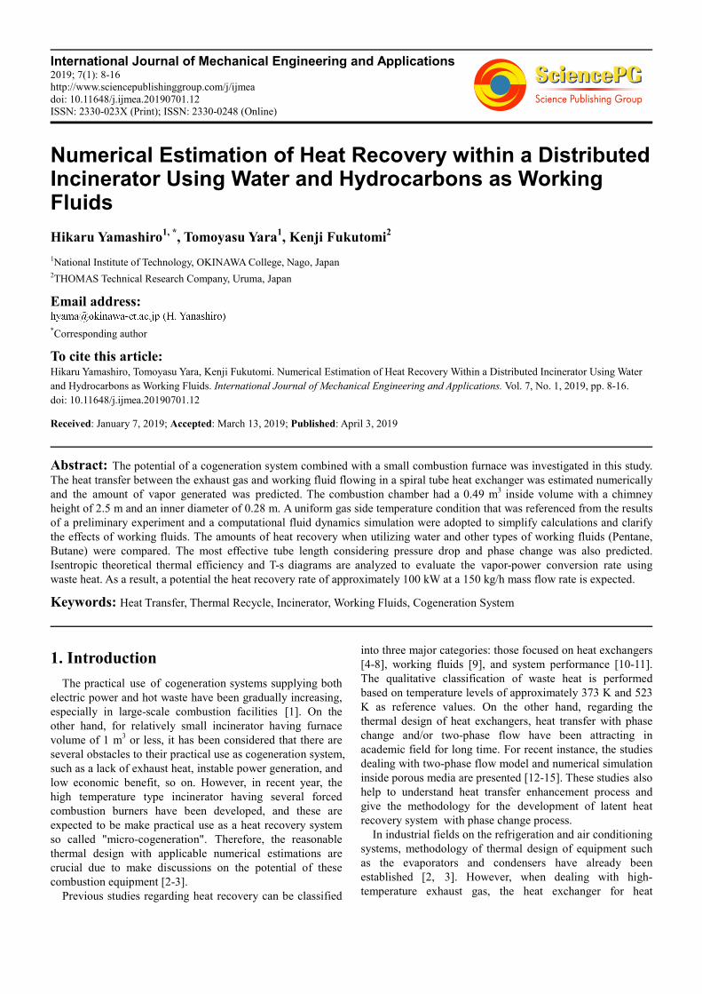
Figure 3 presents the schematics of a combustion furnace
with a heat exchanger. On the right side, enlarged view of
heat and mass transfer model for an element of a spiral tube
represented. A single stain-less steel pipe (SUS430) forms a
spiral along the inner wall of the chimney of the combustion
chamber. The working fluid supplied through the tube inlet
flows at a constant mass flow rate Mf according the equation
of continuity. The inside di and outside do tube diameters are
10 mm and 12 mm, respectively.
Figure 3. Combustion furnace with spiral tube, and heat transfer model and coordinates.
The heat and mass balance for the element of the spiral
tube is expressed as
1 0( )= −j fQ M h h (1)
where h is the specific enthalpy of the working fluid and Qj is
the heat transfer rate from the exhaust gas to the working
fluid across the tube wall element with the number “j”. The
subscripts 0 and 1 represent inlet and outlet of the tube
element, respectively. The Qj for the steady state is expressed
as
( )= −j f wf f i jQ T T d zα π (2)
2 ( ) ln( / )= −j j wg wf o iQ z T T d dπ λ (3)
{ }4 4( ) ( )j c r g g wg g f o jQ Q Q T T a T T d zα ε σ π= + = − + − (4)
where α is the heat transfer coefficient, and λ is the thermal
conductivity. The subscripts “w”, “f“, “g“ and “i” refer to the
wall, fluid, gas, and inside respectively. And subscripts “wf”
and “wg” refer to the wall at gas side and the wall at working
fluid side respectively. The values of αf and αg obtained from
the correlation equations proposed by Dittus-Boelter and
Chen referred in [2]. The Qj is represented by the sum of the
convection and radiation terms Qc and Qr respectively in the
gas side, as shown Eq. (4). The ε and a are the emissivity and
absorptivity values for the radiation heat transfer on the gas
side, respectively, and σ is the Boltzmann constant.
Temperature of working fluid Tf represents the arithmetic
average value evaluated by Eq. (5).
(5)
where the subscripts f, 0 and 1 refer to the fluid, inlet and
outlet for the tube element, respectively.
The exhaust gas temperature of Tg is given by an
approximate equation that is evaluated based on the results of
computational fluid dynamics simulations (see Figure 2).
This equation is defined as
Tg (y) = cn yn (6)
where the coefficients cn (n =0,1,2,3) take on different values
depending on the combustion state in the chamber. The
vertical coordinate y can be transformed into the spiral
coordinate z along a tube length with the spiral angle γ, as the
equation y = yj = zj sinγ. In this study, to clarify the effects of
a several kinds of working fluids on heat transfer
characteristics, the temperature distributions on the gas side
fffff TTTTT ∆+=+=2
1)(
2
1010
800℃ 1100℃ Main burner

International Journal of Mechanical Engineering and Applications 2019; 7(1): 8-16 11
were simplified as eq. (6). The emissivity ε and absorptivity
a of the gas side were set to the maximum values of ε = a = 1.
Table 1 present the temperature coefficients cn which
obtained in the preliminary experiment when the incinerator
keeped at the steady state without gas cooling by the air
nozzles. In this study, the gas side’s temperature was used
these values of cn for the assumption of gas side’s
temperature as boundary condition.
Table 2. Values of cn at the steady state in combustion.
n c0 c1 c2 c3
3 498.5 52.72 13.03 0.086
3.2. Pressure Drop
The pressure drop of the working fluid along the tube
element’s inside wall can be expressed as
2
200 1 0 0 1
1
1 ( )2
∆ = − = − + − + ∆
fj f lp p p u g y y p
ρ ρ ρρ
(7)
where ∆pj is the element’s total pipe loss sum of friction loss
and curved pipe loss. And where ρ, u and g represent density,
velocity and gravitational acceleration. And subscript “0” and
“1”, respectively. This value therefore can be expressed as
20( )
2
∆ = ∆ + ∆ = +
f jl f b f j j
i
zp g z z f u
d
ρρ ζ (8)
where fj is the pipe friction coefficient and ζ j is the curved
pipe loss coefficient for the tube element. These values are
given by the correlation equations proposed by Ito et al. [1].
3.3. Calculation Procedure
Calculation is performed in series of tube element based
on the boundary conditions of B. C. r = ro: T = Tg, z = z0, z1:
Mf0 = Mf1 (constant mass flowrate).
The values (p0, Tf0, Mf) of working fluid at the entrance to
the tube where corresponds to the top of chimney and the
temperature difference ∆Tf (=0.1K) are given as the initial
conditions. The obtained values of Tf1 and/or Tf (by eq.5) and
p1 are utilized for the calculation of the thermal properties.
The thermal properties are obtained from the subroutine
program in the NIST Ref-Prop Ver. 9 [12].
The enthalpy at the inlet h0 (p0, Tf0) and outlet h1 (p1, Tf1)
are also utilized in these calculations. Qj can be estimated
from Eqs. (1) and (5), where the unknown values Twg, Twf,
and zj (j = 1) are given by Eqs. (2) through (6). Based on the
calculated values, the thermal properties of working fluid are
then the recalculated and all unknown values are calculated
to derive a final solution. These calculation procedures
perform sequentially from j = 1 until n, where the desired
superheated vapor can be obtained. Regarding the transition
of the phase change, the temperature difference between the
calculated value of Tf1 and the saturation temperature of Ts1
was less than 0.001 (i.e. Ts1 - Tf < ±0.001). These values
represent the boiling incipience point and dry out point,
respectively. Therefore, the three heat transfer regions can be
specified by Tf1 < Ts1 for the compressed liquid, Ts1 = Tf1 for
two-phase transfer, and Ts1 < Tf1 for the superheated vapor.
The calculation in the two-phase region (Tf0 = Tf1), the
quality at the inlet x0, and ∆x are given as initial conditions.
The outlet x1 and Qj are calculated sequentially, similar to the
above calculations. The enthalpy h1 was defined as
, where h' and h" refer to
the saturation liquid and saturation vapor, respectively. Next,
the unknown values were calculated utilizing the procedure
described above. The calculations proceed from the
saturation liquid (x0 = 0) to the saturation vapor (x1 = 1),
which represents the end of the two-phase region. The values
of h' and h'' are based on the saturation temperature Ts1 for
the calculated outlet pressure p1.
3.4. Overall Heat Recovery Rate and Tube Length
The overall tube length of the heat exchange Zex is defined
by Eq. 9. The overall heat recovery rate Qh, and the pressure
drop ∆pex along Zex are also defined by Eq. (9).
1=
=∑n
ex j
j
Z z ,
1=
=∑n
h j
j
Q Q ,
1=
∆ = ∆∑n
ex j
j
p p (9)
n corresponds to the end of tube, where the working fluid
has reached the desired temperature or super heat ∆Tsup. The
pressure drop per unit length is defined by
∆�̅�� = ∆��� ���⁄ (10)
The vertical coordinate yn of the nth tube element of the
spiral-wound single tube is expressed in terms of the length zj
and spiral angle γ as
0
1
sin
=
= +∑n
n j
j
y y z γ (11)
where y0 is the vertical distance of the tube’s entrance from
the top of the chimney as shown Figure 3. Therefor the
overall tube length of heat exchanger is expressed as yex,
1
sin ( ) tan
=
= = −∑n
ex j i o
j
y z N D dγ π γ (12)
where Di is the inner diameter of the chimney, do is the outer
diameter of the tube, and the N is the number of turns along
the total tube length. The spiral tube angle is defined by the
following equations.
0 /21tan
2
− =
d
cRγ or (13)
0 /21tan
− =
d
iDγ , (14)
sinexZ h γ= (15)
rxhhxhxh 111 )1( +′=′′+′−=
sinexZ H γ=

12 Hikaru Yamashiro et al.: Numerical Estimation of Heat Recovery Within a Distributed Incinerator Using
Water and Hydrocarbons as Working Fluids
As shown Figure 3, based on the assumption that the spiral
tube for the heat exchanger runs from the near top of the
chimney to the bottom of the combustion chamber, Zex is
geometrically defined as the maximum tube length Zex,max of
a perfect circular coil without gaps.
The dimensions of the spiral tube and the initial conditions are
summarized in Table 3 and 4.
Table 3. Dimensions of spiral tube.
Material do [mm] di [mm] γγγγ [deg.]
Sus430 12.0 10.0 1.0
Table 4. Initial conditions of working fluid.
Kinds Tf0 [K] Mf [kg/h] p0 [MPa]
Water Butane Pentane 300 10-150 2.0
4. Numerical Results
4.1. Tube Length and Amount of Heat Recovery
Figure 4. Changes in temperature of working fluid: (a) Water, (b) Pentane.
The estimation of the transition points in the phase change
process is crucial on the thermal design of the heat exchanger.
Figure 4 present the temperature changes in the working fluid
in a single spiral tube with a constant mass flow rate Mf
ranging from 60 - 120 kg/h. The effects of working fluid can
understand by comparisons between Figure 4(a) and (b) for
water and pentane, respectively. The dotted lines in the figures
represent the variation in the gas side temperature by
assumption utilized the temperature distributions in Figure 2.
Initially, Tf increases gradually, then remains nearly constant in
the two-phase region, and finally increases gradually again in
the gas phase region. This tendency of the temperature profile
is similar for both water and pentane. This calculation is useful
for estimating the transition of the phase change in spiral tube.
The distance to the transition of the phase change moves
toward the down-flow side with an increasing Mf. This means
that a longer heat transfer distance is required to obtain the
larger amount of desired superheated vapor. In the case of
water, the tube outlet reaches a distance of more than 150 m
and is located inside the combustion chamber through chimney.
In case of pentane, the outlet reaches a relatively short distance
compared to water and is located inside the chimney.
Figure 5(a) and (b) present comparisons of the overall heat
recovery Qh for water and pentane flowing with the same Mf.
The notation Qh in the bar graph refers to the integrated
values in the liquid phase region, two-phase region, and gas
phase region, respectively. Qh increases nearly linearly with
an increasing Mf for both water and pentane.
The Qh ranges from 45 - 95 kW for water and 10 - 20 kW for
pentane, which indicates that the heat recovery rate of water is
approximately 4.5 times that of pentane in the Mf range of 45 -
95 kg/h. The ratios of heat recovery in the two-phase region for
water and pentane are approximately 72% and 39%, respectively.
This means a relatively larger heat recovery rate is obtained in
the two-phase region for water with large latent heat.
Figure 6 presents comparisons of the overall tube lengths Zex
for three types of working fluids: water, pentane, and butane.
The vertical axis in the graph represents both the Zex and yex
axis for the spiral tube heat exchanger. Zex corresponds to the
estimated distance to the outlet to obtain the desired
superheated vapor of 50 K. Zex increases nearly linearly with
increasing Mf. For an example at Mf = 120 kg/h, Zex represents
220 m for water, 102 m for pentane, and 88 m for butane. Zex
shows significant differences between working fluids.
Figure 5. Amount of recovered heat with changing mass flow rate: (a) Water,
(b) Pentane.
0
10
20
30
40
50
60
70
80
90
100
60 80 100 120
Rec
over
ed h
eat,
Qh
[kW
]
Mass flow rate, Mf [kg/h]
Vaper phase
Liquid-Vaper phase
Liquid phase
Vapor
Two-phase
Liquid
(a) Water
0
5
10
15
20
25
60 80 100 120
Rec
ov
ered
hea
t, Q
h[k
W]
Mass flow rate, Mf [kg/h]
過熱蒸気相
二相
液相
(b) PentaneVapor
Two-phaseLiquid

International Journal of Mechanical Engineering and Applications 2019; 7(1): 8-16 13
Figure 6. Comparisons of overall tube length.
4.2. Pressure Drop in Tube
Figure 7 presents comparisons of pressure drops per unit
length in the helical tube for three types of working fluids.
∆pex increases nearly linearly with Mf with same tendency for
water, pentane and butane, respectively. The ∆pex values for
pentane and butane are 27-30% lower than that for water. The
difference of the working fluid increases at high flow rate.
Figure 7. Pressure drop per unit tube length.
4.3. T-s Diagram and Theoretical Thermal Efficiency
In order to make a discussion on the potential of the heat
recovery-power conversion system, here virtually considers a
Rankine cycle combined with this incinerator. Figure 8(a)
and (b) present comparisons of the Rankine cycles on the T-s
diagrams for two kinds of working fluids of water and
pentane, respectively. The superheated vapor obtained by the
heat recovery (point h4) expands adiabatically to the
condensation temperature of Tc = 310 K, and the maximum
theoretical work Lth = Mf (h4 – h5) value can be obtained
during this process. In the case of water, the superheated
vapor at the state h4 is considered to enter into the two-phase
flow during this process, and it reaches the state of point h5
where the water vapor corresponds to the saturation pressure
pc for Tc. In the case of pentane, the superheated vapor at h4
reaches h5 as the superheated vapor corresponding to the pc
for Tc and then decreases in temperature until it reaches the
point h”5 of saturated vapor on the isobaric line (p = pc).
From these comparisons of T-s diagrams, it’s obvious that the
adiabatic heat drop ∆had of water vapor is significantly larger
than that of the pentane vapor.
Figure 8. Comparison of Rankine cycles on T-s diagram: (a) Water, (b)
Pentane.
The theoretical thermal efficiency ηth is defined by ηth = (h4
- h5) / (h4 - h1) and utilizes the specific enthalpy values h1-5 of
each state. Figure 9 presents the effects of condensation
temperature on theoretical efficiency. The ηth for water
ranges from 35 to 30 % in a Tc range of 280-320 K, decreases
gradually as Tc increases. The difference in thermal
efficiency between different working fluids is clearly visible.
Figure 9. Variation of theoretical thermal efficiency with condensate
temperature.
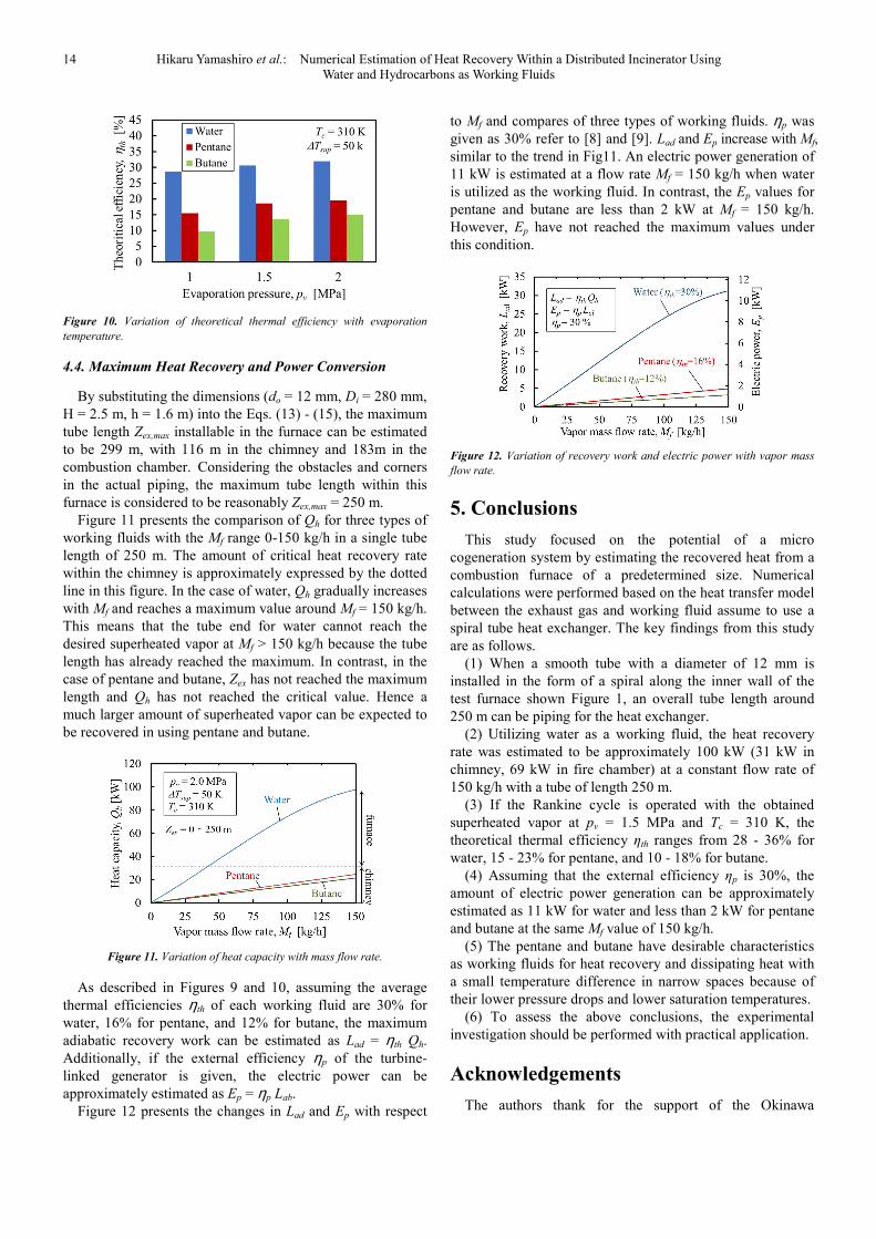
Figure 10 presents the effects of evaporation pressure pe on
ηth and compares three types of working fluids. ηth shows a
tendency to slightly increase as pv increases. To summarize
the information in Fig.9 and 10, the ηth is higher in the order
of water, pentane, and butane. These ranges are 28 - 36% for
water, 15 - 23% for pentane, and 10 - 18% for butane in the
pv ranges 1-2 MPa.
14 Hikaru Yamashiro et al.: Numerical Estimation of Heat Recovery Within a Distributed Incinerator Using
Water and Hydrocarbons as Working Fluids
Figure 10. Variation of theoretical thermal efficiency with evaporation
temperature.
4.4. Maximum Heat Recovery and Power Conversion
By substituting the dimensions (do = 12 mm, Di = 280 mm,
H = 2.5 m, h = 1.6 m) into the Eqs. (13) - (15), the maximum
tube length Zex,max installable in the furnace can be estimated
to be 299 m, with 116 m in the chimney and 183m in the
combustion chamber. Considering the obstacles and corners
in the actual piping, the maximum tube length within this
furnace is considered to be reasonably Zex,max = 250 m.
Figure 11 presents the comparison of Qh for three types of
working fluids with the Mf range 0-150 kg/h in a single tube
length of 250 m. The amount of critical heat recovery rate
within the chimney is approximately expressed by the dotted
line in this figure. In the case of water, Qh gradually increases
with Mf and reaches a maximum value around Mf = 150 kg/h.
This means that the tube end for water cannot reach the
desired superheated vapor at Mf > 150 kg/h because the tube
length has already reached the maximum. In contrast, in the
case of pentane and butane, Zex has not reached the maximum
length and Qh has not reached the critical value. Hence a
much larger amount of superheated vapor can be expected to
be recovered in using pentane and butane.
Figure 11. Variation of heat capacity with mass flow rate.
As described in Figures 9 and 10, assuming the average
thermal efficiencies ηth of each working fluid are 30% for
water, 16% for pentane, and 12% for butane, the maximum
adiabatic recovery work can be estimated as Lad = ηth Qh.
Additionally, if the external efficiency ηp of the turbine-
linked generator is given, the electric power can be
approximately estimated as Ep = ηp Lab.
Figure 12 presents the changes in Lad and Ep with respect
to Mf and compares of three types of working fluids. ηp was
given as 30% refer to [8] and [9]. Lad and Ep increase with Mf,
similar to the trend in Fig11. An electric power generation of
11 kW is estimated at a flow rate Mf = 150 kg/h when water
is utilized as the working fluid. In contrast, the Ep values for
pentane and butane are less than 2 kW at Mf = 150 kg/h.
However, Ep have not reached the maximum values under
this condition.
Figure 12. Variation of recovery work and electric power with vapor mass
flow rate.
5. Conclusions
This study focused on the potential of a micro
cogeneration system by estimating the recovered heat from a
combustion furnace of a predetermined size. Numerical
calculations were performed based on the heat transfer model
between the exhaust gas and working fluid assume to use a
spiral tube heat exchanger. The key findings from this study
are as follows.
(1) When a smooth tube with a diameter of 12 mm is
installed in the form of a spiral along the inner wall of the
test furnace shown Figure 1, an overall tube length around
250 m can be piping for the heat exchanger.
(2) Utilizing water as a working fluid, the heat recovery
rate was estimated to be approximately 100 kW (31 kW in
chimney, 69 kW in fire chamber) at a constant flow rate of
150 kg/h with a tube of length 250 m.
(3) If the Rankine cycle is operated with the obtained
superheated vapor at pv = 1.5 MPa and Tc = 310 K, the
theoretical thermal efficiency ηth ranges from 28 - 36% for
water, 15 - 23% for pentane, and 10 - 18% for butane.
(4) Assuming that the external efficiency ηp is 30%, the
amount of electric power generation can be approximately
estimated as 11 kW for water and less than 2 kW for pentane
and butane at the same Mf value of 150 kg/h.
(5) The pentane and butane have desirable characteristics
as working fluids for heat recovery and dissipating heat with
a small temperature difference in narrow spaces because of
their lower pressure drops and lower saturation temperatures.
(6) To assess the above conclusions, the experimental
investigation should be performed with practical application.
Acknowledgements
The authors thank for the support of the Okinawa

International Journal of Mechanical Engineering and Applications 2019; 7(1): 8-16 15
Prefecture Science and Technology Innovation Project in
2017-2018. We also appreciate the coordinating of Dr. Y.
Nagawa and Dr. I. Matsui of the Okinawa Science and
Technology Promotion Center.
Nomenclature
a, b, c, h, H dimensions of combustion furnace [m]
cn gas temperature coefficient [-]
d tube diameter [m]
D diameter of chimney [m]
g gravitational acceleration [m/s2]
h specific enthalpy [J/kg]
M mass flow rate [kg/s] or [kg/h]
N number of turn [time]
p pressure [Pa]
∆p pressure drop [Pa]
Q heat transfer rate [W]
q heat flux [W/m2]
Rc coil radius of spirally wound tube [m]
s specific entropy [J/(kg.K)]
T temperature [K]or[°C]
u velocity [m/s]
x quality of working fluids [—]
y vertical coordinate or vertical head [m]
distance or length [m]
Z overall tube length [m]
z spiral coordinate or length of element [m]
∆zb bending loss head of tube element [m]
∆zf friction loss head of tube element [m]
α heat transfer coefficient [W/(m2.K)]
ε emissivity [—]
a absorptivity [—]
λ thermal conductivity [W/(m.K)]
σ Stefan-Boltzmann constant [W/(m2.K
4)]
γ spiral angle [rad.]
ρ density [kg/m3]
Subscript
ad adiabatic
b boiling
c convection
ex heat exchanger
f working fluid
g gas or gas side
i inside or inner
j element’s number
l loss
o outside
p power
r radiation
w wall
wg gas side’s wall
fg fluid side’s wall
0 inlet
1 outlet
References
[1] Takuma Co., Ltd., Environmental Technology Research Association, “Waste Incineration Technology”, Ohm-Sha, 2010, pp. 1-200.
[2] The Japan Society of Mechanical Engineers, Heat Transfer Data Book 5 th ed., 2009, pp. 105-204.
[3] The Japan Society of Refrigerating and Air Conditioning Engineers, Refrigeration, Special ed., Vol. 090, No. 1047, 2015, pp. 3-22.
[4] R. Echigo, K. Hanamura, Y. Takahashi, M. Okuyama, S. Jugjai, A. Hagiwara, Y. Usami and N. Funahashi, “Heat transfer analysis for a tubular methane-steam reformer with a porous radiative converter”, Transactions of the Japan Society of Mechanical Engineers, Series B, Vol. 57, No. 539, 1991, pp. 163-169.
[5] J. Yamashita and Y. Utaka, “On prediction of heat exchanger performance for latent heat recovery using flue gas”, Transactions of the Japan Society of Mechanical Engineers, Series B, Vol. 80, No. 818, 2014, pp. 1-14.
[6] A. S. Hegazy, “Possible waste heat recovery in the condenser of a regenerative steam cycle”, Journal of Thermal Science and Technology, Vol. 2, No. 1, 2007, pp. 1-12.
[7] H. Takamatsu, H. Yamashiro, N. Takata, H. Honda, “Vapor absorption by LiBr aqueous solution in vertical smooth tubes”, International Journal of Refrigeration, Vol. 26, 2003, pp. 659-666.
[8] Le Minh Nhut, Young-Sub Moon, Youn Cheol Park, “A study on energy optimization of heat exchanger in a gasification system”, International Journal of Mechanical Engineering and Applications, Vol. 4, No. 3, 2016, pp. 123-129.
[9] H. Hasegawa and S. Kimishima, “An investigation on working fluid selection of Rankine-Cycle driven by low grade heat with small temperature difference to environment”, Transactions of the Japan Society of Refrigerating and Air Conditioning Engineers, Vol. 30, No. 1, 2013, pp. 1-12.
[10] P. A. Kew and K. Cornwell, “Development of a highly compact steam generator”, Applied Thermal Engineering, Vol. 25, 2005, pp. 2604-2614.
[11] S. Tokuda and T. Osanai, “Exergie-Heat recovery analysis for exhaust gas in the boiler system”, Transactions of the Japan Society of Mechanical Engineers, Series B, Vol. 50, No. 449, 1984, pp. 91-97.
[12] Xin, Z. Rao, X. You, Z. Song, D. Han, “Numerical investigation of vapor–liquid heat and mass transfer in porous media”, Energy Conversion and Management, Vol. 78, 2014, pp. 1-7.
[13] Fei He, J. Wang, “Numerical investigation on critical heat flux and coolant”, Energy Conversion and Management, Vol. 80, 2014, pp. 591-597.
[14] O. R. Alomar, M. A. A. Mendes, D. Trimis, S. Ray, “Numerical simulation of complete liquid-vapour phase change process inside porous media using smoothing of diffusion coefficient”, International Journal of Thermal Sciences, Vol. 86, 2014, pp. 408-420.

16 Hikaru Yamashiro et al.: Numerical Estimation of Heat Recovery Within a Distributed Incinerator Using
Water and Hydrocarbons as Working Fluids
[15] O. R. Alomar, M. A. A. Mendes, S. Ray, D. Trimis, “Numerical investigation of complete evaporation process inside porous media using staggered and non-staggered grid arrangements”, International Journal of Thermal Sciences, Vol. 129, 2018, pp.56-72.
[16] O. R. Alomar, R. R. Mohammed, M. A. A. Mendes, S. Ray, D. Trimis, “Numerical investigation of two-phase flow in
anisotropic porous evaporator”, International Journal of Thermal Sciences, Vol. 135, 2019, pp. 1-16.
[17] Lemmon, E. W., Huber, M. L. and Mc Linden, M. O., NIST REFPROP Ver.9 (2010).