Embed Size (px)
Citation preview

A R C H I V E S O F M E T A L L U R G Y A N D M A T E R I A L S
Volume 56 2011 Issue 2
DOI: 10.2478/v10172-011-0046-4
J. ADAMUS∗, P. LACKI∗, W. WIĘCKOWSKI∗∗
NUMERICAL SIMULATION OF THE FINE BLANKING PROCESS OF SHEET TITANIUM
SYMULACJA NUMERYCZNA PROCESU WYKRAWANIA DOKŁADNEGO BLACH TYTANOWYCH
The present study has been undertaken in order to investigate the new possibilities of improvement in quality of thecut-surface of titanium blanks. For the intended purpose, a number of numerical simulations of the blanking process werecarried out.
Fine blanking is one of the most often used methods of finished product manufacturing. Application of blanking withreduced clearance or blanking with material upsetting by V-ring indenter allows for obtaining the high quality cut-surfacewhich does not need further machining. Application of the finite element method (FEM) for numerical simulations allows foreffective analysis of the fine blanking processes.
In the paper the results of numerical simulation of fine blanking for a disk made of Grade 2 sheet titanium have beenpresented. The calculations were carried out using ADINA System v. 8.6 based on FEM. Determination of the effect ofclearance between cutting edges, and presence and location of V-ring indenter on the stress and strain distribution in shearingzone was the main goal of the work. The numerical simulations showed the effect of tool geometry on a course of blankingprocess and consequently on the quality and shape of the cut-surface. Based on the numerical simulation it is only possible todeduce the cut-surface appearance, thus the numerical simulations should be completed with experimental tests.
Keywords: fine blanking, sheet titanium, numerical modelling
Niniejsza praca została wykonana w celu zbadania nowych możliwości poprawy jakości powierzchni przecięcia wykrojektytanowych. W tym celu wykonano szereg symulacji numerycznych procesu wykrawania.
Wykrawanie dokładne jest najczęściej stosowaną metodą otrzymywania wyrobów gotowych. Zastosowanie wykrawaniaze zmniejszonym luzem lub wykrawania ze spęczaniem za pomocą klinowej grani pozwala na otrzymanie wysokiej jakościpowierzchni przecięcia, która nie wymaga dalszej obróbki mechanicznej. Wykorzystanie w symulacjach numerycznych metodyelementów skończonych (MES) pozwala na efektywną analizę procesów wykrawania dokładnego.
W artykule zaprezentowano wyniki symulacji numerycznej wykrawania dokładnego krążka z blachy tytanowej Grade 2.Obliczenia wykonano przy użyciu programu ADINA System v. 8.6 opartego na MES. Głównym celem pracy było określeniewpływu luzu pomiędzy krawędziami tnącymi oraz obecności klinowej grani na dociskaczu na rozkład naprężeń i odkształceńw obszarze cięcia. Obliczenia numeryczne wykazały wpływ geometrii narzędzi na przebieg procesu wykrawania, a tym samymna jakość i kształt powierzchni przecięcia. Opierając się na symulacjach numerycznych można jedynie wnioskować o wyglądziepowierzchni przecięcia, dlatego symulacje numeryczne powinny być uzupełnione badaniami doświadczalnymi.
1. Introduction
The paper results from explore the new possibilitiesof increase in quality of the cut-surface of titanium ele-ments, which are generally cut by conventional methodsi.e. by two rigid cutting edges (a guillotine or a blankingdie). Blanking is not only used as a first step in prepar-ing blanks for further forming but also in manufacturingfinished products, which are then ready for assemblywithout the need for additional machining. Fast produc-tion development has lead to an increase in demand for
high-quality products. This also concerns shared blanksfor which cleanly cut-surface, precise geometry and highdimensional accuracy are very essential. In the case ofsome elements it is important to keep: surface flatness,identical dimensions through the full thickness of thepart and the perpendicularity of the sidewall. In thesecases fine blanking can be applied [1-3]. Burrs arisingin conventional blanking can cause some surface defectssuch as scratches and dents on the drawn-parts, whichare difficult to eliminate. Moreover, burrs initiate cracks
∗ CZĘSTOCHOWA UNIVERSITY OF TECHNOLOGY FACULTY OF CIVIL ENGINEERING, 42-218 CZĘSTOCHOWA, 3 AKADEMICKA STR., POLAND∗∗ CZĘSTOCHOWA UNIVERSITY OF TECHNOLOGY INSTITUTE OF METAL FORMING, QUALITY ENGINEERING AND BIOENGINEERING, 42-200 CZĘSTOCHOWA, 21 ARMII KRAJOWEJAV., POLAND
432
Fig. 1. Conventional (a) and fine blanking with material upsetting (b)
during some stamping operation like flanging. So as toimprove the cut-surface quality much experimental re-search and many numerical simulations have been car-ried out [4-14]. They have been aimed at determin-ing such parameters as: cutting speed, clearance, toolgeometry etc. Unfortunately, the current knowledge ofsheet-titanium forming and also shearing of titaniumsheets is rather poor. It results from the fact that titaniumand its alloys are used in commercial scale of productionfor a short time. In literature, there are very few worksin the range of subject matter [15,16] so the authors de-cided to carry out numerical simulation of fine blankingprocess of sheet titanium.
Fine blanking is an industrial manufacturing tech-nique used for achieving near net shape elements.The main characteristic of the process is high quali-ty cut-surface, which does not need further machining.Blanking with reduced clearance or blanking with ma-terial upsetting by V-ring indenter (Fig. 1) are the mostfrequent methods applied for blanking non-ferrous ma-terials. The fundamental nature of these methods is anassurance of a favourable stress and strain state beforeand during the shearing process, what guarantees therequired quality of cut-surface. Tool geometry, whichstrongly depends on the blanking die construction, andproperties of the blanked material are the main factorsaffecting stress state in shearing zone and consequentlythe course of fine blanking [1,3,16-20].
Proper choice of the blanking parameters al-lowing for obtaining high quality elements requireslabour-consuming experiments or they can be specifiedbasing on the numerical analysis of blanking process.Application of FEM in simulation of metal formingprocesses, also blanking, enables analysis of subsequentstages of the process and prediction of the results ofthe assumed process parameters, and limitation of costlyexperiments [10,16,20,21].
2. Goal and scope of the numerical analyses
Determination of the influence of:– clearance between cutting edges of the die and
punch,– application of flat blank-holder or blank-holder with
V-ring indenteron the stress and strain state in cutting zone was themain goal of the numerical simulations of blanking.
In the paper some numerical calculation results offine blanking for a disk made of 1-milimetre sheet ti-tanium Grade 2 are presented. Fracture initiation andits propagation have been determined. The selection ofoptimal parameters affecting stress state assures the re-quired cut-surface quality. On the basis of cutting zoneshape and material fracture it is possible to deduce theprobable appearance of the cut-surface. However, the nu-merical simulations of fine blanking, which are contin-uation of research on blanking [15,16] do not allow forfull description of cut-surface. Therefore, the experimen-tal investigations should be a complement to numericalmodelling [1,6,13,15].
3. Numerical simulation of fine blanking
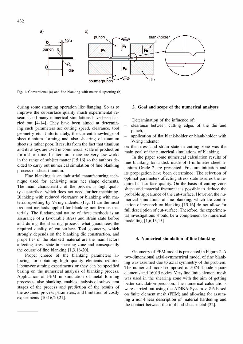
Geometry of FEM model is presented in Figure 2. Atwo-dimensional axial-symmetrical model of fine blank-ing was assumed due to axial symmetry of the problem.The numerical model composed of 5074 4-node squareelements and 16015 nodes. Very fine finite element meshwas used in the shearing zone with the aim of gettingbetter calculation precision. The numerical calculationswere carried out using the ADINA System v. 8.6 basedon finite element mesh (FEM) and allowing for assum-ing a non-linear description of material hardening andthe contact between the tool and sheet metal [22].
433
Fig. 2. Discrete model of the fine blanking process
Perfectly rigid material model for blanking tools andisotropic, elastoplastic material model for the blankedsheet-metal (model based on the von Mises criterion as-sociated with the law of plastic flow, using von Misesplasticity function and a principle of isotropic hardening)were assumed in the calculations. Experimentally deter-mined material parameters adopted for the calculationsare presented in Table 1.
TABLE 1Material properties of the sheet EN AW-1070A
Tensilestrength
Rm [MPa]
Yieldstrength
R0.2 [MPa]
Young’smodulusE [GPa]
Poisson’sratioν
σp=Kϕn
K[MPa] n
522 368 110 0.37 822 0.18
A constant die diameter Dd was assumed for thecalculation, whereas clearance value c was determinedthrough changing the punch diameter DP. Simulation offine blanking with material upsetting was carried out fordifferent locations of V-ring indenter dV with the sameclearance of 1% of the sheet metal thickness. Addition-ally the simulation of fine blanking without indenter andcounter-punch was carried out for variable clearance val-ues. The parameters, which were assumed in the calcu-lations, were presented in Table 2.
Contact phenomenon between mating surfaces ofthe tool and sheet metal was described using a modelof Coulomb friction:
τ f = µσn(1)where: τ f and σn−shear and normal stress in rela-
tion to friction surface, respectivelyand µg friction coefficient.
Modelling of blanking process requires employinga fracture criterion for numerical model which allowsfor analysis of the process due to the course of mate-rial separation [1,7,23]. In the numerical simulation of
fine blanking process material separation was modelledbased on the criterion proposed in [5,18]. It considersappearance of initial cracking at the location where thefollowing formula holds true:
∫ ε f
0
(σ∗
σ
)dε = C (1)
where: σ* – maximum tensile stress, ε f –ductile-fracture strain, ε – effective strain, σ – effectivestress, C – constant, depending on the material kind.
TABLE 2Parameters assumed in FEM model for the fine blanking process
Parametr valueDd[mm]
Dp[mm]
c = Dd − Dp[mm]
Rp[mm]
Rd [mm]
Rv1[mm]
Rv2[mm]
θg◦]
V-ring indenter position dv[mm]
holding down force Fb[N]
counter-punch force Fc[N]
V-ring indenter height hv[mm]
friction coefficient µ
31.7
31.69; 31.60
0.01; 0.1
0.025
0.025
0.3
0.1
90
0.4; 0.7; 1.0
64 000
16 000
0.3
0.15
Assuming that the highest strains occur along thecutting line and the value of stress is constant in blankingoperations, the above mentioned criterion can be reducedto the following formula:
∫ ε f
0dε ≈ C1 (2)
finally, it can be assumed that material separation occursin the location with the given value of the effective strainC′1 :
n∑
0
(∆εe) ≈ C ′1 (3)
where: n – calculation step number, ∆εe – increment ofstrain in the element.
According to the assumed simplification, a fracturecriterion was modelled by determination of a maximalpermissible effective plastic strain ε
pe = 0.82. Value of
the effective plastic strain was determined experimental-ly in tensile test according to the method described in[1]. At the moment when fracture criterion is satisfied atthe point of integration of the given element, the elementis removed from the numerical model.
434
4. Numerical simulation results
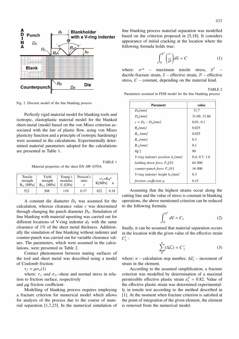
Blanking with the reduced clearance between cut-ting edges of the die and punch is the simplest fine blank-ing method. Calculation results showed the essential in-fluence of clearance on strain and stress values in theshearing zone and consequently on the blanking courseand cut-surface shape. The decrease in clearance limitsbending moment acting on the blank due to the lateraldisplacement between cutting edges. Bending moment isresponsible for the tensile stresses in shearing zone. Acomparison of plastic strain distribution between conven-tional blanking (c=0.10 mm) and blanking with reducedclearance of c=0.01 mm for the punch displacement of0.14 mm is shown in Figure 3. Plastic strains are less in-tensive for the conventional blanking (Fig.3a) in compar-ison to the fine blanking (Fig.3b). During fine blankingplasticised zones spreading from the cutting edges of thedie and punch, where the plastic deformations initiate,join earlier. Clearance reduction leads to the delay offracture initiation. All these give smoother cut-surface.
Blanking with reduced clearance and extra upset-ting of the blanked material is another very effectivefine blanking method. To that end a special constructionof the blanking dies, which assures reduction of tensilestresses in shearing zone, are used. Application of flatblank-holder and counter-punch is the simplest methodof fine blanking with material compression. In practiceneither properly selected clearance nor application of theflat blank-holder are enough effective in elimination oftensile stresses. As it turned out, an important technolog-ical breakthrough in the field of tooling for fine blankingwas the application of blank-holder with V-ring indenter,which generates favourable changes in strain and stressstate in shearing zone. As a consequence high qualitycut-surface is produced. The main disadvantage of thismethod is the necessity for application of the specialtools and presses, and therefore higher cost when com-pared to traditional blanking operations.
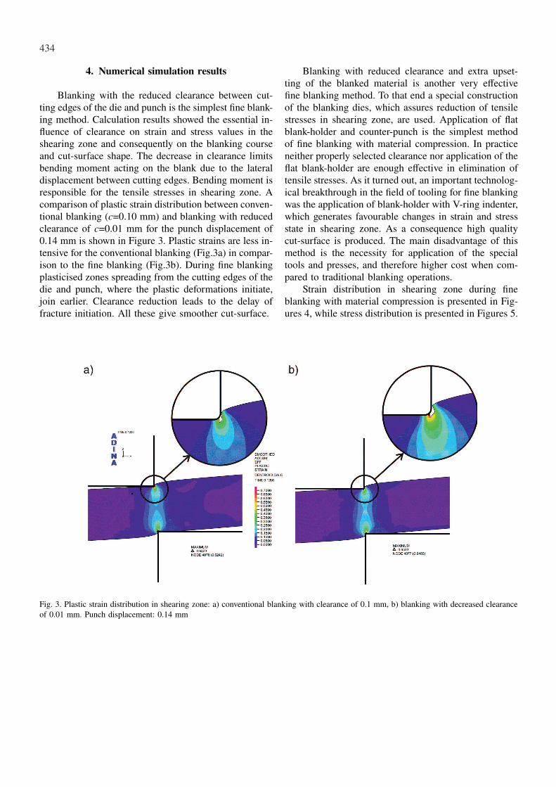
Strain distribution in shearing zone during fineblanking with material compression is presented in Fig-ures 4, while stress distribution is presented in Figures 5.
Fig. 3. Plastic strain distribution in shearing zone: a) conventional blanking with clearance of 0.1 mm, b) blanking with decreased clearanceof 0.01 mm. Punch displacement: 0.14 mm

435
Fig. 4. Distribution of plastic strains in cutting zone for punch displacement of 0.14 mm: a) without indenter, b) dv=0.4 mm, c) dv=0.7 mm,d) dv=1.0 mm
Fig. 5. Effective stress distribution in shearing zone at the moment of blank-holder squeezing into material for different position of V-ringindenter: a) without indenter, b) dv=0.4 mm, c) dv=0.7 mm, d) dv=1.0 mm
436
Presence of V-ring indenter affects strain state. Ad-ditional plastic strains occur in the vicinity of V-ring in-denter. As a result material undergoes hardening. Conse-quently, material being in the direct shearing zone flowsrather in cutting direction than away from the punch.The plasticised material affects the material being inthe direct zone of cutting line by producing compres-sive stresses, so the tensile stresses which are conduciveto fracture, are reduced. However excessive distance ofthe indenter limits the effect of material strengtheningon plastic strains in direct cutting zone, thereby limitsthe effect of compensation of tensile stresses, what pre-vents from achieving the expected effects of fine blank-ing with upsetting. Value and especially range of plasticstrains strongly depends on geometry and location ofV-ring indenter. Too low distance of V-ring from rimof blank-holder causes the stresses increase in materialalong the line between cutting edge of the punch and tipof the indenter, what may contributes to unforeseen lossin material cohesion.
5. Conclusions
The authors collaborate with the firm producing ti-tanium elements. Many of them are made by blanking.Insufficient quality of the cut-surface requires additionalmachining – grinding, which is very troublesome. There-fore the authors made an attempt at elimination of thisoperation by using the fine-blanking instead of the con-ventional one.
Application of FEM in numerical simulation enablesanalysis of different blanking methods using differentinitial process parameters (clearance, location of V-ringindenter etc.). Calculation results show the essential in-fluence of the considered geometrical parameters on theblanking course and in consequence on shape of thecut-surface:– V-ring indenter generates additional plastic strains
in its vicinity, which affects material hardening. Asa consequence, material being in the direct shear-ing zone flows rather in cutting direction than awayfrom the punch so a concentration of plastic strainsin direct shearing zone and therefore early materialseparation compared to the process of blanking withflat blank-holder. Value and especially range of plas-tic strains strongly depends on geometry and locationof V-ring indenter,
– excessive distance of the indenter limits the effect ofmaterial hardening and the effect of compensationof tensile stresses, what prevents from achieving theexpected effects of fine blanking with upsetting,
– too low distance of V-ring from rim of blank-holdercauses the stresses increase in material along the line
between cutting edge of the punch and tip of the in-denter, what may contributes to unforeseen loss inmaterial cohesion,
– the calculation results allow for prediction of mater-ial fracture and deduction about the probably shapeof blank cut-surface,
– the simulations of the fine blanking process requirefurther experimental verification in order to confirmthe legitimacy of the adopted assumptions for thedeveloped numerical model and usefulness of theemployed material cracking criterion.
– the carried out numerical simulations allowed the au-thors for selection the proper geometry of the blank-ing tools, especially geometry and position of V-ringindenter. The real blanking tool will be made in thenearest future, so the calculation results will be veri-fied experimentally and the results will be presentedin further publications.
Acknowledgements
Financial support of Structural Funds in the Operational Pro-gramme – Innovative Economy (IE OP) financed from the EuropeanRegional Development Fund – Project ”Modern material technologiesin aerospace industry”, Nr POIG.01.01.02-00-015/08-00 is gratefullyacknowledged.
REFERENCES
[1] S. K u t, An influence of some parameters on qualityof fine-blanked products, in Polish: Wpływ wybranychparametrów na jakość wyrobów w procesie wykrawa-nia dokładnego, Oficyna Wydawnicza Politechniki Rzes-zowskiej, Rzeszów (2006).
[2] T.C. L e e, L.C. C h a n, B.J. W u, Straining behav-iour in blanking process – fine blanking vs. conven-tional blanking, J. Mater. Process. Technol. 48, 105-111(1995).
[3] Z. P o l a ń s k i, Blanking, in Polish: Wykrawanie,WNT, Warszawa (1978).
[4] D. B r o k k e n, W.A.M. B r e k e l m a n s, F.P.T.B a a i j e n s, Predicting the shape of blanked products:a finite element approach, J. Mater. Process. Technol.103, 51-56 (2000).
[5] F. F a u r a, A. G r a c i a, M. E s t r e m, Finite elementanalysis of optimum clearance in the blanking process,J. Mater. Process. Technol. 80-81, 121-125 (1998).
[6] A.M. G o i j a e r t s, Y.W. S t e g e m a n, L.E. G o -v a e r t, D. B r o k k e n, W.A.M. B r e k e l m a n s,F.P.T. B a a i j e n s, Can a new experimental and numer-ical study improve metal blanking? J. Mater. Process.Technol. 103, 44-50 (2000).
[7] R. H a m b l i, M. R e s z k a, Fracture criteria identi-fication using an inverse technique method and blank-

437
ing experiment, Int. J. of Mechanical Sciences 44,1349-1361 (2002).
[8] N. H a t a n a k a, K. Ya m a g u c h i, N. T a k a k u r a,Finite element simulation of the shearing mechanism inthe blanking of sheet metal, J. Mater. Process. Technol.139, 64-70 (2003).
[9] N. H a t a n a k a, K. Ya m a g u c h i, N. T a k a k u -r a, T. I i z u k a, Simulation of sheared edge formationprocess in blanking of sheet metals, J. Mater. Process.Technol. 140, 628-634 (2003).
[10] S.K. M a i t i, A.A. A m b e k a r, U.P. S i n g h, P.P.D a t e, K. N a r a s i m h a n, Assessment of influenceof some process parameters on sheet metal blanking.J. Mater. Process. Technol. 102, 249-256 (2000).
[11] H. M a r o u a n i, A. B e n I s m a i l, E. H u g,M. R a c h i k, Numerical investigations on sheet metalblanking with high speed deformation, Materials andDesign 30, 3566-3571 (2009).
[12] H. M a r o u a n i, A. B e n I s m a i l, E. H u g, M.R a c h i k, Rate-dependent constitutive model for sheetmetal blanking investigation, Materials Science and En-gineering A 487, 162-170 (2008).
[13] Z. T e k i n e r, M. N a l b a n t, H. G u r u n, An ex-perimental study for the effect of different clearanceson burr, smooth-sheared and blanking force on alumini-um sheet metal. Materials and Design 27, 1134-1138(2006).
[14] M. Jr. V a z, J. D. B r e s s a n, A computational ap-proach to blanking processes, J. Mater. Process. Technol.125-126, 206-212 (2002).
[15] J. A d a m u s, The Influence of Cutting Methods on theCut-Surface Quality of Titanium Sheets, Key Engineer-ing Materials 344, 185-192 (2007).
[16] J. A d a m u s, P. L a c k i, Modelling of blankingprocess of sheet titanium, in Polish, Hutnik – Wiado-mości Hutnicze 76 (8), 552-554 (2009).
[17] T.S. K w a k, Y.J. K i m, W.E. B a e, Finite elementanalysis on the effect of die clearance on shear planesin fine blanking, J. Mater. Process. Technol. 130-131,462-468 (2002).
[18] T.S. K w a k, Y.J. K i m, M.K. S e o, W.B. B a e, Theeffect of V-ring indenter on the sheared surface in thefine-blanking process of pawl, J. Mater. Process. Tech-nol. 143-144, 656-661 (2003).
[19] H. S a m u e l, FEM simulation and experimental analy-sis of parameters of influence in blanking process, J.Mater. Process. Technol. 84, 97-106 (1998).
[20] T. S u t a s n, J. M a s a h i k o, Investigation mechanismof V-ring indenter geometry in fine-blanking process,Key Engineering Materials 410-411, 305-312 (2009).
[21] N. M o l e, B. S t o k, Finite element simulation of sheetfine blanking process, Int. J. Mater. Form., 2 Suppl 1,551-554 (2009).
[22] ADINA System v. 8.3. Theory and Modelling Guide,vol. I. ADINA R&D, Inc., (2005).
[23] M. F a r z i n, H.R. J a v a n i, M. M a s h a y e k h i,R. H a m b l i, Analysis of blanking process using var-ious damage criteria, J. Mater. Process. Technol. 177,287-290 (2006).
Received: 10 January 2005.