Embed Size (px)
Citation preview

Magna Carta—Tūtohinga Nui
We will sell to no man, we will not deny or defer to any man either justice or right.
Kore rawa e hoko ki te tangata, e kore e whakakāhoretia,
e tautuku rānei te tangata ki te ture, tika ranei.
NZS 1170-5 (S1) (2004) (English): Structural designactions - Part 5: Earthquake actions - New ZealandCommentary [By Authority of New Zealand StructureVerification Method B1/VM1]


OJ STANDARDS
NEW ZEALAND PAER E WA AOT E AROA
NZS 1170.5 Supp 1:2004
New Zealand Standard ™
Structural Design Actions
Part 5 : Earthquake actionsNew Zealand - Commentary

2
NZS 1170.5 Supp 1 :2004 This New Zealand Standard was prepared by Technical Committee BO-006-04-11, Earthquake Loadings in New Zealand under Joint Committee BO-006, General Design Requiremems and Loading on Structures. It was approved by the Council of Standards New Zealand on 2 I December 2004. It was published on 22 December 2004.
The following are the members of Technical Committee BO-006-04:
Mr Andrew King (Chair) Prof. Des Bull Mr Charles Clifton Dr David Dowrick Mr Rob Jury Dr Graeme McVerry Prof. Peter Moss Dr Arthur O'Leary
The following are represented on Committee BO-006:
Assoeiation of Consulting Engineers Australia Australian Building Codes Board Australian In~titute of Steel Construction Building Research Association of New Zealand Cement and Concrete Association of Australia CSIRO, Building, Construction and Engineering Cyclone Testing Station - James Cook University Electricity Supply Association or Australia Housing Industry Association Institution of Engineers Australia Institution of Professional Engineers New Zealand Master Builders Australia New Zealand Heavy Engineering Research Association Steel Reinforcement Institute of Australia University of Canterbury New Zealand University of Melbourne University of Newcastle
Keeping Standards up-to-date Standards are living documents which refleet progress in science, technology and systems. To maintain their currency, all Srandards are periodically reviewed. and new editions are published. Between editions, amendments may be issued. Standards may also be withdrawn. It is important that readers assure themselves they are using a current Standard. which should include any amendments which may have been published since the Standard was purchased.
Detailed information about New Zealand Standards can be found by visiting the Standards New Zealand web site at and looking up the relevant Standard in the on-line catalogue.
Alternatively, Standards New Zealand puhlish an annual primed Catalogue with full details of all current Standards. For more frequem listings or notification of revisions, amendments and withdrawals, Standards New Zealand offer a number of update options. For information ahout these services, please contact Standards New Zealand.
We also weleome suggestions for improvement in our Standards, and especially encourage readers to notify us immediately of any apparent inaccuracies or ambiguities. Please address your comments to the Chief Executive of Standards New Zealand at the address shown on the back eover.
This Standard was issued in comment as DR 00903.

NZS 1170.5 Supp 1 :2004
NZS 1170.5 Supplement 1 :2004
Structural design actions
Part 5: Earthquake actions -New Zealand - Commentary (Supplement to NZS 1170.5:2004)
Previous edition NZS 4203:1992 (Part)
COPYRIGHT
©Standards New Zealand
All rights are reserved. 1'10 part of this work may be reproduced or copied in any form or by any means, electronic or mechanical, including photocopying, without the written permission of the publisher.
Published by Standards New Zealand, Private Bag 2439, Wellington 6020.
ISBN 1-86975-019-5

NZS 1170.5 Supp ] :2004 2
PREFACE
This Commentary is intended to be read in conjunction with NZS 1170.5:2004 referred to here as the "Standard." It is intended to provide background to the various provisions in the Standard, to suggest approaches that may satisfy the intent of the Standard, and if appropriate, describe differences between this and previous editions of the Standard. References are provided for further reading and these are given at the end of each section of the Commentary.
Commentary Clauses are not mandatory.
Clause numbering of the Commentary is identical to that of the Standard except that Clauses are prefixed with the letter 'C'. A cross-reference such as 5.4.1.2 refers to that Clause in the Standard, while C5.4.1.2 refers to the corresponding commentary Clause. Commentary is not provided to all Clauses in the Standard. Some commentary Clauses do not have a corresponding Clause in the Standard.

NZS 1170.5 Supp 1:2004
CONTENTS
Page SECTION CI SCOPE AND GENERAL .................................................................................. 5
C1.1 S(~OPE ................................................................................................................... 5 Cl.2 DETERMINATION OF EARTHQUAKE ACTIONS ............................................ 5 C 1.3 LIMIT STATES ..................................................................................................... 5 C 1.4 SPECIAL STUDIES .............................................................................................. 6 Cl.5 REFERENCED DOCUMENTS ............................................................................. 6
SECTIC)N C2 VERIFICATION ............................................................................................... 7 C2.1 GENERAL REQ UIRENIENTS .............................................................................. 7 C2.2 STRUCTURAL TYPES ....................................................................................... 11 C2.3 ULTIMATE LIMIT STATE VERIFICATION .................................................... 12 C2.4 SERVICEABILITY LIMIT STATE VERIFICATION ........................................ 13 C2.5 DEFORMATION CONTROL .............................................................................. 15 C2.6 STRU(~TlJRE PARTS ......................................................................................... 15 C2.7 PRIMARY AND SECONDARY SEISMIC MEMBERS ..................................... 15
SECTION C3 SITE HAZARD SPECTRA ............................................................................. 17 C3.1 ELASTIC SITE SPECTRA FOR HORIZONTAL LOADING ............................. 17 C3.2 SITE HAZARD SPECTRA FOR VERTICAL LOADING ................................... 28
SECTION C4 STRUCTURAL CHARACTERISTICS ........................................................... 31 C4.1 PERIOD OF VIBRATION ................................................................................... 31 C4.2 SEISMIC WEIGHT AND SEISMIC MASS ........................................................ 32 C4.3 STRUCTURAL DUCTILITY FACTOR .............................................................. 32 C4.4 STRUCTURAL PERFORMANCE FACTOR, Sp ................................................. 35 C4.5 STRUCTURAL IRREGULARITY ...................................................................... 37
SECTION C5 DESIGN EARTHQUAKE ACTIONS ............................................................. .42 C5.1 GENERAL ........................................................................................................... 42 C5.2 HORIZONTAL DESIGN ACTION COEFFICIENTS AND
DESIGN SPECTRA ............................................................................................. 42 C5.3 APPLICATION OF DESIGN ACTIONS ............................................................. 45 C5.4 VERTICAL DESIGN ACTIONS ......................................................................... 45 C5.5 GROUND MOTION RECORDS FOR TIME HISTORY ANALYSES ............... 45 C5.6 CAPACITY DESIGN ........................................................................................... 47
SECTION C6 STRUCTURAL ANALYSIS ........................................................................... 50 C6.1 GENERAL ........................................................................................................... 50 C6.2 EQUIVALENT STATIC METHOD .................................................................... 52 C6.3MODAL RESPONSE SPECTRUM METHOD .................................................... 52 C6.4 NUMERICAL INTEGRATION TIME HISTORY METHOD ............................. 56 C6.5 P-DEL,TA EFFECTS ............................................................................................ 60 C6.6 ROCKING STRUCTURES AND STRUCTURAL ELEMENTS ......................... 63
SECTION C7 EARTHQUAKE INDUCED DEFLECTIONS ................................................... 66 C7.1 GENERAL ........................................................................................................... 66 C7.2 DETERMINATION OF DESIGN HORIZONTAL DEFLECTIONS ................... 66 C7.3 DETERMINATION OF DESIGN INTER-STOREY DEFLECTION .................. 67 C7.4 HORIZONTAL DEFLECTION LIMITS ............................................................. 68 C7.5 INTER-STOREY DEFLECTION LIMITS ........................................................... 68

NZS 1170.5 Supp 1 :2004 4
SECTION C8 REQUIREMENTS FOR PARTS AND COMPONENTS ................................ 71 C8.1 GENERAL ........................................................................................................... 71 C8.2 DESIGN RESPONSE SPECTRUM FOR PARTS ................................................ 72 C8.3 FLOOR HEIGHT COEFFICIENT, ................................................................ 73 C8A PART SPECTRAL SHAPE FACTOR ................................................................. 74 e8.5 DESIGN ACTIONS ON PARTS .......................................................................... 74 C8.6 PART RESPONSE FACTOR, cph ........................................................................ 74 C8.7 CONNECTIONS .................................................................................................. 77 C8.8 SPECIAL STlJDIES ............................................................................................. 78
APPENDIX CA COMMENTARY ON APPENDIX A DEFINITIONS .............................. 79

5 NZS 1170.5 Supp 1 :2004
STANDARDS NEW ZEALAND
New Zealand Standard
Structural design actions - Earthquake actions - New Zealand Commentary
(Supplement to NZS 1170.5:2004)
SECTION Cl SCOPE AND GENERAL
Ct.l SCOPE
The Standard applies to structures and parts of structures within the scope of AS/NZS 1170.0, however, certain types of structure are specifically excluded. The main reason for the exclusions is that the Standard is written around the performance of building-type structures and civil structures, tanks containing liquids, retaining walls, etc. that will not necessarily behave in a similar fashion under earthquake loading. Some of these structures may be outside the scope of AS/NZS 1170. While for these structures the hazard factor maps in the Standard may give an appropriate indication of the seismicity of the location, the design earthquake to be used and the methods for determining the period of the structure gi ven in the Standard may be inappropriate and give invalid answers. For these types of structures special studies may be required to evaluate the seismicity of the precise location, the appropriate design earthquakes, the behaviour of the structure and appropriate design criteria and detailing.
The Standard draws attention to the fact that the prediction of the effects of an earthquake on soil, e.g. liquefaction, is outside its scope and that the advice of appropriate experts should be sought for these considerations.
Ct.2 DETERMINATION OF EARTHQUAKE ACTIONS
Eu and are required for use in AS/NZS 1170.0 and this Clause sets out the general principles for determining these forces.
Ct.3 LIMIT STATES
The expected performance of structures during earthquake shaking is assumed in setting the provisions of this part as follows.
Serviceability limit state
Functional requirements for the serviceability limit state are assumed to be met if the structure or part can continue to be used as originally intended without the need for repair (SLS 1) or can remain operational (SLS2).
Ultimate limit state
Functional requirements for the ultimate limit state are assumed to be met if:
(a) People within, and adjacent to the structure are not endangered by the structure or part.
(b) Displacements of the structure are such that there is no contact between any parts of a structure for which contact is not intended, or between separate structures on the same site, if such contact would damage the structures or parts to the extent that persons
COPYRIGHT

NZS 1170.5 Supp 1:2004 6
would be endangered, or detrimentally alter the response of the structure(s) or parts, or reduce the strength of structural elements below the required strength.
(c) The structure does not deflect beyond a site boundary adjacent to which other structures can be built.
(d) There is no loss of structural integrity in either the structure or part.
CI.4 SPECIAL STUDIES
Special studies may be carried out to justify variations from specific provisions given in this Standard. Guidance on the expectation of special studies and how they are expected to be undertaken are given in AS/NZS 1170.0 Appendix A. Such studies are to be undertaken in a manner consistent with the principles outlined in the Standard. The minimum requirements elsewhere in the Standard (Le. not addressed by the special study) will still apply unless they too are subjected to a specific special study themselves. (For example a site specific seismic hazard study may result in a design spectrum different from that published in the Standard, but the minimum design base shear provisions will still apply unless they too are subjected to a specific study.)
Examples of special studies and minimum requirements affecting them are:
(a) The development of site specific design spectra is to include consideration of the subsoil conditions at that site, specific distances from that site to known faults etc. and to engage a uniform hazard approach and prescribed departures from that approach so that both the background seismicity and the maximum considered motions corresponding to at least a magnitude 6.5 earthquake (at 20 km), need to be considered. Minimum design base shear provisions will continue to apply unless these are also subject to a special study.
(b) The determination of a lateral force coefficient of an item of mechanical plant with consideration of the actual mass distribution of the item and the post-yield characteristics of both the plant and its points of fixity.
(c) The behaviour and response of rocking structures, taking into account the flexibility of fixing points and actual mass distribution within the system.
(d) Determination of maximum material strains for a specific detail shall be capable of dependably sustaining the deformations resulting from the design level event and having sufficient reserve capacity to contribute to a resistant system when SUbjected to deformations resulting from a very rare (2500-year return period) event.
C1.5 REFERENCED DOCUMENTS
NZS I 170.5:2004 Structural design actions -Part 5: Earthquake actions - New Zealand 4203: 1992 General structural design and design loadings for buildings
AS/NZS I 170.0:2002 Structural design actions -Part 0: General principles
AS 1289-2000
ASTM D1586-99 D2166-00 D2850-9S
ISO
Methods of testing soi Is for engineering purposes
Standard test method for penetration test and split-barrel sampling of soils Standard test method for unconfined compressi ve strength of cohesi ve soil Standard test method for unconsolidated-undrained triaxial compression test on cohesive soils
2394: 1998 General principles on reliability for structures
COPYRIGHT

7 NZS 1170.5 Supp 1 :2004
SECTION C2 VERIFICATION
C2.t GENERAL REQUIREMENTS
The underlying objectives of this Standard are that buildings achieve a level of performance during earthquakes so that:
(1) Frequently occurring earthquake shaking can be resisted with a low probability of damage sufficient to prevent the building from being used as originally intended; and
(2) The fatality risk is at an acceptable level.
Objective 1
This objective is intended to limit both the number of times the loss of amenity is likely to occur and the cost of damage repair over the life of a building. It is verified by consideration of the serviceability limit state (SLS).
For a building of normal usage and importance, frequently occurring earthquake shaking is assumed to be that which has an annual probability of exceedance of approximately 5%. That is it might be expected to be exceeded approximately twice during a 50-year design life for a building. For other usage, importance, or design lives, the annual probability of exceedance is adjusted as indicated in AS/NZS 1170 Part O.
Two levels have been defined for the SLS, namely SLS 1 and SLS2 (refer AS/NZS 1170.0 and C2.4).
At the SLS2 level it is expected that there will be a low risk of failure of systems within importance level 4 buildings that would render them unable to undertake the roles for which the importance level has been assigned.
Objective 2
Internationally, an accepted basis for building code requirements is a target annual earthquake fatality risk in the order of 10-6 (ISO 2394: 1998). In design terms it is generally accepted that fatality risk will only be present if a building fails, i.e. collapses. The maximum allowable probability of collapse of the structure is then dependent on the probability of a person being killed, given that the building has collapsed. This conditional probability will be dependent on structural type and other factors and is likely to be in the range 10- 1 to 10-2 (indicative probabilities have been proposed as part of the FEMA 200] project and are reported in Ref. 5). Acceptable annual probabilities of collapse might therefore be in the range 10-4 to 10-6
. These values are inclusive of any collapses that might arise from design and construction errors (ie lack of compliance with the provisions of this Standard and the NZBC) which from experience will be the major contributors to collapses that do occur.
Gi ven the current state of knowledge of the variables and the inherent uncertainties invol ved in reliably predicting when a structure will collapse, it is not currently considered practical to either analyse a building to determine the probability of collapse or base a code verification method around a collapse limit state. It is therefore necessary to adopt a different approach for the purposes of design.
it is possible to consider a limit state at a lower level of structural response, at a level where structural performance is more reliably predicted, and one that is more familiar to designers and then rely on margins inherent within the design procedures to provide confidence that acceptable collapse and fatality risks are achieved. In this Standard this limit state is referred to as the ultimate limit state (ULS).
COPYRIGHT
NZS 1170.5 Supp 1:2004 8
It is an expectation of this Standard that under the ULS there will be a high degree of reliability of achieving the strength and ductility values that are assumed and therefore consequently there will be a very low risk at the ULS of:
(a) Structural collapse;
(b) Failure of parts and elements which would be life threatening to people within or around buildings;
(c) Failure of parts or elements whose function is critical for the safe evacuation of people from the building.
The ULS for buildings of normal use (importance level 2) is typically based around earthquake motions with a return period of 500-years (10% probability in an assumed 50-year life). For such buildings it is considered that application of the generally accepted ULS principles in combination with the 500-year return period motions will lead to a risk of collapse that wi 11 be acceptable and in line with internationally recognized level s. For importance level 3 and 4 buildings the probability of collapse and thus loss of life are reduced in recognition of the more serious consequences. Again this is in line with international practice.
However, two exceptions to the relative link between the ULS and an acceptable collapse risk arise. They are:
(a) In areas of low seismicity; and
(b) For materials and structure configurations where there is 1itt]e reserve beyond the ULS.
In areas of low seismicity the levels of shaking with even a ] OOO-year return period are not particularly severe and well below those that might typically be associated with the generally accepted concept of a moderate earthquake. It is an additional objective of this Standard that the risk of collapse in moderate earthquake shaking, for all buildings of importance level 2 or greater, should be acceptable irrespective of the return period of the moderate earthquake motions. This is particularly relevant to Auckland where the consequences of poor performance could be large.
For the purposes of this Standard moderate earthquake motions have been taken to be those associated with a Jnagnitude 6.5 earthquake (at an 84 percentile confidence level i.e. median plus one standard deviation) occurring 20 km from the building site under consideration. The expected uniform hazard spectral response from this earthquake is shown in Figure C2.l together with the estimated 500-year return period hazard estimates for Auckland. It is apparent that the uniform hazard spectral values lie well below the spectral estimates for the moderate earthquake. Also shown are the 500-year return period uniform hazard results for Wellington. In contrast these values are well above the moderate earthquake shaking estimates.
In order to achieve an acceptable risk of collapse during moderate earthquake shaking in low seismic areas it is necessary to raise the design actions above those that might be expected if a uniform risk was applied across the whole of New Zealand. In this Standard this has been achieved by setting a minimum level of design load (ie hazard) that should be considered with the ULS for low seismic areas. The assessment of the minimum level adopted is described in C3.lA.
COPYRIGHT

1.2
1.0 •
(]) (/) c o g- 0.8.
~
~ t) 0.6 (]) c.. (/)
0.4
0.2
o
: ... ". "',
'.
0.5
9 NZS 1170.5 Supp 1:2004
Spectral response for class C soils
- -. SOO-year return period uniform hazard spectrum for Wellington
-- Magnitude 6.5 earthqake at 20 km
.. SOO-year return period uniform hazard spectrum for Auckland (Z 0.09)
-.. . -- ............
.... .. ---: .. -: .. :-.. :-:----
1.5 2 2.5 3 3.5 4 4.5
Period (seconds)
5
FIGURE C2. 1 5% DAMPED HAZARD SPECTRA FOR WELLINGTON AND AUCKLAND COMPARED WITH MODERATE EARTHQUAKE SPECTRUM
There is considerable uncertainty associated with the performance of any material or structural form at around the collapse limit state. There will be potential for collapse at all levels of shaking to which a building is exposed. The probability will be low at low levels of response and will increase as the level of response increases, following a probability distribution. The risk of col1apse will be found from the interaction ( overlap) of the hazard and collapse probability distributions. The shape of the capacity (resistance) distribution wil1 also inlluence the risk of collapse.
It is inherent within this Standard that, in order to ensure an acceptable risk of collapse, there should be a reasonable margin between the performance of material and structural form combinations at the ULS and at the collapse limit state. For most ductile materials and structure configurations it has been assumed that a margin of at least 1.5 to 1.8 wi11 be available. This is intended to apply to both strength and displacement.
The assumed margin wilJ not necessarily be available in every building, however it is an expectation of this Standard that the risk of the margin falling below that stated will be low.
This Standard compensates for the poorer relative performance of brittle structures and structures of limited ductility compared to that of ductile structures. This is achieved by the specification of different values of Sp. The effect of this is to raise the design loads for brittlellow ductility structures by a factor of approximately 1.5 compared with those for ductile structures.
While this adjustment is expected to be accommodated by for the majority of structures, it is expected that there may be a few cases where the application of the requirements of this Standard alone will be insufficient to provide the confidence that the required collapse risk will not be exceeded. In such cases, it is expected that the appropriate material Standard will need to consider additional requirements when that material and structure configuration is used.
Additional requirements are likely to take the form of higher design load levels for the ULS. These can be achieved by the specification of higher values of Sp (notwithstanding higher
COPYRIGHT

NZS 1170.5 StiPp] :2004 10
values already specified in the Standard for low ductile systems), lower allowable inter-storey displacements, placing limits on the ductility that may be assumed for the ULS, or a combination of these. In most instances it win not be possible to assess by calculation, except in the simplest sense, the available margin between the ULS and collapse limit state performances, and judgement will be required. Refer also to Appendix 03.
Figure C2.2 shows the typical relationship between the probability functions for the hazard and the capacity at the collapse limit state and the ULS design load for a typical building type. If material strengths at the ULS are fixed at characteristic strength levels then it is appropriate to represent the ULS as a line rather than a distribution, notwithstanding that different designers wi II arrive at different solutions with the same input parameters. The margin referred to above is shown. In general terms it is apparent that the larger the margin and/or the higher the ULS the smaller will be the overlap between the hazard and capacity distributions and therefore the lower the risk of collapse.
100%
.~ :c ~ 50% E D.
5%
0% o
Margin
0.5
ULS Sp x 500~yr
return period
- - - - _. Hazard curve
............... Indicative collapse probability distribution O"log = 0.7
Indicative cumulative probability curve for the collapse limit state
1.5
2500~yr
return period
2 2.5 3 Response Acceleration (g)
FIGURE C2.2 HAZARD AND CAPACITY PROBABILITY DISTRIBUTIONS CO~lPARED
As discussed above, performance at the collapse limit state is difficult to assess and the characteristics of the actual capacity probability distributions will rarely be known to any level of accuracy. However it is apparent from Figure C2.2 that an acceptable probability of collapse is likely to be achieved if the building, assessed using characteristic material strengths, performs satisfactorily when it is subjected to 2500-year return period motions. In stich an assessment Sp should be taken as appropriate and the expected margin should be allowed for. Satisfactory performance may be assumed if the peak structural ductility demands are less than or equal to those consistent with collapse.
The frequency of occurrence of earthquake motions used to establish compliance must take the following into account:
(a) The design working life of the structure and therefore the likely exposure period;
COPYRIGHT

11 NZS 1170.5 Supp 1:2004
(b) The structure's importance to the community;
(c) The importance of the structure's contents to the community;
(d) The importance of the structure and/or its contents to the recovery period immediately after a severe earthquake.
These are accounted for by choosing the appropriate importance level and assigning an appropriate risk factor, R.
It is recognized that for low seismicity zones the application of the shorter return period hazard and/or restrictions on materials and/or high values for R could in some cases lead to very high return periods for the ULS and therefore the implied collapse limit state. However, these conservatisms are not expected to unduly penalize buildings in these zones.
C2.2 STRUCTURAL TYPES
C2.2.1 Ductile structures
A ductile structure is one that can dissipate energy in an earthquake and sustain, without significant loss of strength, repeated displacements of a magnitude equal to that assumed in the design for the ultimate limit state. The critical directions for the application of earthquake design forces has to be assessed as required in Clause 5.3.1.1 and capacity design is required as set out in Clause 5.6 to ensure that in the event of a major earthquake nonductile failure modes are suppressed.
C2.2.2 Structures of limited ductility
This is a sub-set of ductile structures. With the exceptions noted below the same requirements apply to this category as to ductile structures. The exceptions are:
(a) For structures of limited ductility, the deformations and displacements in the serviceability limit state may be determined on the basis of elastic behaviour without the need to check that the structure has the necessary strength to sustain the seismic load combinations.
(b) Capacity design as set out in Clause 5.6 is required. However, the nominal capacity design requirements for structures of limited ductility, if provided in the appropriate material Standard may be followed in lieu of the capacity design requirements of Clause 5.6.3 where the structure satisfies all the following;
(i) It can be classified as regular in terms of Clause 4.5.
(ii) Its height does not exceed 15 m.
(iii) It satisfies any additional limits in the appropriate material Standard.
C2.2.3 Nominally ductile structures
The detailing requirements for nominally ductile structures are less onerous than for ductile structures. Except where specifically required by the appropriate material Standard, capacity design is not required. In determining seismic design actions, allowance must be made for seismic actions occurring simultaneously along two axes, as set out in Clause 5.3.1.2.
C2.2.4 Brittle structures
Brittle structures, or structural parts, have very limited capacity to sustain inelastic deformation without loss of strength. This group includes structures or structural parts made from glass, under-reinforced concrete, non-ductile iron, gl ue laminated timber structures without nailed joints etc. With this group of structures, allowance must be made for seismic actions occurring simultaneously along two axes, as set out in Clause 5.3.1.2.
COPYRIGHT

NZS 1170.5 Supp 1 :2004 12
C2.3 ULTIMATE LIMIT STATE VERIFICATION
C2.3.1 General
Structures designed to meet the requirements of this Standard together with the appropriate material Standard should meet the stability requirements of the ultimate limit state with a high level of security.
The strength requirements are specified in Part 0 for different loading combinations. In assessing the critical design actions reference should also be made to the appropriate material Standard as this may alJow some redistribution of design actions (moment redistribution).
C2.3.2 Ductility requirements
The level of detailing that is required in a potential inelastic zone, to prevent premature loss of strength, depends on the material strains that the zone is required to sustain. These strains are a function of the structural form and the structural ductility factor. Hence there is a link between the structural ductility factor and material strains. In selecting an appropriate structural ductility factor to use in design, it is necessary to ensure that an appropriate level of detailing is used. Conversely, a given level of detailing may provide an upper limit to the structural ductility factor that can be used.
C2.3.3 Capacity design
The only requirement for capacity design with elastically responding structures is that the interaction of seismic forces from both axes needs to be considered. For structures, which are regular with two principal axes at right angles, the interaction is negligible. However, for irregular structures the interaction can be significant. For ductile structures the interaction of seismic actions along both principal axes is not required as it is covered by the requirement given in Clause 2.3.3.l.
Capacity design of a ductile seismic-resisting system requires unique ductile plastic mechanisms to be identified. The potential inelastic zones are identified and detailed to enable them to sustain the required strength and deformation. Other components are designed with a sufficient margin of strength to ensure that inelastic deformation is restricted to the chosen potential inelastic zones and that non-ductile failure mechanisms are suppressed. Additional information on the requirements for the strength of non-yielding zones is given in Appendix C.
C2.3.3.2 Nominally ductile and brittle structures
Ductile failure mechanisms are identified for two principal directions of seismic forces. These failure mechanisms are chosen so that material strains in the potential inelastic zones are such that the maximum values can be sustained without significant loss of strength. Single storey column sway mechanisms are generally not permissible in multi-storey structures as these incur high P-delta actions, which can result in premature failure. For regular structures, the material strains in the potential inelastic zones can be assessed from the structural ductility factor. However, with irregular structures, the structural ductility factor can be an inadequate guide to the material strain levels. In this case, material strains need to be determined from the displaced shapes of the structure as specified in Clause 7.2.
C2.3.4 Overstrength actions
Care is required in identifying unidirectional and reversing inelastic zones as the former sustain considerably greater plastic deformation than the latter. Different strain limits for each of these potential inelastic zone types are given in material Standards (see Appendix C).
Overstrength actions should be assessed from:
(a) Upper characteristic material strengths, allowing for strain hardening that is appropriate to the anticipated strain level; and
COPYRIGHT

[3 NZS 1170.5 Supp 1:2004
(b) Allowing for possible redistribution of gravity load actions. For example, the formation of plastic hinges in a ductile frame can change the axial load levels in the columns and a plastic hinge at the base of a wall can significantly increase the axial load carried by the wan due to elongation of the wall.
C2.3.S Design outside potential inelastic zones
With the formation of inelastic zones in a structure, its dynamic characteristics change. This leads to the so-called "higher mode effects", which can result 1n actions being induced that are appreciably greater than those predicted by scaling from an elastic analysis. Where necessary to meet the structural performance requirements of this Standard, this amplification of actions is allowed for by dynamic magnification factors given in the appropriate material Standard. Examples include the increase in maximum shear forces induced in multi-storey ductile walls and bending moments induced in columns in reinforced concrete multi-storey frames. Further details on dynamic magnification are given in Appendix C.
C2.4 SERVICEABILITY LIMIT STATE VERIFICATION
The intention of Objective I is to limit damage that requires repair when buildings are subjected to serviceability level 1 (SLS I) earthquakes.
As the serviceabi lity state for normal-use buildings has alow return period, i.e. 25 years, the associated strength of shaking is low, i.e. intensity MM7 over most of the country (Figure C2.3). Based on the definition of MM7 (Dowrick, Ref. I) this implies little damage to most normal-use buildings designed for earthquakes. The definition of MM7 also implies that there is no damage to fully ductile structures. From a theoretical standpoint, it is possible that fully ductile buildings may be slightly damaged at intensity MM8, but up to the present time we have had no field experience in New Zealand earthquakes of fully ductile buildings experiencing MM8 to verify this.
Damage can generally be related to building deformation and is applied to both structural and non-structural elements and to plant and equipment. Thus the SLS verification procedure requires that deformations imposed on these systelTIS be kept within acceptable limits so as to restrict damage that requires repair within acceptably low probabilities of occurrence. Estimates of acceptable deformations of various systems are provided in Table C7.1. The SLS verification method requires the structural system to be sufficiently rigid so that the deformation imposed on those elements is kept below the levels nominated. It should be noted that these deformation values are indicative only and based upon experience as to when damage passes acceptable levels. The provision of separation gaps between the primary structure and the non-structural elements provides a way of controlling the extent that building deformation is transferred to non-structural systems. When parts are separated, the separation gap is first required to be bridged and only the effects of the deformation beyond the separation gap are required to be considered.
Since the onset of damage frequently involves parts and non-structural systems within buildings, the requirements of Section 8 need to be considered in design. Within Section 8, parts of importance level 4 are recognized as having an importance beyond that of their counterparts, on the basis that their failure will have consequences beyond the operation of the part. For example, sprinkler heads or water distribution systems whose rupture may have widespread and disproportional consequences the flooding of all six storeys of the Whakatane Hospital in 1987, caused by the fracture of a water pipe due to sliding of unrestrained water tanks on the sixth floor (Pender and Robertson, Ref. 2).
Operational continuity (i.e. retention of building function) is also a serviceability limit state consideration. Within the Standard it applies only to importance level 4 buildings (Critical Post Disaster facilities) and only to those systems within those buildings that are essential for it to fulfil its critical post-earthquake designation (i.e. to remain operational). As mentioned
COPYRIGHT

NZS 1170.S Supp 1:2004 14
above, functional ity failures will generally occur at deformations beyond those which result in the onset of damage. Acceptable deformations for this condition are dependent on the specific operational requirement, the components and their tolerance to such movement. As such they differ from building to building and limits are not provided in the Standard.
AS/NZS 1170.0 does not require strength to be checked under serviceability Ii mit state actions. However, for seismic design, serviceability limit state actions can in some cases, particularly in ductile structures, exceed the magnitude of the design actions corresponding to the ultimate limit state. When the design strength exceeds the strength design action, then serviceability lilnit state deflections can be assessed on the basis of elastic response. Where this condition is not met, allowance should be made for an increase in deformation due to inelastic behaviour.
In assessing the design strength for serviceabil ity, a strength reduction factor, which is greater than the value used for the ultimate limit state may be used. Where an appropriate val ue cannot be obtained from the appropriate material Standard, a strength reduction factor may be taken as gi ven by the following ratio:
the characteristic + the lower characteristic n1" .. ,n~.~1"'" ----~----------------,~~------------------------~~ but not greater than 1.15.
2 x the lower characteristic strength
AS/NZS 1170.0 requires that the serviceability limit state should be checked in all cases, with the check involving the verification that the building inter-storey deflections are within acceptable limits.
It is also interesting to note that, with the hazard level for serviceability of normal-use structures set at a return period of 25 years Dowrick (Ref. 4) has found that in all 73 earthquakes in New Zealand where MM7 has been experienced, there has been no loss of function in pre-1976 buildings, including those not designed for earthquakes. This suggests that structures that are brittle or have low ductility are expected to readily satisfy the serviceability design check. As seen in Figure intensities of MM7 or greater occur at a return period of 25 years in only two small parts of the country. The locations marked with stars have such low hazard that they have not experienced MM7 from 1840 to 2003 inclusive.
But because the strength capacity of ductile structures is reduced by the structural ductility factor, the earthquake design actions for which they are designed are much lower than is the case for more brittle structures. Thus minor damage (such as minor cracking) is more likely in fully ductile structures in the 25-year return period shaking in the highest hazard parts of the country. Such damage is more likely to result in the loss of function and hence serviceability failure. Unfortunately it is not possible to accurately predict the loss of function either directly or analytically. Hence the loose correlation between building deformationrelated damage and loss of function continues to be applied for serviceability damage assessments. Structures gaining their earthquake resistance from structural walls are most unlikely to suffer loss of function in the 25-year shaking, even if fully ductile, and located in the most seismic parts of the country.
COPYRIGHT

15 NZS 1170.5 Supp 1:2004
MMI ~ 7
FIGURE C2.3 MAP SHOWING AVERAGE RETURN PERIODS FOR HISTORICAL ISOSEISMAL INTENSITIES FOR MMI ~ 7 (Ref. 3, Ref. 4)
C2.S DEFORMATION CONTROL
A series of requirements are set relating to deformation: some are limitations at ultimate limit states and others are limitations at serviceability limit states.
C2.6 STRUCTURE PARTS
See Section e8.
C2.7 PRIMARY AND SECONDARY SEISMIC MEMBERS
All members in a building normally participate in carrying the applied vertical load but not all members are necessarily designed to resist applied lateral forces from wind or earthquake. In the case of "perimeter frame" buildings the exterior frames are designed to resist the seismic forces while the interior frames carry only gravity loads. Hence the members of the exterior frames are primary (seismic) members while those of the interior frames are secondary (non-seismic) members. It is important that the secondary members are designed and detailed to conform to the deformations that may be imposed on them by the primary system. These deformations can cause significant localized lateral forces to be developed between vertical load resisting members and horizontal floor diaphragms.
COPYRIGHT

NZS 1170.5 Supp 1 :2004 16
REFERENCES
DOWRICK, D.l., 'The Modified Mercalli Intensity Scale Revisions Arising from Recent Studies of New Zealand Earthquakes', Bulletin qf the New Zealand National Society for Earthquake Engineering, 29(2):92-106, 1996.
2 PENDER, MJ., and ROBERTSON, T.W., 'Edgecumbe Earthquake: Reconnaissance Report', Bulletin (~f the New Zealand National Society for Earthquake Engineering, 20(3): 201-249, ] 987.
3 DOWRICK, DJ., and COUSINS, WJ., 'Historical Incidence of Modified Mercal1i Intensity in New Zea1and and Comparisons with Hazard Mode1s', Bulletin (~f the New Zealand Society for Earthquake Engineering, 36(1): 1-24, 2003.
4 DOWRICK, D.J., (in preparation). 'The Serviceability of Normal Use Property in Earthquakes', Bulletin (~f the New Zealand Society for Earthquake Engineerinf{.
5 McGUIRE, R.K., 'Seismic Hazard and Risk Analyses' EERI Monogragh MNO- J 0, 2004.
COPYRIGHT

17 NZS 1170.5 Supp 1:2004
SECTION C3 SITE HAZARD SPECTRA
C3.1 ELASTIC SITE SPECTRA FOR HORIZONTAL LOADING
C3.1.1 Elastic site spectra
The elastic site spectra C(n for New Zealand have been derived from results of a probabilistic seismic hazard model developed by the Institute of Geological and Nuclear Sciences (GNS) (Stirling et aI., Ref. 30, Ref. 31; Stirling, Ref. 29). The seismic-source component of the model incorporates 305 active faults and a grid of distributed-seismicity sources with parameters estimated from the catalogue of historical earthquakes. This has been used in conjunction with attenuation expressions for crustal earthquakes and for subduction zone earthquakes that have been modified from overseas models, to better fit New Zealand strong-motion earthquake data (McVerry et aI., Ref. 19). The hazard analysis performed for the development of the spectra in this Standard used the "magnitudeweighting" approach of Idriss (Ref. 14) for response spectrum periods from 0.0 s to 0.5 s. In this approach, earthquakes of magnitude M less than 7.5 are given lower weighting than in standard uniform-hazard spectra, by a factor (M/7.5)1.285, recognizing that damage-potential increases with magnitude for a given amplitude of motion because the duration of shaking generally increases with magnitude.
The elastic site spectrum for horizontal loading, C(T), is defined as the product of the spectral shape factor, Ch(n, the hazard factor, Z, the return period factor, R, and the near-fault factor N(T,D). The spectral shape factors Ch(n for each of the site subsoil classes are normalized by the codified peak ground acceleration for rock. The hazard factor Z is a mapped quantity calculated using the GNS probabilistic seismic hazard model (see Clause C3.1.4) that when multiplied by Ch(n produces the code representation of the SOO-year spectrum for the location and site conditions, neglecting near-fault effects. The return period factors R are the multiplication factors required to produce the code representations of the spectra for return periods other than 500 years, as required for the serviceability limit state or for the ultimate limit state for various combinations of function category and design working life. The nearfault factor accounts for systematic near-fault effects that are not included in the standard hazard analysis used to derive the Z-factors and spectral shapes CtlD. These effects may modify the long-period spectral ordinates. It takes a value different from I only when the shortest distance D from the site to one of New Zealand's most active faults, as listed in Table 3.3, is less than 20 km, and then only for periods, T, greater than 1.5 s.
C3.1.2 Spectral shape factor, Ch(n
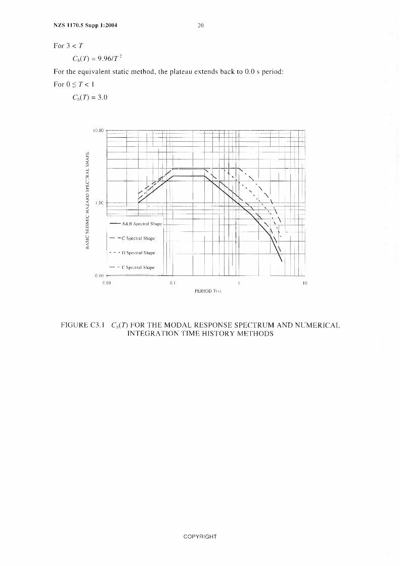
The spectral shape factors, Ch(T), are defined differently for the equivalent static method and for the modal response spectrum (MRS) or numerical integration time history (NITH) methods. For the modal response spectrum and numerical integration time history methods, Ch(T) is defined in terms of smooth approximations to the shapes of the estimated hazard spectra for the various site classes (Figure C3.1), as given in equation form later in this section. For the equivalent static method, the coefficients for periods less than 0.4 s are taken as the 0.4 s values over the whole period band 0.0 s to 0.4 s (Figure C3.2). This is to overcome problems with estimating short fundamental periods accurately.
The corner period Tc at the long-period end of the plateau at the peak of the spectrum depends on the site class. For site classes A (strong-rock), B (rock) and C (shallow-soil), the corner period Tc is 0.3 s for the MRS and NITH methods. The corner periods are 0.56 s for site class D (deep or soft soil) and 1.0 s for site class E (very soft soil).
The basis for the spectral shapes are discussed in McVerry (Refs. 17 and 18).
COPYRIGHT

NZS 1170.5 Supp 1:2004 18
A single spectral shape for all New Zealand rock sites has been selected for simplicity in this Standard. The data used to derive the rock spectra given by the attenuation model are dominated by records from class B rock sites.
Earthquake records from sites with about] 0 m or more of very low velocity soils (shear-wave velocities Vs < 150 m/s) were excluded from the analyses in developing the attenuation models, so the class D amplifications may be inappropriate for such sites. In recognition that such sites often show very strong motions in the long-period band, the corner period for this site class has been increased to 1 s. This selection results in a scaling up of the long-period branches (beyond I~) for this site class by a ratio of! .55 with respect to class D, typical of the ratio of the long-period site-factors for classes D and E in the NEHRP 2000 code (BSSC, Ref. 13). Initially, consideration was gi ven to scaling up the plateau of the spectrum from that for class D using factors similar to those in NEHRP 2000, but comparison with spectra of recorded motions suggested that records from class E sites generally exhibited significant amplification with respect to class D sites only in the longer-period ranges. Accordingly, the amplitude of the short-period plateau and of peak ground accelerations has been taken as the same for classes D and E.
Spectra shapes in equation form
To assist construction of spreadsheets, the spectral shape factors given in Table 3.1 and Figures 3,1 and 3.2 are expressed here in equation form.
Class A strong rock and Class Brock
The values for the modal response spectrum (MRS) method and for the numerical integration time history (NIT H) method are given by:
Ch(O) = J.O
For 0 < T < 0.1
Ch(T) 1.0 + 1.35 (TIO.l)
For 0.1 < T < 0.3
Ch(T) 2.35
For 0.3 T 1.5
Ch(T) = 1.60 (O.SIT) 0.75
For I.S < T 3
Chef) = 1.OSIT
For 3 < T
For the equivalent static method, the coefficients in the short period range up to 0.4 s are taken to be the 0.4 s values of the MRS and NITH methods:
For 0 :s T < 0.4
Ch(T) = 1.89
Class C shallow soH
The values for the MRS and NITH methods are given by:
CIlO) = 1.33
For 0 < T < 0.1
CI,(T) = 1.33 + 1.60 (TIO.I)
For O. 1 < T < 0.3
COPYRIGHT

Ch(T) = 2.93
For 0.3:S T 1.5
Ch(T) = 2.0 (0.5IT) 0.75
For 1.5 < T < 3
Ch(T) = I.321T
For 3 < T
19 NZS 1170.5 Supp 1 :2004
Again, the coefficients for the equivalent static method in the short period range up to 0.4 s are taken to be the 0.4 s values of the MRS and NITH methods:
For 0 T < 0.4
Ch(T) = 2.36
Class D deep or soft soil
The values for the MRS and NITH methods are given by:
Ch(O) = 1.12
For 0 < T < 0.1
Ch(T) 1.12 + 1.88 (TIO.1)
For 0.] T < 0.56
Ch(T) 3.0
For 0.56 T:S 1.5
Ch(T) = 2.4 ( 0.75/T)
For 1.5 < T 3
Ch(T) = 2.141T
For 3 < T
(\(1) 6.421T 2
For the equivalent static method, the plateau extends back to 0.0 s period:
For 0 T < 0.56
Ch(T) 3.0
Class E very soft soil
The values for the MRS and NITH methods are gi ven by:
Ch(O) = 1.12
0< T < 0.1
Ch(T) = 1.12 + 1.88 (TIO.I)
For 0.1 T < 1
Ch(T) 3.0
For 1 :s T 1.5
Chcn = 3.0 IT
For 1.5 < T 3
COPYRIGHT
NZS 1170.5 Supp 1:2004 20
For 3 < T
Ch(T) = 9.96/T2
For the equivalent static method, the plateau extends back to 0.0 s period:
For 0 :s T < 1
;.w 0--< :r: V)
~ ~
u W Q.. V)
0 Ct! -< :--.: -< :r: U
~ Vl
i: Vl
S:! Vl
< ::::l
10.00
,
:
I: b11,t
1.00
v; r/ ~vv V
V V-! ! I
I
- ,t..&B Spectral Shape
- - -
0.10
(J.OI
~
Spectral Shape
i I
0.1
I
I', 1'1 "-
~
i
!
I
1
PERIOD T(s}
: 1 I 1 i
:
I !
i
r-." I
1'r-- " 'K ~ " "\ i'r-.. N l' .~
I , .... " , \
" \
"-'" "- "
1\
'\.' \
'" 1\\ \
\~
I I! I i
I .
I I
I !
11.1 •.
I
I I
i
10
FIGURE C3.1 Ch(n FOR THE MODAL RESPONSE SPECTRUM AND NUMERICAL INTEGRATION TIME HISTOR YMETHODS
COPYRIGHT

21 NZS 1170.5 Supp 1 :2004
1000 ,"
"~ - ---
I
I
I I I I
,-:-.
i I I r ...... , I r== r== -r 1-' l' i " I ,
I
1""'-1"- ii' ' I
f',f'-.., '\
I i'-, I " ,
" ,: " ' \ "'- , \
........ \. , \ ----
"" ...... ' \
cJ Z W..l
~ 11: UJ
8 1.00
0 0::
"-'\ "- \ \ « N «
L '\.\ ' -~
\\ ' "-~
J:
~ :2 l/l
-A& BRock
\' -- -C Shallow Soil I
I
\ I
- - - D Deep or Soft Soil I I
- - E Very Sort Soil I !
W l/l
~ l/l « o::l
0.10
0_01 0.1 10
PERIOD T(s)
FIGURE C3.2 Chcn FOR THE EQUIV ALENT STATIC METHOD
C3.I.3 Site subsoil class
Site class definitions consider both soil type and depth, which determine a site's dynamic stiffness and period. These in turn are major factors in determining the site's dynamic response characteri stics, along with the impedance contrast wi th u nderl yi ng rock, the damping of the soil, and its degree of nonlinearity.
Consideration of the depth of soil was included in NZS 4203, but this approach to the definition of site classes differs from current codes in the United States, such as the 1997 UBC (lCBO, Ref. 16) and the 2000 IBC (lCC, Ref. 15) codes. The U.S. codes are based on the average shear-wave velocity to 30 m depth, without consideration of the depth to rock. Depths of material enter site descriptions for U.S. codes only for treatment of soft clay and other soils that are required to be subjected to special studies for some zone factor values.
The basic parameter for site classification in this Standard is the low-amplitude site period, recommended to be taken as four times the estimated travel-time of shear waves from the surface to rock when it has not been measured directly. The site-period approach recognizes that deep deposits of stiff or dense soils or gravels exhibit long-period site response characteristics markedly different from those shown by deposits of only a few tens of metres of the same material. The U.S. approach of placing deep stiff sites in a "stiff soil" class with relati vely short -period spectral characteri stics is non -conservati ve at medi um-to-Iong spectral periods.
The defini tions of the si te cl asses are generally descri pti ve rather than requiri ng know ledge of site properties, because these are not generally available in New Zealand. The soil descriptions and associated properties used in the site subsoil class definitions correspond to those gi ven by the New Zealand Geomechanics Society (Ref. 21).
The site subsoil classes are similar to those of the New Zealand Standard NZS 4203, but with some important modifications in the definition of classes for rock and very soft soils.
COPYRIGHT

NZS J 170.5 Supp 1:2004 22
Site subsoil class B is restricted to rock, apart from allowing a thin veneer of highlyweathered or completely-weathered rock or soil of no more than 3 m thickness. Its counterpart in NZS 4203 consisted of combined rock and some very stiff or dense soil sites in a single site class. During the derivation of the response spectrum attenuation model used for the New Zealand hazard studies performed for the development of this Standard, it was found that the spectra and peak ground accelerations for the soil sites that were formerly combined with rock sites were statistically significantly different from rock spectra, and similar to spectra from other shallow soil sites (Zhao et al., Ref. 32, McVerry et al. Ref. 19). In recent studies at the University of California, Berkeley, Rodriguez-Marek et al. (Refs. 25, 26, 27) have demonstrated similar behaviour in spectra from the 1989 Loma Prieta and 1994 Northridge earthquakes.
The rock class definition excludes sites where rock is underlain by materials of substantially lower compressive strength or shear-wave velocity. The site class In these situations should be determined as that appropriate for the weaker or lower-velocity material.
An unconfined compressive strength of 1 MPa is assigned as the boundary between rock and soil. This boundary is consistent with that of the New Zealand Geomechanics Society (Ref. 21). The minimum 360 mls shear-wave velocity allowed for the rock class corresponds to an approximate metric conversion of the 1200 ftls boundary between veryldense soil/soft rock and stiff soil in the U.S. classifications in the NEHRP 1997 (Ref. 12), UBC 1997 (Ref. 16 and IBC 2000 (Ref. 15) codes. Rock requires both a strength of at least 1 MPa and a shear-wave velocity of greater than 360 m/s. Very stiff or very dense soils or gravels that may have shear-wave velocities in this range are excluded on the basis of the studies referred to earlier.
Site subsoil class C shallow soil consists of the intermediate soil sites of NZS 4203, with the addition of the very stiff and dense soil sites that were previously associated with rock sites in NZS 4203. Very soft soil sites have been excluded. With the exclusion of soil sites from the rock class, the name has been changed from Intermediate to Shallow soil sites, to more accurately reflect the character of this modified class.
Site subsoil class D deep or soft soil sites is very similar to category (c) flexible or deep soil sites of NZS 4203, apart from the exclusion of some sites with very low shear-wave velocities that are included in Site Subsoil Class E Very Soft Soil Sites. Table 3.2 has been carried over without change from NZS 4203.
The importance of the combination of depth and average shear-wave velocity in determining the character of soil-site spectra was verified in the development of the New Zealand response spectrum model, and in the study of Rodrfguez-Marek et al (Refs. 26, 27). In the early stages of the development of the New Zealand attenuation model, Class D sites with estimated average shear-wave velocities less than 200 m/s in the top 30 m ("soft" sites) were distinguished from those with higher average shear-wave velocities that fell into this class because of their depth ("deep" sites). Statistical analysis of differences between the modelled and recorded spectra showed that the spectra for the "deep" sites fitted better with those for the "soft" sites than with those for the Class C sites (i.e. shallow, generally stiff, soil sites), and the joint "deep or soft" classification was retained.
A new site subsoil class E very soft soil sites has been introduced. This class is for sites with about 10 metres depth or more of materials with shear-wave velocities lower than 150 m/s. Records of earthquake motions from this category were excluded in the development of the New Zealand response spectrum attenuation model. Such sites are often associated with amplifications for low-to-moderate levels of earthquake shaking that are considerably greater than those assigned to classes C and D. Often low shear-wave velocities are correlated with low strengths that may lead to highly non-linear behaviour in strong shaking. On the other hand, high amplification may persist to strong levels of motion for high-plasticity clay sites. As guidance to the types of sites that fall into class E, examples of class E sites from among the sites of the New Zealand strong-motion earthquake accelerograph network are: Gisborne
COPYRIGHT

23 NZS 1170.5 Supp 1:2004
Post Office, Napier Civil Defence on the reclamation from the 1931 earthquake, Hastings Civil Defence Headquarters, Wairoa Telephone Exchange, St Kilda Fire Station and St Clair Telephone Exchange in Dunedin, Opotiki, Tolaga Bay Post Office, Wainuiomata Bush Fire Force, Haast DOC building, Reporoa Dairy Factory, Edgecumbe substation, and Porirua Library. Parts of Christchurch are also likely to fit this site class (e.g. Berrill et al., Ref. 9).
When the foundation materials consist of saturated loose sands, silts, combinations of sand and silt or uncontrolled fill, account should be taken of the potential for liquefaction. There was no corresponding class in NZS 4203. The combination of high-amplification and lowstrength makes codification of their expected spectra difficult, but as they occur reasonably commonly in New Zealand coastal towns and cities, provision of default spectra in the Standard was thought appropriate. Many of these sites will fit the "Special Studies" categories of U.S. codes.
The detrimental effects of localized soft soil conditions on the response of structures to earthquakes have long been recognized. It is now recognized that these effects are quite complex, depending on impedance contrasts, resonant frequencies, non-linear material characteristics, basin shape, differential settlement and other factors. The descriptions in the text are therefore only a simple guide to a complex problem. Where there are severe stiffness contrasts, the designer should be wary of the effects of resonance. However where the change is gradual, amplification effects may be minimal. Tal1 structures or those with a long natural period, may be shaken more strongly than others due to variations in the profile at greater depth.
Site classification for piled foundations
There are difficulties in assigning an appropriate site class for structures founded on piles that extend through soil to a stronger, less flexible layer. In general, the classification of a site will be dependent on the surface soils even where vertical piles or piers extend down to a harder underlying stratum, in that it is these that drive the structural response. However, with raking piles or with stubby vertical piles or piers, the possible adverse effects of the stiffer foundations should be considered. Also, there may be situations with sleeved piles and specifically-designed separation of the structure above the basement from the surrounding soil, as occurs in some types of seismic isolation for example, where the structure is clearly likely to be subjected to the motions in the underlying stratum rather than those of the surface soils.
Assessment of low amplitude site period
The low amplitude natural period of a site may be determined from the quarter-wavelength approximation (4hIV,,), where the depth h in metres and shear wave velocity Vs in mls are known, or from a Nakamura type study.
The Nakamura method is a relatively cheap and simple method of detecting possible amplification or resonance periods in a layer, (Nakamura, Ref. 20). Where the site geometry is simple and horizontal, comprising a softer layer or layers with an abrupt interface to a firmer layer, the results are quite reliable, however this is not the case with complex geometry, or complex or variable interfaces.
Standards for evaluation of geotechnical properties
Standard Penetration Test (SPT) N-values may be determined according to ASTM D 1586 (Ref. 2) or AS 1289 (Ref. 5).
Undrained shear strengths may be determined according to ASTM D2166 (Ref. 3) or ASTM D2850 (Ref. 4) or AS 1289 (Ref. 5).
COPYRIGHT

NZS 1170.5 Suppl:2004 24
C3.1.3.7 Evaluation of periods for layered sites
Where a site consists of several types of material, the period may be estimated by summing the contributions to the natural period of each layer. The procedure described for the evaluation of the periods of layered sites corresponds to the assumption that the natural period is proportional to the shear-wave travel time through the layers, and that the response is one-dimensi onal in nature.
C3.1.4 Hazard factor
The hazard factor Z has been derived as 0.5 times the magnitude-weighted (ldriss, Ref. 14) 5% damped response spectrum acceleration for 0.5 s period for site class C (sha] low soil) that has a return period of 500 years. It corresponds to the value in g of the peak ground acceleration (corresponding to 0.0 s period) for site classes A and B (rock) for R = l. The range of Z has been limited by a lower bound of 0.13. The Z-values have been spatially smoothed over a distance of 10 from the values resulting directly from the hazard analysis.
The selection of the period of 0.5 s to normalize the hazard spectra is a change from New Zealand Standard NZS 4203, which used 0.2 s. The unusual selection of the mid-period value of 0.5 s for the normalization provided sufficiently small variations over the country between the code spectra and the 500-year magnitude-weighted spectra of the hazard study to allow spectra to be defined from the values at only one normalization period, rather than two as in recent U.S. codes (UBC, 1997, Ref. 16, NEHRP, 2000, Ref. 13, and IBC, 2000, Ref. 15).
Maxinlum considered ulotions
A structure should have a small margin against collapse in the most severe earthquake shaking to which it is likely to be subjected. The maximum considered motions assumed to represent this level of shaking for normal-use buildings in the development of this Standard have generally been taken as those with a 2% probability of exceedance in 50 years, or a return period of approximately 2500 years. However, the spectrum for the maximum considered motions is not required to exceed that corresponding to a ZRu product of 0.7 and the 2500-year hazard factor must exceed the value of 0.2 (i.e. the minimum allowable value of Z of 0.13 scaled up by the margin against collapse of 1.5 assumed in deriving ULS loads). These values correspond to deterministic bounds associated with the maximum considered motions in the highest and lowest seismicity regions of New Zealand, as explained below.
Maximum required ZRu product
For the highest seismicity regions, the design motions are scaled down from those corresponding to a specific event, namely a magnitude 8.1 Alpine Fault earthquake. The maximum ZRu value of 0.7 corresponds to estimated 84-percentile motions adjacent to the fault divided by an assumed margin of safety of 1.5 likely to result from applying code design procedures. Near-fault motions from rupture of the Alpine Fault are judged to be the strongest earthquake motions likely to be experienced in New Zealand. An 84% probability of nonexceedance when such an earthquake occurs is a value that is applied common Iy in determining maximum considered motions.
~1inimum Z value
The minimum allowable value of Z 0.13 has been set to ensure a margin against collapse in earthquakes that may occur in low seismic areas without identification of pre-existing surface fault traces. The selection of a mini mum Z-val ue departs from the probabilistic basis used for deriving the site hazard spectra. imposing instead a deterministically defined minimum level of earthquake motion that any normal-use (i.e. R 1) structure in New Zealand should be specifical1y designed to survive.
COPYRIGHT

25 NZS 1170.5 Supp 1 :2004
The value of 0.13 has been established as follows:
(a) Assume a margin against collapse in major earthquake shaking implied by the use of typical design procedures of 1.5, as assumed in the U.S. derivation of loads in IBC 2000 (Ref. 15).
(b) Assume that a structure anywhere in the country is likely to be subjected to, and should be able to survive earthquake motions at least as strong as those corresponding to the 84-percentile motions in a magnitude 6.5 normal-faulting earthquake at a closest distance of 20 km from the site. This magnitude of the earthquake has been selected because it is about the largest that is likely to occur in the lower-seismicity regions of New Zealand without identification of pre-existing surface traces. A normal-faulting mechanism has been assumed, because this is the predominant mechanism in the low hazard areas of New Zealand where this lower-bound event is likely to govern the design motions. The 84 percentile level is generally taken as an upper-bound level for deterministic scenario spectra.
(c) To be consistent with the treatment of the hazard estimates in the development of the code spectra, apply the Idriss magnitude-scaling factor of 0.83 that applies for a magnitude 6.5 earthquake for periods of 0.5 s and less.
(d) Assume that no margin against collapse is required for the most severe earthquake shaking.
(e) Then the mlmmum allowable value of Z is approximately the largest value of 0.5*0.83*SA(0.5 s)Il.5Ch(0.5 s) for any of the site conditions, where SA(0.5 s) is the estimated 84 percentile acceleration at 0.5 s period for the magnitude 6.5 event at 20 km distance, and Ch(D is the spectral shape factors for the same site conditions. The value of SA(0.5 s) = 0.47 g for class C shallow soil conditions is found to govern, producing a minimum allowable Z-factor of 0.13.
C3.1.S Return period factor
The return period factor R is required to scale spectra to return periods other than 500 years, as required for the serviceability limit state and for various combinations of structural importance level and reference period as given in Tables 3.1 and 3.2 of Part O. Values for the return period factor have been derived by drawing a representative line through the hazard curves (response spectrum acceleration as a function of return period) normalized by the 500-year values for various structural periods for a range of locations, as shown in Figure C3.3. For simplicity, the R factor is applied everywhere, although a case could be made for retaining an RZ product 0.13 in low-hazard locations until the hazard estimate for the required return period exceeds this product.
COPYRIGHT

NZS 1170.5 Supp 1:2004 26
2.8
2.0
0 2.4 1=
-< ;::::: v:
>n
8 1.8
1.6
IA
1.2
0.8
0.6
0.4
0.2
0
10
SA (0.5 s) VARIATION WITH RETURN PERIOD
100 1000
RETURN PERIOD (YRS)
. - - - - - .l\uckland
- Wellingtoll
- - - - ChriMchurch
- - - - Dunedin
-'OOra
- /\dopteu R-fartor values
10000
FIGURE C3.3 COMPARISON OF PROPOSED R-FACTORS FOR NEW ZEALAND WITH HAZARD CURVES FOR 0_5 s SPECTRAL ACCELERATIONS
C3.1.6 Near-fault factor
The strength and duration of earthquake ground-motions within a few kilometres of the earthquake rupture surface are strongly influenced by a number of near-fault effects producing features that are not generally present in motions at sites more distant from the rupture. Such effects are not accounted for in the models used for deriving the hazard estimates on which the spectral shapes and seismicity factor maps of this Standard are based, but are systematic effects that are amenable to modelling. Their neglect may lead to considerable underestimation of the strength of motions at near-fault locations.
Near-fault features include directivity and polarisation effects related to propagation from a moving rupture (Somerville et al., Ref. 28); "fault-fling" i.e. the growth of the permanent displacement associated with the fault offset (Abrahamson, Ref. 6); hanging wall effects associated with dip-slip faults (Abrahamson and Somerville, Ref. 7); large vertical accelerations, with near-source vertical spectra often exceeding the horizontal spectra at short periods (Niazi and Bozorgnia, Ref. 23; Bozorgnia and Niazi, Ref. 11); and trapping of energy when the faulting penetrates into lower-velocity surface layers. These features are responsible for large variations of ground shaking for equivalent ground conditions and distances from the fault. Forward-directivity pulses produce large ground velocities, typicaJly 1.0-1.5 mis, and displacements that are likely to generate large amplitude inelastic response in structures experiencing them.
Of these features, convenient models for adjusting estimates from standard attenuation models are available for directivity and polarisation effects (Somerville et aI., Ref. 28), and for hanging wall effects (Abrahamson and Somerville, Ref. 7). "Fault-fling" models are in development (Abrahamson, Ref. 6). but not yet suitable for routine use.
COPYRIGHT

27 NZS 1170.5 SI1PP 1 :2004
Modelling of near-fault effects in terms of their effects on code hazard coefficients is important only for faults that make dominant contributions to the hazard at return periods of interest for design. Only the most active major faults in New Zealand have recurrence intervals short enough and magnitudes large enough that they dominate hazard estimates for return periods of a few hundred to a few thousand years that are of interest for design. For design for short return periods of 200 years or less, near-fault factors can be ignored, as no New Zealand faults have average recurrence intervals this short for earthquakes of magnitude 7.0 or greater.
The Californian Category A fault criteria (Petersen et aI., Ref. 24) used in the 1997 UBC (lCBO, Ref. 16) provide a convenient specification of those faults to be subject to the nearfault factors. Class A faults are those assessed as capable of producing earthquakes of magnitudes of 7.0 or greater, and having slip rates of 5 mm/year or greater. When these criteria are applied to the preferred estimates of New Zealand fault parameters, rather than upper-bound magnitude or slip-rate estimates, the selected faults as limited to New Zealand's most active major strike-slip faults, as listed in Table 3.6. No normal or reverse faults qualify.
The near-fault factors of Clause 3.1.6 model two systematic near-source effects: forwarddirectivity and polarisation of the long-period motions in the near-source region. As no dipslip faults satisfy the criteria for consideration, modelling of hanging-wall effects can be neglected. The derivation of the values given for the near-fault factor in Clause 3.1.6 may be found in McVerry (Ref.18), based on simple models developed by Somerville et al. (Ref. 28).
Near-fault motions are usually strongly polarised, with the medium- to long-period pulses being stronger in the direction perpendicular to the strike of the fault. In the case of a strikeslip earthquake, the enhanced strength of the fault-normal component is counter to intuition, which suggests that the motion along the strike in the same direction as the fault displacement should be greater. This is true of the permanent offset component of the displacement, but not for the dynamic pu I ses that control the response spectra. For points close to the fault lying virtually along the fault axis, the radiation patterns for strike-slip faulting show a maximum for the tangential component of motion, corresponding to motion perpendicular to the fault, but a minimum for the radial component, corresponding to motion parallel to the fault. The relative strength of the fault-normal component for sites in the direction of rupture propagation increases with a moving fault-rupture compared to that for a point source. For dip-slip earthquakes, the polarisation of the directivity pulse and the fault displacement are aligned.
The combination of the directivity and polarisation effects results in the forward-directivity strike-normal ground motion above 0.5 s being approximately double the average acceleration predicted by attenuation relationships that treat directivity as part of the randomness. The strike-parallel ground motion is approximately the average given by standard attenuation relationships that ignore these effects.
Large enhanced directivity will apply only for some epicentres, so it would be very conservative to apply maximum directivity effects for all earthquakes. This is taken into account by assuming that about one-third of earthquakes have large directivity and about two-thirds have near-neutral directivity effects.
Somerville et aI., (Ref. 28) highlight that near-fault directivity and polarization effects can not be adequately represented by spectral modification factors alone. Small modifications to the time history near-fault pulse that have little effect on the response spectrum could have marked effects on the response of non-linear systems. Dependence of the non-linear response on the acceleration history used, even when the response spectra are simi lar, is a well-known effect but seems to be accentuated when the time history contains a large pulse.
As a result, for long-period structures at locations where directivity effects could be significant, it is recommended that time history analysis is carried out. It should use some acceleration histories that include directivity effects, as a realistic directivity pulse cannot be
COPYRIGHT

NZS 1170.5 Supp 1 :2004 28
introduced in a record where it does not already exist by simply scaling to match a response spectrum. Care should also be taken with respect to the orientation of the record as strikenorma] and strike-parallel components should not be realistically interchanged. Also, it is important to include records with neutral and/or backward directivity, as their greater durations than for forward-directivity motions may be important for non-linear response quantities that are sensitive to duration. To be consistent with the assumptions made in the derivation of the near-fault factors, about one-third of the records in the suite of records selected should possess forward-directi vity effects, while the others should have neutral-or backwards-directivity properties. Somerville et a1. (Ref. 28) list the values of the parameters relevant for near-source effects to assist in this selection of appropriate records.
C3.2 SITE HAZARD SPECTRA FOR VERTICAL LOADING
The factor of 0.7 used to determine vertical spectra from horizontal spectra is an approxilnation to the factor of that has been used for many years in the Uniform Building Code, based on the pioneering work on spectral shapes by Newmark and Hall (Ref. 22). At periods of about 0.5 s and greater, the ratio of the vertical to horizontal spectrum usually falls below this value (Niazi and Bozorgnia, Ref. 23). However, in the near-source region, the high-frequency content of vertical motions is often very strong, leading to peak ground accelerations and spectra at short periods that may exceed the horizontal values (Niazi and Bozorgnia, Ref. 23); Bozorgnia and Niazi, (Ref. 11); Ambraseys and Simpson (Ref. 8)). At near-source locations, the short-period part of the vertical spectrum may equal or exceed the horizontal spectrum. At locations where the seismic hazard is dominated by a fault at a distance of less than 10 km, it may be more appropriate to assume that the vertical spectrum equals the horizontal spectrum for periods of 0.3 s and less.
REFERENCES
1. NZS 4203: 1992, 'Code of Practice for General Structural Design and Design Loadings for Buildings', Standards New Zealand, 1992.
2. ASTM D 1586-99, 'Standard Test Method for Penetration Test and Split-Barrel Sampling of Soils', American Society for Testing and Materials, West Conshohocken, Pennsylvania, 1999.
3. ASTM D2166-00, 'Standard Test Method for Unconfined Compressive Strength of Cohesive Soil', ASTM International Standards World{;vide, 2000.
4. ASTM D2850-95, 'Standard Test Method for Unconsolidated-undrained Triaxial Compression Test on Cohesive Soils', ASTM International Standards Worldwide, 1995.
5. AS 1289-2000, 'Methods of Testing Soils for Engineering Purposes', Standards Australia, 2000.
6. ABRAHAMSON, N.A., 'Incorporating Effects of Near-Fault Tectonic Deformation into Design Ground Motions', MCEER Webcast http://civil.eng.buffalo.edu/webcast/abrahamson/, 2001.
7. ABRAHAMSON, N.A., and SOMERVILLE. P.G., 'Effects of the Hanging Wall and Footwall on Ground Motions Recorded during the Northridge Earthquake', Bulletin the Seismological Society of America, 86(1 1996, pp. S93-99.
8. AMBRASEYS, N.N., and SIMPSON, K.A., 'Prediction of Vertical Response Spectra in Europe', Earthquake Engineering and Structural Dynamics, Vol. 25, 1996, pp. 401-412.
9. BERRILL, J.B., DAVIS, R.O., and McCAHON, LF., 'Christchurch Seismic Hazard Pilot Study', Bulletin the Nea: Zealand National Society for Earthquake Engineering, 26(1), 1993, pp. 14-27.
COPYRIGHT

29 NZS 1170.5 Supp 1:2004
10. BERTERO, V.V., MAHIN, S.A., and HERRERA, R.A., 'Aseismic Design Implications of Near-Fault San Fernando Earthquake Records', Earthquake Engineering and Structural Dynamics, 6, 1978, pp. 31-42.
] 1. BOZORGNIA, Y., and NIAZI, M., 'Distance Scaling of Vertical and Horizontal Response Spectra of the Loma Prieta Earthquake', Earthquake Engineering and Structural Dynamics, 1993, pp. 695-707.
12. BUILDING SEISMIC SAFETY COUNCIL (BSSC) (1998). 1997 Edition 'NEHRP Recommended Provisions for New Buildings and Other Structures', Part I (Provisions) and Part II (Commentary), FEMA 302/303, Washington DC.
t3. BUILDING SEISMIC SAFETY COUNCIL (BSSC) (2000). 'The 2000 NEHRP Recommended Provisions for Seismic Regulations for New Buildings and Other Structures', Part I (Provisions) and Part II (Commentary), FEMA 368/369, Washington DC.
14. IDRISS, I.M., 'Evaluating Seismic Risk in Engineering Practice', Proceedings of the I Ith International COl~{erence of Soil Mechanic·; and Foundation Engineering, 1, San Francisco, 1985. pp. 255-320.
15. INTERNATIONAL CODE COUNCIL, INC. (ICC) (2000), International Building Code, Building Officials and Code Administrators, Inc., International Conference q{ Building OJlzcials, and Southern Building Code Congress International, Inc., Birmingham, AL, USA.
16. INTERNATIONAL CONFERENCE OF BUILDING OFFICIALS (ICBO) (l997), Uniform Building Code, Whittier, CA, USA.
17. McVERRY, G.H., (2003), 'From Hazard Maps to Code Spectra for New Zealand', Paper 34, 2003 Pacijk COl~{erence on Earthquake Engineering, Christchurch, New Zealand.
18. McVERRY, G.H. (in prep. 2005), 'Near-fault factors for New Zealand code spectra'.
19. McVERRY, G.H., ZHAO, 1.X., ABRAHAMSON, N.A., and SOMERVILLE, P.G., 'Crustal and Subduction Zone Attenuation Relations for New Zealand Earthquakes', Paper 1834, Proceedings J 2th World Conference on Earthquake Engineering, Auckland New Zealand, 2000.
20. NAKAMURA, Y., 'A Method for Dynamic Characteristics Estimation of Subsurface using Microtremor on the Ground Surface'. Quarterly Report of Railway Technical Report In'),titute of Japan, 30(1), 1989. pp. 25-33.
21. NEW ZEALAND GEOMECHANICS SOCIETY (1988). 'Guidelines for the Field Description of Soils and Rocks in Engineering Use'.
22. NEWMARK, N.M., and HALL, W.J., (1982), 'Earthquake Spectra and Design'. Earthquake Engineering Research Institute.
23. NIAZI, M., and BOZORGNIA, Y., 'Behaviour of Near-source Vertical and Horizontal Response Spectra at SMART -1 Array', Earthquake Engineering and Structural Dynamics, 21, 1992, pp. 37-50.
24. PETERSEN, M.D., TOPPOZADA, T.R., CAO, T., CRAMER, C.H., REICHLE, M.S., and BRYANT, W.A., 'Active Fault Near-source Zones Within and Bordering the State of California for the 1997 Uniform Building Code', Earthquake Spectra, 16(1), 2000, pp.69-83.
25. RODRIGUEZ-MAREK, A., BRAY, J.D., and ABRAHAMSON, N., 'Task 3: Characterization of Site Response General Site Categories'. PEER Report 199103, Pacijk Earthquake Engineering Research Center, College of Engineering, University of California, Berkeley, 1999.
COPYRIGHT

NZS 1170.5 Supp 1:2004 30
26. RODRIGUEZ-MAREK, A., BRAY, J.D., and ABRAHAMSON, N., 'A Geotechnical Seismic Site Response Eva1uation Procedure, Paper 1590', Proceedings 12th World Conference on Earthquake Engineering, Auckland New Zealand, 2000.
27. RODRIGUEZ-MAREK, A., BRAY, J.D., and ABRAHAMSON, N., 'An Empirically Based Geotechnical Seismic Site Response Procedure', Earthquake Spectra, 17(1), 2001, pp.65-87.
28. SOMERVILLE, P.G., SMITH, N.F., GRAVES, R.W., and ABRAHAMSON, N.A., 'Modification of Empirical Strong Ground Motion Attenuation Relations to Include the Ampl itude and Duration Effects of Rupture Directivity', Seismological Research Letters, 68(1), 1997, pp. 199-222.
29. STIRLING, M.W., 'New National Probabilistic Seismic Hazard Maps for New Zealand', Paper 2362, Proceedings J 2th World Conference on Earthquake Engineering, Auckland New Zealand, 2000.
30. STIRLING, M., McVERRY, G., BERRYMAN, K., McGINTY, P., VILLAMOR, P., VAN DISSEN, R., DOWRICK, D., COUSINS, J., and SUTHERLAND, R., 'Probabilistic Seismic Hazard Assessment of New Zealand: New Active Fault Data, Seismicity Data, Attenuation Relationships and Methods', Client Report 2000153, prepared for Earthquake Commission Research Foundation, Institute qf Geological & Nuclear Sciences Ltd, Gracefield New Zealand, 2000.
31. STIRLING, M.W., McVERRY, G.H., and BERRYMAN, K.R., 'A New Seismic Hazard Model for New Zealand', Bulletin of the Seismological Society of America, 92(5), pp. 1878-1903, 2002.
32. ZHAO, .LX., DOWRICK, D.1., and McVERRY, G.H., 'Attenuation of Peak Ground Accelerations in New Zealand Earthquakes', Bulletin (~f the New Zealand National Society for Earthquake Engineering, 30(2), 1997, pp. ) 33-158.
COPYRIGHT

31 NZS 1170.5 Supp 1:2004
SECTION C4 STRUCTURAL CHARACTERISTICS
C4.1 PERIOD OF VIBRA TION
C4.1.1 General
Tests on ful1-size buildings show that it is difficult to accurately calculate their dynamic characteristics (Ellis, Ref. 6). The proper choice of material and member properties for the calculation of stiffness is important. Guidance in this choice should be sought in the material Standards.
In calculating the periods of vibration, the influence of the flexibility of the supporting soils should be considered. Ignoring foundation flexibility will generally lead to a conservative assessment of the seismic forces, but it is likely to result in a low estimate of the seismic deformations. Particular caution is required where different foundation types or supporting soils occur under the same building. In such cases the differing foundation stiffnesses may have a direct influence on the distribution of seismic forces in the structure.
C4.1.2 Period detennination for the equivalent static method
C4.1.2.1 Rayleigh method
The Rayleigh method is widely recognized (e.g. EC8, Ref. 5, FEMA, Ref. 7, UBC, Ref. 12), as a method for predicting the fundamental period of vibration of a structure since it is based on methods of structural dynamics and utiJizes the actual material and member properties to form a structural stiffness matrix. The method also determines the modal shape and can be used to determine the second and third natural periods and their mode shapes. Nevertheless, there are also a number of empirical methods that have been suggested for use in determining the fundamental natural period of structures. These methods are approximate only since they do not take account of the actual shape and properties of each structure. Some of these methods are given below.
These approximate methods do not use material and section properties appropriate to the limit state under consideration. Hence it should be noted that these approximate methods can be used for initial estimates in preliminary design, or in structural checking.
C4.1.2.2 Empirical method A (R£~f. 5)
TI 1.0kt hn 0.75
TI I.25kt hn 0.75
where kt 0.075
= O~ 11
0.06
for the serviceability limit state
for the ultimate limit state
for moment-resisting concrete frames
for moment-resisting steel frames
for eccentrically braced steel frames
for aU other frame structures
hn = height in m from the base of the structure to the uppermost seismic weight or mass.
COPYRIGHT

NZS 11 70.5 Supp 1 :2004 32
C4.1.2.3 Empirical method B (Ref 5)
Alternati vely, the value kt for use in Clause C4.1.2. I for structures with concrete shear walls may be taken as:
0.075 =
where
and
Ac total effective area of the shear walls in the fjrst storey in the building, in m2
Ai = effective cross-sectional area of shear wall in the first storey of the building, in m2
hn = as in Clause C4.1 .2.2
= length of shear wall in the first storey in the direction parallel to the applied forces, in m
with the restriction that€w/hn shall not exceed 0.9.
C4.1.2.4 Empirical method C (Ref 5)
The estimation of TI may be made using the following expression:
=
where
d
21d
the lateral elastic displacement of the top of the building, in m, due to gravity loads applied in the horizontal direction.
C4.2 SEISMIC WEIGHT AND SEISMIC MASS
The live load contribution to the seismic weight is an arbitrary point-in-time value and is the same for both limit states.
C4.3 STRUCTURAL DUCTILITY FACTOR
The preferred source of the structural ductility factor for a given seismic-resisting system is the relevant limit state format material Standard, written specifically for compatibility with this Standard by being compliant with Appendix D. The choice of the structural ductility factor carries with it requirements for design and detailing of the system and these requirements must be met to ensure that the anticipated level of inelastic demand can be reliably sustained.
It is recognized that, pending publication of all material Standards in limit state format, guidance on structural ductility factors and material design requirements will need to be sought from existing material Standards or other published sources. This factor may be varied by the relevant source document and must be applied in conjunction with the appropriate design and detailing requirements from that source.
COPYRIGHT

NZS 1170.5 Supp 1 :2004
Determination of structural ductility factor
(a) With brittle and nominally ductile structures the inelastic deformation required is such that the normal detailing rules are usually sufficient to enable the required material strain levels to be sustained. Exceptions to this arise in multi-storey frames where a column sway mechanism limits the lateral strength. For this reason material Standards Ii mit the use of certain structural forms for brittle and nominally ductile structures.
(b) Ducti Ie structures
(i) For regular structures, as defined in Clause 4.5 and modified in the appropriate material Standard, the structural ductility factor, fl, can be used as a measure of the material strains required in the plastic zones. Hence for these structures, Ii can be used to select the required level detailing in the potential inelastic zones.
(ii) For structures which do not satisfy b(i) above, the material strains in the critical inelastic zones need to be assessed to ensure the level of detailing is adequate to sustain these strains. Appendix C contains further information on the analysis of critical material strains.
(c) The material strain limits are given in the appropriate material Standard. Further details are given in Appendix C.
One approach for design is to choose the design structural ductility factor, 1-', from the relevant material Standard(s) or this Standard, select the plastic hinge mechanisms and ca1culate either the resulting ultimate drifts or plastic rotations or plastic strains or curvatures as appropriate. These parameters are then reviewed against the capacity that can be provided by the detailing recommended for the particular elements, from within the appropriate material Standard.
The structural ducti lity factor is a function of the selected structural configurations, selection of potential inelastic zones within structural members or elements and limitations on deformation capacity of the various materials employed in those elements.
The degree of complexity necessary to confirm that an appropriate design structural ductility factor, /1, was selected correctly depends on the structure. In some cases, simplified methods of assessing the localized plastic demands at plastic hinge zones or regions of plasticity may suffice. Similarly, simplified methods may be offered by some material Standards, for example, for structures of limited ductility capacity or those of nominal ductility. In using such simplified methods an explicit review of plasticity in elements may not be required as part of the design process.
Another approach is to surmise the plastic mechanisms, locate the critical element for plasticity in respect to limitations of the relevant material Standard, and determine the structural ductility factor for determination of the base shear for the whole structure, based on the relationship of the critical element with the structure [Park and Pau]ay, Ref. 8, Paulay and Priestley, Ref. 9, Paulay, Ref. 10].
C4.3.1.1 Assignment of the structural ductility factor
The structural ductility factors used for design are to be selected from the appropriate material standards with the structure being detailed in accordance with that prescribed in those standards. Within the current (2004) suite of material design Standards, such detailing provisions are to be considered capable of:
(a) Sustaining the post-elastic demands within hinge zones of structures that comply with the inter-storey deflection limits stated within Section 7 of this Standard; and
COPYRIGHT

NZS 1170.5 Supp 1:2004 34
(b) Suppressing the formation of plastic hinges within regions outside these designated inelastic regions.
Future generations of material standards are expected to comply with the requirements of Appendix D in which the structural ducti I ity factors are expected to be linked to member rotational strains and the detailing prescribed, in conjunction with more rigorous inter-storey deflection limits, are expected to ensure these material strains remain within acceptable strain limits.
C4.3.1.2 Mixed systems
Wherever a combination of different structural systems (sub-structures) is used in a building, rational analysis, taking in to account the relative stiffness and location of elements, should be employed to allocate the seismic resistance to each element at the ultimate] imit state. In this analysis, attention shall be given to the likely ductility capacity of each element, and the ensuing local damage in relation to the ductility demand on the element when the desired ductility for the building as a whole is attained. The structural ductility factor may vary for the two directions of earthquake attack.
Some plastic redistribution of design actions from potentially weaker to potentially stronger elements may be considered within structures with plastic mechanisms. It is important that primary energy dissipating elements and complete plastic mechanisms be clearly identified. Capacity design may be applied to account for characteristic features of buildings incorporating different structural systems.
Diaphragms, required to ensure the efficient interaction of different structural systems, may be subjected to exceptionally large seismic actions and hence require special attention.
Appropriate material Standards should provide provisions for the design of diaphragms.
C4.3.1.3 Nominally ductile structures
Earthquake response spectra specified by this Standard for nominally ductile structures require relatively large seismic design forces to be used. However, as recent seismic events have shown, there is no assurance that earthquake-induced forces so predicted may not be exceeded. Structural steel and reinforced concrete components designed in accordance with the general requirement of modern Standards (NZS 3101, Ref. I and NZS 3404, Ref. 2) are considered to possess some inherent, albeit limited, capacity for ductility.
Structures assumed in the terms of this Standard to remain essential1y elastic (nominally ductile) under the actions of appropriate gravity loads and seismic forces corresponding to the ultimate limit state, should be designed so as to satisfy the following criteria:
(a) The designer needs to determine if the structure is well-conditioned. For example, a well-conditioned frame will have an intrinsic "weak beam-strong co]umn" mechanism, because of the relative beam-to-column flexural strengths. That is, the formation of a "soft-storey" is not anticipated. It would then be expected that the level of ductility demand in elements would be similar and in a hierarchy acceptable in a fully ductile or limited ductile system. If lateral displacement demands were larger than expected, it is considered that such a well-conditioned structure could accommodate the localized ductility demands in a safe manner.
(b) An "ill-conditioned" structural system is such that a plastic mechanism is inadmissible or undesirable in terms of the requirements for ductile structures or those of limited ductility: for example, the formation of a "soft-storey" in a building of more than three storeys in height. Attention must be given to local ductility demands in elements. These may be significant. With the identification of members that may be subjected to inelastic deformations c1early in excess of those envisaged for nominally ductile structures, the relevant design and detailing requirements for seismic effects must be applied from the relevant material Standards.
COPYRIGHT

35 NZS 1170.5 Supp 1 :2004
Examples of "ill-conditioned" systems are multi-storey frames in which, because in the absence of the application of capacity design, the possibilities of plastic hinge formation at both ends of columns are not excluded. The end regions of columns in such frames may need to be detailed as required for structures of limited ductility. Even so, in frames with more than three storeys and where, because of their dominant strength, plastic hinges in beams could not develop, possible ductility demands on columns may be expected to develop to a point where detailing for full ductility is required. Further, these high ductility demands can occur in any storey. The same principles apply to piers formed in between openings in walls, and to walls with irregular openings.
C4.3.1.4 Ductile structures
Some or all of the elements in a primary structure or other structural elements required to deform in unison with the primary structure are required to sustain plastic deformations that include rotations, axial strains and shear strains. There will be one or more elements that limit the avai lable structural ductility factor because of limitations of plastic capacities of those elements. The critical factor is which elements yield first and have to accommodate similar cycles of drift, by plastic deformation, at the ultimate limit state. Hence, those elements that yielded first have the highest localized ductility demands. Typica11y, for columns or piers of a constant depth, the critical columns or piers will be the shortest columns or piers in a bui lding. Similarly, short beams or beams with relative short distances between potential plastic hinge zones will govern the overall displacement ductility capacity of a part of a building, possibly the entire building. Further, for a series of columns or piers of constant clear height, it will be the columns or piers of the largest depth that will yield first and require the greatest ductility capacity. Similarly, in beams of constant clear span, it is the deepest beams that will have the greatest ductility demand, for a given ultimate limit state drift. This discussion assumes the same characteristic yield strength for the material in the columns/piers/walls or in the beams.
Invariably, particularly for buildings with significant torsion response about the vertical axis, the critical elements that yield first will limit the available displacement ductility capacity of the building (Paulay, Ref. 10).
Material strain limits in material Standards may take the form of limiting section curvature ductilities and plastic hinge lengths, limiting plastic rotations, or material strains (i.e. shear strain in steel beams) for different types of member.
There are different methods for quantifying ductility demands. Within plastic hinges, plastic rotations that develop in members may be used directly or may be quantified by curvature ductility factors (Paulay and Priestley, Ref. 9, Park and Paulay, Ref. 8).
The ability of the structural system to sustain inelastic displacements has been typically quantified by the structural ductility factor, p. However, the structural ductility factor, p, alone, should not be used to indicate ductility demands in the potential inelastic zones of the structure. Potential inelastic zone ductility demands are functions of the plastic hinge mechanisms and the structural ductility factor.
C4.4 STRUCTURAL PERFORMANCE FACTOR, Sp
NZS 4203 (Ref. 3) uses performance factors together with ductility factors to reduce the seismic design actions on a structure. The ductility factors represent the change in the dynamic response of structures undergoing plastic deformations. Performance factors represent a number of other effects which are not explicitly represented in an analysis.
Those effects can be defined as follows:
(a) Calculated loads correspond to the peak acceleration which happens only once and therefore is unlikely to lead to significant damage.
COPYRIGHT

NZS 1170.5 Supp 1:2004 36
(b) lndi vidual structural elements are typically stronger than predicted by our analysis (higher material strength, strain hardening, strain rate effects).
( c) The total structural capacity is typically higher than predicted (redundancy, nonstructural elements).
(d) '{'he energy di ssipation of structure is typically higher than assumed (damping from non-structural elements and foundation).
The performance factors intend to account for those effects by a simple scaling of the design loads. It is therefore necessarily limited but represents a practical attempt to capture those effects which can not easily be modelled.
Overall, these factors allow the design loads to be set to a level which intends to represent a balance between risk and economical considerations. This comment summarizes a brief review of the performance factors and the design loads in order to assess the adequacy of the overall ri sk associated with the current design procedure. Such a topic would deserve an amount of effort which can not be spared here, the methodology used has therefore been to:
(a) Review the significance of some of the effects listed above.
(b) Compare the historical performance of structures to what a design analysis would have predicted.
(c) Compare the design forces to what would be required in other parts of the world.
Performance factors
As described above, the performance factors intend to capture through a simple scaling parameter a large number of effects.
These effects will depend on the following:
(a) Time history: duration, number of high pulses, frequency content, timing.
(b) Structural form: redundancy, regularity, non-structural elements, period.
(c) Ductility: level of ductility provided, ductility capacity versus what design assumed, quality construction (welding).
(d) P-delta, degradation.
It is clear that a unique parameter applicable to all structures can only simplistically capture those effects. The "actual" performance factor would significantly vary from structure to structure.
The NZS 4203 (Ref. 3) commentary highlights as one of the main justifications for Sp, the fact that the "'effective" acceleration will be somewhat smaller than the maximum acceleration which will only occur once, during a short time. This is based on Perez and Brady (Ref. 11). In this study, linear elastic single degree of freedom systems were subjected to a large number of time histories recorded in four Californian events. The effective acceleration was defined as the acceleration exceeded in 2, 4, 8 etc. cycles.
It was concluded that:
For T > 1 s, on average acff = 50% (worst case for 4 cycles
For 0.2 s < T < I s, on average aeff 60 65% (worst case 89%) for 4 cycles
For T < 0.2 s, on average aeff = 62 65% apeak (worst case 95%) for 8 cycles
These results were found to be reasonably independent from soil conditions, magnitude and distance.
COPYRIGHT

37 NZS 1170.5 Supp 1:2004
From this study, we can conclude that:
(a) As the code defines the ductility as the level of deformation which can be sustained for at least 4 cycles without excessive degradation, the performance factor Sp = 2/3 is in the right ball park (if considering this effect alone).
(b) Sp is potentially conservative for long period structures but possibly non-conservative for short period structures. Since structural damage will induce a lengthening of the period, Sp can be expected to be on the conservative side for most middle to high rise structures.
The increase in Sp from 0.7 to I as J1 decreases below 2.0 is intended to reflect the less dependable performance of structures of low ductility. If a structure has been proportioned with a design capacity equal to, or greater than that for J1 = 1 but has been provided with detailing for ductility appropriate for J1 > 2.0 then it is intended that Sp is taken as 0.7.
Structuraloverstrength
As described above, structures tend to have more capacity than accounted for in analysis. In De la Llera and Chopra (Ref. 4), eight instrumented structures subjected to the Northridge earthquake were analysed. These structures included RC and steel, and a variety of floor height and age. The base shears experienced during the earthquake were calculated from the recorded floor accelerations and the floor masses. In all cases, it was found to exceed the design base shear by factors of 3 to 12, but typically by factors of 4 to 6.
These results clearly indicate the reserve in capacity associated with structures.
It must however be noted:
(a) The recorded base shear is not necessarily the maximum capacity of the structure. Indeed only one of the eight buildings was severely damaged (designed in the 60s).
(b) The design base shear corresponded to what the structure would be designed to, assuming a certain level of ductility. It would have been more informative to calculate its capacity from the actual sections and reinforcement.
Nevertheless, all eight structures were found to have been SUbjected to base shear in excess of 20 - 30% gravity. It is not credible that they would have been designed to this level of lateral resistance, highlighting the large reserve of capacity that is typically found.
NOTE: It is interesting to note that the severely damaged structure exhibited a brittle failure of its columns. However, the ductility demand was estimated as only 1.4 and drift as (De la L1era and Chopra, Ref. 4). While the actual base capacity was six times what an ONIRF (Ordinary Moment Resisting Frame) would have been designed to, it exhibited very brittle behaviour.
The conclusion is that Sp would provide, for most structures, a reasonable reduction to account for the "effective" acceleration effect. However, for most structures, it is reasonable to expect very significant additional strength, possibly justifying further reduction of the design loads.
C4.S STRUCTURAL IRREGULARITY
The configuration of a structure can significantly affect its performance during a strong earthquake. Configuration can be divided into two aspects, vertical configuration and plan configuration. Past earthquakes have repeatedly shown that structures which have irregular configurations suffer greater damage than structures having regular configurations. This situation prevails even with good design and construction. These provisions are intended to encourage the designer to design structures having regular configurations.
COPYRIGHT

NZS 1170.5 Supp 1:2004 38
C4.S.1 Vertical irregularity
Vertical configuration irregularities affect the responses at the various levels and induce loads at these levels that are significantly different from the predominantly first mode distribution assumed in the equivalent static analysis method described in Section 6. Examples of vertical irregularities are shown in Figure C4.1 and are specified as fonows:
(a) A moment resisting frame structure might be classified as having a vertical irregularity if one storey were much taller than the adjoining storeys and the resulting decrease in stiffness that would normally occur was not, or could not be, compensated for (see Figure C4.l (a)).
(b) A structure would be cl assified as irregular if the ratio of mass to stiffness in adjoining storeys differs significantly. This might occur when a heavy mass, such as a swimming pool, is placed at one level (see Figure C4.1 (b)).
(c) Vertical irregularity is also created by unsymmetrical geometry with respect to the vertical axis of the structure (see Figure C4.1 (c)). The structure also would be considered irregular if the smaller dimension were below the larger dimension, thereby creating an inverted pyramid effect.
(d) The structure may have a geometry that is symmetrical about the vertical axis and still be classified as irregul ar because of significant horizontal offsets in the vertical elements of the horizontal force resisting system at one or more levels.
(e) The problem of concentration of energy demand in the resisting elements in a storey as a result of abrupt changes in strength capacity between storeys has been noted in past earthquakes.
C4.S.2 Plan irregularity
Examples of plan irregularities are shown in Figure C4.2 and specified as follows:
(a) A structure may have symmetrical geometric shape without re-entrant corners or wings but still be classified as irregular in plan because of the distribution of mass or vertical earthquake resisting elements.
(b) A structure having a regular configuration can be square, rectangular, or circular. A square or rectangular structure with minor re-entrant corners would still be considered regular but large re-entrant corners creating a crucifix form would be classified as an irregular configuration. The response of the wings of this type of structure is generally different from the response of the structure as a whole, and this produces higher local forces than would be determined by application of the Standard without modification. Other plan configurations such as H shapes that have a geometrical symmetry also would be classified as irregular because of the response of the wings.
(c) Significant differences in stiffness between portions of a diaphragm at a particular level are classified as irregularities since they may cause a change in the distribution of horizontal earthquake forces to the vertical components and create torsional forces not accounted for in the normal distribution considered for a regular structure.
(d) Where there are discontinuities in the horizontal force resistance path, the structure can no longer be considered regular. The most critical of the discontinuities to be considered is the out of plane offset of vertical elements of the horizontal earthquake force resisting elements. Such offsets impose vertical and horizontal load effects on horizontal elements that are, at the least, difficult to provide for adequately.
(e) Where vertical elements of the horizontal force resisting system are not parallel to, or symmetrical with respect to, major orthogonal axes, the static horizontal force procedures cannot be applied as given and, thus, the structure should be considered to be irregular.
COPYRIGHT

39 NZS 1170.5 Supp 1:2004
There is a type of distribution of vertical force resisting components that, while not being classified as irregular, does not perform well in strong earthquakes. This arrangement is a core type building with the vertical components of the horizontal earthquake resisting system concentrated near the centre of the structure. Better performance has been observed when these vertical components are distributed near the perimeter of the structure.
l~ A
~ > 0.15 A O.15~1 0.10 L L
L A L
(a) Geometry
........ ... Heavy mass
;./ ........ J .. »>. '< .•
Heavy mass
,.« I·: :; .« I»
•
(b) Mass ratio
Moment frames Shear wall
(c) Stiffness ratio
FIGURE C4.1 VERTICAL IRREGULARITIES
COPYRIGHT

NZS 1170.5 Supp 1:2004
~ > 0.15
I I I I-J I I I I I I I I I I I I L __ .1
Vertical components of seismic resisting system
40
~ > 0.15
(a) Geometry
(b) Mass-resistance eccentricity
Rigid diaphragm
Vertical components of seismic resisting system
Vertical components of seismic resisting system
(c) Discontinuity in diaphragm stiffness
FIGURE C4.2 HORIZONTAL IRREGULARITIES
REFERENCES
~ > 0.15
Vertical components of seismic resisting system
NZS 3101.1 &2: 1995 'The Design of Concrete Structures, Standards New Zealand', 1995.
2 NZS 3404.1 &2: 1997 'Steel Structures Standard', Standards New Zealand, 1997.
3 NZS 4203: 1992 'Code of Practice for General Structural Design and Design Loadings for Buildings', Standards New Zealand, 1992.
4 De la LLERA, J.C., and CHOPRA, A.K., 'Evaluation of Seismic Code Provisions Using Strong Motion Building Records from the 1994 Northbridge Earthquake', UCB/EERC-97116, May 1998.
COPYRIGHT

41 NZS 1170.5 Supp 1:2004
5 prEN 1998-1 :2003 Eurocode 8. 'Design of Structures for Earthquake Resistance. Part 1: General Rules. Seismic Actions and Rules for Buildings'. Draft No.6 Version for translation (Stage 49). European Committee for Standardization (CEN), 2003.
6 B.R., 'An Assessment of the Accuracy of Predicting the Fundamental Natural Frequencies of Buildings and the Implications Concerning Dynamic Analysis of Structures', Proceedings, Institution of Civil Engineers (London), Sept. 1980, VoL 69, Pt. 2, pp. 763-766.
7 FEMA 273 & 274, 'NEHRP Guidelines for the Seismic Rehabilitation of Buildings', 1997, FEMA 273 'NEHRP Guidelines for the Seismic Rehabilitation of Buildings: Commentary', 1997, FEMA 274.
8 PARK, R., and PAULA Y, T., 'Reinforced Concrete Structures', John Wiley & Sons, 769 pp., 1975.
9 PAULA Y, T., and PRIESTLEY, MJ.N., 'Seismic Design of Reinforced and Masonry Buildings', John Wiley & Sons, 767 pp., 1992.
10 PAULA Y, T., 'Some Design Principles Relevant to Torsional Phenomena in Ductile Buildings', Journal of Earthquake Engineering, 5(3), 2000, pp. 273-308.
11 PEREZ V., and BRADY A.G., 'Reversing Cyclic Demands on Structural Ductility', ATC-1984/85.
12 INTERNATIONAL CONFERENCE OF BUILDING OFFICIALS (lCBO) (1997), Uniform Building Code, Whittier, CA.
COPYRIGHT

NZS 1170.5 Supp 1:2004 42
SECTION C5 DESIGN EARTHQUAKE ACTIONS
GENERAL
The displacement method of seismic design was considered for inclusion in the Standard but it was decided that the technique was not sufficiently mature for incorporation in this edition. The relevant information on displacement spectra and the damping factors for various materials are generally not available to support the application of the displacement method.
CS.2 HORIZONTAL DESIGN ACTION COEFFICIENTS AND DESIGN SPECTRA
For the serviceability limit state, the seismic actions are found from the scaled elastic design spectrum or scaled elastic seismic acceleration coefficients. A scaled elastic design spectrum is also used for the ultimate limit state when the modal response spectrum or numerical integration time history methods are used.
CS.2.1 Equivalent static method - Horizontal design action co-efficient
For the equivalent static method, actions and displacements for the ultimate limit state may be obtained by scaling actions and displacements for the serviceability limit state. It should be noted that for a fundamental period greater than 0.7 s and a structural ductility factor equal to 6, this scale factor is generally equal to unity. This illustrates that, provided P-delta actions are small, the serviceability limit state actions may control minimum strength levels at periods greater than 0.7 s and for structural ductility factors greater than 6.
The inelastic lateral design action coefficients are obtained by factoring the elastic coefficients by Ji. This is equivalent to assuming that equal displacement theory applies for all structural periods. This is not strictly correct. It is generally accepted that equal energy theory applies for structural periods less than say 0.35 s and that equal displacement applies for structural periods greater than say 0.7 s. A transition zone applies between. The approach taken in this Standard therefore has the potential to underestimate the inelastic response for structural periods less than 0.7 s. This potential non-conservative approach is considered acceptable given other inaccuracies in the deri vation of inelastic response and has been taken for reasons of simplifying the method. This approach is also adopted in other international standards.
CS.2.1.1 Ultimate limit state
The transition zone between equal energy and equal displacement as developed by Berrill is used for classes A, B, C and D out to a period of 0.7 seconds. For class E site subsoil, the corner point is extended to 1.0 seconds to match the corner point period of that spectra and the transition equations adjusted to more closely align with the equal energy function it is attempting to match. This ensures that the spectral ordinate for site subsoil class E and periods less than 1.0 second remain greater than those for other site subsoil classes.
CS.2.1.2 Serviceability limit state
For serviceability limit state considerations Sp has been set at 0.7 throughout to reflect the enhanced stiffness and strength of real buildings when compared to the structural models that are general1y limited to the primary structural members. While the philosophy is recognized as being disparate with the ULS basis of upon which Sp is used elsewhere in the standard, it provides a convenient mechanism by which these other effects can be recognized.
COPYRIGHT

43 NZS 1170.5 Supp 1:2004
2.50 r----------------------------------------,
"- 2.00 ~ E {; IZ w 1.50 (3 u:: LL W o o z g 1.00 o « z (!)
in w Q
0.50
Values for MRS and NITH methods at short periods
0.00 .L-~----=:===========~~~~~~~~~~~~~~§~~~~~ 0.0 1.0 2.0 3.0
PERIOD, T (second)
SOIL TYPES A & B
4.0 5.0 6.0
3.50 r----------------------------------------,
3.00
c4 E 2.50 {; IZ W (3 2.00 u:: LL W o o Z 1.50 o i= o « Z (!) 1.00 (j) w Q
0.50
0.0 1.0 2.0 3.0
PERIOD, T (second)
SOIL TYPE C
4.0 50
FIGURE CS.1 HORIZONTAL DESIGN EARTHQUAKE ACTION COEFFICIENTS NEW ZEALAND
COPYRIGHT
6.0

NZS 1170.5 Supp 1:2004
3.50
3.00
'!!.fi
E 2.50 U r-z w U 2.00 Li: u. w 0 u z 1.50 0 i= u of: z Cl iii
1.00
w 0
0.50
II = 4.0
0.00 0.0
350
3.00
r; E 2.50 U r-z w U 2.00 Li: u.. w 0 U z 1.50 0 i= u of: z Cl 1.00 iii w 0
0.50
0.00
0.0
1.0 2.0
1.0 2.0
44
3.0
PERIOD, T (second)
SOIL TYPE D
3.0
PERIOD, T (second)
SOIL TYPE E
4.0 5.0
4.0 5.0
FIGURE CS.1 HORIZONTAL DESIGN EARTHQUAKE ACTION COEFFICIENTS NEW ZEALAND (Continued)
COPYRIGHT
6.0
6.0
45 NZS 1170.5 Supp 1:2004
CS.2.2 Modal response spectrum method
For the modal response spectrum method, the design spectra for both limit states are of similar shape, provided the same member properties are used for both limit states. This enables the seismic effects for the serviceability limit state to be scaled to give the design lateral load effects for the ultimate limit state. The P-delta effects may need to be added to these to give the design values.
Modal analysis, being a procedure assuming elastic behaviour, uses the elastic spectrum. The results are then scaled by J1 to accord with the inelastic spectral acceleration at the first mode.
CS.3 APPLICATION OF DESIGN ACTIONS
CS.3.1 Direction of actions
The design spectra for horizontal actions corresponds to the expected actions on an arbitrary axis. However, an earthquake has simultaneous actions on both horizontal axes (and the vertical axis), but the peak actions do not occur simultaneously. To cover the interactions from the horizontal axes 100% of the design actions on one axis are assumed to occur simultaneously with 30% of the design actions on the axis at right angles.
For ductile structures it is not necessary to consider the actions arising simultaneously from both axes in determining design strengths as the critical elements, such as columns in two way frames and T, Land C walls, are subjected to capacity design. In this phase of the design the influence of biaxial capacity actions is considered.
For brittle and nominally ductile structures the design strength is more important than for ductile structures. Furthermore, capacity design is not required for brittle and nominally ductile structures. Consequently in determining the design action the interaction of seismic actions from both axes must be considered.
For structures with force resisting systems located along two perpendicular axes the critical design actions may be found by applying the forces on these axes. However, where the force resisting systems are not located on axes at right angles to each other the forces have to be applied on a range of axes to determine the critical directions.
CS.4 VERTICAL DESIGN ACTIONS
For the structure as a whole, columns are considered to be axially rigid so the vertical peak ground acceleration applies rather than spectral values for periods other than zero.
CS.S GROUND MOTION RECORDS FOR TIME HISTORY ANALYSES
CS.S.l Selection of acceleration ground motion records
Response parameters which are likely to be significantly influenced by vertical excitation include horizontal cantilevers and vertically sensitive parts of buildings particularly when they are supported on long-spanning floor systems.
Since the design spectra are generally uniform hazard spectra (i.e. an amalgam of the contribution from various events), different records can be expected to significantly contribute over different period bands. The seismological characteristics upon which records are to be selected will generally involve a de-aggregation of the design spectra into at least two period bands so as to establish the seismological signature of records appropriate for use within each band.
When all site locations and possible epicentres along a strike-slip fault segment are considered, on average one third of the rupture length will be towards the site for ruptures involving the whole fault segment. Thus the fraction of the rupture towards a site is at least 50% more than average when half or more of the rupture is towards the site. Table 8 of Somerville et al. (Ref. 1) lists directivity parameters for a selection of strong-motion records.
COPYRIGHT

NZS 1170.5 Supp 1:2004 46
Records with strong directivity may be taken as those with the parameter X equal to, or greater than O.S. Note that the correct value X for the Lucerne record, one of the prime examples of strong forward directivity, is 0.63, rather than 0.02 as listed in the table.
CS.S.2 Scaling ground motion records
The scaling procedures are necessary to ensure the ground motion records selected match those intended for design in New Zealand as reflected in the published design spectra and that each record is appl ied to the building in a manner which reflects the most adverse conditions within the building. The ground motion is represented by two horizontal components in each record. The direction of attack is generally considered to be random, although the relative intensity of the motion within each component should be maintained. The intent of the analysis procedure is that earthquake attack should be considered about the weakest axis of the building so as to ensure adequate strength, ductility and stiffness are provided about all axes.
The procedure outlined matches (as nearly as practicable) the target or design spectrum with the more severe component of each ground motion.
The reduction of the elastic site spectra by the factor (Sp+ 1)/2 to obtain the target spectra acknowledges that system effects are also present within the actual structure that are not accounted for within the engineering model. Such effects, in combination with the requirement that the model be considered under the combi ned orthogonal ground motions of the selected records, is expected to result in computer demands and displacements that align more c10sely to those expected in service.
The record scale factor, k1' adjusts the record to match the design spectrum. Both the scale factor and the principal component of the record are a function of the target period and may differ with different periods. Once the principal component has been selected, both the principal and the secondary component are to be modified by the kl factor determined for that component.
It will generally be sufficient to determine k2 by considering the component of each record with the lowest k, factor and ensuring that the envelope of these scaled records covers the target spectrum across the entire period range of interest. In some cases it may be desirable to reverse the principal/secondary component order so as to reduce the family scale factor, This is likely to be the case when all three principal components in a family are deficient within a particular period band while one of the secondary components is relatively strong within that band. Thus although the initial component scaling (i.e. kd may be greater the product of k,k2 is less. Such manipulation is acceptable as the design spectrum has been derived from an attenuation model for the stronger of two orthogonal horizontal components, where the stronger of the two components may be different at different periods.
The criterion Dl < loge 1.5) is to ensure that the selected scaled record gives a reasonable match to the target spectrum over the period range of interest. Generally, a better fit of DJ log (1.3) should be aimed at over most period bands.
The requirement that the error in matching is maintained within reasonable limits has been introduced to ensure a reasonable fit. This requirement can be expressed algebraically as in Equation CS.S:
PdT log(I.S) .. , CS.S 1 ____ I1.5T
[
0.4 )T1 OAT
For low seismicity regions, the record set is to include at least one record representing twothirds of the 84-percentde (i.e. one standard deviation above the median) motion expected from a magnitude 6.S event at a distance of 20 km from the site.
The kJ factor merely determines the scaling required for the best fit, not how good a match is obtained when this scaling is applied. The criterion for DJ is not very restrictive, as it
COPYRIGHT

47 NZS 1170.5 Supp 1:2004
requires that the scaled record is only within a factor of about 1.5 of the target spectrum on average.
CS.6 CAPACITY DESIGN
CS.6.1 General
The objective of capacity design is to ensure that in the event of a major earthquake a ductile failure mechanism can develop, which will enable the structure to survive the earthquake without collapse. This process requires the designer to select a suitable ductile failure mode and then proportion the structure so that other non-ductile failure modes cannot develop. With this arrangement, the strength of the potential inelastic zones limits the structural actions imposed on the other structural members or zones of members.
CS.6.2 Structures of liulited ductility
For regular structures of limited ductility, some material standards have developed rules, which will ensure that in the event of a major earthquake a ductile failure mechanism will develop to the exclusion of non-ductile failure modes. These rules, however, are only valid for regular structures. For structures of limited ductility that do not meet the requirements set out in Clause 5.6.2, capacity design as set out in Clause 5.6.3 is applied to ensure that the structure has adequate deformation capacity provided to prevent collapse in the event of a major earthquake.
CS.6.3 Capacity design requirements for ductile structures
CS.6.3.1 Potential inelastic zones
For multi-storey buildings, where the lateral force resistance is provided by moment resisting frames, the selected potential ductile failure mechanism is generally based on the beam-sway mode Appendix C). For buildings where lateral resistance is provided by walls, the selected failure mechanism generally involves the development of plastic hinges at the bases of the walls. For buildings, where lateral resistance is developed by braced frames, the failure mechanism involves the braces or eccentric links in the beams between the offset braces. Permissible ductile failure mechanisms are specified in appropriate material Standards. These mechanisms are both structural form and material dependent. A key part of capacity design is to identify the potential inelastic zones and then detail these zones so that they can resist the required deformation without significant loss of strength.
CS.6.3.2 Deformation of potential inelastic zones
The magnitude of the deformation that an inelastic zone can sustain depends on the level of detailing that is used. For example, the deformation that can be sustained by a steel beam depends upon how potential buckling of the inelastic zone is controlled. Thus the required level of constraint against buckling increases with the magnitude of the inelastic deformation that the zone is required to be capable of sustaining.
For regular structures, the required deformation in potential inelastic zones can be assessed frOlTI the structural ductility factor and the magnitude of the inter-storey displacement sustained in the ultimate limit-state. Hence in these situations the designer is not required to evaluate the magnitude of the critical material strains to determine the required level of detailing.
In irregular buildings, the critical material strains cannot be reliably assessed from the structural ductility factor and the inter-storey displacement. Hence in these situations it is necessary to assess the deformation in the critical inelastic zones when the ultimate limit state displacements are applied to the structure. From these plastic deformations, the critical material strains can be assessed. These values are then used to identify the required level of detailing.
COPYRIGHT

NZS 1170.5 Supp 1:2004 48
As indicated in Appendix C, unidirectional plastic hinges are required to sustain appreciably greater plastic rotation demands than reversing plastic hinges. Allowance for this increase in deformation needs to be made. Material Standards indicate the relative plastic deformation that may be sustained in unidirectional and reversing inelastic zones.
CS.6.3.3 Overstrength actions in potential inelastic zones
To ensure that the intended ductile failure mechanism develops in preference to other failure mechanisms, the maximum likely strength, known as the overstrength, that each potential inelastic zone can sustain is evaluated. Material Standards define how these overstrengths are calculated. In this calculation, the overstrengths should be assessed from the combinations of actions, which allows the most critical actions to be transmitted to the adjacent zones.
CS.6.3.4 Design outside inelastic zones
The remainder of the structure is then proportioned to have a strength greater than the maximum actions that can be induced at any section assuming that overstrength actions act in one or more of the potential inelastic zones.
With the formation of plastic zones in a structure its dynamic characteristics change. Unless this change is recognized and allowed for, non-ductile failure mechanisms may develop. The changes in the actions induced in members, or regions of members outside inelastic zones, is a] lowed for either by the use of:
(a) Dynamic magnification factors, which are specified in material standards; or by
(b) Nominated distribution of structural actions.
In either case, the values are specified in the appropriate material Standard. An example of the use of a dynamic magnification factor is in the design moments for columns in momentresisting ductile frames is given in NZS 3101. An example of the use of normal distribution is in the capacity moment diagram specified for multi-storey structural walls in NZS 3101. Appendix C gives further details on dynamic magnification factors for the design of columns in multi-storey ductile frame structures.
As illustrated in Appendix C in multi-storey moment-resisting frames appreciable enhancement of column strengths is required to prevent the premature col1apse from occurring due to the formation of a mixed beam-column sway mode involving two or three storeys.
Appendix C outlines the basic concepts behind dynamic magnification factors and methods of defining required strength distribution. The required level of strength enhancement varies with the material that is used. For example with reinforced concrete construction a higher level of strength enhancement is required than for structural steel, as this gives a high level of protection against plastic hinge formation in reinforced concrete columns. This approach allows:
(a) Bars to be lapped in this zone, which is advantageous for construction.
(b) Reduces the amount of confinement reinforcement that is required.
Columns that form part of more than one moment resisting frames are subjected to bi-axial bending from the beams framing into it. In assessing the design actions in the column it should be assumed that over strength actions are sustained simultaneously by beams framing into the column from both frames. However, it is unlikely that the full dynamic magnification factor acts with over strength actions one axis while un-amplified (dynamic magnification factor is 1.0) over strength actions act on the second axis.
COPYRIGHT

49 NZS 1170.5 Stapp 1:2004
REFERENCES
SOMERVILLE, P.G., SMITH, N GRAVES, R.W., and ABRAHAMSON, N.A., 'Modification of Empirical Strong Ground Motion Attenuation Relations to Include the Amplitude and Duration Effects of Rupture Directivity', Sei.'5'fnological Research Letters, 68(1), 1997, pp. 199-222.
COPYRIGHT
NZS 1170.5 Supp 1 :2004 50
SECTION C6 STRUCTURAL ANALYSIS
C6.1 GENERAL
C6.1.1 Methods of analysis
There are limits on the appJ icability of the equivalent static method, but it is likely to remain the most commonly used of the three permitted methods as most buildings are less than three storeys in height.
Inelastic numerical integration time history (NITH) methods are likely to provide the most realistic representation of how a structure will perform during severe earthquake shaking. However, the accuracy of the results from such analyses are very dependent on the modelling assumptions adopted for both the structure, the selection of appropriate earthquake records and the suitable scaling of these input motions. For this reason, these analyses should either only be undertaken by those who have considerable experience in using inelastic time history methods or expert advice should be sought.
Foundation flexibility should be included in the modelling of the structure. Ignoring foundation flexibility will be conservative with respect to strength but non-conservative with respect to deflections.
Foundations, including piles, and the supporting soils with which they interact should be treated as part of the overall building structure and analysed as such.
Flexibility of foundations affects the response characteristics of the building by affecting period, drift, and the like, and affects the relative participation between dissimilar systems in the resistance of lateral loads, such as between structural walls and frames.
C6.1.3 Limitations on the use of ulethods of analysis
The modal response spectrum or time history method of analysis should be used for structures where none of the criteria of Clause 6.1.3.1 are met. For slLch structures, the higher mode actjons, which are not effectively modelled in the equivalent static method, can have significant influence on the seismic response of the structure.
C6.1.4 Diaphragn1 response
In structures that have vertical elements of varying stiffness and/or response characteristics, significant diaphragm actions are set up at each level so that the varying natural response of the vertical elements conform to the deflected shape and response modes of the whole structure. These actions can be more significant than the diaphragm inertia actions, particularly in structures of mixed frame and wall configurations. Thus the actions generated are to be added to the actions required to transfer the inertia of the diaphragm to the horizontal load resisting elements.
Where there are abrupt discontinuities, major vanatIons in in-plane stiffness, or major reentrant corners in diaphragms, the assumption of a rigid diaphragm may not be valid. In some cases investigation of these effects may require the stiffness of the diaphragm to be modelled in the analysis to ensure that a realistic distribution of lateral force has been obtained.
In some types of mixed systems, shear forces applied to some vertical elements at some levels can be of the opposite sign to the overall inter-storey shear.
The design of diaphragms is a complex matter. Considerable judgement is needed in the analysis and detailing of diaphragms. Simple "deep beam" theory may not be appropriate for floor plates, including roofs, that have re-entrant corners and penetrations, i 11 resi sting
COPYRIGHT
51 NZS 1170.5 Supp 1:2004
seismic events. The traditional use of beams as tension chords may be unfounded as these beams are active in frame action during the event. (Bull, Ref. 1).
One approach is to undertake non-linear dimensional modelling of all the structure within a building (diaphragms, primary lateral load resisting systems and on occasions the secondary vertical structures as these can add transfer effects in to the diaphragm actions).
The use of elastic times history analysis or modal analysis that output envelopes of maxima actions wil1 not provide relevant information for detai ling the load paths across diaphragms into vertical structures. These maxima do not provide actions that occur together at anyone point in time nor produce a vector sense for the action. The designer is interested in f100r forces in a real time context.
It is inappropriate to attempt a separate analysis of the inertia effects and transfer effects. The transfer actions and the inertias are coupled analytically that is, inertia causes the building to deform and it is the incompatibility of deformed shapes of each vertical structural system that generates the transfer forces across the diaphragms. These actions occur together.
Designing floor plates with the strut and tie solution (Bul1, Ref. 1), described sometimes as an "equi valent truss method", deals with the geometries that are variable in architecture and simplifies the determination of load paths across diaphragms and into vertical structural systems. It is recommended that diaphragms be designed using strut and tie solutions.
For determining the actions in the structure it has been suggested in Reference 1 and references cited therein, that the actions for the structure should be based on capacity design principles. In order to visualize the load paths through the structure, in any design method, it is imperative that equilibrium is maintained across diaphragms, accounting for the interaction of the vertical structure systems via the diaphragms and distribution of the inertia across the floor plates. It is suggested that a pseudo-equivalent static method may be employed, with the floor forces (the inertia of each floor, in effect) factored up by the building overstrength factor (building lateral overstrength accounting for full plastic mechanism development in the components of the structure, as designed, divided by the demand earthquake event, determined from this Standard). The minimum building overstrength factor should be in the range of 2.0-2.5.
This method may underestimate the diaphragm actions in the lower floors of a structure, as discussed in Reference 1. Design judgement should be employed to account for shortfalls in the method.
Diaphragms that respond "elastically" can be visualized as having virtually no plastic deformation within the body of the diaphragm during seismic action, while possibly accepting permanent deformation (e.g. some plasticity or sliding) on the boundaries of the diaphragm.
This permanent deformation on the plate boundaries can be sustained in the connections and support details for the floor plate and may extend into the diaphragm a nominal distance or by a specifically detailed element to accommodate plasticity (e.g. cast in place concrete infill strip between beams of the frame and precast concrete floor units or nai 1 plates along the edge of a timber diaphragm).
In terms of "having virtually no plastic deformation within the body of the diaphragm", this means that localized plasticity in the body of the plate may be permitted, providing:
• It is transitory, not being relied upon for redistribution of actions nor energy dissi pation.
Localized plasticity does not negate the outcomes of the analysis of the structure, based on the assumption of modelling the diaphragm as an elastic element.
Localized plasticity does not conlprise the gravity supporting role of the floor plate.
COPYRIGHT

NZS 1170.5 Supp 1:2004
C6.2 EQUIVALENT STATIC METHOD
C6.2.1.1 General
52
Earthquake loads skew to two orthogonal principal axes may be assessed using:
Va Vx cos2 () + Vy sin2
()
where
e is the angle of skew measured from the X-axis
Vx, Vy are the base shears in two principal directions x and y.
C6.2.1.2 Horizontal seismic shear
The mass of the structure at or below the level where the ground provides effect! ve horizontal restraint (the base of the structure) is assumed not to contribute to the horizontal seismic shear force at the base of the structure nor at any levels above the base. However, all parts at and below the base should be designed to resist the inertial forces resulting from their masses and the ground acceleration, and the reactions from levels above the base.
C6.2.1.3 Equivalent static horizontal force at each level
The lateral force of 0.08 V, which is applied to the top of the structure, is to compensate for the effects of the higher modes in the upper few storeys. It has been shown that ideally the magnitude of this force should increase with the fundamental period (Applied Technology Council, Ref. 2 and Seismology Committee, Structural Engineers Association of California, Ref. 3). However, keeping this at a constant value of 0.08 V reduces the complexity and gives sufficiently accurate values for the period range of up to 2 seconds (Fenwick and Davidson, Ref. 4).
Where the top storey of a building is of lightweight construction compared with the floor below this level, or where a penthouse is used, the 0.08 V lateral force may be distributed between these upper levels. Alternatively the lightweight storey may be treated as a part (see Section 8).
C6.2.2 Points of application of equivalent static forces
The 0.1 b eccentricity is intended to allow for variations in the structural properties, the distribution of mass, participation of cladding and partitions in lateral resistance, and the effect of rotation of the ground about a vertical axis.
For an arbitrary direction of loading, the load may be assumed to lie on an ellipse with semimajor axes equal to 0.1 b calculated for each orthogonal axis (see also Clause 5.3.2).
Cn.2.3 Scaling of deflections
Comparative analyses of multi-storey buildings using the model response spectrum method and the equivalent static method, show that the equivalent method consistently over-predicts both inter-storey displacements and lateral displacements. Multiplying by the scale factors given in this clause reduces the difference between the two methods, though the scaled equivalent static displacements remain on the conservative side of the corresponding response spectrum values.
C6.3 MODAL RESPONSE SPECTRUM METHOD
C6.3.1 Genera)
Those wishing to research the basis behind the modal response spectrum method and issues relating to the modelling of the structure for these analyses are referred to the Applied Technology Council (Ref. 2), Chopra (Ref. 5), or Gupta (Ref. 6).
The actions in each mode are in equilibrium. However, combining the modal quantities, gives envelopes of design actions each of which may occur at different times during the
COPYRIGHT

53 NZS 1170.5 Supp 1:2004
passage of the design earthquake. The consequences of having design earthquake envelope values rather than a set of simultaneously occurring actions are:
(a) The envelope values are not in equilibrium with each other.
(b) An envelope of values cannot be manipulated in the same way as simultaneously occurring actions. For example, integrating the storey shear forces gives spurious values for the storey bending moments. It is not possible to determine a simple set of static forces which satisfies all the combined quantities (Fenwick et aI., Ref. 7) (for instance deflection with storey shear and overturning moment, or bending moments with shears and axial forces).
The combined modal values are not suitable for use in "capacity design" as equilibrium is not satisfied. Capacity design procedures for reinforced concrete and structural steel frames have been established on the basis of scaling the results of an equivalent static analysis. As these values correspond closely to first mode behaviour the equivalent static results can be replaced by first mode actions with no loss of accuracy (Fenwick et aI., Ref. 7, or Feeney and Clifton, Ref. 8). Where required by the material design procedure, a dynamic magnification factor is applied to the equivalent static or first mode values where appropriate to allow for higher mode effects. It should be noted that these '"higher modes" inc1 ude elastic higher modes as well as complex modes which arise as a result of plastic hinges forming in certain regions of the structure. Higher mode effects of the latter type will not be observed in any elastic analysis.
C6.3.2 Design response spectrum
It is not considered necessary to analyse the structure for the effects of both horizontal translational components of the ground motion acting simultaneously.
C6.3.3 Number of modes
C6.3.3.1 Two-dimensional analyses
Sufficient modes are to be considered so that the summation of effective mass over all modes considered is at least 90% of the total mass. While this results in structural actions and displacements which are slightly less than would be obtained if all modes were included, for practical purposes the difference is negligible. Designers should consult standard texts on structural dynamics (e.g. Clough and Penzien, Ref. 9) for calculation of effective mass.
As a general recommendation, for buildings that are vertically and horizontally regular, the number of translational modes considered should be half the number of storeys but not less than 3.
C6.3.3.2 Three-dimensional analyses
One of the reasons for using a three-dlmensional analysis is to investigate the dynamic effects of torsion. It is, therefore, important to ensure that sufficient modes are considered so that at 1east 90% of the total mass is participating in each of two orthogonal directions. Usually these two orthogonal directions will be those of the princi pal axes of the structure.
C6.3.4 Combination of modal action effects
When the modal responses for different modes are not coupled, the combination may generally be performed according to Equation C6.3.1 for the Square Root of the Sum of the Squares (SRSS) method.
S )t,s" ... C6.3.1
where Sj the maximum response quantity in the i th mode of vibration
S the maximum response quantity under consideration
COPYRIGHT

NZS 1170.5 Supp 1:2004 54
When the modal responses for different modes are coupled, the combination may be performed using equation C6.3.2 for the Complete Quadratic Combination method which is deri ved from random vi bration theory (see Wilson et aI., Ref. 10).
S . .. C6.3.2
... C6.3.3
where
~k the damping ratios for the ith and the kth mode, respecti veJy
x = the ratio of the ith mode natural frequency to the kth mode natural frequency
All modes having significant contribution to the total structural response should be considered for the above Equations C6.3.1 and C6.3.2.
It is recommended that the CQC method be routinely used as it deals automatically with the problems of closely spaced modes (refer also to Equation C6.3.3).
Severa] other options may be found in Gupta (Ref. 6).
C6.3.S Torsion
Allowance for torsion in horizontally irregular structures
For horizontally irregular structures, or structures with plan or diaphragm irregularities, significant torsional response can occur which may be inadequately modelled using a twodimensional method of analysis where torsion is applied using a static method. For such cases a three-dimensional method of analysis should be used.
C6.3.S.2 Static analysis for torsional effects
For some regular structures, where the nominal centres of mass and stiffness are close, it is possible to conduct two-dimensional modal response spectrum analyses. In this case there are possible alternatives for allowing for torsional effects, two of which are:
(a) The mass may be increased at each level; or
(b) A separate static analysis may be made for the torsional actions with the resultant structural actions being added directly to the corresponding combined modal values.
The procedure in (b) is covered by this Clause.
The combined storey earthquake forces gives an envelope of forces without sign. For a second (or higher) mode torsional action some of the forces will act clockwise while others will act anti-clockwise. When taking the combined torsional forces, the sign is lost and hence the torsional moment derived by applying these forces, now all in the same direction, is analytically incorrect. However, this cannot be avoided as the modal combination loses the direction of the forces. This method is therefore likely to give conservative torsional moments. (Fenwick et aI., Ref. 11)
C6.3.S.3 Three-dimensional analyses
For a three-dimensional modal response spectrum analysis, larger actions may occur near the centre of the building when the centre of mass is not moved, and this needs to be considered.
(a) It should be noted that the shift of the centre of mass is intended to account for variation in a number of parameters, not just variations in mass distribution (see Clause C6.2.2). Nothing is specified about the relative shift of the individual components of the mass (i.e. of the dead and live load contributions), and this should not be assumed
COPYRIGHT

55 NZS 1170.5 Stipp 1:2004
by the designer. If the live load only, for example, is assumed shifted, then the 0.1 h shift of the total mass may not be physically plausible (it may imply a shift of the total live load outside the confines of the building).
To modify the rotational inertia requires a further assumption about the distribution of mass for each level. If a rigid floor diaphragm is not assumed, the designer will need to make some assumptions about the mass distribution, and, for most cases, a variation assumed linear with the perpendicular distance from the axis of the earthquake would be adequate.
(b) Where the diaphragm may be assumed to be rigid, the refinement of adjusting the rotational inertia appears in most cases to be unnecessary. The procedure in (b )(i) permits this assumption to be made. However, it should nevertheless be recognized that any shift of the mass centroid implies a change to the dynamic characteristics of the building, even when the moment of inertia about the mass centroid is adjusted to leave the moment of inertia about the origin of co-ordinates unchanged. This is because the off-diagonal terms of the mass matrix are affected by the shift (the translational forces appl ied at the centre of mass contribute to the torsional moments about the origin). Therefore it is necessary to find a new solution for the periods and mode shapes, and the concessions made in the permitted procedure are seen to be slight. The procedure is included because of its long standing use in existing commercially available software.
where
The procedure described in (b)(ii) is much simpler to apply in practice, and, recognizing that the effort required to solve for the periods and mode shapes represents the majority of the total effort, requires much less calculation than the alternative procedure in (b)(i). Tn effect, the procedure allows the dynamic characteristics of the system to remain fixed, whatever the orientation of the effective earthquake forces, and whatever their eccentricity from the mass centroid. The only variable is the earthquake influence vector (see e.g. Clough and Penzien Ref. 9) which now contains terms typified by the following for each level, where the terms are ordered the same as for the 3 degrees of freedom at each level (u in the direction x, v in the direction of y, and fJ rotation about the vertical axis z):
c
s
M(X.s - Y.c - e)/ 10
c cos(A)
sin(A) s
M
10
X,Y
e
A
=
translational mass
polar moment of inertia of the level under consideration about the co-ordinate origin
the co-ordinates of the mass centroid from the origin
eccentricity of the effective earthquake force, measured in a perpendicular direction to the mass centroid
angle of the effective earthquake force measured from the X-axis
The designer needs to include sufficient modes to ensure that at least 90% of the total moment of inertia about the vertical axis is participating for each direction analysed.
COPYRIGHT

NZS 1170.5 Supp 1:2004 56
C6.4 NUMERICAL INTEGRATION TIME HISTORY METHOD
C6.4.1 General
Numerical integration time history analyses (NITH) can be used to assess compliance of one or more of the following properties:
(a) The strength requirements of the structure are satisfied.
(b) The deflections of the structure and its parts do not exceed design values.
(c) The ductility demands imposed on members are within acceptable limits as specified in the appropriate material Standard; or
(d) The capacity design assumptions regarding the location and distribution of inelastic behaviour are consistent with design assumptions.
(e) The accelerations and deformations imposed on parts can be ascertained.
(f) Any combination of the above.
This procedure can be used to validate design or response assumptions. Its results take precedence over the more general prescriptive requirements which are often introduced in less precise forms of analysis as a simplistic allowance for the complex behaviour of a building responding to an earthquake.
Typically, for application within the scope of this Standard a three-dimensional model of the building will be required. However the method is applicable to two-dimensional analyses if the building is regular in plan, with allowance made for torsional effects by increasing the
spectrum for the site, used in Clause 5.5.2 (a) to determine the scale factor kl' to account for the torsional effects.
Response parameters which are likely to be significantly influenced by vertical excitation include horizontal cantilevers and vertically sensitive parts of buildings, particularly when they are supported on long-spanning floor systems.
NITH provides the ability to model the earthquake effect on the building as it occurs in practice; i.e. the earthquake effects are introduced as input motions at the base of the structure, generating displacements throughout the structure which in turn generate the action effects. It allows the influence of inelastic action in selected elements on the overall structural response to be realistically determined. It also allows the influence of different seismic input motions (e.g. due to soil structure or near-fault effects) on the structural response to be more realistically determined than is possible from the equivalent static or modal response spectrum methods.
However, the designer input required is considerable across a range of structural and earthquake modelling areas. The accuracy of output is much more critically dependent on the accuracy of input than for the other methods. A designer responsible for undertaking a NITH analysis should have knowledge in the following areas:
(1) Li mits of the computer program to be used, so that it is appropriate to the intended scope of analyses.
(2) Basic understanding of the mathematical concept behind NITH, including the role of damping on the structural response and difference between small and large displacements in terms of P-delta response.
(3) Detailed understanding of the structural properties of the elements of the seismicresisting system and how these elements will respond to elastic and, where possible, inelastic cyclic loading.
(4) General understanding of the differences in earthquake input excitation and resulting spectral shape generated by different soil and seismic conditions (e.g. near-fault effects) and where these conditions apply/don't apply.
COPYRIGHT

57 NZS 1170.5 Supp 1 :2()04
(5) General understanding of the effect of foundation conditions on the strength and stiffness of the connection between superstructure and ground.
The ability to visualize the physical condition represented by many of the input structural and material parameters is very important, if these are to be appropriately selected. Much of this will be materials dependent.
The rest of this commentary to C6.4 is intended to provide general guidance in regard to each of the critical variables involved in NITH. It gives a start to a designer needing to acquire knowledge in the five areas stated above.
C6.4.2 Structural modelling
Adjustments of the sectional properties, member stiffness and degree of damping present are expected so that the most severe response of the parameter under consideration will be assessed during the analysis. These parameters may differ for different limit states and different response parameters.
For ultimate limit state, the member properties assigned during the analysis are to reflect the behaviour of the structure with damage commensurate with the level of ductility for which the building has been detailed.
For serviceability limit state, dependable strength and average stiffness are generally appropriate and the viscous damping assigned is to reflect the behaviour of the building at or just beyond the onset of damage.
The key parameters involved in structural modelling and program execution are the selection of a hysteretic model to represent inelastic cyclic response, damping, elastic and post-elastic strength and stiffness, rigid end blocks, time step and P-delta effects. Guidance on determination of each of these is given in the following sub-clauses.
Selection of hysteretic model
The hysteretic model needs to realistically represent the important physical characteristics of the element under consideration, for the extent of inelastic demand expected. Important characteristics include:
(a) The rate of strength increase with increased displacement demand in the inelastic range (i.e. the post-elastic stiffness).
(b) The behaviour on unloading and displacement reversal (i.e. the unloading stiffness).
(c) The degradation in stiffness and strength expected over successive cycles of loading.
(d) Any development of slackness expected over successive cycles of loading.
The program RUAUMOKO (Carr, Ref. 12) provides a wide range of hysteresis models. Suitable models from this program for some elements are as follows:
(a) For reinforced concrete members not failing in shear - Modified Takeda model.
(b) For structural steel beams AI-Bermani Bounding -surface model.
(c) For structural steel columns - Bi-linear inelastic model.
(d) For reinforced concrete members failing in shear -Kato Degrading Shear model.
(e) For timber shear walls - Stewart model.
(f) For a steel brace buckling Remennikov model.
Elastic and post-elastic strength and stiffness
The post-elastic stiffness is specified as a fraction of the elastic stiffness and it is important not to over-specify either value.
COPYRIGHT
NZSl170.5 Supp 1 :2004 58
For moment-resisting connections, the elastic stiffness should not be greater than that which gives a yield rotation of 1 to 1.5 milli-radians (0.001 to 0.0015 radians) at the yield moment.
The post-elastic stiffness should generally be such that the moment generated in a section yielding region or connection spring, at a rotation of 20 milli-radians, be not more than 1.1 to 1.4 times the specified yield moment. The actual ratio is material-specific; the lower end for reinforced concrete and the higher end for structural steel semi-rigid connections, with structural steel members in between.
In determining elastic member stiffnesses for reinforced concrete and composite steel/concrete members, if cracking and yielding are modelled then the member stiffnesses should be based on gross section properties. If only yielding is modelled, then the elastic stiffness should be the effective stiffness values specified by the material Standards.
Rigid end blocks
For moment-resisting concrete frames, the beam and the column rigid end blocks can be based on the overall dimensions of the beam-column joint.
For moment-resisting steel frames, a similar approach can be used, except that the influence of the panel zone must be accounted for. For panel zones designed to the requirements of the Steel Structures Standard, NZS 3404, the panel zone can be accommodated using a bi-linear inelastic spring connecting the beams to the col umns, with the elastic stiffness determined from Popov and Tsai, Ref. 13.
P-delta effects
Most programs allow either small displacement or large displacement options to be used in the analysis. The former does not account directly for P-delta effects and should only be used for serviceability limit state NITH analyses. The latter accounts directly for P-delta effects by updating the displacement matrix and member stiffnesses at every time-step. This is more computationally expensive but should be used for any ultimate limit state NITH analyses.
C6.4.3 Application of time history analysis
The determination of scale factors kl and k2' as specified in Clause 5.5.2, is undertaken over a period range of interest related to the fundamental period of the building, T j • This fundamental period should be calculated using the response spectrum method or the Rayleigh method.
The target spectrum (elastic site hazard spectrum) is a uniform hazard spectrum (i .e. an amalgamation of the contributions from various events with different spectral shapes). Because of this, no single ground motion record selected wi IJ be a close match for the target spectrum over the period range of interest. To obtain a close match over this range will require the selection of a family of records.
For sites that may be subjected to near-fault effects (see Clause 3.1.6 and Figure 3.5), one record in the family of records chosen must exhibit the forward-directivity characteristics generated by this effect. This type of event generates one significantly damaging pulse in an otherwise short duration record.
Accordingly, it is important that longer-duration records with near-neutral or backwards directivity should be included in the mix in near-fault locations, to test response behaviour that is duration sensitive, even though there is a requirement to apply near-fault factors to account for long-period enhancement of the spectra by forward-directivity effects.
When near-fault events are present, the stronger component has been observed to always be perpendicular to the strike of the fault. The approach herein does not make any specific allowance for adj usting the structural capacity of bui Idings by advantageously orientati ng them relative to major faults so as to gain benefit of this variation. Special studies would be needed to enable this sophistication.
COPYRIGHT

59 NZS 1170.5 Supp 1:2004
The record scale factor, k], adjusts each record to match the design spectrum over the period range of interest, which is a function of the building's fundamental period. The family scale factor, k2, then adjusts the set of records to ensure that no under-representation of the earthquake intensities occurs over the period range of interest. See Clause 5.5.2 for details. The final scale factor, k l k2 , is therefore dependent on the fundamental period of the structure in the direction of interest. This factor is determined for the principal component of each record set and the same scale factor is applied to the secondary component.
Each record is expected to be applied firstly with a principal component of ground motion (and its associated scale factor) along one primary structural axis, and the response assessed. The building is then subjected to the same time history record set, but with the principal component applied along the other primary structural axis. This can be expected to require a different scale factor, k1k2, since the scale factor is period dependent and the fundamental periods of the building about each axis will generally be different. Similarly the principal component may have changed since these too are period sensitive. In all cases, however, a common scale factor is to be applied to both components of the record, with this being the scale factor which applies to the principal component of the record.
When the fundamental periods in each primary structural axis are within 50% of each other, an alternative to calculating the scale factor for each primary structural axis is to calculate a common scale factor for both axes based on the period range of interest being from 0.4 TI,smaller to 1.3 TUm-ger, where TI,smaller and Tl,larger are the smaller and larger fundamental periods.
The most adverse response of a parameter will usual1y occur when the motion is in one or other of the two orthogonal structural axes. Alternative orientations of the ground motion may be required when the structural axes are not clearly defined or when the dynamic response of the structure when excited about a different axis may produce more severe effects.
C6.4.S Analysis time step
The time step should generally be no greater than T11100, where TI is the period associated with the first mode of vibration.
For analyses involving impact (building pounding, rocking walls or uplifting foundations), the time step will need to be significantly lower and a starting value of T I11000 is recommended.
If convergence is not obtained with a particular time step, reduce by a factor of 2 and re-run. Once convergence is obtained, make a further reduction and compare the peak results for the target response parameter (see Clause 6.4.4). If they are within 5%, the longer time-step (which requires less computer running time) is satisfactory.
C6.4.6 Viscous damping
The traditional damping model is the Rayleigh damping model, in which the computed damping is proportional to the mass and stiffness matrices. There are two variations to the stiffness used; either the initial stiffness (Initial Stiffness Rayleigh damping) or the tangential stiffness (Tangential Stiffness Rayleigh damping).
When using the Rayleigh damping model, the target elastic damping is set at two modes of vibration. Calculated elastic damping for modes between these two modes will be less than the target; outside of these it will be higher. Care must be taken with the Rayleigh method to avoid the influence of higher modes being diminished by artificially high calculated damping values. This is especially the case for irregular buildings, where a high mode may make a significant contribution to the response.
For regular buildings, when the Rayleigh damping model is used, the target elastic damping should be specified at mode I and at a mode number equal or slightly less than the number of
COPYRIGHT

NZS 1170.S Supp 1 :2004 60
storeys. The Tangent Stiffness Rayleigh damping model is preferred over the Initial Stiffness Rayleigh damping model.
A uniform damping model, in which the target elastic damping is applied for al1 modes, overcomes the risk of high mode overdamping but requires more computer running time.
The target elastic damping for mode 1 is typically taken at 5%, or as specified by the appropriate material Standard. At the higher mode or modes, it should be taken as 5% or as the mode 1 value, if this is less than 5%.
C6.4.9 Determination of inter-storey-deflection
The design inter-storey deflection is record dependent and so is based on the maximum value obtained for each record.
For sites subject to near-fault effects, the maximum inter-storey deflection in the lowest levels of the structure will typically come from records including near-fault (forward directivity) effects.
C6.4.10 Design values
It is possible that in some cases the design strength based on the ultimate limit state may be insufficient to allow the inter-storey drift requirements (including P-delta effects) to be met. In these cases, the strength must be increased to ensure that these requirements are satisfied.
C6.S P-DELTA EF}~ECTS
C6.S.1 General
When a structure is displaced, the P-delta actions reduce the resistance of the structure to further displacement in the same direction. This becomes important in ductile structures for the ultimate limit state, as each time the inelastic range is entered there is a tendency for the displacement to increase. Elastic analyses do not allow for this incremental increase in displacements. Consequently, P-delta effects for ductile structures cannot be realisticaJIy assessed in elastic-based analyses such as the equivalent static, modal response spectrum or elastic ti me history analyses (Montgomery, Ref. J 4). Any structure which develops a sway mechanism in an earthquake will collapse if the duration of the severe ground motion is of sufficient duration. P-delta effects in a structure increase with:
(a) An increase in the ductility demand on the structure;
(b) The duration of the severe ground motion in the earthquake; and
(c) The inverse of the fundamental period of the structure, as this reduces the number of inelastic cycles sustained in a given earthquake.
Research has allowed an assessment to be made of the influence of ducti] ity demand and the fundamental period on P-delta effects (Fenwick, Davidson and Chung, Ref. 7 and Zhao, Davidson and Fenwick Ref. 15). With regard to the duration of ground motion, the provisions given herein are based on earthquake ground motions with about 15 to 25 seconds of strong ground motion, which is typical of the ultimate limit state design event in higher seismic regions. Further relevant references are Refs. 16, 17, 18, 19, 20 and 21.
C6.S.2 Ultimate limit state
An analysis for P-delta effects is not required in many low-rise buildings. The criteria (a) to (c) are intended in general to require an assessment of P-delta effects to be carried out in structures where a significant portion of the 1 ateral strength of the structure is required to resist P-delta effects.
The stability coefficient check in (c) replaces the P-delta OK threshold check from NZS 4203: 1: Equation 4.7.1. It is 33% more stringent than the 1992 requirement.
COPYRIGHT

61 NZS 1170.5 Supp 1 :2004
One way of overcoming P-delta actions is to design for a reduced level of ductility demand, i.e. a lower structural ductility factor. This has the effect of increasing the value of the lateral shear V and reducing the critical stability coefficient.
Where framed structures are designed using capacity design to preclude column-sway mechanisms from developing, the largest inelastic inter-storey drifts occur in the lower half of the structure. In this case, the threshold requirement of option (c) needs to be applied only up to mid-height, as critical P-delta actions do not develop over the top half of such buildings.
C6.S.3 Serviceability limit state
Because the building response is essentially elastic under the serviceability limit state, inelastic displacements do not accumulate and hence P-delta effects are generally minimal. Hence no assessment of P-delta effects is required for the serviceability limit state.
C6.S.4 Analysis for P-delta effects
These requirements apply to elastic-based methods of analysis, namely the equivalent static and modal response spectrum methods. P-delta effects for numerical integration time history analysis are incorporated directly into the analysis for the ultimate limit state; as required by Clause 6.4.10.
Either method may be used. Method A is easier to apply, requiring an increase in the seismic design actions. However this increase can be appreciable.
Method B is similar to the approach presented in NZS 4203. It is more complex to apply as the action effects must be generated separately from two sources (the original analysis excluding P-delta and the applied forces representing P-delta effects) and combined. However it wi 11 gi ve less conservati ve answers than method A.
When assessing the influence of P-delta actions on the lateral force resisting elements of the building, it should be noted that the full seismic mass supported by the structure contributes to these actions, not just the vertical load supported by a particular frame or wall elements. This is recognized in both the approximate methods given.
C6.S.4.1 Approximate method for P-delta effects method A
With method A, the bending moments, shears, torsions, and axial forces arising from the design earthquake forces are multiplied by the factor in Equation 6.5(2). Clause 7.2.1.2 specifies a corresponding increase in the displacements.
C6.S.4.2 P-delta analysis method B
The background to this method is given in Fenwick et al. Ref. 7.
The simple model that may be used in method B for a building where the diaphragms are stiff is shown in Figure C6.1. In this model, the gravity load carrying structure is visualized as being a column, which is pinned at every level. Initially it is assumed to be straight. This column is displaced into the deflected shape corresponding to the ultilnate limit state (that is the displacements are increased to allow for inelastic deformation) but negecting any increase in displacement due to P-delta effects. With the application of gravity loads to this column a set of lateral forces, F I , F2 , F3 etc. are required to hold it in this position. The shear in each storey may be found from the inclination of the column and the force at each level may be determined by taking the difference in the shears in the adjacent storeys. The forces are scaled by an amplification factor, /3, which makes an allowance for the ductility demand (structural ducti lity factor) and incorporates a factor K, which allows for the intl uence of the fundamental period and the foundation soi I type. Those scaled forces, when applied to the structure, induce the additional structural actions to be used when allowing for P-delta effects.
COPYRIGHT

NZS 1170.5 Supp 1 :2004 62
Where flexible diaphragms are used, the single column pinned at each floor level should be replaced by a number of such columns, each supporting a portion of the gravity load.
P-delta actions will increase the displacements of the structure. The procedure given in method B aims at preventing unacceptable increases in the structural ductility demand, but it should be appreciated by designers that the di splacements nevertheless wil1 be larger than where P-delta affects are ignored.
Forces act at centre of seismic weight
Column pinned at each level and subjected to lateral deflections defined in 7.2.1.1
I I I I I
Columns initially vertical
VVj = seismic weight at level i
Fj = lateral force at level i to hold column in place
Lateral force resisting elements Column represents gravity load resisting
NOTE: The forces Fl. Fb etc. are internal forces which act between the [he lateral force resisting elements.
elements
load resisting elements and
FIGURE C6.1 MODEL USED TO FIND EQUIVALENT LATERAL P-DELTA FORCES
The point of application of the P-delta forces is through the centre of seismic weight at each level. This means that the increase in P-delta due to torsional effects is realistically accounted for at the centre of mass, with the resulting P-delta actions distributed around the lateral load resisting systems in accordance with normal practice. For highly irregular buildings, the P-delta effects on lateral load-resisting systems, which are distant from the centre of mass may be underesti mated.
Step 1
The envelope of lateral displacements of the centres of mass are found by the equi valent static or modal response spectrum methods. These displacements are the elastic values neglecti ng P-delta effects.
Step 2
The horizontal displacements found in step 1 are scaled as in Clause 7.2.1.1 to give the lateral displacement of the centres of mass at each load level allowing for inelastic deformation.
COPYRIGHT

63 NZS 1170.5 Supp 1:2004
Step 3
A column, which for the purposes of calculating P-delta actions, is assumed to be initially straight and pinned at each floor level, is assumed to be displaced laterally at each floor by the displacements found in step 2. The total gravity load for each floor is applied to the column. To hold it in this displaced shape, lateral forces, Fh F2 , F 3 , Fo, have to be applied at each level. As illustrated in Figure C6.1, these are internal forces which act against the lateral force resisting elements of the structure. The magnitudes of the forces can be found as follows:
(a) At each level find the shear force due to the P-delta actions acting on the lateral force resisting elements. In each storey this is equal to the total gravity load resisted by the storey multiplied by the inter-storey displacement divided by the inter-storey height.
(b) The set of forces, F 1,
levels. F 3 , F n, are found from the differences in shear forces between
The set of forces, Fh F3 , Fn, is applied to the structure and the structural actions and displacements due to these forces can then be found.
Step 4
Extensive analyses (Fenwick et aI., Ref. 7 and Zhao et aI., Ref. ) 5) have shown that P-delta actions increase with ductility, are smaller in long period structures, and are influenced by the foundation sub-soil type. To allow for these effects, the structural actions and displacements found in Step 3 are multiplied by j3.
Step 5
The structural actions (i.e. bending moments, shears, axial forces, etc.) found in Step 1 are added to the corresponding values from Step 4 to give the required design strengths.
Step 6
(a) The displacements found in Step 4 are multiplied by the structural ductility factor (p) to give the increase in displacements due to P-delta actions.
(b) The displacements found from the equivalent static or modal response spectrum methods are scaled as required in Clause 7.2.1.1.
(c) The resultant displacement is found by adding together the values from (a) and (b).
C6.6 ROCKING STRUCTURES AND STRUCTURAL ELENIENTS
Actions on structures or parts of structures that rock as part of the mechanisms for resisting seismic forces need to be determined through a special study. The nature of rocking systems is such that no single solution can account for all modes of behaviour.
The nature of a rocking element can be seen as a load limiting action, in a similar manner to yielding and use of ductility of member. However, a rocking system may present very little plastic deformation, behaving in a non-linear elastic manner. The amount of energy dissipation that can develop with rocking structures or sub-structures can vary markedly. The lateral force/deflection characteristics of a rocking element can range from non-linear elastic response, with very little hysteretic damping, through to significant damping when energy dissipating devices are attached to the rocking element.
Whether the design lateral forces applied to a structure are based on an inelastic response spectrum or an elastic response spectrum, for that matter, when assessing the contribution to the Jateral force resistance of a whole structure the particular characteristics of rocking substructures must be considered.
In determining the behaviour of rocking structures or substructures damping derived from inherent damping, hysteretic damping, radiation damping and damping provided by energy
COPYRIGHT

NZS 1170.5 Supp 1:2004 64
dissipaters should be considered as appropriate. The impact of rocking substructures on the rest of the structure and non-structural elements will need to be considered. The articulation of elements, including floor diaphragms or beams, framing in to the rocking substructures, should be considered in the maintenance of load paths and the physical limitation of materials.
Techniques that may be considered as satisfying "a special study" include non-linear numerical time history analyses, "push-over" analyses (e.g. Applied Technology Council, Ref. 2), and substitute stiffness approximations (Priestley et a1., Ref. 22).
Selection of which technique is appropriate is dependent on the accuracy desired in the study, scale and complexity of the structure. Not all techniques suggested will therefore be applicable to a specific project.
REFERENCES
BULL, D.K., 'Understanding the Complexities of Designing Diaphragms in Buildings for Earthquakes', Bulletin of NZ Society for Earthquake Engineering, Vo1. 37, No.2, June 2004.
2 APPLIED TECHNOLOGY COUNCIL, 'Tentative Provisions for the Development of Seismic Regulations for Buildings', ATC 3-06, NBS SP-510, NSF 78-8, National Bureau of Standards, USA 1982.
3 SEISMOLOGY COMMITTEE, STRUCTURAL ENGINEERS ASSOCIATION OF CALIFORNIA, 'Recommended Lateral Force Requirements and Commentary' , Structural Engineers Association of Cal~tornia, 1990.
4 FENWICK, R.C., and DAVIDSON BJ., 'Dynamic Behaviour of Multi-storey Buildings', Uni versity of Auckland, School of Engineering Report No. 463, January 1989, pp. 77.
5 CHOPRA, A.K., 'Dynamics of Structures', Prentice-Hall, New Jersey, ] 995.
6 GUPTA, A.K., 'Response Spectrum Method in Seismic Analysis and Design of Structures', Blackwell, Oxford, 1990.
7 FENWICK, R.C., DAVIDSON, B.J., and CHUNG, B.T., 'P-delta Actions in Seismic Resistant Structures', Bulletin of NZ National Society for Earthquake Engineering, Vol. 25, No.1, Mar. 1992, pp. 56-69.
8 FEENEY, M.J., and CLIFTON, G.C., 'Seismic Design Procedures for Steel Structures'; HERA, Manukau City, 1995, HERA Report R4-76 ; to be read with Clifton, G.C.; 'Tips on Seismic Design of Steel Structures; Notes from Presentations to Structural Groups mid-2000'; HERA, Manukau City, 2000.
9 CLOUGH, R.W., and PENZIEN. J., 'Dynamics of Structures', McGraw-Hill, Kogakushi 1975.
] 0 WILSON, E.L. et aL, 'A Replacement for the SRSS Method in Seismic Analysis', Earthquake Engineering and Structural Dynarnics, Vol. 9, 1980, pp. 187.
II FENWICK, R.C. and DAVIDSON, B.J., 'Comparative Analyses of Multi-storey Frame and Wall Structures Using the Current and Draft Loadings Codes', Bulletin of NZ National Society for Earthquake Engineering, Vol. No.4, December 1989, pp. 181-192.
12 CARR, AJ.~ 'RUAUMOKO - the Maori God of Volcanoes and Earthquakes'; University of Canterbury, Civil Engineering Department, Christchurch, 200 l.
13 POPOV, E.P., and TSAI, K.C., 'Seismic Panel Zone Design Effect on Elastic Storey Drift in Steel Frames'; Journal of Structural Engineering, Vol. 116, No. 12.
COPYRIGHT

65 NZS 1170.5 Supp 1:2004
14 MONTGOMERY , C.J., 'Influence of P-delta Effects on Seismic Design', Canadian Journal of Civil Engineering, Vol. 8, 1981, pp. 31-43.
15 ZHAO, W., DAVIDSON, B.J., and FENWICK, R.C., 'The Influence of P-delta Effects on the Seismic Response of Structures with Various Hysteresis Models', University of Auckland, School of Engineering Report No. 606, October 2001, pp. 213.
16 DAVIDSON, BJ., CHUNG, B.T. and FENWICK, R.C. 'The Inclusion of P-delta Effects in the Design of Structures', Pacific Con! on Earthquake Engineering, Auckland. NZ, Nov 1991
17 DAVIDSON, BJ., FENWICK, R.C. and CHUNG, B.T. 'P-delta effects in multi-storey structural design', Proceedings lOth World Conference on Earthquake Engineering, Madrid, Spain, 1992.
18 FENWICK, R.C., DAVIDSON, BJ. and CHUNG, B.T. 'P-delta actions in Seismic resistant Structures', Bull. of the NZ Nat. Soc. for Earthquake Engineering. Vol. 25, No. 1 1992" pp56 - 69.
19 DAVIDSON, B.J. and FENWICK, R.C., 'P-deIta Effects in Ductile Seismic Resistant Structures', Proceedings Pac~fic Conference on Earthquake Engineering, Melbourne, November 1995, Vol. I , pp297 -308
20 FENWICK, R. C. and DAVIDSON, B. J., 'P-delta Actions and the Loadings Code", SESOC Journal, June 1997, Vol.IO, No.1, pp58-62
21 DAVIDSON, B. J. and FENWICK, R. C. 'Design for P Delta Effects as Proposed for the Australian and New Zealand Loadings Standard', SSRCINASCC 2004 Joint Annual Stability Conference, Long Beach, CA. March 2004.
22 PRIESTLEY, MJ .N., SEIBLE, and CALVI, G.M., 'Seismic Design and Retrofit of Bridges', John Wiley & Sons, 1996.
COPYRIGHT

NZS 1170.5 Supp 1 :2004 66
SECTION C7 EARTHQUAKE INDUCED DEFLECTIONS
C7.1 GENERAL
C7.1.4 Properties to be used when detennining deflections
For each limit state, material and section properties should be used when determining the period and deformation of the structure which are consistent with those used in the design and detailing of the actual structure. These properties may vary from preliminary estimates of properties used for the calculation of periods and seismic actions.
C7.2 DETERMINATION OF DESIGN HORIZONTAL DEFLECTIONS
C7.2.1 Ultimate limit state
C7.2.t.l Using equivalent static or modal response spectrum methods
The Clause requires the designer to consider the lateral deflection envelope created by combining the results from the elastic analysis scaled up by f.1 and the estimates of the deflection profiles resulting from any possible (including beam) sidesway mechanisms.
Where storey mechanisms can form, deflections at levels above this storey increase markedly. These may lead to unacceptable damage to the structure or its parts and will greatly increase vulnerability to P-delta effects. Construction of sidesway deflection profiles is illustrated in Figure C7. 1.
It should be noted that only sidesway mechanisms which are not specifically suppressed through the application of capacity design procedures need be considered in Clause 7.2.1.1 (b).
The designer should be aware that earlier work (Fenwick and Davidson, Ref. 1, Fenwick and Davidson, Ref. 2, and Moss and Carr, Ref. 3) indicates that the procedure outlined above may underestimate the lateral deflections in lower levels of ductile tall multi-storey frames compared with those predicted using the numerical time history method in accordance with Clause 6.4.5.
C7.2.2 Serviceability limit state
Where redistribution of flexural actions are assumed to occur in the serviceability limit state, deformations associated with the redistribution are to be included in the determination of lateral deflections. Care needs to be taken to ensure that the redistribution is stable and that the deflection calculations incorporate additional deformations resulting from shake-down to a stable state.
Designers should also be alert to the occasional need to include additional deflections due to sidesway caused by gravity loads.
COPYRIGHT

67 NZS 1170.5 Supp 1:2004
NOTE: This assumes that sides way mechanisms are not suppressed by the application of capacity design procedures.
FIGURE C7.1 CONSTRUCTION OF DEFLECTION PROFILES FOR USE WITH 7.2.1.1 (b)
C7.3 DETERMINATION OF DESIGN INTER-STOREY DEFLECTION
C7.3.1 Ultimate limit state
7.3.1.1 Equivalent static method and modal response spectrum method
A series of analyses of ductile frame structures has shown that taking the inter-storey drifts as the difference in the combined modal deflections of adjacent levels underestimates the maximum inter-storey drift in most storeys of regular buildings by a few percent. However, the underestimate may be as large as 40% in the upper storeys of these buildings.
As discussed in Clause C7.2.1.1 the equivalent static or modal response spectrum methods may underestimate the inter-storey drift in the lower storeys of ductile moment resisting frames. This arises as the elastic-based methods of analysis do not necessarily allow for the 'higher mode effects' which can be associated with the formation of plastic hinges in the structure.
COPYRIGHT

NZS 1170.5 Supp 1:2004 68
With elastic-based methods, such as the equivalent static and modal response spectrum methods, the elastic displacement is found and increased to allow for P-delta actions and inelastic deformation, as specified in Clause 7.2. When these values are compared with corresponding values found from time history analyses, in which the inelastic force deflection characteristics of indi vidual members are model1ed, it is found that there is generally an appreciable discrepancy between them (Fenwick and Davidson, Ref. 2, Paulay, Ref. 5). The elastic-based methods give underestimates of the critical inter-storey deflections. This discrepancy increases with the height of the building and the structural ductility factor. A similar order of discrepancy also occurs where elastic time history analysis is used to assess inter-storey drifts. The drift modification factor, kdnB is applied to the inter-storey deflections to make allowance for this disparity.
7.3.1.2 Numerical integration time history method
The modification factor of 0.67 is applied to the inter-storey deflections calculated from Clause 7.3.1.2 only when using time history analysis when the deflections are derived from records with forward directivity included.
C7.3.2 Serviceability limit state
It should be noted that the first of the two suggested methods for determining the design inter-storey deflection is approximate only and the second method is to be preferred.
C7.4 HORIZONTAL DE~FLECTION LIMITS
If the proposed building is surrounded by empty sites then this requirement will be met by ensuring the deflected shape does not impinge over boundaries. However where there are existing buildings nearby, the location of the propos9d building wiiJ have to take account not only its own deflected shape but also those of the neighbouring buildings so as to ensure damaging contact does not occur.
C7.S INTER-STOREY DEFLECTION LIMITS
The inter-storey drift limits in Clause 7.5 are reasonably consistent with other major overseas codes of practice (Fenwick et aI., Ref. 4). The maximum inter-storey deformation limit of 2.5% is the reference upper bound limit applicable to ultimate limit state considerations of all buildings. This limit is imposed to minimize the probability of instability through the development of soft-storey mechanisms. Reinforced concrete frame and structural steel frame buildings, detailed in accordance with their respective material standards, have a low probability of experiencing significant loss of strength or stiffness at this deflection and are expected to be able to sustain inter-storey deflections 50% in excess of this without collapse. Some structural systems (e.g. those that utilise masonry walls as their primary lateral load resisting system, or those with rotationally sensitive heavy secondary structural system components such as hollow core floor units) are expected to specify tighter inter-storey deformation limits so as to avoid the onset of premature coJIapse. Such deflection limits are to be specified within the material standards or, in the case of proprietary systems within the trade design literature, that relates to those systems.
When using time history analysis methods to ascertain deflections are within acceptable limits, each record is required to be scaled to match the elastic response spectra of the design spectra prescribed for their ultimate limit state (a 1/500 annual period of exceedance for ordinary buildings). When within near-fault zones, one in three records is required to include forward directivity effects. Although these records are still scaled to match the ULS design spectra, the inclusion of the forward directivity component will result in actions more consistent with much lower annual probabilities of exceedance (e.g. for ordinary buildings those with a 1I2500 annual period of exceedance). In such cases the inter-storey deflection limit has been increased to 3.75%, this represents the near-collapse limits for common structural forms.
COPYRIGHT

69 NZS 1170.5 Supp 1 :2004
C7.S.2 Serviceability limit state
Guidance on serviceability limits for the design of wall elements under the actions from earthquakes is given in Table C7.1. This table identifies deflection limits related to actions with an annual probability of exceedance of 1125 (0.04) beyond which serviceability problems have been observed. Such boundaries for acceptance are imprecise and should be treated only as a guide.
Guidelines for other members under more general loading conditions are given in Appendix C of AS/NZS 1170.0.
TABLE C7.1
ACCEPTABLE SERVICEABILITY LIMIT STATE CRITERIA FOR EARTHQUAKES (see Note 1)
Element Phenomenon controlled Serviceability parameter Element response
Wall elements
Columns (reinforced concrete) Visible cracking Relative racking deflection Heightl500
Top to bollom
Walls metal cladding (in plane) Weathertightness Relative residual deflection Height/SOO (tearing at fasteners from inplane racking) Top to bottom
Walls - concrete masonry or brick Cracks - sufficiently visible Relative racking deflection Heightl600 (in plane) to need repair Top to bottom
i Weathertightness Relative residual deflection Height/600 (base/top cracks from out-of-plane rotation) Top to bottom
Walls - concrete and masonry Weathertightness Relati ve residual detlection Heightl400 (face loading) (base/top cracks from
out-of-plane rotation) Top to bottom
Plaster/gypsum walls (in plane) Cracks suni ci en tly vi si ble Relative racking deflection Height/300 Exposed (e.g. painted) surface to need repair Top to bottom finish
Plaster/gypsum walls (in plane) Cracks sufficiently visible Relative racking deflection Height/2OC) Covered (e.g. papered) surface Lo need repair Top to bottom finish
Windows, facades, curtain walls Facade damage Relative racking dellection Span/2S0 Fixed glazing systems broken glass Top to bottom 2x
clearance
NOTES:
1 Earthquake serviceability limits do not attempt to prevent activity disruption during an event, nor is it
practical to prevent people from 'feeling' the earthquake as it acts. Rather the values given in the table
relate to those which are likely to result in repair following an earthquake, either because of unsightly
cracking (aesthetic), or because the functionality of the building is impaired
building envelope).
weathertighLness of the
2 This table nominates deflection limits beyond which repairs can be expected following an earthquake
(damage level 1) or the building becomes unsuitable for continued occupancy (damage level 2).
3 The deformation limits nominated are intended to be the residual values when any separation gaps,
intentional or otherwise, have been exceeded. Limits of this nature are not precise and are influenced by the
exposure to weather (for weathertightness) and the surface finish and relative line of site (for aesthetics).
4 Engineering judgement is required to decide which, if any, criteria apply in each specific instance and the
importance of control in each particular circumstance.
5 The span or height ratios used in the deflection criteria are the clear spacing between points of support.
COPYRIGHT

NZS 1170.5 Supp 1 :2004 70
6 The limiting deflection for portal frame knee deflections is related to the behaviour of the cladding between
the 'free portal' and a more rigid plane (typically the end wall of a structure), The detlection limit of such
portals is based on the bay spacing and ability of the cladding to accommodate in-plane shear distortion,
7 Often different wall claddings have different tolerance to movement Some of these have been specifically
listed,
REFERENCES
FENWICK, R.C., and DAY IDSON B 'Dynamic Behaviour of Multi-storey Buildings', University of Auckland, School of Engineering Report No. 463, January 1989,77 pp.
2 FENWICK, R.C., and DAVIDSON, BJ., 'The Seismic Response of Multi-storey Buildings', University ql Auckland, School of Engineering Report No. 495, Sept. 1991, pp.84.
3 MOSS, P.J., and CARR, A.J., 'The Effects of Large Displacements on the Earthquake Response of Tall Concrete Frame Structures', Bulletin NZ National Society for Earthquake Engineering, Vol. 13, No.4, Dec. 1980, pp. 317-328.
4 FENWICK R C., LAU, D., and DAVIDSON, B J., 'A Comparison of the Seismic Design Requirements in the New Zealand Loadings Standard with Other Major Design Codes', NZSEE Bulletin, Vol. 35, No.3 Sept. 2002, pp. 190-203.
5 PAULA Y, T., 'A Consideration of P-delta Effects in Ductile Reinforced Concrete Frames', Bulletin ql NZ National Society for Earthquake Engineering, Vol. 11, No.2, Apr. 1978, pp. 151-160.
COPYRIGHT

71 NZS 1170.5 Supp 1:2004
SECTION C8 REQUIREMENTS FOR PARTS AND COMPONENTS
CS.l GENERAL
CS.l.l Scope
A part is an item within, or attached to, or supported by the structure. Parts are not generally included in the design of the primary seismic load resisting system.
It may also be an element of the main structural system which can be loaded by earthquake action in a direction not usually considered in the design of that element, such as face loading on a masonry shear wall, or upwards loading on a cantilever.
Thus parts include (but are not limited to):
(a) Items of building fabric, cladding and finishes.
(b) Items of ornamentation, canopies, parapets, chimneys and the like.
(c) Internal finishes, ceilings, partitions, non-load bearing walls and the like.
(d) Items of plant, machinery and services.
(e) Secondary structures supported by the primary structure such as roofs, stairs.
It is expected that the weight of all parts is included in the seismic weight of the primary structure. The provision is intended to exclude those parts with significant mass whose dynamic characteristics are likely to affect the response of the primary structure.
CS.1.2 Classification of parts Examples of the categories of parts are given within Table C8.1.
The risk factor for parts, Rp, reflects the consequence (and/or the nature) of the failure of the part, where this differs from the hazard of the main building.
Category P.5 only applies to buildings of importance level 4 and those parts within the buildings that are needed for them to operate the critical service for which they were classified. Other parts within those buildings will be covered in one of the other parts category.
Category P.6 is intended to apply to special circumstances where building owners have specific commercial requirements necessitating higher values than those shown in Table 8.1.
COPYRIGHT

NZS 1170.S Supp 1:2004 72
TABLE CS.!
EXAMPLES OF PART CATEGORIES
I Category Criteria Examples
P.l Part representing a hazard to life • Cladding panel outside the building • Glazing
• Verandah
• Sign or hoarding P.2 Part representing a hazard to a crowd • Vessel containing a hazardous
of greater than] 00 people within the material building • Retail warehouse racking
• Heavy partition adjacent to an egressway
• Auditorium ceiling P.3 Part representing a hazard to • Distribution warehouse racking
individual life within the building • Heavy paIiition not adjacent to an egressway
PA Part necessary for the continuing • Emergency lighting system function of the evacuation and life • Emergency egress (stair) system safety systems within the building • Rescue system
• Life support system P.S Part required for operational • Communications equipment in Fire,
continuity of the building Ambulance and Emergency Management facilities
• Appliance exit doors in Ambulance and Fire stations
• Operating facilities, emergency lighting, reticulation facilities in major hospitals
P.6 Part for which the consequential • Chiller in a freezer installation damage caused by its failure are • Water pipe above perishable goods disproportionately great • General items of plant and
machinery P.7 All other parts tID Lightweight partition not adjacent
to an egressway tID Light suspended ceilings tID Lighting systems with secondary
suspension.
• Small cabi net
CS.2 DESIGN RESPONSE SPECTRUM FOR PARTS
The design process for parts fol1ows a similar path to that of buildings within the main body of the Standard, namely the determination of the elastic design spectrum for the part of the level within the building which provides the attachment for that part (Clause 8.3), the determination of the design action applied to the part (Clause 8.2) considering its importance and its response characteristics (Clauses 8,4 to 8.5).
Actions which parts are required to withstand include the horizontal and vertical forces imposed by the part through its inertial response to the earthquake excitation of the buildings,
COPYRIGHT

73 NZS 1170.5 Supp 1:2004
and the secondary stresses induced by deformations imposed on the part by the response of the structural system.
In the determination of the elastic spectra for parts, the performance expectations for the part as prescribed in Section 2 are important as these determine the return period of the design event under which the response of the structure and the part are to be considered.
Parts which are supported on the ground are not subjected to any dynamic amplification and the elastic response spectra used to design the part is the elastic site spectra using Equation 8.2( 1). The elastic response spectra of all other parts are determined by amplifying the effective maximum ground acceleration for the site, C(O), by the floor height coefficient (Clause 8.3) to determine the base ordinate of the tri-linear floor response spectrum using Equation 8.2(1).
AI.
a E e(\J
.t::r-(\J
l c:i
1.0 3.0
FIGURE CB.1 FLOOR HEIGHT COEFFICIENT CHi
C8.3 FLOOR HEIGHT COEFFICIENT, CHi
Acceleration of the floors of buildings is a result of the "magnification" and "frequency filtering" of the ground motion by the main building structure. This response is influenced by built-in and accidental eccentricity, member overstrength, and effective damping. It has previously been assumed that this process results in an approximately linear increase of floor acceleration with height up the building (that is, the response is first mode dominated). However recent non-linear time history analyses, and measurements taken from real buildings subjected to actual earthquakes (Drake and Bachman, Ref. 1, Rodriguez et ai., Ref. 2 and Shelton et aI., Ref. 3) show that this is not the case.
The provisions of Equations 8.3( 1), 8.3(2) and 8.3(3) envelope the findings of these studies while allowing a reasonably simple specification of requirements. Use of Equations 8.4(1) and 8.4(2) also allows for the situation where a supplier of prefabricated or "off-the-peg" building components does not have access to any specific design information.
Refer to Figure C8. 1.
COPYRIGHT

NZS 1170.5 Supp 1 :2004 74
CS.4 PART SPECTRAL SHAPE FACTOR
The part spectral shape factor, C j (Tp) given by equations 8.4(1), 8.4(2) and 8.4(3) is graphed in Figure C8.2.
2.0
0.5
0.75 1.5
Period (Seconds)
FIGURE CS.2 PART SPECTRAL SHAPE FACTOR, Gi(Tp)
CS.S DESIGN ACTIONS ON PARTS
CS.S.l Horizontal design actions
The horizontal design force for parts are determined from the elastic response spectrum of the floor which supports the part as a function of the fundamental period of the part, its importance (Table 8.1) and the dynamic response characteristics (Clause 8.5) of the part.
CS.S.2 Vertical design actions
Parts sensitive to vertical accelerations include horizontally cantilevered parts, beams supporting columns, and other members where required by the material Standards.
Amplification implied by the specified value of Crv is about 2.5 times the ground vertical acceleration, assumed to be two-thirds of the horizontal. The value is the maximum response that is likely to occur in an elastic member when the spectral content of the vertical component of ground motion closely matches that of the horizontal component. Accordingly the usual prohibition on using dead load to offset the upward forces has been removed.
CS.6 PART RESPONSE FACTOR, Cph
The period and ductility of the part should be established by testing or established engineering methods. However, it will often be difficult or impossible to determine these, in which case the data of Table C8.2 may be used as a guide. In many instances, especially with mechanical services plant, the design of the part is based on non-structural considerations, and proportioning is such that yielding is unlikely and J.1P should be taken as 1.0.
COPYRIGHT

75 NZS 1170.5 Supp 1:2004
TABLE CS.2
SUGGESTED DUCTILITIES AND DEFORMATION LIMITS FOR PARTS
Architectural /1p Indicative deformation limits for onset of damage
Internal walls and partitions
Lightweight (timber or steel) 3 HI150 (face loading)
HI300 (in-plane)
Heavyweight (masonry - including glass blocks) 2 HI300 (face loading)
HI600 (in-plane)
Glazed 1.0 HI300
Stone (including marble) veneer 1.25 HI300
Ceramic tile cladding 1.25 I HI300 Exterior envelope
External wall or prefabricated cladding panel 3 H1200 (face loading) (lightweight incl. metal faced, fibre-cement, tile) HI300 (in-plane)
External wall or cladding panel (precast concrete) 3 HI300 (face loading)
HI400 (in-plane)
External wall or cladding (masonry including glass 2 HI300 (face loading) blocks) HI600 (in-plane)
Masonry veneer attached to external wall 2 HI200 (face loading)
Curtain wall system (with framing elements) 2 HI150 (face loading)
Clearance in frame (in-plane)
Structural glazing system I HI150 (face loading)
Clearance (in-plane)
Ceilings
Ceilings directly attached to structure 3
Framed ceiling directly attached to walls 3
uspended ceiling (lay in tile proprietary system) 2 -ilever elements
Parapets 1.25 LI600
RIC or steel chimney or stack (cantilevered from base) 1.5 L/300
Vertical cantilever lightweight wall or partition 3 L/300
Vertical cantilever - heavyweight wall or partition 2 LI600
Horizontal cantilever - including floor, beam 2 LI300
Access ways
Stairs (concrete) 2 SI500
Stairs (ti mber) 3 SI150
Stairs (steel) 4 SI200
Access floor (service and wiring access) 3 SI200
Elevated walkway or gantry 3 S/200
Attachments
Sign or billboard 2 -
Canopies marquees and verandas 3 -
Appendages or ornaments 1.25 -
NOTE: Criteria for onset of are suggested values of the deflection (at mid-height, mid-span, or end of cantilever as appropriate) which will l1mit the onset or damage of the part at the SLS load level. H Height between supports L = Cantilever length S =: Span between supports
COPYRIGHT

NZS 1170.5 Supp 1:2004 76
TABLE CS.2
SUGGESTED DUCTILITIES AND DEFORMATION LIMITS FOR PARTS (Continued)
Mechanical equipment (including their supports) 14 •
l~'luid piping (non-fire suppression)
Water supply pipe (non-pressure) 2 •
Waste disposal pipe 2
Pressure pi pe 2
Pump 1.25
Storage vessels
Floor supported tank (non-pressure) 2
Tank on stand (non-pressure) 1.25
Pressure tan k 2
Air conditioning and heating !
HVAC equipment (non-isolated) 2
HV AC equipment (isolated) 3
HV AC ducting (including in-line equipment) 3
Exhaust ducting or stack (not cantilevered) 3
Boiler or furnace 1.25
Personnel transportation systems
Lift car and guiderails 2
Lift plant 3
Escalator 3
Electrical equipment
Light fixtures
Recessed 1.25
SUlface mounted 1.25
Integrated ceiling 1.25
Pendant TBDD
Electrical equipnlent
Switchboard or cabinet 3
Electrical cable tray or distribution system 3
Transformer
~ Computer equipment
Communication equipment rack 3
Contents
i
Metal shelving or storage racking (including book 2 stacks)
.
Bookshelves (non-sliding) 3
Process pJant TBDD Cabinet TBDD
Computer access floor 2 NOTES:
TBDD means 'To Be Determined by the Designer'.
COPYRIGHT

77 NZS U70.5 Supp 1:2004
2 External and internal walls and partitions are considered to be supported at top and bottom, otherwise they
should be considered as cantilevers.
3 Where the mass of tanks or vessels including contents exceeds 10% of the mass of the structure or where
the tank is of such size or the design of the support frame is likely to have a significant response in its own
right then the response shall be determined by special study.
4 Criteria for onset of damage or continuity of operation can only be determined by the designer or
manufacturer of the equipment concerned.
The values for the factor lip in Table CS.2 reflect the post-elastic load carrying sustainability of the part.
It is important to restrain "spring mounted equipment" or other "very flexible and lightly damped components" in buildings. Such spring mounting is commonly used to isolate the building from the vibration induced by the machine during its operation. The vibration associated with the resonance of these flexible systems with the harmonic vibration of buildings, particularly tall buildings, can be catastrophic and deserves special consideration. The provisions given in these clauses may not be adequate for such systems which may need special studies to design their restraints.
The part response factor recognizes the practicality of applying capacity design principles to parts, usually through careful detailing of their connection with the supporting structure. The post-elastic deformation capacity of the part and its connection is implicitly incorporated in the part 'ductility' even though the energy absorption is of little relevance. The values provided in Table S.2 are based on the combined values of 'ductility' and associated values of Sp and k~ as indicated in Table CS.3.
TABLE CS.3
DERIVATION OF PART RESPONSE FACTOR VALUES
p Sp kll Cp Cp
calculated rounded
I I 1.00 1.00 1.00
1.25 0.925 1.07 0.86 0.85
1.5 0.85 1.14 0.74 0.75
1.75 0.775 1.2 J 0.64 0.65
2 0.7 1.29 0.54 0.55
3 0.7 1.57 0.45 0.45
The period and the ductility of the part should be established by test or by using established engineering methods. However, it will often be difficult to determine these. The data of Table CS.2 is based on values provided within the FEMA 356 report (Ref. 4) for items of plant and other non-structural systems and have been included as a guide within the commentary for use with this standard. A suitable method of test for verifying both the response period and the ductility of parts is currently under development at BRANZ and is expected to provide an experimental verification method for parts of New Zealand buildings. This will supersede the values provided in Table S.2.
CS.7 CONNECTIONS
This Clause covers local connections such as brackets, embedded bolts, proprietary concrete anchors and the like. Whether a component is a part or a connection may require judgement in some instances, in which case guidance can be gained by considering the nature and consequences of fail ure of the component.
COPYRIGHT

NZS 1170.5 Supp 1:2004 78
Connections are frequently the" Achi11es Heel" for building parts under earthquake actions. This is especially true for shallow anchorages into concrete slabs and plinths. For this reason connection forces should be calculated using Jlp of 1.25, unless more rigorous detailing is employed. Such detailing should take into account anticipated conditions of installation, incJ uding tolerances, eccentricity, and prying effects, as well as temperature or environmental movements.
Connections for parts required to accommodate inter-storey drift between points of attachment may be made using sl1ding connections, or by ductile bending of steel components. Detailing of connections shall be such as to preclude concrete fracture, anchor withdrawal, or brittle fracture at or near welds.
Verification allowing the use of higher values of Jlp can most readily be achieved by testing, which has the added benefit of checking buildability issues on a prototype.
CS.S SPECIAL STUDIES
When the support or the component is demonstrably unsuited for the direct application of the seismic coefficient method described in Clause 8.2, the designer should use established structural dynamic techniques to derive specific seismic coefficients. TypicaJly this will involve the use of time history analysis or floor response spectrum techniques.
The design forces on a part of a building shall be determined from an analysis of the response of the part in accordance with established principles of structural design. The response of the part shall be the total response at the level of the part (i.e. with the ground motion added to the structural motions relative to the ground). The analysis shall include modelling of the connections of the part to the structure and allowance for potential overstrength of the structure and the part. Where vertical ground acceleration effects are included in the analysis, the ordinates of the vertical response spectrum shall be as given in Clause 5.4. If a numerical integration time history analysis is used, this shall be carried out in accordance with Clause 6.4.
For a special study, the part and its supporting structure shall be incorporated in a single analysis model including a]] mass, stiffness and other necessary properties so as to accurately reflect the combined response and inter-reaction.
REFERENCES
DRAKE R.M., and BACHMAN R.E., 'Interpretation of Instrumented Building Seismic Data and Implications for Building Codes', SEAOC, ] 995.
2 RODRIGUEZ M., RESTREPO J.T., and CARR A.J., 'Earthquake Resistant Precast Concrete Buildings: Floor Accelerations in Buildings', Department of Civil Engineering, University of Canterbury, Research Report 2000-6, August 2000.
3 SHELTON, R.H., PARK S.G., and KING A.B., 'Earthquake Response of Building Parts' , Proceedings of NZ Society for Earthquake Engineering Annual Conference, 2002.
4 FEMA 356 'Prestandard and Commentary for the Seismic Rehabilitation of Buildings' American Society of Civil Engineers (ASCE). Reston, VA, USA, 2000.
COPYRIGHT

79 NZS 1170.5 Supp 1:2004
APPENDIX CA COMMENTARY ON APPENDIX A DEFINITIONS
Building part
Examples of the first type, i.e. an element that is either attached to, and supported by the structure but is not part of the structural system, would be cladding panels, machinery and architectural fitments. Examples of the second type, i.e. an element of the structural system which can be loaded by an earthquake in a direction not usually considered in the design of that element, would be face loading of masonry walls and similar elements and the upwards loading of cantilever beams.
COPYRIGHT

NZS 1170.5 Supp 1:2004 80
NOTES
COPYRIGHT

Standards Australia
Standards Australia is an independent company, limited by guarantee, which prepares and publishes
most of the voluntary technical and commercial standards used in Australia. These standards are
developed through an open process of consultation and consensus, in which all interested parties are
invited to participate. Through a Memorandum of Understanding with the Commonwealth
government, Standards Australia is recognized as Australia's peak national standards body.
Standards New Zealand
The first national Standards organization was created in New Zealand in 1932. The Standards
Council of New Zealand is the national authority responsible for the production of Standards.
Standards New Zealand is the trading arm of the Standards Council established under the Standards
Act 1988.
Australian/New Zealand Standards
Under a Memorandum of Understanding between Standards Australia and Standards New Zealand,
Australian/New Zealand Standards are prepared by committees of experts from industry,
governments, consumers and other sectors. The requirements or recommendations contained
in published Standards are a consensus of the views of representative interests and also take
account of comments received from other sources. They reflect the latest scientific and industry
experience. Australian/New Zealand Standards are kept under continuous review after publication
and are updated regularly to take account of changing technology.
International Involvement
Standards Australia and Standards New Zealand are responsible for ensuring that the Australian
and New Zealand viewpoints are considered in the formulation of international Standards and that
the latest international experience is incorporated in national and Joint Standards. This role is vital
in assisting local industry to compete in international markets. Both organizations are the national
members of ISO (the International Organization for Standardization) and IEC (the International
Electrotechnical Commission).
Visit our web sites
www.standards.org.au
www.standards.com.au
www.standards.co.nz

d STANDARDS
NEW ZEALAND PAEREWA AOTEAROA


![Egypt supp[1]](https://img.pdfslide.tips/doc/110x75/5407ba1b8d7f7288088b4e9d/egypt-supp1.jpg)