Embed Size (px)
Citation preview

CP 4131 Chipping Hammer
Operating Instructions

©
2004-06No. 9800 0544 01
CP 4131
3
Contents
Contents Pages
Introduction……………………………………………………………………………… 4
Foreword……………………………………………………………………………… 4
About this book………………………………………………………………………. 4
General information……………………………………………………………………. 4
Intent of use (of machine)…………………………………………………………… 4
Markings…………………………………………………………………………………..5
CE………………………………………………………………………………………5
Warning markings…………………………………………………………………… 5
Sound level marking .....……………………………………………………………. 5
Other markings ................................................................................................ 5
Design and function…………………………………………………………………… 6
Main parts ........................................................................................................ 6
Working principle ............................................................................................ 6
Installation instructions …..........……………………………………………………. 7
Mounting and dismounting chisel.…………………………………………………. 8
Operating………………………………………………………………………………… 9
Maintenance…………………………………………………………………………….. 10
Basic maintenance…………………………………………………………………... 10
Trouble shooting……………………………………………………………………….. 10
Basic trouble shooting guide……………………………………………………….. 10
Scrapping and waste disposal………………………………………………………. 10
Technical Data……………………………………………………………………………11Sound power level table ……………………………………………………………. 11Vibration table…………………………………………………………………………11
CP 4131
4
Thank you for choosing Chicago Pneumatic as a supplier for tools and the services.
Chicago Pneumatic is a global company offering a wide range of pneumatic and hydraulic tools like breakers, rock drills, chipping hammers, clay diggers, picks and busters, scabblers, pumps and a whole lot more.
In 2001, Chicago Pneumatic Tool Company celebrated 100 years as a pioneer and market leader in the pneumatic tool industry. Chicago Pneumatic has always focused on providing powerful and reliable products that are easy to maintain and that give good value for money. It's a philosophy that has made us the market leader for air tools in the USA.
Read more at www.chicagopneumatic.com
This operating instruction should be read before operating the tool. Instructions for operation and basic maintenance are included.The aim is that this book should give the user full understanding of how to use the tool in the most efficient way and how and when service should be performed.Useful accessories to be more efficient are shown.
CP 4131 is a machine designed for light demolition and plant work. The machine can be used both horizontally and vertically.
Introduction
Foreword
About this book
General information
Intent of use (machine)
Introduction
CP 4131
Markings
5
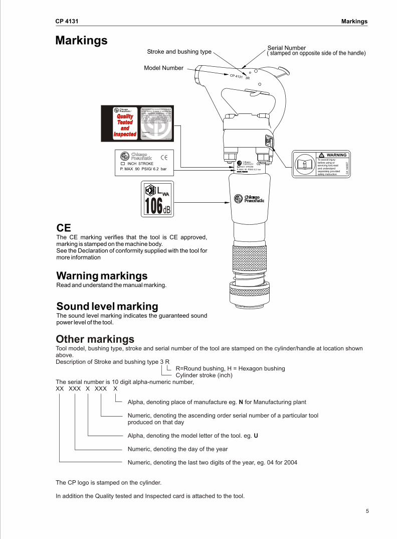
CEThe CE marking verifies that the tool is CE approved, marking is stamped on the machine body.See the Declaration of conformity supplied with the tool for more information
Warning markingsRead and understand the manual marking.
Sound level markingThe sound level marking indicates the guaranteed sound power level of the tool.
Markings
Other markingsTool model, bushing type, stroke and serial number of the tool are stamped on the cylinder/handle at location shown above.Description of Stroke and bushing type 3 R
R=Round bushing, H = Hexagon bushing Cylinder stroke (inch)
The serial number is 10 digit alpha-numeric number, XX XXX X XXX X
Alpha, denoting place of manufacture eg. N for Manufacturing plant Numeric, denoting the ascending order serial number of a particular tool
produced on that day
Alpha, denoting the model letter of the tool. eg. U
Numeric, denoting the day of the year
Numeric, denoting the last two digits of the year, eg. 04 for 2004
The CP logo is stamped on the cylinder.
In addition the Quality tested and Inspected card is attached to the tool.
WARNINGTo avovid injurybefore using orservicing tool,readand understandseparately providedsafety instruction C
A 1
44
00
7
W
To
fbe
serand s pe
safe
3CP 41 1 3R
Stroke and bushing type
Model Number
Serial Number ( stamped on opposite side of the handle)
INCH STROKE
P. MAX 90 PSIG/ 6.2 bar INCH STROKE
P. MAX 90 PSIG/ 6.2 barNACKA SWEDENNACKA SWEDEN
106dBdBdB
LLLWAWAWA
Design and function
6
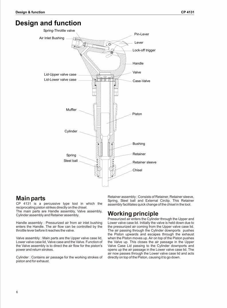
Main partsCP 4131 is a percussive type tool in which the reciprocating piston strikes directly on the chisel.The main parts are Handle assembly, Valve assembly, Cylinder assembly and Retainer assembly.
Handle assembly : Pressurized air from air inlet bushing enters the Handle. The air flow can be controlled by the throttle lever before it reaches the valve.
Valve assembly : Main parts are the Upper valve case lid, Lower valve case lid, Valve case and the Valve. Function of the Valve assembly is to direct the air flow for the piston's power and return strokes.
Cylinder : Contains air passage for the working strokes of piston and for exhaust.
Retainer assembly : Consists of Retainer, Retainer sleeve, Spring, Steel ball and External Circlip. This Retainer assembly facilitates quick change of the chisel in the tool.
Working principle Pressurized air enters the Cylinder through the Upper and Lower valve case lid. Initially the valve is held down due to the pressurized air coming from the Upper valve case lid. The air passing through the Cylinder downports pushes the Piston upwards and escapes through the exhaust when the Piston moves up. Air on top of the Piston pushes the Valve up. This closes the air passage in the Upper Valve Case Lid passing to the Cylinder downports and opens up the air passage in the Lower valve case lid. The air now passes through the Lower valve case lid and acts directly on top of the Piston, causing it to go down.
Design & function CP 4131
Steel ball
Cylinder
MufflerPiston
Bushing
Chisel
Retainer
Lid-Lower valve case
Lid-Upper valve case
Spring-Throttle valve
Air Inlet Bushing
Lock-off trigger
Case-Valve
Pin-Lever
Handle
Lever
Valve
Spring
Retainer sleeve
CP 4131
7
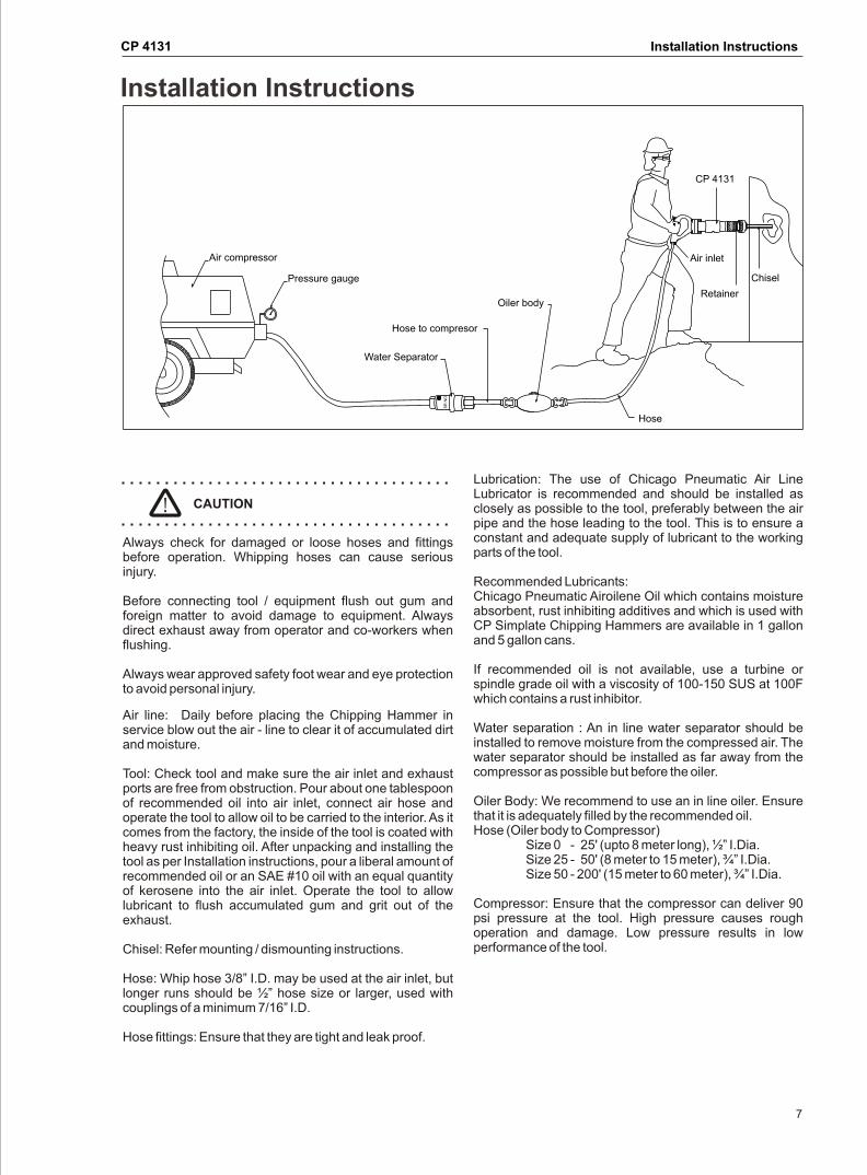
Air line: Daily before placing the Chipping Hammer in service blow out the air - line to clear it of accumulated dirt and moisture.
Tool: Check tool and make sure the air inlet and exhaust ports are free from obstruction. Pour about one tablespoon of recommended oil into air inlet, connect air hose and operate the tool to allow oil to be carried to the interior. As it comes from the factory, the inside of the tool is coated with heavy rust inhibiting oil. After unpacking and installing the tool as per Installation instructions, pour a liberal amount of recommended oil or an SAE #10 oil with an equal quantity of kerosene into the air inlet. Operate the tool to allow lubricant to flush accumulated gum and grit out of the exhaust.
Chisel: Refer mounting / dismounting instructions.
Hose: Whip hose 3/8” I.D. may be used at the air inlet, but longer runs should be ½” hose size or larger, used with couplings of a minimum 7/16” I.D.
Hose fittings: Ensure that they are tight and leak proof.
Lubrication: The use of Chicago Pneumatic Air Line Lubricator is recommended and should be installed as closely as possible to the tool, preferably between the air pipe and the hose leading to the tool. This is to ensure a constant and adequate supply of lubricant to the working parts of the tool.
Recommended Lubricants:Chicago Pneumatic Airoilene Oil which contains moisture absorbent, rust inhibiting additives and which is used with CP Simplate Chipping Hammers are available in 1 gallon and 5 gallon cans.
If recommended oil is not available, use a turbine or spindle grade oil with a viscosity of 100-150 SUS at 100F which contains a rust inhibitor.
Water separation : An in line water separator should be installed to remove moisture from the compressed air. The water separator should be installed as far away from the compressor as possible but before the oiler.
Oiler Body: We recommend to use an in line oiler. Ensure that it is adequately filled by the recommended oil.Hose (Oiler body to Compressor)
Size 0 - 25' (upto 8 meter long), ½” I.Dia.Size 25 - 50' (8 meter to 15 meter), ¾” I.Dia.Size 50 - 200' (15 meter to 60 meter), ¾” I.Dia.
Compressor: Ensure that the compressor can deliver 90 psi pressure at the tool. High pressure causes rough operation and damage. Low pressure results in low performance of the tool.
Installation Instructions
Installation Instructions
CP 4131
Air compressor
Pressure gauge
Hose to compresor
Oiler body
Hose
Chisel
Retainer
Air inlet
Water Separator
SR
NO
Always check for damaged or loose hoses and fittings before operation. Whipping hoses can cause serious injury.
Before connecting tool / equipment flush out gum and foreign matter to avoid damage to equipment. Always direct exhaust away from operator and co-workers when flushing.
Always wear approved safety foot wear and eye protection to avoid personal injury.
CAUTION
CP 4131
8
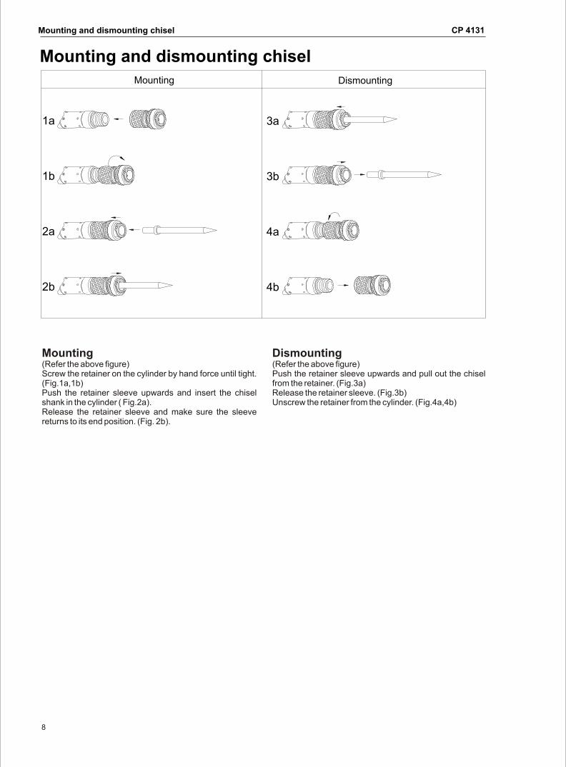
Mounting (Refer the above figure)Screw the retainer on the cylinder by hand force until tight. (Fig.1a,1b)Push the retainer sleeve upwards and insert the chisel shank in the cylinder ( Fig.2a).Release the retainer sleeve and make sure the sleeve returns to its end position. (Fig. 2b).
Dismounting (Refer the above figure)Push the retainer sleeve upwards and pull out the chisel from the retainer. (Fig.3a)Release the retainer sleeve. (Fig.3b)Unscrew the retainer from the cylinder. (Fig.4a,4b)
Mounting and dismounting chisel
Mounting and dismounting chisel
DismountingMounting
2b
2a
1b 3b
4a
4b
1a 3a
CP 4131
9
Operating
Operating
Start and Stop Instructions
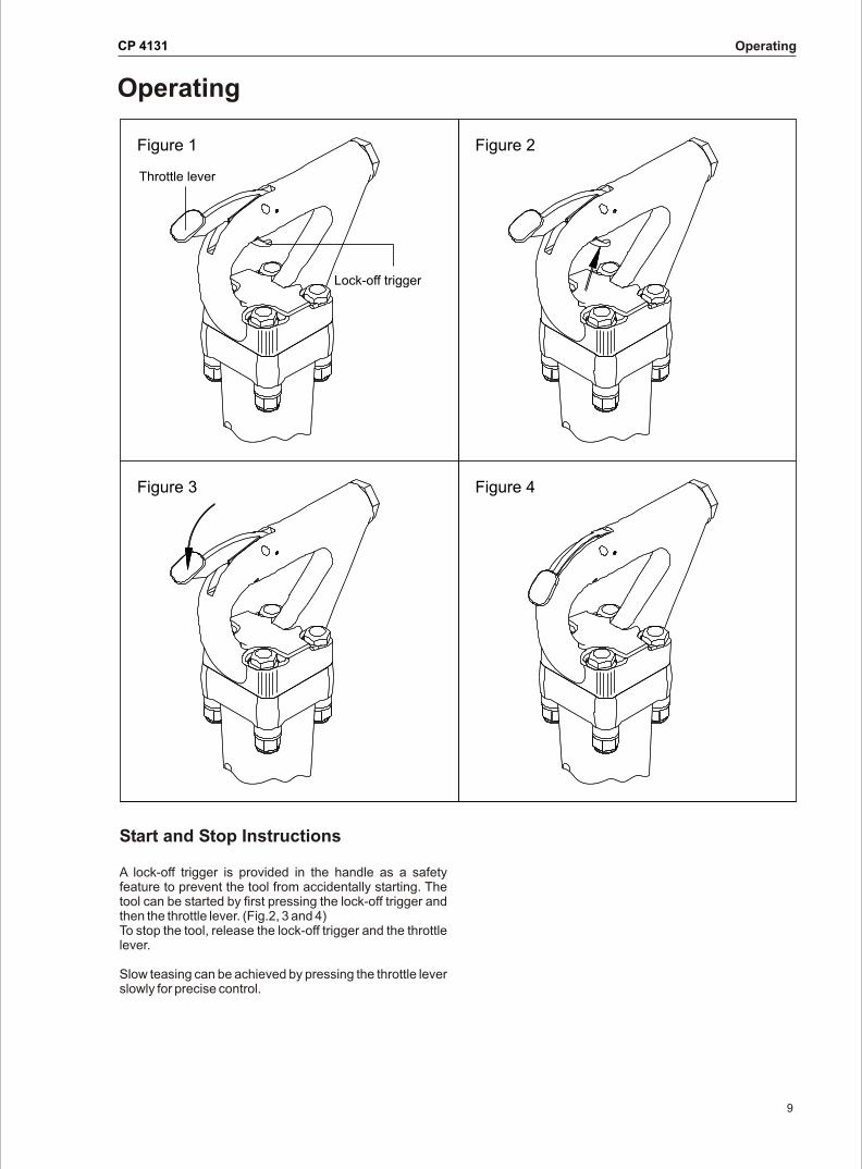
A lock-off trigger is provided in the handle as a safety feature to prevent the tool from accidentally starting. The tool can be started by first pressing the lock-off trigger and then the throttle lever. (Fig.2, 3 and 4)To stop the tool, release the lock-off trigger and the throttle lever.
Slow teasing can be achieved by pressing the throttle lever slowly for precise control.
Figure 1 Figure 2
Figure 3 Figure 4
Throttle lever
Lock-off trigger
CP 4131
10
Lack of lubrication is the chief cause of wear and consequent loss of power. Watch for oil on Chisel shank and air exhaust ports. Excess oil leads to carbon deposits on piston and cylinder causing wear.
A tool in constant use should be dismantled, cleaned and inspected at least weekly. Worn parts should be replaced to maintain operating efficiency and avoid high upkeep costs.
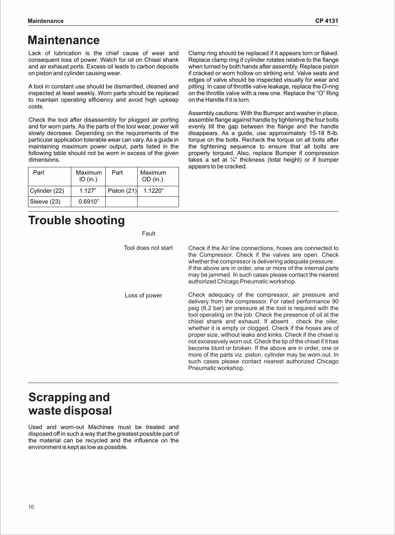
Check the tool after disassembly for plugged air porting and for worn parts. As the parts of the tool wear, power will slowly decrease. Depending on the requirements of the particular application tolerable wear can vary. As a guide in maintaining maximum power output, parts listed in the following table should not be worn in excess of the given dimensions.
Clamp ring should be replaced if it appears torn or flaked. Replace clamp ring if cylinder rotates relative to the flange when turned by both hands after assembly. Replace piston if cracked or worn hollow on striking end. Valve seats and edges of valve should be inspected visually for wear and pitting. In case of throttle valve leakage, replace the O-ring on the throttle valve with a new one. Replace the “O” Ring on the Handle if it is torn.
Assembly cautions: With the Bumper and washer in place, assemble flange against handle by tightening the four bolts evenly till the gap between the flange and the handle disappears. As a guide, use approximately 15-18 ft-lb. torque on the bolts. Recheck the torque on all bolts after the tightening sequence to ensure that all bolts are properly torqued. Also, replace Bumper if compression takes a set at ¼” thickness (total height) or if bumper appears to be cracked.
Fault
Tool does not start
Loss of power
Maintenance
Trouble shooting
Maintenance
Check if the Air line connections, hoses are connected to the Compressor. Check if the valves are open. Check whether the compressor is delivering adequate pressure.If the above are in order, one or more of the internal parts may be jammed. In such cases please contact the nearest authorized Chicago Pneumatic workshop.
Check adequacy of the compressor, air pressure and delivery from the compressor. For rated performance 90 psig (6.2 bar) air pressure at the tool is required with the tool operating on the job. Check the presence of oil at the chisel shank and exhaust. If absent , check the oiler, whether it is empty or clogged. Check if the hoses are of proper size, without leaks and kinks. Check if the chisel is not excessively worn out. Check the tip of the chisel if it has become blunt or broken. If the above are in order, one or more of the parts viz. piston, cylinder may be worn out. In such cases please contact nearest authorized Chicago Pneumatic workshop.
Scrapping and waste disposalUsed and worn-out Machines must be treated and disposed off in such a way that the greatest possible part of the material can be recycled and the influence on the environment is kept as low as possible.
Part Maximum Part Maximum ID (in.) OD (in.)
Cylinder (22) 1.127” Piston (21) 1.1220”
Sleeve (23) 0.6910”
CP 4131
11
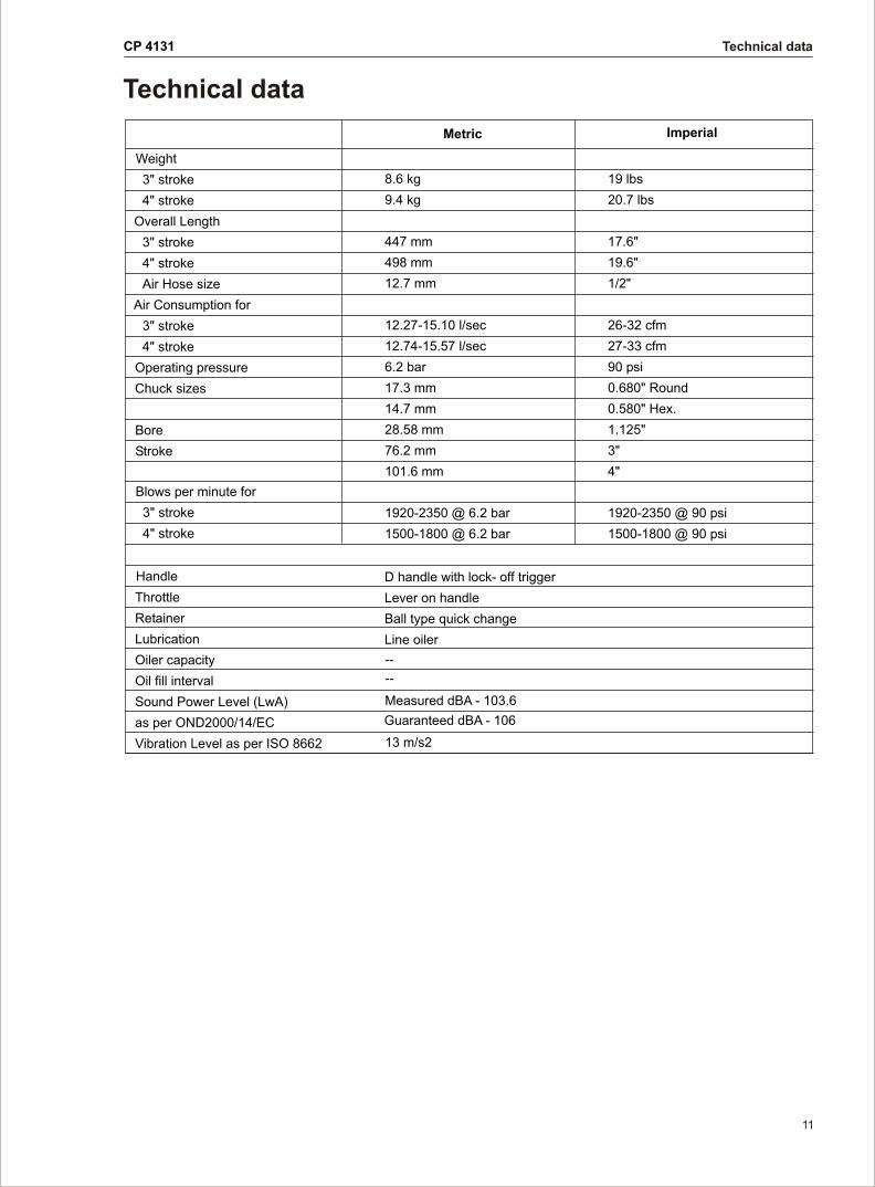
Technical data
Technical data
Metric Imperial
Weight
3" stroke
4" stroke
Overall Length
3" stroke
4" stroke
Air Hose size
Air Consumption for
3" stroke
4" stroke
Operating pressure
Chuck sizes
Bore
Stroke
Blows per minute for
3" stroke
4" stroke
Handle
Throttle
Retainer
Lubrication
Oiler capacity
Oil fill interval
Sound Power Level (LwA)
as per OND2000/14/EC
Vibration Level as per ISO 8662
8.6 kg
9.4 kg
447 mm
498 mm
12.7 mm
12.27-15.10 l/sec
12.74-15.57 l/sec
6.2 bar
17.3 mm
14.7 mm
28.58 mm
76.2 mm
101.6 mm
1920-2350 @ 6.2 bar
1500-1800 @ 6.2 bar
D handle with lock- off trigger
Lever on handle
Ball type quick change
Line oiler
--
--
Measured dBA - 103.6
Guaranteed dBA - 106
13 m/s2
19 lbs
20.7 lbs
17.6"
19.6"
1/2"
26-32 cfm
27-33 cfm
90 psi
0.680" Round
0.580" Hex.
1.125"
3"
4"
1920-2350 @ 90 psi
1500-1800 @ 90 psi

©
2004-06No. 9800 0544 01