Embed Size (px)
Citation preview

OPERATIONS MANUAL FOR AIR HEATER PROTON EC
Safety precautions
Technical parameters Installation
Construction and dimensions
www.protongroup.org
05
01
04
16
Electronically commutatedEC-motor
PROTON EC
RU
EN
ErP2015
Обращение2
1. Introduction ............................................................................................................................................................
2. Safety precautions ..............................................................................................................................................
3. General information ............................................................................................................................................
9. Connection of heat medium ............................................................................................................................
3
4
54. Dimensions .............................................................................................................................................................. 75. Construction ........................................................................................................................................................... 86. Technical characteristics .................................................................................................................................. 9
1611
18
7. Mounting consoles ..............................................................................................................................................8. Installation .............................................................................................................................................................
10. Control elements ................................................................................................................................................ 1911. Wiring control elements .................................................................................................................................. 2112. Reference information .................................................................................................................................... 27
CONTENTS
Operations manual for air heater PROTON EC:
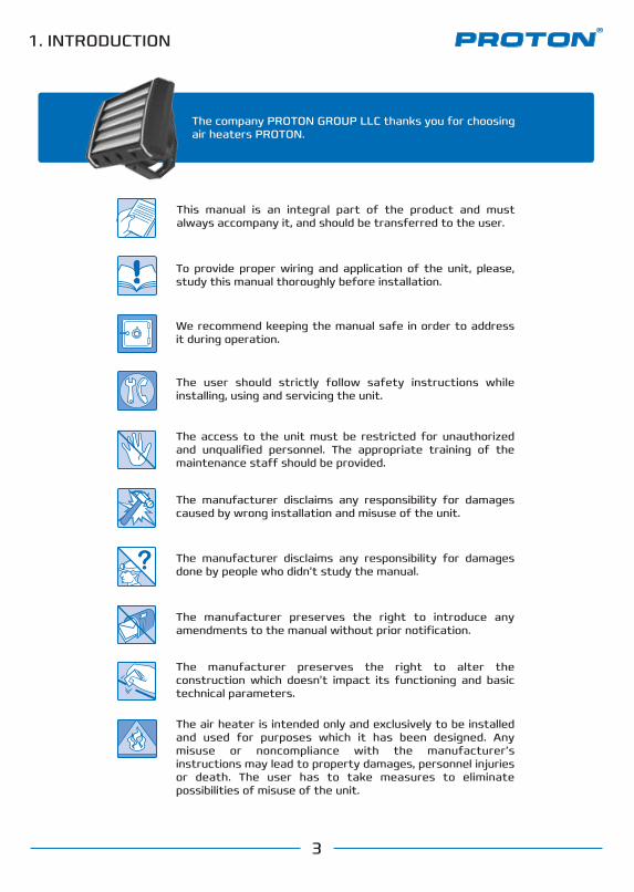
1. INTRODUCTION
The company PROTON GROUP LLC thanks you for choosing air heaters PROTON.
3
Обращение
This manual is an integral part of the product and must always accompany it, and should be transferred to the user.
The user should strictly follow safety instructions while installing, using and servicing the unit.
The manufacturer disclaims any responsibility for damages caused by wrong installation and misuse of the unit.
The manufacturer disclaims any responsibility for damages done by people who didn’t study the manual.
The manufacturer preserves the right to introduce any amendments to the manual without prior notification.
The manufacturer preserves the right to alter the construction which doesn’t impact its functioning and basic technical parameters.
The air heater is intended only and exclusively to be installed and used for purposes which it has been designed. Any misuse or noncompliance with the manufacturer’s instructions may lead to property damages, personnel injuries or death. The user has to take measures to eliminate possibilities of misuse of the unit.
The access to the unit must be restricted for unauthorized and unqualified personnel. The appropriate training of the maintenance sta� should be provided.
To provide proper wiring and application of the unit, please, study this manual thoroughly before installation.
We recommend keeping the manual safe in order to address it during operation.
3
2. SAFETY PRECAUTIONS
55
Обращение
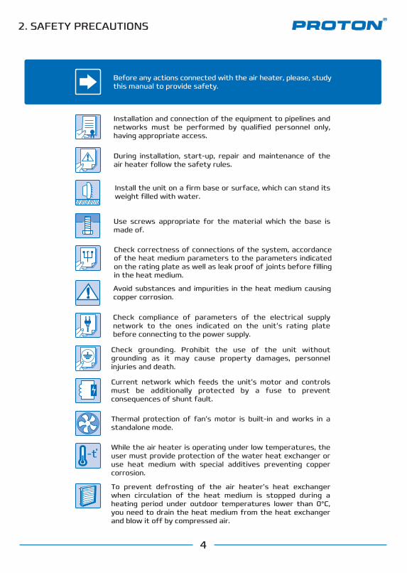
Thermal protection of fan’s motor is built-in and works in a standalone mode.
Current network which feeds the unit’s motor and controls must be additionally protected by a fuse to prevent consequences of shunt fault.
Check compliance of parameters of the electrical supply network to the ones indicated on the unit’s rating plate before connecting to the power supply.
Check grounding. Prohibit the use of the unit without grounding as it may cause property damages, personnel injuries and death.
Check correctness of connections of the system, accordance of the heat medium parameters to the parameters indicated on the rating plate as well as leak proof of joints before filling in the heat medium.
Before any actions connected with the air heater, please, study this manual to provide safety.
Installation and connection of the equipment to pipelines and networks must be performed by qualified personnel only, having appropriate access.
During installation, start-up, repair and maintenance of the air heater follow the safety rules.
Use screws appropriate for the material which the base is made of.
While the air heater is operating under low temperatures, the user must provide protection of the water heat exchanger or use heat medium with special additives preventing copper corrosion.
-t
Avoid substances and impurities in the heat medium causing copper corrosion.
Install the unit on a firm base or surface, which can stand its weight filled with water.
4
Проверьте наличие заземления. Не допускается использование щита управления без заземления, это может привести к повреждению имущества, травмам и гибели персонала.
Во время монтажа, запуска, ремонта и обслуживания щита управления соблюдайте все правила и нормы безопасности.
To prevent defrosting of the air heater’s heat exchanger when circulation of the heat medium is stopped during a heating period under outdoor temperatures lower than 0°C, you need to drain the heat medium from the heat exchanger and blow it o� by compressed air.
Принцип действия воздушно-отопительного аппарата PROTON ECO
PROTON EC 25; EC 35; EC 45; EC 55; EC 65; EC 75 PROTON EC15
Обращение
5
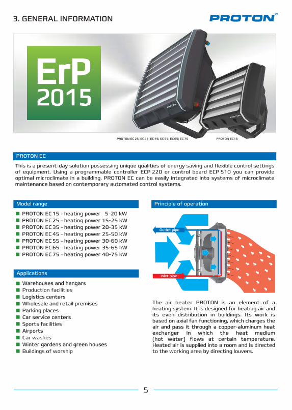
This is a present-day solution possessing unique qualities of energy saving and flexible control settings of equipment. Using a programmable controller ECP 220 or control board ECP 510 you can provide optimal microclimate in a building. PROTON EC can be easily integrated into systems of microclimate maintenance based on contemporary automated control systems.
PROTON EC
PROTON E 15 – аппарат номинальной тепловой мощностью 00.0 кВтPROTON E 25 – аппарат номинальной тепловой мощностью 00.0 кВтPROTON E 35 – аппарат номинальной тепловой мощностью 00.0 кВтPROTON E 45 – аппарат номинальной тепловой мощностью 00.0 кВтPROTON E 55 – аппарат номинальной тепловой мощностью 00.0 кВтPROTON E 65 – аппарат номинальной тепловой мощностью 00.0 кВтPROTON E 75 – аппарат номинальной тепловой мощностью 00.0 кВт
The air heater PROTON is an element of a heating system. It is designed for heating air and its even distribution in buildings. Its work is based on axial fan functioning, which charges the air and pass it through a copper-aluminum heat exchanger in which the heat medium (hot water) flows at certain temperature. Heated air is supplied into a room and is directed to the working area by directing louvers.
3. GENERAL INFORMATION
Principle of operation
Outlet pipe
Inlet pipe
Model range
PROTON EC 15 – heating power 5-20 kWPROTON EC 25 – heating power 15-25 kWPROTON EC 35 – heating power 20-35 kWPROTON EC 45 – heating power 25-50 kWPROTON EC 55 – heating power 30-60 kWPROTON EC 65 – heating power 35-65 kWPROTON EC 75 – heating power 40-75 kW
Applications
Warehouses and hangarsProduction facilitiesLogistics centersWholesale and retail premisesParking places Car service centersSports facilitiesAirports Car washesWinter gardens and green housesBuildings of worship
ErP2015
Принцип действия воздушно-отопительного аппарата PROTON ECO
Обращение
6
PROTON E 15 – аппарат номинальной тепловой мощностью 00.0 кВтPROTON E 25 – аппарат номинальной тепловой мощностью 00.0 кВтPROTON E 35 – аппарат номинальной тепловой мощностью 00.0 кВтPROTON E 45 – аппарат номинальной тепловой мощностью 00.0 кВтPROTON E 55 – аппарат номинальной тепловой мощностью 00.0 кВтPROTON E 65 – аппарат номинальной тепловой мощностью 00.0 кВтPROTON E 75 – аппарат номинальной тепловой мощностью 00.0 кВт
3. GENERAL INFORMATION
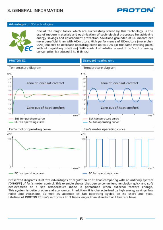
Presented diagrams illustrate advantages of regulation of EC fans comparing with an ordinary system (ON/OFF) of fan’s motor control. This example shows that due to convenient regulation quick and soft achievement of a set temperature mode is performed when external factors change.This system is quite precise and economical. In addition, it is characterized by high energy savings, low noise and vibrations as well as absence of fan operating cycles on its start and stop.Lifetime of PROTON EC fan’s motor is 2 to 3 times longer than standard unit heaters have.
One of the major tasks, which are successfully solved by this technology, is the use of modern materials and optimization of technological processes for achieving energy-savings and environment protection. Solutions grounded at EC-motors are more beneficial than with AC-motors. High performance of EC-motors (more than 90%) enables to decrease operating costs up to 30% (in the same working point, without regulating rotations). With control of rotation speed of fan’s rotor energy consumption is reduced 2 to 8 times!
Advantages of EC-technologies
PROTON EC Standard heating unit
EC fan operating curve
v (%)
100
0
AC fan operating curve
v (%)
100
0
Set temperature curveEC fan operating curve
Zone out of heat comfort
t (°C)
Time10°
12°
14°
16°
18°
20°
22°
23°
24°
Zone of low heat comfort
Set temperature curveAC fan operating curve
t (°C)
Time
Time Time
10°
12°
14°
16°
18°
20°
22°
23°
24°
Temperature diagram Temperature diagram
Fan’s motor operating curve Fan’s motor operating curve
Zone out of heat comfort
Zone of low heat comfort
4. DIMENSIONS
Обращение
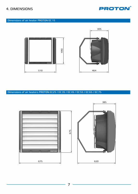
Dimensions of air heater PROTON EС 15
Dimensions of air heaters PROTON EС25 / EС 35 / EС 45 / EС 55 / EС 65 / EС 75
305
44
0
4645106
75
675
385
7
620
5. CONSTRUCTION
345688
10121416
Обращение
Casing
Fan
Heat exchanger
Directing louvers
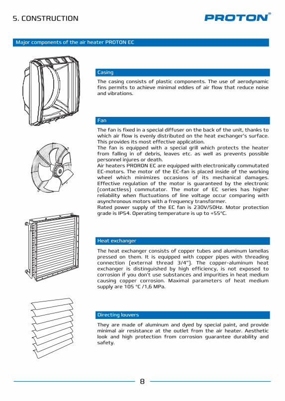
The heat exchanger consists of copper tubes and aluminum lamellas pressed on them. It is equipped with copper pipes with threading connection (external thread 3/4”). The copper-aluminum heat exchanger is distinguished by high e�ciency, is not exposed to corrosion if you don’t use substances and impurities in heat medium causing copper corrosion. Maximal parameters of heat medium supply are 105 °C /1,6 MPa.
They are made of aluminum and dyed by special paint, and provide minimal air resistance at the outlet from the air heater. Aesthetic look and high protection from corrosion guarantee durability and safety.
The fan is fixed in a special di�user on the back of the unit, thanks to which air flow is evenly distributed on the heat exchanger’s surface. This provides its most e�ective application.The fan is equipped with a special grill which protects the heater from falling in of debris, leaves etc. as well as prevents possible personnel injures or death. Air heaters PRORON EC are equipped with electronically commutated EC-motors. The motor of the EC-fan is placed inside of the working wheel which minimizes occasions of its mechanical damages. E�ective regulation of the motor is guaranteed by the electronic (contactless) commutator. The motor of EC series has higher reliability when fluctuations of line voltage occur comparing with asynchronous motors with a frequency transformer. Rated power supply of the EC fan is 230V/50Hz. Motor protection grade is IP54. Operating temperature is up to +55°C.
The casing consists of plastic components. The use of aerodynamic fins permits to achieve minimal eddies of air flow that reduce noise and vibrations.
8
Major components of the air heater PROTON EC
9
EС 15
EС 15
Parameters according to the heat medium EС 25
Parameters according to the heat medium EС 35
EС 25 EС 35 EС 45 EС 55 EС 65 EС 75
1600 1700
37.0
13
1.04
10.2
95
51
0.73
2
105
1.6
3/4
44
230/50
4700
20.6
25
1.30
15.7
220
51
1.45
1
105
1.6
3/4
54
5600
17.3
27
1.30
16.0
300
54
2.05
1
105
1.6
3/4
54
230/50 230/50
4200
38.9
24
2.25
17.2
220
51
1.45
2
105
1.6
3/4
54
230/50
5100
34.3
26
2.25
17.5
300
54
2.05
2
105
1.6
3/4
54
230/50
3800
53.6
23
3.18
19.0
220
51
1.45
3
105
1.6
3/4
54
230/50 230/50
4600
49.8
25
3.18
19.3
300
54
2.05
3
105
1.6
3/4
54
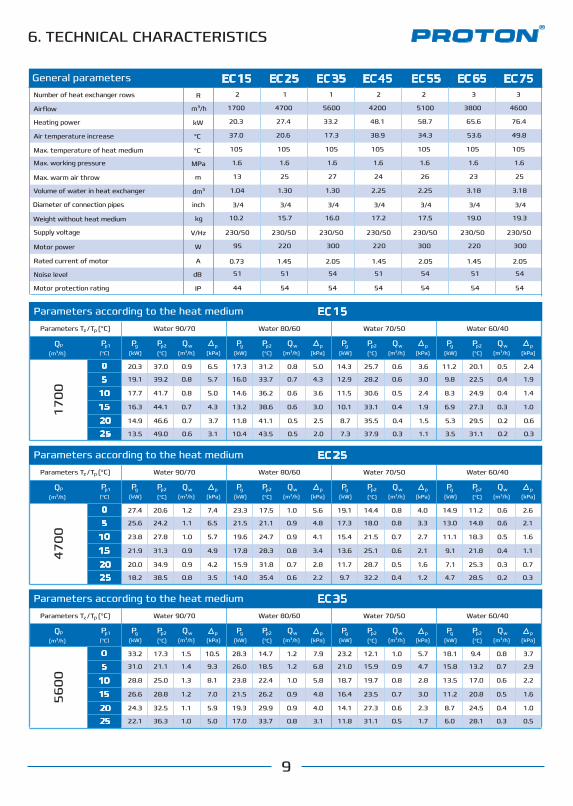
6. TECHNICAL CHARACTERISTICS
General parametersNumber of heat exchanger rows
Airflow
Heating power
Air temperature increase
Max. temperature of heat medium
Max. working pressure
Max. warm air throw
Volume of water in heat exchanger
Diameter of connection pipes
Weight without heat medium
Supply voltage
Motor power
Rated current of motor
Noise level
Motor protection rating
m³/h
kW
°С
°С
MPa
m
dm³
inch
kg
V/Hz
W
dB
А
IP
R
Parameters according to the heat medium
(m³/h) (kW) (kPa)
Pg Qw(°С)
Pp2 p(m³/h) (kW) (kPa)
Pg Qw(°С)
Pp2 p(m³/h) (kW) (kPa)
Pg Qw(°С)
Pp2 p(m³/h) (kW) (kPa)
Pg Qw(°С)
Pp2 p
Water 90/70 Water 80/60 Water 70/50 Water 60/40Parameters (°С) T /z Tp
(m³/h)
Qp
(°С)
Pp1
(m³/h) (kW) (kPa)
Pg Qw(°С)
Pp2 p(m³/h) (kW) (kPa)
Pg Qw(°С)
Pp2 p(m³/h) (kW) (kPa)
Pg Qw(°С)
Pp2 p(m³/h) (kW) (kPa)
Pg Qw(°С)
Pp2 p
Water 90/70 Water 80/60 Water 70/50 Water 60/40Parameters (°С) T /z Tp
(m³/h)
Qp
(°С)
Pp1
(m³/h) (kW) (kPa)
Pg Qw(°С)
Pp2 p(m³/h) (kW) (kPa)
Pg Qw(°С)
Pp2 p(m³/h) (kW) (kPa)
Pg Qw(°С)
Pp2 p(m³/h) (kW) (kPa)
Pg Qw(°С)
Pp2 p
Water 90/70 Water 80/60 Water 70/50 Water 60/40Parameters (°С) T /z Tp
(m³/h)
Qp
(°С)
Pp1
20.3
20.3 27.4 33.2 48.1 58.7 65.6 76.4
19.1
17.7
16.3
14.9
13.5
27.4
25.6
23.8
21.9
20.0
18.2
33.2
31.0
28.8
26.6
24.3
22.1
17.3
21.1
25.0
28.8
32.5
36.3
1.5
1.4
1.3
1.2
1.1
1.0
7.9
6.8
5.8
4.8
4.0
3.1
5.7
4.7
2.8
3.0
2.3
1.7
3.7
2.9
2.2
1.6
1.0
0.5
10.5
9.3
8.1
7.0
5.9
5.0
1.2
1.2
1.0
0.9
0.9
0.8
1.0
0.9
0.8
0.7
0.6
0.5
0.8
0.7
0.6
0.5
0.4
0.3
14.7
18.5
22.4
26.2
29.9
33.7
12.1
15.9
19.7
23.5
27.3
31.1
9.4
13.2
17.0
20.8
24.5
28.1
28.3
26.0
23.8
21.5
19.3
17.0
23.2
21.0
18.7
16.4
14.1
11.8
18.1
15.8
13.5
11.2
8.7
6.0
20.6
24.2
27.8
31.3
34.9
38.5
1.2
1.1
1.0
0.9
0.9
0.8
7.4
6.5
5.7
4.9
4.2
3.5
5.6
4.8
4.1
3.4
2.8
2.2
4.0
3.3
2.7
2.1
1.6
1.2
2.6
2.1
1.6
1.1
0.7
0.3
1.0
0.9
0.9
0.8
0.7
0.6
0.8
0.8
0.7
0.6
0.5
0.4
0.6
0.6
0.5
0.4
0.3
0.2
17.5
21.1
24.7
28.3
31.8
35.4
14.4
18.0
21.5
25.1
28.7
32.2
11.2
14.8
18.3
21.8
25.3
28.5
23.3
21.5
19.6
17.8
15.9
14.0
19.1
17.3
15.4
13.6
11.7
9.7
14.9
13.0
11.1
9.1
7.1
4.7
37.0
39.2
41.7
44.1
46.6
49.0
31.2
33.7
36.2
38.6
41.1
43.5
25.7
28.2
30.6
33.1
35.5
37.9
20.1
22.5
24.9
27.3
29.5
31.1
17.3
16.0
14.6
13.2
11.8
10.4
14.3
12.9
11.5
10.1
8.7
7.3
11.2
9.8
8.3
6.9
5.3
3.5
0.9
0.8
0.8
0.7
0.7
0.6
6.5
5.7
5.0
4.3
3.7
3.1
0.8
0.7
0.6
0.6
0.5
0.5
5.0
4.3
3.6
3.0
2.5
2.0
3.6
3.0
2.4
1.9
1.5
1.1
2.4
1.9
1.4
1.0
0.6
0.3
0.6
0.6
0.5
0.4
0.4
0.3
0.5
0.4
0.4
0.3
0.2
0.2
17
00
47
00
56
00
0
5
10
15
20
25
0
5
10
15
20
25
0
5
10
15
20
25

Parameters according to the heat medium EС 45
Parameters according to the heat medium EС 55
Parameters according to the heat medium EС 65
Parameters according to the heat medium EС 75
42
00
0
5
10
15
20
25
4.8
6. TECHNICAL CHARACTERISTICS 5
10
0
0
5
10
15
20
25
38
00
0
5
10
15
20
25
46
00
0
5
10
15
20
25
10
48.1
41.8
38.6
35.4
32.3
45.0
58.7
51.0
47.1
43.3
39.3
54.9
65.6
57.2
53.0
48.9
44.7
61.4
76.4
66.6
61.7
56.8
51.9
71.5
49.8
53.3
55.0
56.7
58.3
51.6
3.4
3.0
2.7
2.5
2.3
3.2
2.9
2.4
2.2
2.0
1.8
2.7
2.4
2.0
1.8
1.5
1.3
2.2
1.9
1.5
1.3
1.0
0.8
1.7
9.1
5.6
4.2
2.9
1.8
7.3
42.9
46.3
48.0
49.7
51.3
44.6
35.8
39.2
40.9
42.5
44.1
37.5
28.7
32.0
33.6
35.1
36.4
30.4
65.7
55.8
50.9
45.9
40.9
60.8
24.0
18.6
16.2
13.8
11.7
21.2
13.4
9.3
7.5
5.8
4.4
11.3
18.4
13.6
11.5
9.5
7.7
15.9
54.9
45.0
39.9
34.9
29.7
49.9
43.9
33.8
28.6
23.3
17.8
38.9
53.6
56.6
58.1
59.5
61.0
55.1
2.9
2.5
2.3
2.2
2.0
2.7
2.5
2.1
1.9
1.7
1.5
2.3
18.1
14.0
12.2
10.5
8.9
16.0
13.9
10.3
8.7
7.2
5.8
12.0
10.2
7.1
5.7
4.4
3.3
8.6
2.1
1.7
1.5
1.3
1.1
1.9
1.7
1.3
1.1
0.9
0.7
1.5
6.9
4.3
3.2
2.2
1.3
5.5
46.2
49.1
50.6
52.0
53.4
47.7
38.6
41.6
43.0
44.4
45.7
40.1
30.9
33.8
35.1
36.3
37.3
32.4
56.4
48.0
43.8
39.6
35.3
52.4
47.2
38.7
34.4
30.1
25.7
43.0
37.8
29.2
24.7
20.1
15.3
33.5
19.2
14.8
12.7
1.9
9.1
16.9
14.6
10.7
8.9
7.3
5.9
12.6
10.5
7.2
5.7
4.4
3.2
8.8
34.3
39.6
42.3
44.9
47.6
36.9
2.6
2.3
2.1
1.9
1.7
2.4
2.2
1.9
1.7
1.5
1.3
2.1
1.8
1.5
1.3
1.1
1.0
1.7
1.4
1.1
0.9
0.7
0.5
1.3
7.0
4.3
3.1
2.1
1.2
5.6
29.3
34.6
37.3
40.0
42.6
32.0
24.3
29.6
32.3
34.9
37.5
26.9
19.2
24.5
27.1
29.7
32.2
21.9
50.2
42.5
38.5
34.6
30.7
46.4
41.6
33.8
29.8
25.9
21.8
37.7
32.9
25.0
21.0
16.8
12.5
29.0
38.9
43.6
46.0
48.3
50.7
41.3
13.2
10.2
8.8
7.5
6.3
11.7
10.1
7.4
6.2
5.1
4.1
8.7
2.1
1.8
1.7
1.6
1.4
2.0
1.8
1.5
1.4
1.3
1.1
1.7
7.3
5.0
4.0
3.1
2.3
6.1
4.9
3.0
2.2
1.5
0.8
3.9
1.5
1.2
1.1
0.9
0.8
1.4
1.2
0.9
0.8
0.6
0.4
1.0
33.3
38.0
40.4
42.7
45.0
35.6
27.6
32.3
34.7
37.0
39.3
30.0
21.8
26.5
28.8
31.0
33.1
24.2
41.1
34.8
31.6
28.4
25.1
38.0
34.1
27.7
24.5
21.2
17.9
30.9
27.0
20.5
17.1
13.8
10.1
23.8
Pg
Qw
Pp2
p
Pp1
Data on operating characteristics of air heater PROTON, when using heat medium with di�ering temperatures, is to be provided on demand.There is danger of heat exchanger defrosting (breakage) if room temperature falls lower than 0 °C.As maximal pressure of the heat medium is 1,6 MPa, the water circuit system must have protection from pressure rise higher than accepted value.
– air temperature at the inlet of the unit
– air temperature at the outlet of the unit
– heat power of the unit
– air consumptionPp Qp
Pz – water temperature at the inlet of the unit
– water temperature at the outlet of the unit
– water pressure drop in heat exchanger– water consumption
(m³/h) (kW) (kPa)
Pg Qw(°С)
Pp2 p(m³/h) (kW) (kPa)
Pg Qw(°С)
Pp2 p(m³/h) (kW) (kPa)
Pg Qw(°С)
Pp2 p(m³/h) (kW) (kPa)
Pg Qw(°С)
Pp2 p
Water 90/70 Water 80/60 Water 70/50 Water 60/40Parameters (°С) T /z Tp
(m³/h)
Qp
(°С)
Pp1
(m³/h) (kW) (kPa)
Pg Qw(°С)
Pp2 p(m³/h) (kW) (kPa)
Pg Qw(°С)
Pp2 p(m³/h) (kW) (kPa)
Pg Qw(°С)
Pp2 p(m³/h) (kW) (kPa)
Pg Qw(°С)
Pp2 p
Water 90/70 Water 80/60 Water 70/50 Water 60/40Parameters (°С) T /z Tp
(m³/h)
Qp
(°С)
Pp1
(m³/h) (kW) (kPa)
Pg Qw(°С)
Pp2 p(m³/h) (kW) (kPa)
Pg Qw(°С)
Pp2 p(m³/h) (kW) (kPa)
Pg Qw(°С)
Pp2 p(m³/h) (kW) (kPa)
Pg Qw(°С)
Pp2 p
Water 90/70 Water 80/60 Water 70/50 Water 60/40Parameters (°С) T /z Tp
(m³/h)
Qp
(°С)
Pp1
(m³/h) (kW) (kPa)
Pg Qw(°С)
Pp2 p(m³/h) (kW) (kPa)
Pg Qw(°С)
Pp2 p(m³/h) (kW) (kPa)
Pg Qw(°С)
Pp2 p(m³/h) (kW) (kPa)
Pg Qw(°С)
Pp2 p
Water 90/70 Water 80/60 Water 70/50 Water 60/40Parameters (°С) T /z Tp
(m³/h)
Qp
(°С)
Pp1
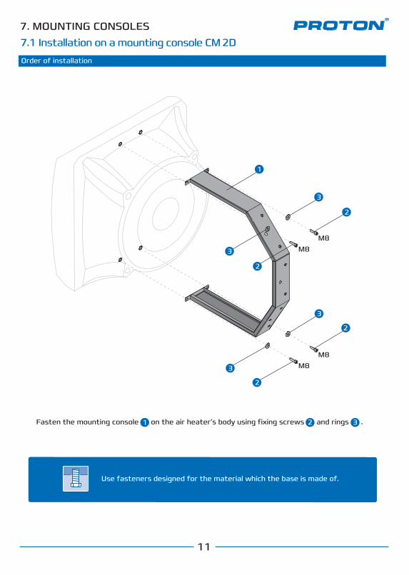
Order of installation
Fasten the mounting console on the air heater’s body using fixing screws and rings .
М8М8
М8М8
2
3
2
3
2
3
2
3
1
1 2 3
Вентилятор
Use fasteners designed for the material which the base is made of.
.
7. MOUNTING CONSOLES
11
7.1 Installation on a mounting console CM 2D

Обращение
Расположен в специально сформированном диффузоре в задней части аппарата, благодаря чему поток воздуха равномерно распределяется по всей поверхности теплообменника, обеспечивая наиболее эффективное его использование.Вентилятор оснащен специальной мелкой заборной решеткой, которая защищает аппарат от попадания в него сторонних предметов и предотвращает возможность травмирования персонала.Аппараты PROTON EC комплектуются электронно-коммутируемыми ЕС - вентиляторами. У EC-вентиляторов двигатель располагается внутри рабочего колеса, что сводит к минимуму возможность его механических повреждений. Эффективную регулировку двигателя обеспечивает электронный (бесконтактный) коммутатор. Двигатель EC имеет более высокую надежность при колебаниях напряжения сети, по сравнению с асинхронным двигателем с частотным преобразователем, являясь при этом безколлекторным двигателем, что увеличивает ресурс его работы. Номинальное питание вентилятора EC осуществляется от источника 230В/50 Гц. Уровень защиты двигателя IP54 (EN60529), класс изоляции B. Температура эксплуатации до +60 °С.
9120 510
12
30
45
62
0
12
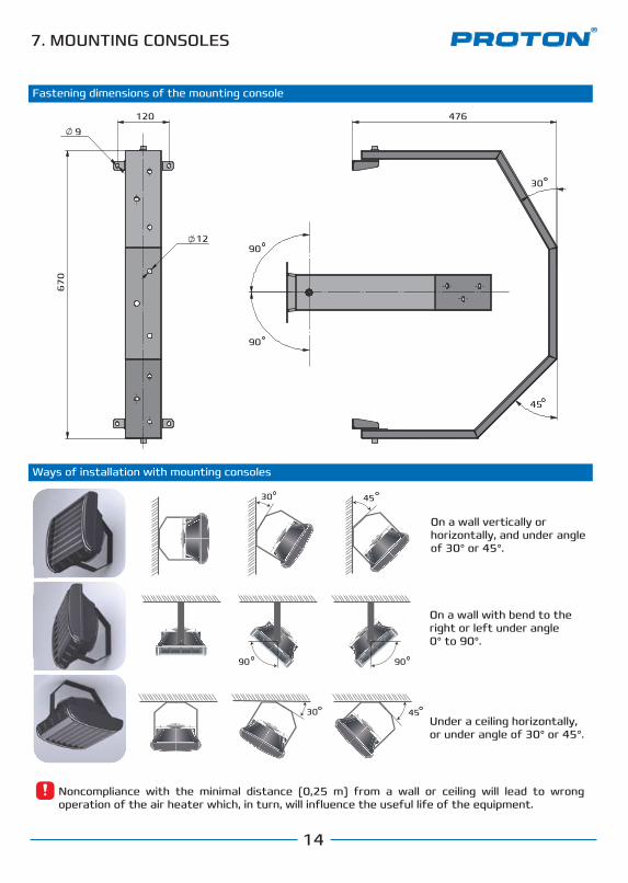
Fastening dimensions of the mounting console
Ways of installation with mounting consoles
Noncompliance with the minimal distance (0,25 m) from a wall or ceiling will lead to wrong operation of the air heater which, in turn, will influence the useful life of the equipment.
30 45
30 45
On a wall vertically or horizontally, and under angle of 30° or 45°.
Under a ceiling horizontally, or under angle of 30° or 45°.
7. MOUNTING CONSOLES
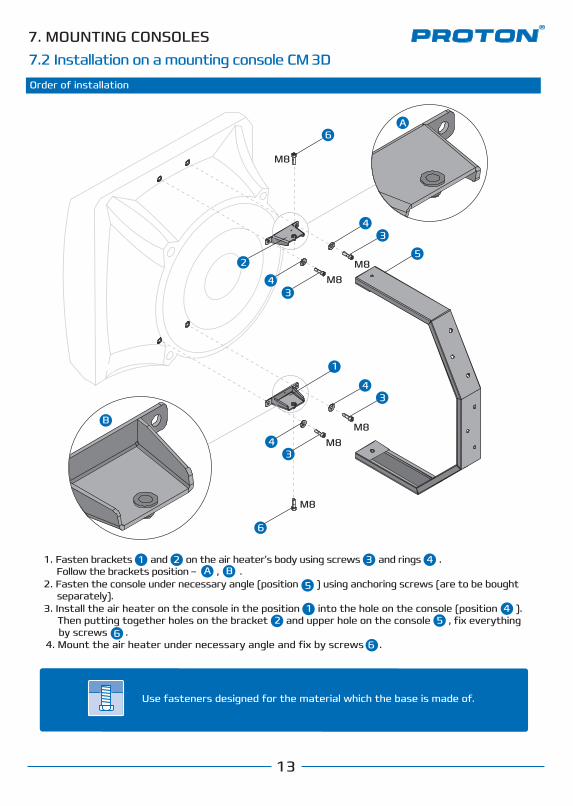
7. MOUNTING CONSOLES 7.2 Installation on a mounting console CM 3D
13
Order of installation
1. Fasten brackets and on the air heater’s body using screws and rings . Follow the brackets position – , .2. Fasten the console under necessary angle (position ) using anchoring screws (are to be bought separately).3. Install the air heater on the console in the position into the hole on the console (position ). Then putting together holes on the bracket and upper hole on the console , fix everything by screws .4. Mount the air heater under necessary angle and fix by screws .
5
34
34
34
1
1 2 3 4
42
1
5
56
6
A B
6
B
А6
М8
М8
М8М8
М8М8
4
2
3
Use fasteners designed for the material which the base is made of.
.
Обращение
7. MOUNTING CONSOLES
14
Fastening dimensions of the mounting console
Ways of installation with mounting consoles
67
0
30
90
9012
9
120 476
45
30 45
9090
30 45
On a wall with bend to the right or left under angle 0° to 90°.
Noncompliance with the minimal distance (0,25 m) from a wall or ceiling will lead to wrong operation of the air heater which, in turn, will influence the useful life of the equipment.
On a wall vertically or horizontally, and under angle of 30° or 45°.
Under a ceiling horizontally, or under angle of 30° or 45°.
Обращение
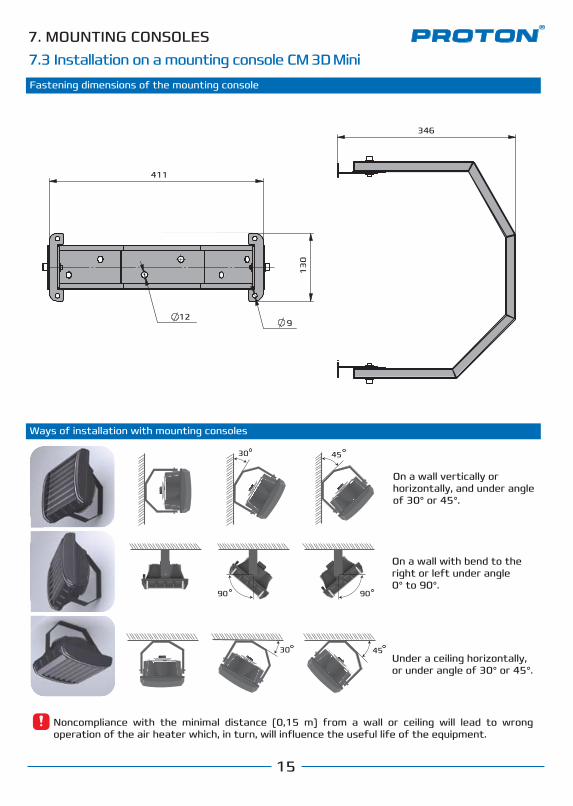
7. MOUNTING CONSOLES7.3 Installation on a mounting console CM 3D Mini
15
Fastening dimensions of the mounting console
Ways of installation with mounting consoles
30 45
9090
30 45
411
346
13
0
129
On a wall with bend to the right or left under angle 0° to 90°.
Noncompliance with the minimal distance (0,15 m) from a wall or ceiling will lead to wrong operation of the air heater which, in turn, will influence the useful life of the equipment.
On a wall vertically or horizontally, and under angle of 30° or 45°.
Under a ceiling horizontally, or under angle of 30° or 45°.
Обращение
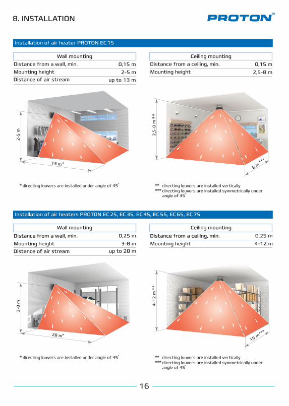
8. INSTALLATION
Installation of air heater PROTON EC 15
Installation of air heaters PROTON EC 25, EC 35, EC 45, EC 55, EC 65, EC 75
Wall mountingDistance from a wall, min. Mounting heightDistance of air stream
0,15 m2-5 m
up to 13 m
Ceiling mountingDistance from a ceiling, min. Mounting height
Distance from a wall, min. Mounting heightDistance of air stream
Distance from a ceiling, min. Mounting height
0,15 m2,5-8 m
*directing louvers are installed under angle of 45 ** directing louvers are installed vertically*** directing louvers are installed symmetrically under
angle of 45
*directing louvers are installed under angle of 45 ** directing louvers are installed vertically*** directing louvers are installed symmetrically under
angle of 45
13 m
2-5
m
*
2,5
-8 m
**
8 m***
0,25 m3-8 m
up to 28 m
0,25 m4-12 m
28 m
3-8
m
*
4-1
2 m
**
15 m***
Wall mounting Ceiling mounting
16

Обращение
8. INSTALLATION
Монтаж аппарата PROTON E 15
17
Recommended distances from walls and ceiling Manifold of a heat exchanger
Монтаж аппарата PROTON E 15Installation of a few units Recommendations of placing units
min 0,5 m
min 0,5 m
min 0,15 mmin 0,25 m
min 0,15 mmin 0,25 m
Noncompliance with the minimal distance (0,25 m (0,15 m for air heaters EC 15)) from a wall or ceiling will lead to wrong operation of the air heater which, in turn, will influence the useful life of the equipment.
When connecting the heat medium pay your attention that manifolds of the air heater must be fixed. For this use two keys: one – for fixing heat exchanger manifolds, the second – for connecting it to the system.
Examples of placing the equipment which provide even distribution of heat in a building are presented on the illustrations.
min 0,5 m
When mounting a few air heaters PROTON it is recommended to stick to the following distances between units: installation in one line – 5-9 m, installation opposite to each other – 27-35 m, installation one by one – 12-15 m.These distances are just recommendations. The installer should also take into account dimensions and shape of a building, its encumbering, and recommendations of specialists on a project.
5-9
m
12-15 m
27-35 m
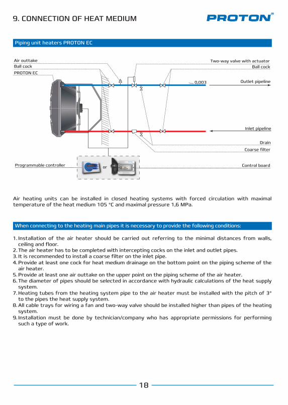
9. CONNECTION OF HEAT MEDIUM
Inlet pipeline
Coarse filter
Drain
Programmable controller
Ball cock Ball cockAir outtake Two-way valve with actuator
PROTON EC
Outlet pipeline0,003
Piping unit heaters PROTON ЕC
When connecting to the heating main pipes it is necessary to provide the following conditions:
Air heating units can be installed in closed heating systems with forced circulation with maximal temperature of the heat medium 105 °C and maximal pressure 1,6 MPa.
Installation of the air heater should be carried out referring to the minimal distances from walls, ceiling and floor.The air heater has to be completed with intercepting cocks on the inlet and outlet pipes.
1.
2.It is recommended to install a coarse filter on the inlet pipe.3.Provide at least one cock for heat medium drainage on the bottom point on the piping scheme of the air heater.
4.
Provide at least one air outtake on the upper point on the piping scheme of the air heater.5.The diameter of pipes should be selected in accordance with hydraulic calculations of the heat supply system.
6.
Heating tubes from the heating system pipe to the air heater must be installed with the pitch of 3° to the pipes the heat supply system.
7.
All cable trays for wiring a fan and two-way valve should be installed higher than pipes of the heating system.
8.
Installation must be done by technician/company who has appropriate permissions for performing such a type of work.
9.
Обращение18
Control boardor
SRV Two-way valve with actuator
19
ECP 220 Programmable сontroller
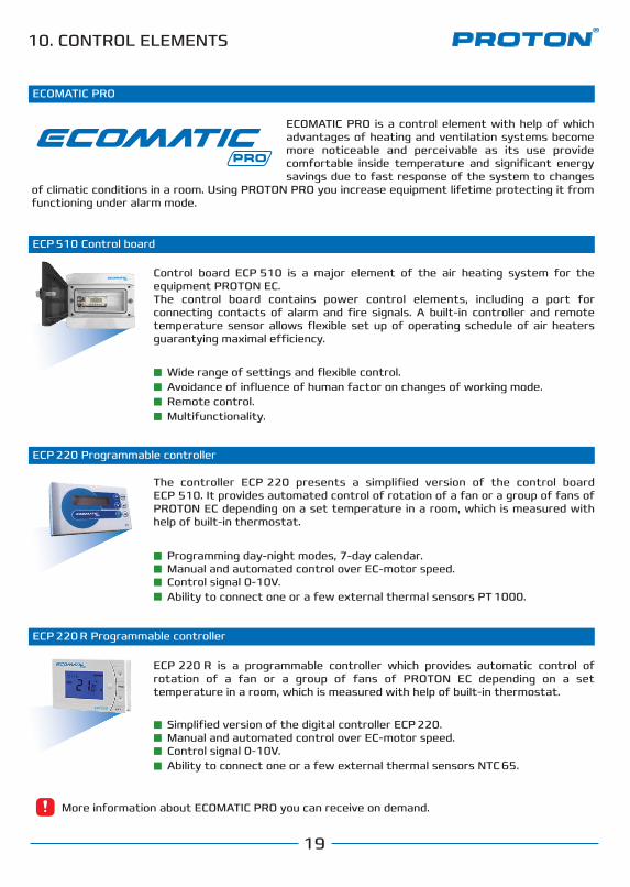
The controller ECP 220 presents a simplified version of the control board ECP 510. It provides automated control of rotation of a fan or a group of fans of PROTON EC depending on a set temperature in a room, which is measured with help of built-in thermostat.
ECP 220 R Programmable сontroller
ECP 220 R is a programmable controller which provides automatic control of rotation of a fan or a group of fans of PROTON EC depending on a set temperature in a room, which is measured with help of built-in thermostat.
ECP 510 Control board
Control board ECP 510 is a major element of the air heating system for the equipment PROTON EC. The control board contains power control elements, including a port for connecting contacts of alarm and fire signals. A built-in controller and remote temperature sensor allows flexible set up of operating schedule of air heaters guarantying maximal e�ciency.
Programming day-night modes, 7-day calendar.Manual and automated control over EC-motor speed.Control signal 0-10V.Ability to connect one or a few external thermal sensors PT 1000.
Simplified version of the digital controller ECP 220. Manual and automated control over EC-motor speed.Control signal 0-10V.Ability to connect one or a few external thermal sensors NTC 65.
ECP 220 R – контроллер цифровой, обеспечивающий автоматическое управление оборотами двигателя вентилятора/группой вентиляторов PROTON ЕС в зависимости от заданной температуры в помещении, которая измеряется за счет встроенного термостата, а так же имеет возможность подключения внешних термодатчиков.
Доступность.Оптимальный функционал.Простота настройки и эксплуатации.Возможность подключения нескольких внешних датчиков температуры.
Ручное или автоматическое управления скоростью EC-двигателя.Управляющий сигнал 0-10В.Возможность подключения одного или нескольких термодатчиков внешних NTC 65.
Wide range of settings and flexible control.Avoidance of influence of human factor on changes of working mode. Remote control.Multifunctionality.
Контроллер ECOMATIC ECP220 представляет собой упрощенный вариант щита управления ECOMATIC ECP.
10. CONTROL ELEMENTS
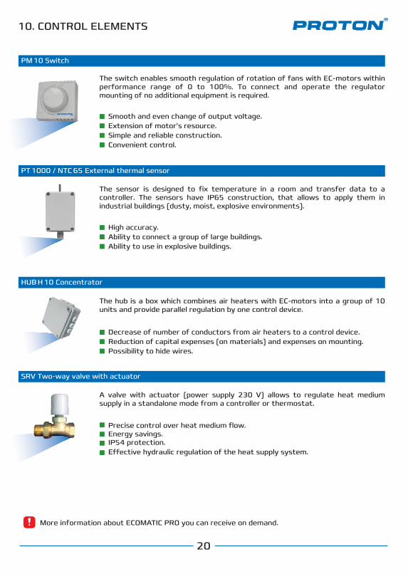
More information about ECOMATIC PRO you can receive on demand.
ECOMATIC PRO
ECOMATIC PRO is a control element with help of which advantages of heating and ventilation systems become more noticeable and perceivable as its use provide comfortable inside temperature and significant energy savings due to fast response of the system to changes
of climatic conditions in a room. Using PROTON PRO you increase equipment lifetime protecting it from functioning under alarm mode.
20
The switch enables smooth regulation of rotation of fans with EC-motors within performance range of 0 to 100%. To connect and operate the regulator mounting of no additional equipment is required.
Smooth and even change of output voltage.Extension of motor’s resource.Simple and reliable construction.Convenient control.
High accuracy.Ability to connect a group of large buildings.Ability to use in explosive buildings.
Precise control over heat medium flow.Energy savings.IP54 protection.E�ective hydraulic regulation of the heat supply system.
A valve with actuator (power supply 230 V) allows to regulate heat medium supply in a standalone mode from a controller or thermostat.
PT 1000 / NTC 65 External thermal sensor
The sensor is designed to fix temperature in a room and transfer data to a controller. The sensors have IP65 construction, that allows to apply them in industrial buildings (dusty, moist, explosive environments).
SRV Two-way valve with actuator
PM 10 Switch
The hub is a box which combines air heaters with EC-motors into a group of 10 units and provide parallel regulation by one control device.
Decrease of number of conductors from air heaters to a control device.Reduction of capital expenses (on materials) and expenses on mounting.Possibility to hide wires.
HUB H 10 Concentrator
Контроллер ECOMATIC ECP220 представляет собой упрощенный вариант щита управления ECOMATIC ECP.
Концентратор HUB H 10
ECP 220 Programmable сontroller
ECP 510 Control board
10. CONTROL ELEMENTS
More information about ECOMATIC PRO you can receive on demand.
Electronically commutatedEC-motor
11. WIRING CONTROL ELEMENTS
21
3.1 Подключение однофазных трехскоростных АС-двигателей к блоку управления POWER BOX с пультом механическим RTS 10 (подключение несколькиих вентиляторов к одному каналу)
11.1
23
0 V
/50
Hz
LNPE
B4
PM 10
ECP 510
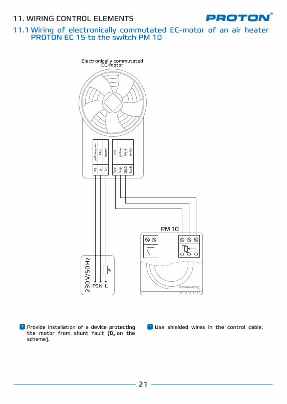
Provide installation of a device protecting the motor from shunt fault (B on the scheme).
Use shielded wires in the control cable.
Wiring of electronically commutated EC-motor of an air heater PROTON EC 15 to the switch PM 10
Tach
черн
ый
4
Термодатчик внешний PT 1000 должен быть установлен в репрезентативной точке. Следует избегать мест, непосредственно подверженных воздействию солнечного излучения, электромагнитных волн и т.п..
(NO)
(NO)
Электронно-коммутирыемыйEC-двигатель
Пульт дистанционного
управления
“Сухой контакт” противопожарной
централи
TKTKPE N L
Tach
Vcc1
Vsp
черн
ый
черн
ый
жел
то-з
елен
ый
белы
й
белы
й
сини
й
сини
й
крас
ный
жел
тый
GN
D
Электронно-коммутирыемыйEC-двигатель
TKTKPE N L
Tach
Vcc1
Vsp
черн
ый
черн
ый
жел
то-з
елен
ый
белы
й
белы
й
сини
й
сини
й
крас
ный
жел
тый
GN
D
NTC 65
4.3 Подключение щита управления ECP 510 к EC-вентиляторам
Используйте экранированные провода в кабеле управления. Термодатчик внешний NTC 65 должен быть установлен в репрезентативной точке. Следует избегать мест, непосредственно подверженных воздействию солнечного излучения, электромагнитных волн и т.п..
* В зависимости от типа мотора.
Возможно подключение к щиту нескольких аппаратов с EC-моторами*
ПДУ
+12
VD
C
GN
D B A
xx
SF
PEN 1 2 3 4 5 6 8 97L
1
1
1 2
1110 12
Tach
Vcc
Vsp
blac
k
PE N L 1
brow
n
yello
w-g
reen
blue
whi
te
red
yello
w
GN
D
4
Electronically commutatedEC-motor
TKTKPE N L
Tach
Vcc1
Vsp
blac
k
blac
k
yello
w-g
reen
whi
te
whi
te
blue
blue red
yello
w
GN
D
11. WIRING CONTROL ELEMENTS
22
3.1 Подключение однофазных трехскоростных АС-двигателей к блоку управления POWER BOX с пультом механическим RTS 10 (подключение несколькиих вентиляторов к одному каналу)
11.2
23
0 V
/50
Hz
LNPE
B4
PM 10
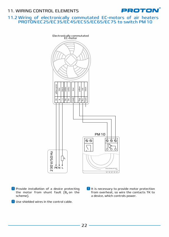
It is necessary to provide motor protection from overheat, so wire the contacts TK to a device, which controls power.
Use shielded wires in the control cable.
Wiring of electronically commutated EC-motors of air heaters PROTON EС 25/EС 35/EС 45/EС 55/EС 65/EС 75 to switch PM 10
Provide installation of a device protecting the motor from shunt fault (B on the scheme).
4
11. WIRING CONTROL ELEMENTS
23
3.1 Подключение однофазных трехскоростных АС-двигателей к блоку управления POWER BOX с пультом механическим RTS 10 (подключение несколькиих вентиляторов к одному каналу)
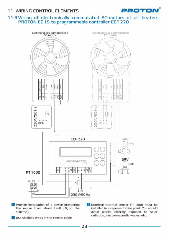
11.3
ECP 220
PT 1000
External thermal sensor PT 1000 must be installed in a representative point. You should avoid places directly exposed to solar radiation, electromagnetic waves, etc.
Wiring of electronically commutated EC-motors of air heaters PROTON EC 15 to programmable controller ECP 220
Electronically commutatedEC-motor
Electronically commutatedEC-motor
(NO)
(NO)
Pt
1
G0
AO
UT
NOL N
COM
NC
Pt
2
В A
B4
230 V/50 HzL N
SRV
SRV
Tach
Vcc
VspPE N L 1
GN
D
23
0 V
/50
Hz
LNPE
B4
23
0 V
/50
Hz
LNPE
B4
Tach
Vcc
VspPE N L 1
GN
Dbl
ack
brow
n
yello
w-g
reen
blue
whi
te
red
yello
w
blac
k
brow
n
yello
w-g
reen
blue
whi
te
red
yello
w
Use shielded wires in the control cable.
Provide installation of a device protecting the motor from shunt fault (B on the scheme).
4
11. WIRING CONTROL ELEMENTS
24
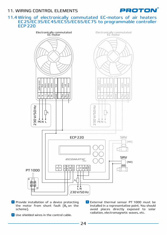
11.4
ECP 220
PT 1000
Wiring of electronically commutated EC-motors of air heaters EС 25/EС 35/EС 45/EС 55/EС 65/EС 75 to programmable controller ECP 220
TKTKPE N L
Tach
Vcc1
Vsp
GN
D
TKTKPE N L
Tach
Vcc1
Vsp
GN
D
(NO)
(NO)
Pt
1
G0
AO
UT
NOL N
COM
NC
Pt
2
В A
B4
L
L N
NPE
B4
LNPE
B4
SRV
SRV
External thermal sensor PT 1000 must be installed in a representative point. You should avoid places directly exposed to solar radiation, electromagnetic waves, etc.
Electronically commutatedEC-motor
Electronically commutatedEC-motor
230 V/50 Hz
23
0 V
/50
Hz
23
0 V
/50
Hz
Use shielded wires in the control cable.
Provide installation of a device protecting the motor from shunt fault (B on the scheme).
4
blac
k
blac
k
yello
w-g
reen
whi
te
whi
te
blue
blue red
yello
w
blac
k
blac
k
yello
w-g
reen
whi
te
whi
te
blue
blue red
yello
w
11. WIRING CONTROL ELEMENTS
25
3.1 Подключение однофазных трехскоростных АС-двигателей к блоку управления POWER BOX с пультом механическим RTS 10 (подключение несколькиих вентиляторов к одному каналу)
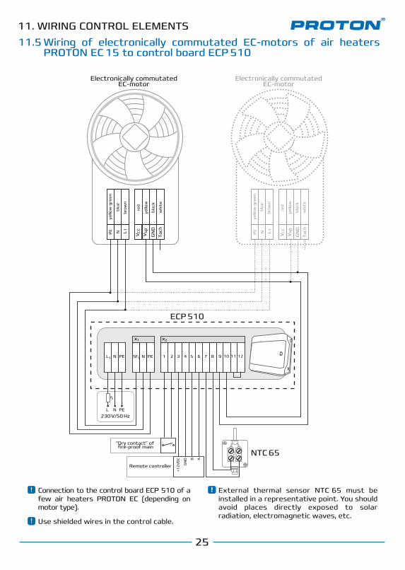
11.5
ECP 510
Connection to the control board ECP 510 of a few air heaters PROTON EC (depending on motor type).
External thermal sensor NTC 65 must be installed in a representative point. You should avoid places directly exposed to solar radiation, electromagnetic waves, etc.
Use shielded wires in the control cable.
Wiring of electronically commutated EC-motors of air heaters PROTON EC 15 to control board ECP 510
Electronically commutatedEC-motor
Electronically commutatedEC-motor
NTC 65
ПДУ
+12
VD
C
GN
D B A
xx
SF
PEN 1 2 3 4 5 6 8 97L
1
1
1 2
1110 12
Tach
Vcc
VspPE N L 1
GN
D
Tach
Vcc
VspPE N L 1
GN
D
ECP 510
NTC 65
+12
VD
C
GN
D B A
xx
PENPENL
PENL
1 2 3 4 5 6 8 97
1 2
1110 12
Tach
Vcc
VspPE N L 1
GN
D
Tach
Vcc
VspPE N L 1
GN
D
SF11
230 V/50 Hz
B4
blac
k
brow
n
yello
w-g
reen
blue
whi
te
red
yello
w
blac
k
brow
n
yello
w-g
reen
blue
whi
te
red
yello
w
Remote controller
“Dry contact” of fire-proof main
11. WIRING CONTROL ELEMENTS
26
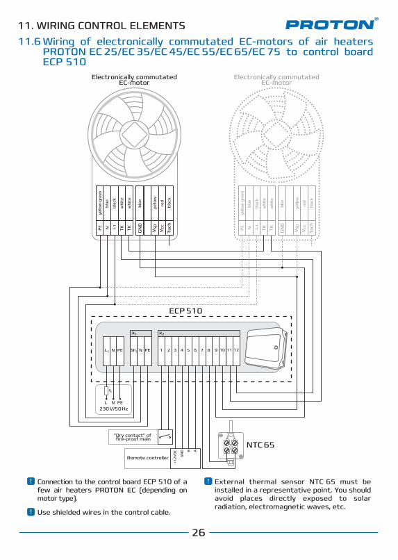
11.6
ECP 510
Wiring of electronically commutated EC-motors of air heaters PROTON EС 25/EС 35/EС 45/EС 55/EС 65/EС 75 to control board ECP 510
TKTKPE N L
Tach
Vcc1
Vsp
GN
D
TKTKPE N L
Tach
Vcc1
Vsp
GN
D
NTC 65
ПДУ
+12
VD
C
GN
D B A
xx
SF
PEN 1 2 3 4 5 6 8 97L
1
1
1 2
1110 12
Connection to the control board ECP 510 of a few air heaters PROTON EC (depending on motor type).
External thermal sensor NTC 65 must be installed in a representative point. You should avoid places directly exposed to solar radiation, electromagnetic waves, etc.
Use shielded wires in the control cable.
Electronically commutatedEC-motor
Electronically commutatedEC-motor
Remote controller
“Dry contact” of fire-proof main
ECP 510
TKTKPE N L
Tach
Vcc1
Vsp
GN
D
TKTKPE N L
Tach
Vcc1
Vsp
GN
D
NTC 65
+12
VD
C
GN
D B A
xx
PEN 1 2 3 4 5 6 8 97
1 2
1110 12PENL
PENL
SF11
230 V/50 Hz
B4
blac
k
blac
k
yello
w-g
reen
whi
te
whi
te
blue
blue red
yello
w
blac
k
blac
k
yello
w-g
reen
whi
te
whi
te
blue
blue red
yello
w
Remote controller
“Dry contact” of fire-proof main
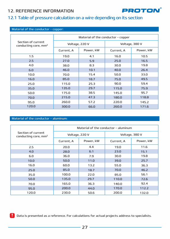
12. REFERENCE INFORMATION12.1 Table of pressure calculation on a wire depending on its section
27
Data is presented as a reference. For calculations for actual projects address to specialists.
Section of current conducting core, mm
Material of the conductor – copper
Voltage, 220 V Voltage, 380 V
Current, A Power, kW Current, A Power, kW
1.52.54.0
6.010.016.025.035.050.070.095.0
120.0
4.15.98.3
10.115.418.725.329.738.547.357.266.0
10.516.519.826.4
49.559.475.995.7
118.8
145.2171.6
11.615.119.825.7
36.346.256.172.692.4
112.2132.0
4.46.17.9
13.2
18.7
29.7
50.6
36.3
22.0
44.0
11.0
19.027.038.046.070.085.0
115.0135.0175.0215.0260.0300.0
20.028.036.050.060.085.0
100.0135.0
165.0200.0230.0
19.023.030.039.055.070.0
85.0110.0
140.0170.0200.0
16.025.030.040.050.075.090.0
115.0145.0180.0220.0260.0
33.0
Material of the conductor – aluminum:
Material of the conductor – aluminum
2.54.06.0
10.016.0
25.035.050.0
70.095.0
120.0
2
Material of the conductor – copper:
Section of current conducting core, mm Voltage, 220 V Voltage, 380 V
Current, A Power, kW Current, A Power, kW
2
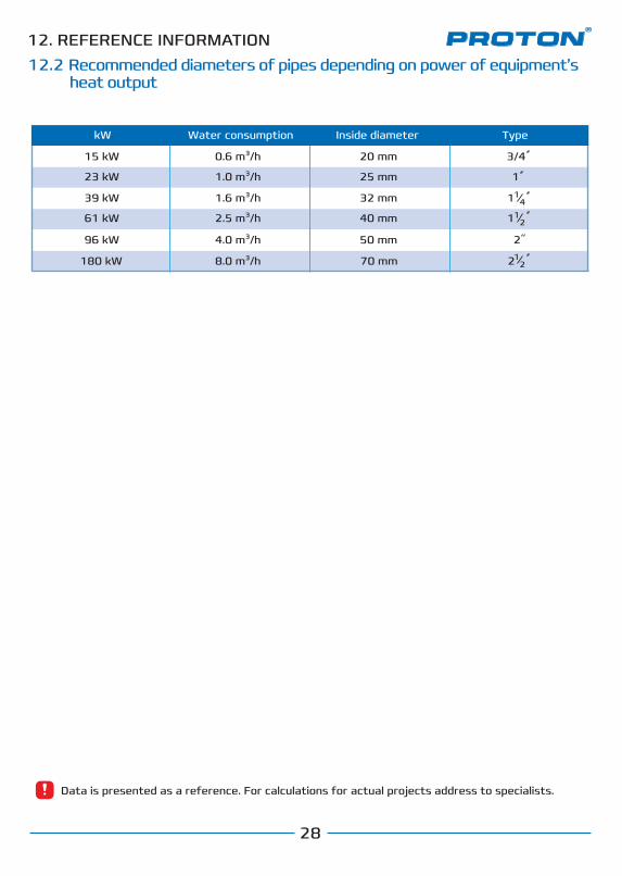
12.2 Recommended diameters of pipes depending on power of equipment’s heat output
12. СПРАВВОЧНАЯ ИНФОРМАЦИЯ12.1 Таблица расчета нагрузки на провод в зависимости от его сечения
28
12. СПРАВВОЧНАЯ ИНФОРМАЦИЯ
kW Water consumption Inside diameter Type
15 kW
23 kW
39 kW
61 kW
96 kW
180 kW
20 mm
25 mm
32 mm
40 mm
50 mm
70 mm
3/4
1
1 14
1
2
2
0.6 m³/h
1.0 m³/h
1.6 m³/h
2.5 m³/h
4.0 m³/h
8.0 m³/h
12
12
12. REFERENCE INFORMATION
Data is presented as a reference. For calculations for actual projects address to specialists.

29
Нагревательные элементы, установленные в завесах PROTON HD POWER выполнены из высоколегированной нержавеющей стали. Для лучшего съема тепла в конструкцию нагревательного элемента добавлены ребра, представляющие собой торообразную спираль шириной 10 мм с дополнительной гофровкой. Рама крепления ТЭНРов выполнена из оцинкованной стали. Клеммы коробки подключения оснащены зажимными кабель-вводами. Термодатчики защиты ТЭНРов от перегрева смонтированы в верхней и нижней части группы ТЭНРов.
Электрические ТЄНРы
Модельный ряд
PROTON E 15 – мощность нагрева 5-20 кВтPROTON E 25 – мощность нагрева 15-25 кВтPROTON E 35 – мощность нагрева 20-35 кВтPROTON E 45 – мощность нагрева 25-50 кВтPROTON E 55 – мощность нагрева 30-60 кВтPROTON E 65 – мощность нагрева 35-65 кВтPROTON E 75 – мощность нагрева 40-75 кВт
Корпус
Направляющие жалюзи
Электрические ТЄНРы
Сечение указано как минимально допустимое для медных проводов. Максимальное расстояние от щита управления ECOMATIC RDE до завес PROTON HD POWER не должно привышать 20 м.
12. СПРАВОЧНАЯ ИНФОРМАЦИЯFOR NOTES
30
Нагревательные элементы, установленные в завесах PROTON HD POWER выполнены из высоколегированной нержавеющей стали. Для лучшего съема тепла в конструкцию нагревательного элемента добавлены ребра, представляющие собой торообразную спираль шириной 10 мм с дополнительной гофровкой. Рама крепления ТЭНРов выполнена из оцинкованной стали. Клеммы коробки подключения оснащены зажимными кабель-вводами. Термодатчики защиты ТЭНРов от перегрева смонтированы в верхней и нижней части группы ТЭНРов.
Электрические ТЄНРы
Модельный ряд
PROTON E 15 – мощность нагрева 5-20 кВтPROTON E 25 – мощность нагрева 15-25 кВтPROTON E 35 – мощность нагрева 20-35 кВтPROTON E 45 – мощность нагрева 25-50 кВтPROTON E 55 – мощность нагрева 30-60 кВтPROTON E 65 – мощность нагрева 35-65 кВтPROTON E 75 – мощность нагрева 40-75 кВт
Корпус
Направляющие жалюзи
Электрические ТЄНРы
Сечение указано как минимально допустимое для медных проводов. Максимальное расстояние от щита управления ECOMATIC RDE до завес PROTON HD POWER не должно привышать 20 м.
12. СПРАВОЧНАЯ ИНФОРМАЦИЯFOR NOTES

31
Нагревательные элементы, установленные в завесах PROTON HD POWER выполнены из высоколегированной нержавеющей стали. Для лучшего съема тепла в конструкцию нагревательного элемента добавлены ребра, представляющие собой торообразную спираль шириной 10 мм с дополнительной гофровкой. Рама крепления ТЭНРов выполнена из оцинкованной стали. Клеммы коробки подключения оснащены зажимными кабель-вводами. Термодатчики защиты ТЭНРов от перегрева смонтированы в верхней и нижней части группы ТЭНРов.
Электрические ТЄНРы
Модельный ряд
PROTON E 15 – мощность нагрева 5-20 кВтPROTON E 25 – мощность нагрева 15-25 кВтPROTON E 35 – мощность нагрева 20-35 кВтPROTON E 45 – мощность нагрева 25-50 кВтPROTON E 55 – мощность нагрева 30-60 кВтPROTON E 65 – мощность нагрева 35-65 кВтPROTON E 75 – мощность нагрева 40-75 кВт
Корпус
Направляющие жалюзи
Электрические ТЄНРы
Сечение указано как минимально допустимое для медных проводов. Максимальное расстояние от щита управления ECOMATIC RDE до завес PROTON HD POWER не должно привышать 20 м.
12. СПРАВОЧНАЯ ИНФОРМАЦИЯFOR NOTES
PROTON GROUP LLC03680, Ukraine, Kyiv, 3, Nesterova str.Tel.: +380 (44) 537 0930Fax: +380 (44) 537 0903E-mail: [email protected]
www.protongroup.org
In case of any failures in operation of equipment address the authorized support centers of the Manufacturer.For information about support centers and procedure of claim submission contact Manufacturer’s service department:
Service department