Embed Size (px)
Citation preview

Oil HeatNorth Seattle Community College HVAC Program
Instructor – Mark T. Weber, M.Ed., CMHE
Oil - 1

Objectives
• After studying this chapter, you should be able to:– Describe various types of fuel oil– List and describe the characteristics
associated with fuel oil– Describe different methods for storing fuel
oil– Explain how oil tanks are sized

Objectives (cont’d.)
– Explain the importance of periodic oil tank inspection
– Describe how fuel oil and air are prepared and mixed in the oil burner unit for combustion
– List products of combustion of the fuel oil– List the components of gun-type oil burners– Describe basic service procedures for oil
burner components
Objectives (cont’d.)
– Sketch wiring diagrams of the oil burner primary control system and the fan circuit
– State tests used to determine oil burner efficiency
– Explain corrective actions that may be taken to improve burner efficiency, as indicated from the results of each test
– Describe preventive maintenance procedurs
Safety Checklist
• Do not reset any primary control too many times because unburned oil may accumulate after each reset
• Do not start a burner if heat exchanger is cracked or otherwise defective

Safety Checklist (cont'd.)
• Do not start burner with the fuel pump bypass plug in place unless the oil delivery system is configured as a two-pipe system with both a supply and return line
• When conducting flue-gas efficiency tests, avoid burns by not touching the hot flue-gas pipe

Safety Checklist (cont'd.)
• Keep your distance from the ignition arc• Observe all electrical safety precautions• Inspect oil burners and lines for leaks• When installing oil tanks, make certain
that all codes are followed• Oil tanks need to be inspected
periodically to minimize tank leakage

Introduction to Oil-Fired Forced-Warm-Air Furnaces
• Oil-fired forced-warm-air furnaces have two main systems:– A heat-producing system, consisting of the
oil burner, fuel supply components, combustion chamber, and heat exchanger
– A heat-distributing system, consisting of the blower, and other related components
• When thermostat calls for heat, ignition system is powered and oil burner motor starts

Physical Characteristics• Lowboy
– Often used if there is not much headroom– May have a cooling coil on top to provide air
conditioning
• Upflow– Vertical furnace in which the air is taken in
at the bottom, forced across the heat exchanger and out the top

Physical Characteristics (cont'd.)
• Downflow– Looks similar to an upflow furnace except
that air is drawn in from the top and forced out the bottom
• Horizontal– Usually installed in a crawlspace under a
house or in an attic– Available with right-to-left or left-to-right
airflow

Fuel Oil• Delivered to the customer in liquid form
and stored in tanks either aboveground or underground
• Oil used in residential and most commercial systems in the United States: basically diesel fuel that has been dyed red for tax purposes
• Derived from crude oil by a process of distillation called cracking

Fuel Oil (cont'd.)• There are six grades of fuel oil and a
numbering system, 1 through 6, is used to identify each grade– The lower-numbered oils are called light oils
because they weigh less per gallon than the higher-numbered oils
– The lightest of these, No. 1, is most commonly known as kerosene
– Fuel oil No. 2 is known as pentane and is the most commonly used

Fuel Oil (cont'd.)• The ASTM sets standards for acceptable
ranges for fuel oil characteristics:– Flash point
• Has to do with the maximum safe storage and handling temperature for the fuel
• Lowest temperature at which vapors in air above the fuel ignite briefly when exposed to a flame
– Ignition point• A few degrees higher than flash point• Flame keeps burning because vapors keep
rising from liquid

Fuel Oil (cont'd.)– Viscosity
• Thickness of the oil under normal temperatures• Heavier oils are thicker at the same
temperatures• Expressed in Saybolt Seconds Universal (SSU)
– Carbon residue• Amount of carbon left in a sample of oil after
boiling in an oxygen-free atmosphere• Properly burned oil has no appreciable residue

Fuel Oil (cont'd.)– Water and sediment content
• Attempt to ensure that water, sediment, and other contaminant levels are as low as possible
• Sediment can form when rust forms on internal pipe; tank surfaces and sludge can form when water condensation reacts with the fuel oil
– Pour point• Lowest temperature at which the fuel can be
stored and handled• No. 2 oil is one of the lower pour point fuels; can
be used down to 20°F

Fuel Oil (cont'd.)– Ash content
• Amount of noncombustible materials contained in the fuel oil
• Can be abrasive and wear down burner components
– Distillation quality• Describes ability of the oil to be vaporized• Lighter oil turns into vapor easier than heavier oil

Oil Storage• When possible, install tanks above ground
for environmental reasons• Follow all local codes when installing• Oil tank sizing
– Tanks are available in sizes from about 100 gallons to over 1000 gallons
• Two main issues in selecting tank size are frequency of oil deliveries and quality of oil with respect to storage time
• Tank should hold about 1/3 of the annual oil consumption

Oil Storage (cont'd.)• Underground tanks
– Tanks installed underground must be protected against corrosion
– The most popular types are the STI-P3 tanks and fiberglass tanks
– See Figure 32-7 in text

Oil Storage (cont'd.)• Aboveground tanks
– Typically fabricated from 12 gauge steel and hold between 275 and 330 gallons of oil
– Polyethylene/steel tanks: tank within tank• Galvanized steel outer tank protects the
polyethylene inner tank and provides secondary containment in the event of a leaking inner tank
• Indoor oil storage– Reduces temperature fluctuation as well as
moisture and condensation inside the tank

Oil Storage (cont'd.)• Oil tank inspection and maintenance
– Aboveground tanks should be painted periodically and inspected on a regular basis
– STI-P3 tanks should be checked to ensure protective anodes are in good working order
– Tank piping should be inspected regularly for imperfections and leaks; always check for loose or missing vent and fill caps

Oil Storage (cont'd.)– Tanks should be checked for water at least
once a year• If water is present, the source of water should be
identified and the situation corrected• Tanks are tested for water content by placing a
water-sensing paste on the oil tank stick
– Visually inspect aboveground tanks for damage to pipes, caps, oil lines, tank legs, and gauges and check for traces of oil under the tank

Fuel Oil Supply Systems• Two common piping configurations:
– One-pipe system: only one pipe runs between the oil storage tank and the oil burner
• As oil is needed, it flows from tank to burner
Fuel Oil Supply Systems (cont’d.)
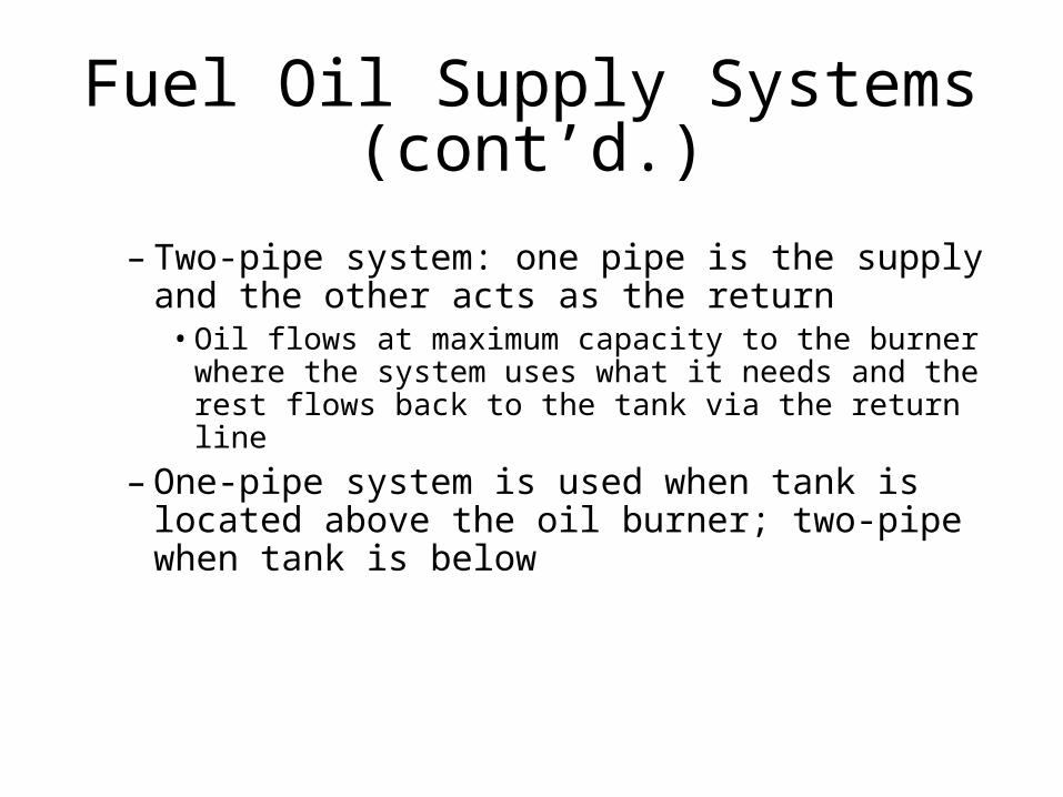
– Two-pipe system: one pipe is the supply and the other acts as the return
• Oil flows at maximum capacity to the burner where the system uses what it needs and the rest flows back to the tank via the return line
– One-pipe system is used when tank is located above the oil burner; two-pipe when tank is below

Fuel Oil Supply Systems (cont'd.)
• Key points about fuel oil lines and piping:– Oil lines should be sized at a minimum of
3/8” OD copper lines– Oil lines can be constructed of wrought iron,
steel, or brass pipe connected with malleable fittings; never use cast-iron fittings
– Never use PVC pipe for oil lines– Use only flare connections to join oil lines

Fuel Oil Supply Systems (cont'd.)
– When needed, use only a non-hardening, oil-resistant pipe joint compound
– When installing oil lines, make the runs as short as possible, use as few fittings as possible, and avoid kinking the lines
– Be sure that all oil lines are secured and protected from damage
– Ensure lines run outside are well insulated

Fuel Oil Supply Systems (cont'd.)
– Underground oil lines should be installed with secondary containment
– There should be a shutoff valve on the suction line at the oil burner
– Fill and vent pipes should pitch toward tank opening to prevent formation of oil traps
– A vent alarm should be installed in all tanks at the vent opening

Fuel Oil Supply Systems (cont'd.)
• The oil dearator allows a one-pipe system to function as a two-pipe system
• Auxiliary fuel systems get the fuel supply to the burner if it is too far above the tank
• Fuel line filters remove fine solid impurities
• Oil safety valve (OSV) stops oil flow if there is a leak in the suction line

Preparation of Fuel Oil for Combustion
• Liquid oil must be atomized (broken up into droplets)
• Oil droplets mix with air, which contains oxygen
• High-pressure gun-type oil burners feed oil through a nozzle under pressure and force air through a tube surrounding it

By-Products of Combustion• The correct ratio of fuel to air is required
for proper combustion– 1 lb of fuel oil must be mixed with about 3 lb
of oxygen for complete combustion to occur• Air is approximately 79% nitrogen and 21%
oxygen; 192 ft³ are needed to burn a single pound of fuel oil
– Most oil burners provide 50% excess air• Needs 21.6 lb or 288 ft³ of air for 1lb fuel oil
– By-products are heat, flue gases, CO2, and
water vapor

Gun-Type Oil Burner• Oil and air are forced into the burner for
mixing and ignition• Flame retention burner design improves
on conventional design• Main parts:
– Burner motor provides power for fan/pump– Burner blower forces air into the chamber– Fuel oil pumps deliver oil to the chamber– Nozzle atomizes air prior to ignition

Gun-Type Oil Burner (cont'd.)– Air tube delivers air to the chamber– Electrodes vaporize atomized oil droplets and
provide spark for ignition– Ignition transformer provides high voltage to
electrodes– Solid state igniters are found in newer oil
burners, replacing ignition transformers– Primary control unit provides means for
operating the burner and a safety function to shut down the burner if icombustion does not occur
Gun-Type Oil Burner (cont'd.)
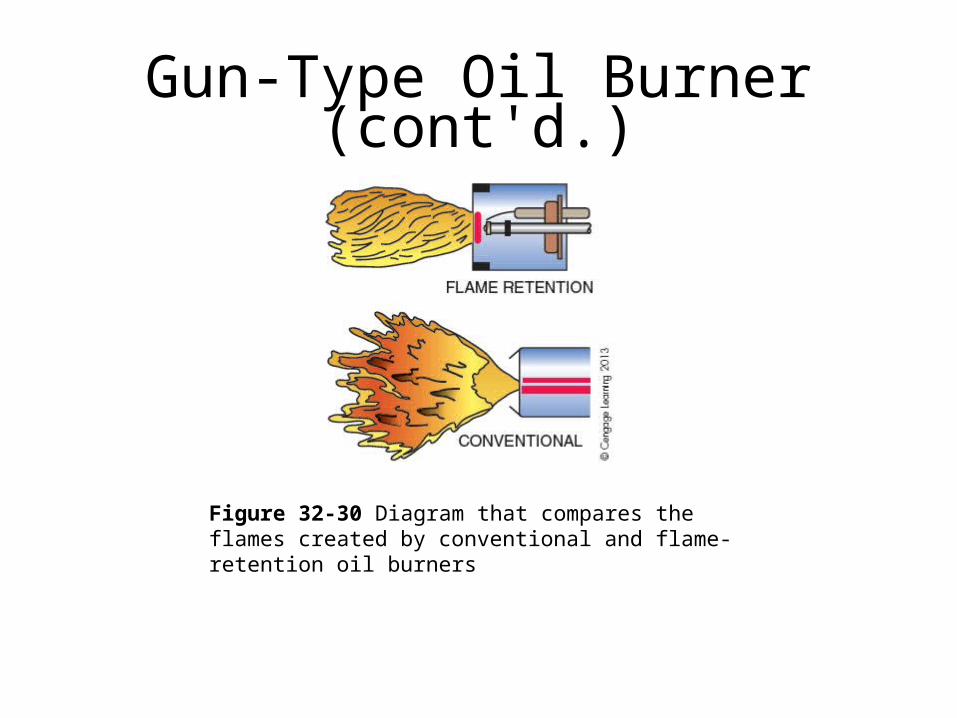
Figure 32-30 Diagram that compares the flames created by conventional and flame-retention oil burners

Oil Furnace Wiring Diagrams• Includes wiring for the fan, the oil burner
primary, and the 24-volt control circuits• The limit switch is a safety that passes
power to the primary control• On a call for heat, power is passed to the
ignition transformer, burner motor, and fuel valve
• The safety device will shut the burner down in case of a problem
Safety Controls• Stack switch safety control
– Positioned in the flue pipe– Bimetal heated by combustion flue gases
• Hot contacts allow the burner motor to continue operation
• Cold contacts allow current to flow through safety switch heater
• Cad cell safety control– When the burner fires, the cad cell senses light
and its resistance drops, causing the triac to open

Combustion Chamber• Atomized oil is burned in suspension in
the combustion chamber• Oil that is not completely ignited will hit
the chamber walls and condense– Oil vapor hitting chamber walls and
condensing will lower combustion efficiency
• The burner must be matched to the chamber
• The chamber is a box to contain the fire

Heat Exchanger• Transfers heat from combustion to the air
that is circulated to heat the structure– Separates flue gases from the air circulated
to heat the structure– Should be inspected for cracks during
normal service• Most state codes prohibit repairing cracks by
welding
• Correct airflow across the heat exchanger is important
Condensing Oil Furnace• More efficient than conventional furnaces• Combustion system includes:
– Burner and related components, combustion chamber, as many as three heat exchangers, and vent fan and pipe
• In third heat exchanger, temperatures are reduced below dew point
• Heated air circulation system includes:– Blower fan, housing, motor, plenum, and
duct system

Service Procedures• Pumps: connect vacuum and pressure
gauges to pump– Pressure should be 0 psig if tank is above
burner– If tank is below burner, pressure should not be
lower than 17 in. Hg• 1 in. Hg for each foot of vertical lift• 1 in. Hg for every 10 feet of horizontal run
– Nozzle pressure should be steady at 100 psig or 140 psig depending on the burner assembly

Service Procedures (cont'd.)• Burner motors: press reset button to see
if motor will start– Check for voltage between orange and
white wires of the primary control• If there is no voltage, the primary control needs
to be checked
– Check for voltage between black and white wires on the burner motor
• If there is voltage and the motor does not turn, the motor is defective

Service Procedures (cont'd.)• Nozzles: do not try to repair a nozzle
– Nozzles are often replaced annually– Always make certain to use the correct
nozzle size– Use proper tools to remove nozzles– Overheating nozzles can result in oil
breakdown– After-drip can result in the nozzle getting
clogged

Service Procedures (cont'd.)• Ignition system
– Transformer• Turn power off and swing the transformer back• Shut off fuel supply to the burner• Restore power to the burner• Check for output voltage of 10,000 volts
– Electrodes• Ensure the spark gap settings for proper position• Check insulation for cracks• Keep electrodes clean

Combustion Efficiency• Areas to test for proper combustion:
– Draft: determines rate at which flue gases pass through the furnace
• Too much increases stack temperature, too little can result in pressure and smoke
– Smoke: indicates incomplete combustion and fuel waste
– Net stack temperature– CO
2: good indicator of combustion efficiency
• Low reading indicates fuel oil has not burned completely
Summary
• Oil-fired furnaces are made up of heat-producing and heat-distributing systems
• No. 2 fuel oil produces about 140,000 Btu/gal
• Fuel oil must be atomized before combustion

Summary (cont’d.)
• Typical oil burner contains a motor, blower, fuel pump, nozzle, electrodes and primary control
• Nozzles rated by flow rate, angle, and spray pattern
• Ignition transformers and electronic igniters provide the high voltage needed for spark ignition

Summary (cont’d.)
• The primary control controls burner operation and safety functions of the system
• Primary controls can use cad cells or stack relays
• The resistance of a cad cell decreases as the amount of light sensed increases

Summary (cont’d.)
• The stack relay responds to the stack temperature
• Condensing furnaces are more efficient than conventional furnaces

For more information please contact
Mark T. Weber, M.Ed, CMHE
At
North Seattle Community College
WWW.NorthSeattle.edu