Embed Size (px)
Citation preview
Online Generation of Humanoid Walking Motion based on a Fast
Generation Method of Motion Pattern that Follows Desired ZMP
Koichi Nishiwaki1, Satoshi Kagami2, Yasuo Kuniyoshi1, Masayuki Inaba1, Hirochika Inoue1
1The University of Tokyo, Tokyo, Japan, fnishi,kuniyosh,inaba,[email protected],2National Institute of Advanced Industrial Science and Technology, Tokyo, Japan, [email protected]
Abstract
This paper presents an e�cient online method to
generate humanoid walking motions that satisfy de-
sired upper body trajectories while simultaneously
carrying objects. A fast motion pattern genaration
technique that follows the desired ZMP is adopted. In
order to satisfy the control input given online, subse-
quent motion patterns are updated and connected sta-
bly to the old ones while executing. During the cre-
ation of motion trajectories online, the commanded
motion parameters are checked and modi�ed auto-
matically considering the performance limitations of
the hardware. As an example application, we have
implemented a one step cycle control system on the
Humanoid H7. Experiments controlling the upper
body motion and walking direction using a joystick
interface are explained to demonstrate the validity of
the proposed method.
1 Introduction
Humanoid robots are considered to have the advan-
tage of working in environments designed for real hu-
mans. In order to exibly operate in environments
where humans live and work, the capability of chang-
ing its motion online according to sensory informa-
tion or control commands is important since the en-
vironment is not well modeled and always changing.
Of course, it also applies to walking motion.
On the other hand, biped humanoids have more com-
plicated dynamics model than biped walking robots
that are developed primarily to verify walking theo-
ries. Because of the high cost of calculating the dy-
namics, walking on biped humanoids has been real-
ized by constructing a dynamically-stable trajectory
in advance, and executing it[1, 2, 3].
In recent years, several researches that realize on-
line control of humanoid walking were reported. Se-
tiawan, et al. realized online control of forward
and backward walking by connecting motion pat-
terns generated in advance[4]. Yokoi, et al. real-
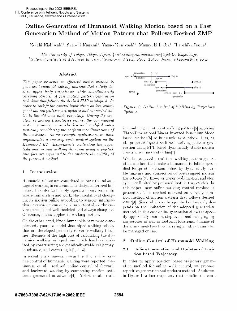
updateexecution
genearation
input
time
input
input
input
genearation
genearation
genearation
t t
(Traj. 1)
(Traj. 2)
(Traj. 3)
(Traj. n)
1 2
Figure 1: Online Control of Walking by Trajectory
Updates
ized online generation of walking pattern[5] applying
Three-Dimensional Linear Inverted Pendulum Mode
based method[6] to humanoid type robot. Lim, et
al. proposed \quasi-realtime" walking pattern gen-
eration using FFT based dynamically stable motion
construction method online[7].
We also proposed a real-time walking pattern gener-
ation method that make a humanoid to follow spec-
i�ed footprint locations online by dynamically sta-
ble mixture and connection of pre-designed motion
trajectories[8]. However upper body motion and step
cycle are limited by prepared motion trajectories. In
this paper, new online walking control method is
presented. This method is based on a fast genera-
tion method of motion pattern that follows desired
ZMP[9]. Since what can be speci�ed online only de-
pends on the limitation of the adopted generation
method, in this case online generation allows to spec-
ify upper body motion, step cycle, and swinging leg
trajectories as well as footprint locations. Change of
dynamics model such as carrying an object can also
be managed online.
2 Online Control of Humanoid Walking
2.1 Online Generation and Updates of Posi-
tion based Trajectory
In order to apply position based trajectory gener-
ation method for online walk control, we propose
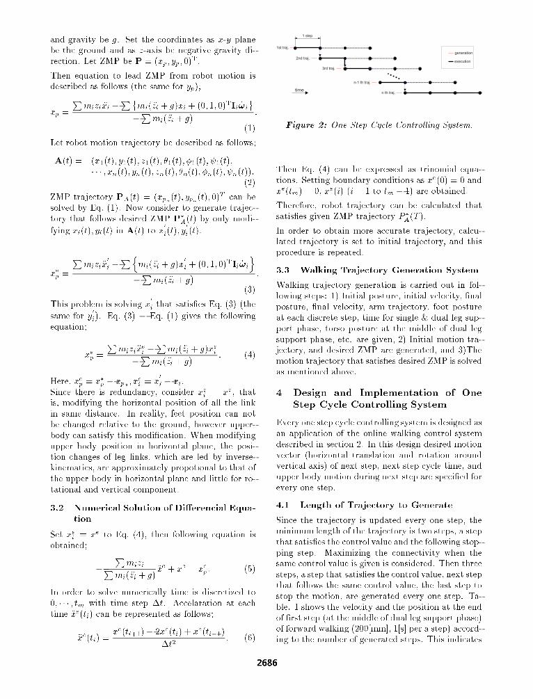
repetitive generation and updates method. As shown
in Figure 1, a �rst trajectory that satis�es the con-
trol value at that moment is generated and walking
motion starts by executing it (Traj. 1). During the
execution, at t1 generaton of a trajectory (Traj. 2)
that connects to the executing trajectory (Traj. 1)
at t2 and satis�es the control value at t1 starts. Here
t2 is decided by adding estimated upper limit of gen-
eration time and some time margin to t1. Then at t2Traj. 1 is connected to Traj. 2 smoothly. Repeating
this procedure walking motion that follows control
values given online is realized witout stopping. All
the trajectories are designed to make a robot stably
stop if executed to the last. Owing to this design
the robot will stop safely executing the rest of the
trajectory when updates of trajectory fails for some
reason, unless the change of the environment a�ects
the robot motion.
In order to apply a motion trajectory generation
method to this online update system, following char-
acteristics are required;
� Time for generation is quick enuough,
� It is possible to generate a trajectory that con-
nects to a speci�ed motion state smoothly,
� It can guarantee that the generated trajecto-
ries are executable on the real robot considering
robot performance constraints as well as dynam-
ical stability constraints.
2.2 Calculation Time
It is necesarry for generation time to be shorter than
its motion time in order to update the motion con-
tinuously, and less generation time achieves less la-
tency from the control input. The adopted gener-
ation method includes iterative calculation to gain
higher accuracy. The calculation time is proportional
to the motion time and the number of iteration. It
takes 3 to 6 times iteration to obtain the motion the
average ZMP error of which is less than 2.0[mm].
When 6 times iteration is required, it takes about
2.4% of its motion time to generate the dynamically
stable trajectory on the computer inside the robot
(Humanoid H7: dual Pentium III 1.1[GHz], calcu-
lation step: 50[ms]). We implemented the method
in the realtime layer of RT-Linux[10] and made it
possible to limit the number of iteration in order to
guarantee the upper limit of calculation time.
2.3 Smooth Connection to the Previous Tra-
jectory
The adopted generation method changes horizontal
position of upper body trajectory from initially given
motion in order to satisfy desired ZMP, but it does
not change the position and the velocity at the ends
of a trajectory from the initial ones. When a initial
trajectory of connecting motion is designed, the po-
sition and velocity at the connecting time are set to
the same as the connected ones. Then the position
and velocity will be the same at a connecting point.
2.4 Validation of Realizability of Generated
Motion Trajectories
Since this online generation method can generate
various walking motion and real robots have many
performance constraints, realizability on a real robot
becomes a problem. Following performance con-
straints are taken into consideration in this paper;
� Existence of the solution for inverse-kinematics
of legs,
� Limitation of joint angle range,
� Limitation of joint angle velocity,
� Collision between links.
Dynamically stable motion generation time takes
most of online generation time. If it becomes evident
that the generated trajectory can not be realized on
a real robot after generation, it is impossible to re-
generate a trajectory that connects to the same time.
In order to raise the probability that the trajectory
can be executed, validation of trajectory is carried
out in the following two steps;
� Heuristic limitation of paremeters that are used
for trajectory generation,
� Validation of generated trajectory.
The details of this process is described in section 4.2.
3 Generation of Walking Trajectory that
Follows Desired ZMP
In this section the fast dynamically stable walking tr-
jectory generation method we adopted is explained.
In general, ZMP trajectory can be analytically led
from the robot motion trajectory, however leading
robot trajectory that satis�es given ZMP trajectory
analitically is di�cult, since it has to solve non-
linear, interfered 2nd order di�erencial equation with
joint constraints. In this section, a fast generation
method of walking trajectory that follows given ZMP
trajectory by modifying horizontal torso trajectory
from given initial trajectory is explained.
3.1 Linearlize and Decouple the Dynamic
Equation about ZMP
Let ith robot link position, mass, inertia tensor, an-
gular velocity vector be ri = (xi; yi; zi)T;mi; Ii; !i,
and gravity be g. Set the coordinates as x-y plane
be the ground and as z-axis be negative gravity di-
rection. Let ZMP be P = (xp; yp; 0)T.
Then equation to lead ZMP from robot motion is
described as follows (the same for yp);
xp =
Pmizi �xi �
P�mi( �zi + g)xi + (0; 1; 0)TIi _!i
�Pmi( �zi + g)
:
(1)
Let robot motion trajectory be described as follows;
A(t) = (x1(t); y1(t); z1(t); �1(t); �1(t); 1(t);
� � � ; xn(t); yn(t); zn(t); �n(t); �n(t); n(t)):(2)
ZMP trajectory PA(t) = (xpa(t); ypa(t); 0)T can be
solved by Eq. (1). Now consider to generate trajec-
tory that follows desired ZMP P�
A(t) by only modi-
fying xi(t); yi(t) in A(t) to x0
i(t); y
0
i(t).
x�
p=
Pmizi�x
0
i�Pn
mi( �zi + g)x0
i+ (0; 1; 0)TIi _!i
o
�Pmi( �zi + g)
:
(3)
This problem is solving x0
ithat satis�es Eq. (3) (the
same for y0
i). Eq. (3) � Eq. (1) gives the following
equation;
xep=
Pmizi�x
e
i�Pmi( �zi + g)xe
i
�Pmi( �zi + g)
: (4)
Here, xep= x�
p� xpa ; x
e
i= x
0
i� xi.
Since there is redundancy, consider xei= xe, that
is, modifying the horizontal position of all the link
in same distance. In reality, feet position can not
be changed relative to the ground, however upper-
body can satisfy this modi�cation. When modifying
upper body position in horizontal plane, the posi-
tion changes of leg links, which are led by inverse-
kinematics, are approximately propotional to that of
the upper body in horizontal plane and little for ro-
tational and vertical component.
3.2 Numerical Solution of Di�erencial Equa-
tion
Set xei= xe to Eq. (4), then following equation is
obtained;
�
PmiziP
mi( �zi + g)�xe + xe = xe
p: (5)
In order to solve numerically time is discretized to
0; � � � ; tm with time step �t. Accelaration at each
time �xe(ti) can be represented as follows;
�xe(ti) =xe(ti+1)� 2xe(ti) + xe(ti�1)
�t2: (6)
generation
execution
1st traj.
2nd traj.
3rd traj.
n-1 th traj.
n th traj.
1 step
time
Figure 2: One Step Cycle Controlling System.
Then Eq. (4) can be expressed as trinomial equa-
tions. Setting boundary conditions as xe(0) = 0 and
xe(tm) = 0, xe(i) (i = 1 to tm � 1) are obtained.
Therefore, robot trajectory can be calculated that
satis�es given ZMP trajectory P �
A(T ).
In order to obtain more accurate trajectory, calcu-
lated trajectory is set to initial trajectory, and this
procedure is repeated.
3.3 Walking Trajectory Generation System
Walking trajectory generation is carried out in fol-
lowing steps: 1) Initial posture, initial velocity, �nal
posture, �nal velocity, arm trajectory, foot posture
at each discrete step, time for single & dual leg sup-
port phase, torso posture at the middle of dual leg
support phase, etc. are given, 2) Initial motion tra-
jectory, and desired ZMP are generated, and 3)The
motion trajectory that satis�es desired ZMP is solved
as mentioned above.
4 Design and Implementation of One
Step Cycle Controlling System
Every one step cycle controlling system is designed as
an application of the online walking control system
described in section 2. In this design desired motion
vector (horizontal translation and rotation around
vertical axis) of next step, next step cycle time, and
upper body motion during next step are speci�ed for
every one step.
4.1 Length of Trajectory to Generate
Since the trajectory is updated every one step, the
minimum length of the trajectory is two steps, a step
that satis�es the control value and the following stop-
ping step. Maximizing the connectivity when the
same control value is given is considered. Then three
steps, a step that satis�es the control value, next step
that follows the same control value, the last step to
stop the motion, are generated every one step. Ta-
ble. 1 shows the velocity and the position at the end
of �rst step (at the middle of dual leg support phase)
of forward walking (200[mm], 1[s] per a step) accord-
ing to the number of generated steps. This indicates
Table 1: State of Motion at the End of First Step
num. of position velocity
steps x[mm] y[mm] x[mm/s] y[mm/s]
2 96.560654 -1.425083 343.660 304.362
3 98.659909 -2.316348 352.912 301.460
4 98.738370 -2.289558 353.323 301.537
5 98.741380 -2.290479 353.343 301.534
6 98.741504 -2.290453 353.345 301.534
z
x
y
right foot
left foot
forw
ard
a
w
a
-a
(landing)
z
x
y
right foot
left foot
forw
ard
previousplan
b
P
Q
Q’
A
B
(a) (b)
Figure 3: Limitation of Landing Position. (a) Rel-
ative to the supporting leg foot position, (b) Relative
to the previously planned position.
there is no need to generate more than three steps in
order to maximize the connectivity.
4.2 Limitation of Parameters and Validation
of Trajectory
As mentioned in section 2.4, in order to construct
realizable trajectory, limitation of parameters before
trajectory generation and validation of trajectory af-
ter generation are carried out.
Limitation of parameters given to the trajectory gen-
eration system is performed in following steps;
1. Landing position is limited in the area shown in
Figure 3(a) relative to the position of supporting
leg foot, so that the foot can be reached. It is
circle area whose center is neutral landing posi-
tion and it is also limited by the sideward width.
The narrowest is the neutral landing position.
2. Limit the change of the �rst step landing posi-
tion of a new trajectory from the planned posi-
tion in the previous (connected) trajectory. Fig-
ure 3(b) is the situation to generate a new tra-
jectory that connects to old one when left and
right feet are at A and B respectively. The next
h
a
l
Figure 4: Limitation of Torso Height.
Figure 5: Collision detection between the links of
two legs. [11]
landing position was planned to be P in the pre-
vious (executing) trajectory, then if the �rst step
landing position of new trajectory is set to Q, it
is modi�ed to Q0.
It reduces the discontinuity of the acceleration
at the connecting point. Reduction of the dis-
continuity contributes to the little change of
ZMP at that point.
3. Limit minimum sideward distance of the land-
ing position from the foot of supporting leg in
order to prevent collision of links between two
legs. The minimum distance is function of rela-
tive rotational angle between two feet.
4. Limit the maximum hip joint height from the
ankle joint of the same leg (h) topl20 � a2 (Fig-
ure 4). This helps to increase probability of ex-
istence of solution for inverse kinematics and to
reduce the maximum velocity of knee joints.
Validation after trajectory generation is carried out
for the following points;
� Range limitation of leg joint angle,
� Limitation of leg joint angle velocity,
� Collision between leg links.
Footprint Planner
motionvector
Walking Pattern Generator
request footprint
Real-timeLayer
Trajectory Manager
request trajectory
OnlineBalancerdesired leg
posture & ZMPmeasured ZMP,torso inclination
MotorServo
goalangle
goal angle (arms, neck)
current angle
controlvalue
Hardware
DynamicsModel
&armmotion & torso
posture
Figure 6: Online Walking Control System.
A fast mimimum distance calculation system[11] is
adopted for collision detection (Figure 5). We set
some safety margin for each check, because the tra-
jectories are modi�ed by sensor feedback when exe-
cuted. If a trajectory is judged not realizable, the
update is abandoned and the robot stops executing
the rest of the current trajectory.
4.3 Calculation Time
The step cycle can be changed from 0.7 to 2.0[s] in
this implementation. Then the longest trajectory is
5.2[s]. (Last one step is always 1.2[s].) And the max-
imum calculation time for generating the trajectory
was about 215[ms]. The time for collision check was
15 to 25[ms] (Sampling time is 50[ms] and the num-
ber of checked pairs is reduced to 19 considering the
possibility of collision.) Calculation time for other
parts is negligible comparing with these two. Start
time of generation is set to 250[ms] before the start
of execution.
4.4 Software System
The walking control system is implemented in the re-
altime layer of RT-Linux (Figure 6). Foorprint Plan-
ner is a module that generates footprint locations
from desired torso motion. Walking Pattern Gener-
ator is the module that generates three step realiz-
able trajectories. Generated trajectories are stored
in Trajectory Manager, and this module updates the
control value of Motor Servo and Online Balancer
modules periodically (1[ms] cycle). It also notify the
Walking Pattern Generator of the time for the next
generation.
4.5 Controlling Experiment using Joystick
Interface
Controlling system with joystick interface is imple-
mented as an application. Joystick is connected to
a PC outside, and commands are sent via wireless
LAN. Forward and sideward axes and twisting axis
of the joystick are assigned to the desired translation
and rotation of torso motion. Desired torso posture
is controlled by combination of thrust lever and but-
tons. Several arm postures are also assigned to but-
tons. The robot successfully walked while changing
its arm and torso posture (Figure 7, 8, 9). Chang-
ing dynamics model online, walking with shaking a
1[kg]-bottle was also realized (Figure 10).
5 Conclusion
Online walking control method by updating posi-
tion based trajectory is proposed. A fast generation
method of motion pattern that follows desired ZMP
was explained. The method is suitable for dynami-
cally stable trajectory generation for online walking
control. Performance constraints as well as dynam-
ics constraints are taken into consideration in the
control sysytem. One step cycle controlling system
was implemented, and controlling experiments with
joystick interface showed the validity of the method.
Utilizing the modi�cation caused by sensor feedback
for later trajectory generation is the next reserch
topic.
References
[1] Kazuo Hirai. Current and future perspective of
Honda humanoid robot. In In Proceeding of 1997
IEEE/RSJ International Conference on Intelligent
Robots and Systems (IROS'97), pp. 500{508, 1997.
[2] Jin'ichi Yamaguchi, Sadatoshi Inoue, Daisuke
Nishino, and Atsuo Takanishi. Development of a
bipedal humanoid robot having antagonistic driven
joints and three dof trunk. In Proc. of the 1998
IEEE/RSJ Int. Conf. on Intelligent Robots and Sys-tems, pp. 96{101, 1998.
[3] Ken'ichirou Nagasaka, Masayuki Inaba, and Hi-
rochika Inoue. Walking pattern generation for a hu-
manoid robot based on optimal gradient method. In
Proc. of 1999 IEEE Int. Conf. on Systems, Man, andCybernetics, 1999.
[4] Samuel Agus Setiawan, Sang Ho Hyon, Jin'ichi Ya-
maguchi, and Atsuo Takanishi. Physical interaction
between human and a bipedal humanoid robot { real-
ization of human-follow walking {. In Proceddings of
the 1997 IEEE International Conference on Roboticsand Automation, pp. 361{367, 1999.
[5] Kazuhito Yokoi, Fumio Kanehiro, Kenji Kaneko,
Kiyoshi Fujiwara, Shuji Kajita, and Hirohisa
Hirukawa. A honda humanoid robot controlled by aist
software. In Proceddings of the IEEE-RAS Interna-tional Conference on Humanoid Robots, pp. 259{264,
2001.
[6] Shuji Kajita, Osamu Matsumoto, and Muneharu
Saigo. Real-time 3D walking pattern generation for
Figure 7: Online Walking Control. (Changing Torso Posture around Roll Axis.)
Figure 8: Online Walking Control. (Changing Torso Posture around Pitch Axis.)
Figure 9: Online Walking Control. (Changing Torso Posture around Yaw Axis.)
Figure 10: Online Walking Control. (Shaking a Bottle (about 1 [kg]).)
a biped robot with telescopic legs. In Proceddings of
the 2001 IEEE International Conference on Robotics
and Automation, pp. 2299{2306, 2001.
[7] Hun-ok Lim, Yoshiharu Kaneshima, and Atsuo
Takanishi. Online Walking Pattern Generation for
Biped Humanoid Robot with Trunk. In Proc. of IEEE
International Conference on Robotics and Automa-
tion, pp. 3111{3116, 2002.
[8] K. Nishiwaki, T. Sugihara, S. Kagami, M. Inaba, and
H. Inoue. Realtime generation of humanoid walking
trajectory by mixture and connection of pre-designed
motions { online control by footprint speci�cation {.
In Proc. of International Conference on Robotics and
Automation (ICRA'01), pp. 4110{4115, 2001.
[9] S. Kagami, K. Nishwiaki, T. Kitagawa, T. Sugihara,
M. Inaba, and H. Inoue. A fast generation method
of a dynamically stable humanoid robot trajectory
with enhanced zmp constraint. In Proc. of IEEE In-
ternational Conference on Humanoid Robotics (Hu-manoid2000), 2000.
[10] Michael Barabanov. A linux-based real-time operat-
ing system. Master's thesis, New Mexico Institute of
Mining and Technology, 1997.
[11] James Ku�ner, Koichi Nishiwaki, Satoshi Kagami,
Yasuo Kuniyoshi, Masayuki Inaba, and Hirochika In-
oue. Self-collision detection and prevention for hu-
manoid robots. In Proc. of International Conference
on Robotics and Automation (ICRA'02), pp. 2265{
2270, 2002.