Embed Size (px)
Citation preview
OREGONMANUFACTURED
DWELLINGAND PARK
SPECIALTY CODE
2002 EDITION
Published by the Oregon Manufactured Housing Association andOregon Building Codes Division, Department of Consumer and Business Services
Introductory
Chapter OneAdministrative
Chapter TwoAlternate DwellingUses
Chapter ThreeInstallations
Acknowledgements………………………Foreward ……………..……………………
General……………………………………..Authority…………………………………...Mfg. Dwellings Sold “As Is”…………….Other Applicable Standards…………….Fees…………………………………………Plans………………………………………...Permits……………………………………...Inspections………………………………...Insignias and Labels……………………..Certifications………………………………Licensing Requirements………………...Violations and Penalties…………………Appeals……………………………………..
Alternate Uses…………………………….Change of Occupancies…………………Accessibility……………………………….
General……………………………………..Geographical Requirements……………Chassis……………………………………..Site and Stand Preparation……………..Approved Materials………………...…….Foundation Pier Spacing………………..Foundation Heights………………………Foundation Construction………………..Under Floor Enclosures ………………...Under Floor Ventilation and Access…..Marriage Line Connection and Seal..….Access and Egress……………………….Tables……………………………………….
12
346677
10141920212425
272929
31323838404547485559616467
OREGON MANUFACTURED DWELLING AND PARKSPECIALTY CODE
Table of Contents
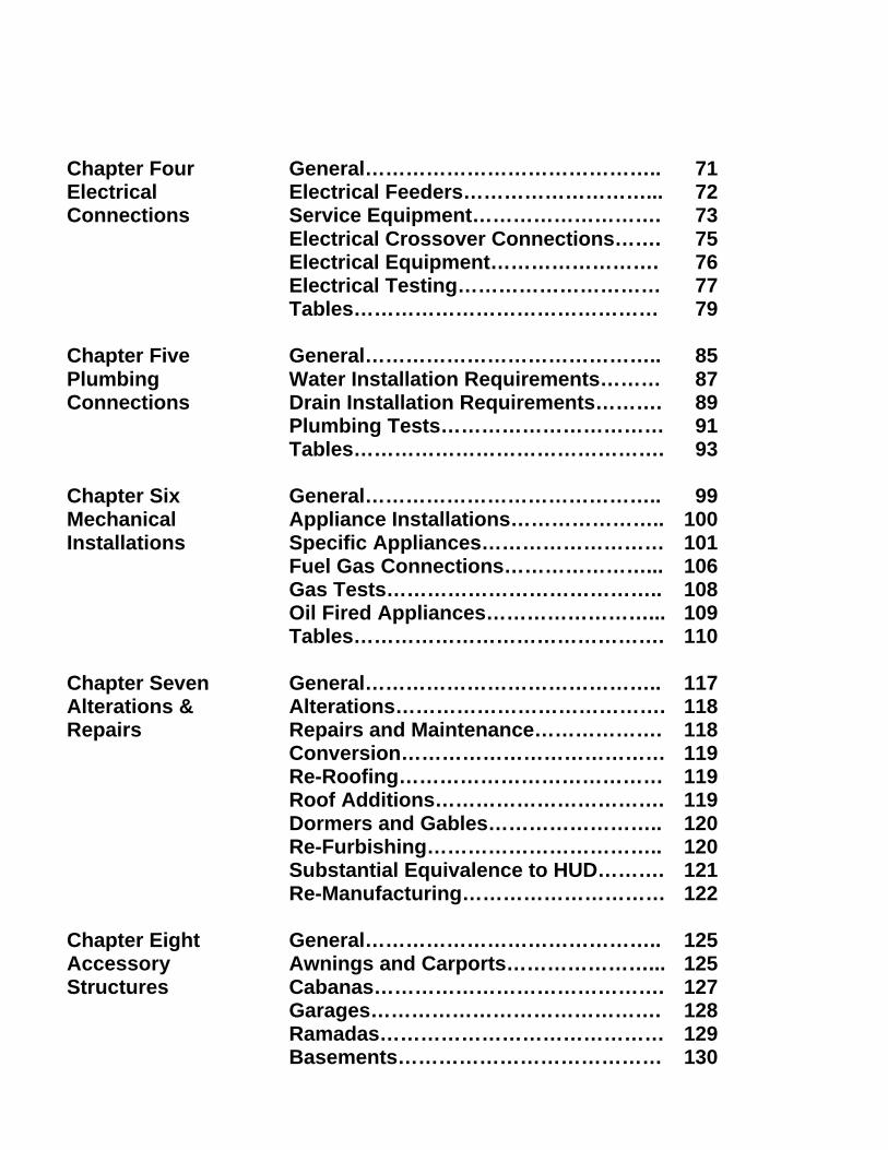
Chapter FourElectricalConnections
Chapter FivePlumbingConnections
Chapter SixMechanicalInstallations
Chapter SevenAlterations &Repairs
Chapter EightAccessoryStructures
General……………………………………..Electrical Feeders………………………...Service Equipment……………………….Electrical Crossover Connections…….Electrical Equipment…………………….Electrical Testing…………………………Tables………………………………………
General……………………………………..Water Installation Requirements………Drain Installation Requirements……….Plumbing Tests……………………………Tables……………………………………….
General……………………………………..Appliance Installations…………………..Specific Appliances………………………Fuel Gas Connections…………………...Gas Tests…………………………………..Oil Fired Appliances……………………...Tables……………………………………….
General……………………………………..Alterations………………………………….Repairs and Maintenance……………….Conversion…………………………………Re-Roofing…………………………………Roof Additions…………………………….Dormers and Gables……………………..Re-Furbishing……………………………..Substantial Equivalence to HUD……….Re-Manufacturing…………………………
General……………………………………..Awnings and Carports…………………...Cabanas…………………………………….Garages…………………………………….Ramadas……………………………………Basements…………………………………
71727375767779
8587899193
99100101106108109110
117118118119119119120120121122
125125127128129130
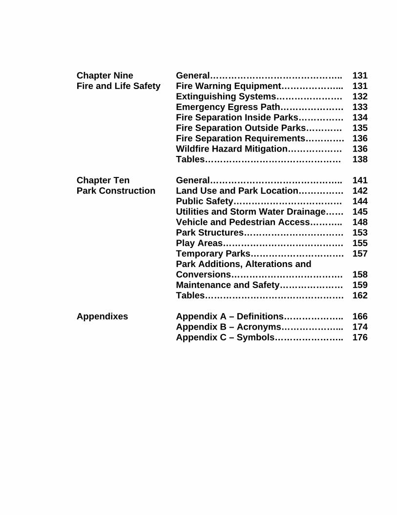
Chapter NineFire and Life Safety
Chapter TenPark Construction
Appendixes
General……………………………………..Fire Warning Equipment………………...Extinguishing Systems………………….Emergency Egress Path…………………Fire Separation Inside Parks……………Fire Separation Outside Parks…………Fire Separation Requirements………….Wildfire Hazard Mitigation………………Tables………………………………………
General……………………………………..Land Use and Park Location……………Public Safety………………………………Utilities and Storm Water Drainage……Vehicle and Pedestrian Access………..Park Structures……………………………Play Areas………………………………….Temporary Parks………………………….Park Additions, Alterations andConversions……………………………….Maintenance and Safety…………………Tables……………………………………….
Appendix A – Definitions………………..Appendix B – Acronyms………………...Appendix C – Symbols…………………..
131131132133134135136136138
141142144145148153155157
158159162
166174176
1
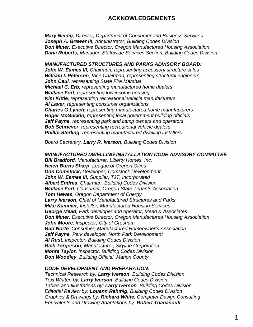
ACKNOWLEDGEMENTS
Mary Neidig, Director, Department of Consumer and Business ServicesJoseph A. Brewer III, Administrator, Building Codes DivisionDon Miner, Executive Director, Oregon Manufactured Housing AssociationDana Roberts, Manager, Statewide Services Section, Building Codes Division
MANUFACTURED STRUCTURES AND PARKS ADVISORY BOARD:John W. Eames III, Chairman, representing accessory structure salesWilliam I. Peterson, Vice Chairman, representing structural engineersJohn Caul, representing State Fire MarshalMichael C. Erb, representing manufactured home dealersWallace Fort, representing low income housingKim Kittle, representing recreational vehicle manufacturersAl Laver, representing consumer organizationsCharles G Lynch, representing manufactured home manufacturersRoger McGuckin, representing local government building officialsJeff Payne, representing park and camp owners and operatorsBob Schriever, representing recreational vehicle dealersPhillip Sterling, representing manufactured dwelling installers
Board Secretary, Larry R. Iverson, Building Codes Division
MANUFACTURED DWELLING INSTALLATION CODE ADVISORY COMMITTEEBill Bradford, Manufacturer, Liberty Homes, Inc.Helen Burns Sharp, League of Oregon CitiesDon Comstock, Developer, Comstock DevelopmentJohn W. Eames III, Supplier, TJT, IncorporatedAlbert Endres, Chairman, Building Codes DivisionWallace Fort, Consumer, Oregon State Tenants AssociationTom Hewes, Oregon Department of EnergyLarry Iverson, Chief of Manufactured Structures and ParksMike Kammer, Installer, Manufactured Housing ServicesGeorge Mead, Park developer and operator, Mead & AssociatesDon Miner, Executive Director, Oregon Manufactured Housing AssociationJohn Moore, Inspector, City of GreshamBud Norte, Consumer, Manufactured Homeowner’s AssociationJeff Payne, Park developer, North Park DevelopmentAl Rust, Inspector, Building Codes DivisionRick Torgerson, Manufacturer, Skyline CorporationMonte Taylor, Inspector, Building Codes DivisionDon Woodley, Building Official, Marion County
CODE DEVELOPMENT AND PREPARATION:Technical Research by: Larry Iverson, Building Codes DivisionText Written by: Larry Iverson, Building Codes DivisionTables and Illustrations by: Larry Iverson, Building Codes DivisionEditorial Review by: Louann Rahmig, Building Codes DivisionGraphics & Drawings by: Richard White, Computer Design ConsultingEquivalents and Drawing Adaptations by: Robert Thanasouk
2
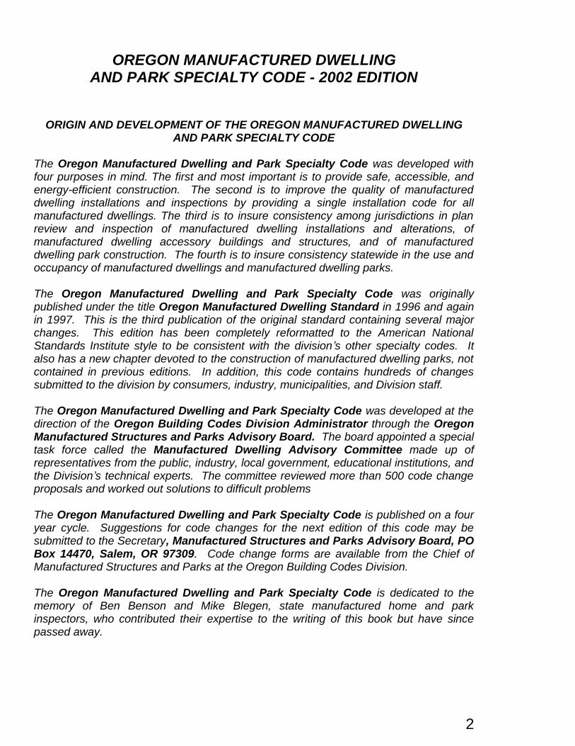
OREGON MANUFACTURED DWELLINGAND PARK SPECIALTY CODE - 2002 EDITION
ORIGIN AND DEVELOPMENT OF THE OREGON MANUFACTURED DWELLINGAND PARK SPECIALTY CODE
The Oregon Manufactured Dwelling and Park Specialty Code was developed withfour purposes in mind. The first and most important is to provide safe, accessible, andenergy-efficient construction. The second is to improve the quality of manufactureddwelling installations and inspections by providing a single installation code for allmanufactured dwellings. The third is to insure consistency among jurisdictions in planreview and inspection of manufactured dwelling installations and alterations, ofmanufactured dwelling accessory buildings and structures, and of manufactureddwelling park construction. The fourth is to insure consistency statewide in the use andoccupancy of manufactured dwellings and manufactured dwelling parks.
The Oregon Manufactured Dwelling and Park Specialty Code was originallypublished under the title Oregon Manufactured Dwelling Standard in 1996 and againin 1997. This is the third publication of the original standard containing several majorchanges. This edition has been completely reformatted to the American NationalStandards Institute style to be consistent with the division’s other specialty codes. Italso has a new chapter devoted to the construction of manufactured dwelling parks, notcontained in previous editions. In addition, this code contains hundreds of changessubmitted to the division by consumers, industry, municipalities, and Division staff.
The Oregon Manufactured Dwelling and Park Specialty Code was developed at thedirection of the Oregon Building Codes Division Administrator through the OregonManufactured Structures and Parks Advisory Board. The board appointed a specialtask force called the Manufactured Dwelling Advisory Committee made up ofrepresentatives from the public, industry, local government, educational institutions, andthe Division’s technical experts. The committee reviewed more than 500 code changeproposals and worked out solutions to difficult problems
The Oregon Manufactured Dwelling and Park Specialty Code is published on a fouryear cycle. Suggestions for code changes for the next edition of this code may besubmitted to the Secretary, Manufactured Structures and Parks Advisory Board, POBox 14470, Salem, OR 97309. Code change forms are available from the Chief ofManufactured Structures and Parks at the Oregon Building Codes Division.
The Oregon Manufactured Dwelling and Park Specialty Code is dedicated to thememory of Ben Benson and Mike Blegen, state manufactured home and parkinspectors, who contributed their expertise to the writing of this book but have sincepassed away.
3
CHAPTER ONEADMINISTRATIVE
1-1 General1-2 Authority1-3 Mfg. Dwellings Sold “As Is”1-4 Other Applicable Standards1-5 Fees1-6 Plans1-7 Permits1-8 Inspections1-9 Insignias and Labels1-10 Certifications1-11 Licensing Requirements1-12 Violations and Penalties1-13 Appeals
1-1 General.1-1.1 Title. These provisions shall beknown as the Oregon ManufacturedDwelling and Park Specialty Code,2002 Edition, may be cited as such,and will be referred to herein as “thiscode” or the “MD&P”. This code shallremain in the public domain and maynot be copyrighted. The public iswelcome to make copies for their use.
1-1.2 Purpose. This code is intended toprovide statewide standards for theprotection of life, limb, health, property,and for the safety and welfare of theconsumer, general public, and theowners and occupants of manufactureddwellings. The requirements of this codemay be exceeded by a homeowner,contractor, dealer, distributor, financialinstitution, or manufacturer, but nojurisdiction may require a person toexceed this code except wherespecifically permitted within this code.
1-1.3 Scope. This code applies to thesiting, installation, alteration, repair,construction, addition, conversion, use,and occupancy of manufactureddwellings, accessory buildings,accessory structures, mobile homeparks, and manufactured dwelling parks
in Oregon as authorized by ORS446.062 and 446.155 and the following:(a) When city, county or state rules,regulations, standards, ordinances, orcodes refer to the OregonManufactured Dwelling Standard(OMDS) or Oregon AdministrativeRule (OAR) 918-600, it shall beunderstood that those documents arereferring to this code, the 2002 OregonManufactured Dwelling and ParkSpecialty Code;(b) Except where otherwise noted,illustrations (figures) used in this codeare examples of typical methods ofconstruction and should not beconstrued as the only method permittedby this code. Appendices used in thiscode are not adopted as part of thiscode and should be consideredinformational only. However, some ofthe information contained in theappendices are from other standards,rules, regulations, or statutes having thesame authority as this code. Highlightednotes and warnings are not part of thiscode but contain vital information for theuser. Tables contained in this code arepart of the code; and(c) Where differences occur between acity or county ordinance and this code,the provisions of this code shall apply.
1-1.4 Design Loads. Except as otherwisestated, the manufactured dwelling siting,foundation and installation requirementscontained in this code shall be based on thefollowing criteria:(a) Assumed soil bearing capacity of 1,000pounds per square foot (4880 kgs per sq. m);(b) Minimum pier capacity of 4,000 pounds(1800 kgs),(c) Floor live load (LL)of 40 pounds per squarefoot (195.2 kgs per sq. m);(d) Floor dead load (DL) of 15 pounds persquare foot (73.2 kgs per sq. m);(e) Wall dead load (DL) of 10 pounds persquare foot (48.8 kgs per sq. m);(f) Roof live load (LL) of 30 pounds per squarefoot (146.4 kgs per sq. m);
4
(g) Roof dead load (LL) of 10 pounds persquare foot (48.8 kgs per sq. m);(h) Total manufactured dwelling LL and DL ,105 pounds per square foot (4.88 kgs per sq.m.);(I) Horizontal wind load of 15 pounds persquare foot (73.2 kgs per sq. m.);(j) Roof uplift of 9 pounds per square foot(43.92 kgs per sq. m.);(k) Deck live load (LL) of 40 pounds per squarefoot (195.2 kgs per sq. m);(l) Stairs live load (LL) of 40 pounds per squarefoot (195.2 kgs per sq. m);(m) Landing live load (LL) of 40 pounds persquare foot (195.2 kgs per sq. m);(n) Handrail live load (LL) of 200 pounds (976kgs per m) at any point in any direction; and(o) Guardrail live load (LL) of 50 pounds (244kgs per m) per lineal foot and 200 pounds (976kgs per m) at any point in any direction.
1-1.5 Not Applicable Provisions.Except where otherwise stated, thiscode is not applicable in certainsituations including, but not limited to,the following:(a) Installation of manufactureddwellings on land owned and occupiedby the federal government may not besubject to this code;(b) Construction of manufactureddwelling parks on tribal lands or on landowned and occupied by a tribal councilmay not be subject to this code;(c) Construction or installation ofprefabricated structures, modularbuilding, or modular homes regulatedunder ORS 455.010 and OAR 918-674;(d) Construction of site-built dwellingsexcept for cabanas or as indicated inthis code; and(e) Owner-built manufactured dwellings.
1-1.6 Conflicts. Where, in any specificcase, different sections of this codespecify different materials, methods ofconstruction or other requirements, themost restrictive shall govern. Wherethere is a conflict between a generalrequirement and a specific requirementin this code, the specific requirementshall apply. Where there is a conflict
between this code and any referencedstandard, this code shall apply. Wherethere is a conflict between this code andany local ordinance or regulation, thiscode shall apply. Where, in any specificcase, there is a conflict between thiscode and applicable Oregon RevisedStatutes, the applicable statute shallapply.
1-1.7 Code Changes. This specialtycode is reviewed and updated on aregular basis. Persons requesting codechanges may submit their request to theBuilding Codes Division on formssupplied by the Division. Code changerequests should be addressed to theSecretary of the ManufacturedStructures and Parks Advisory Board.To receive information on code changenotices and interpretations or to beplaced on the Division’s manufactureddwelling interested parties mailing listsend a written request to the Division’sMail Support Specialist. To subscribe tothe Division’s publication “Codelink”,send a written request to the Division’spublications editor. Codelink is alsoavailable on the Division’s WEB site at“http://www.cbs.state.or.us”.
1-2Authority1-2.1 Code Preemption. The BuildingCodes Division adopts this code underthe authority of ORS 446.062, 446.155,446.185, 446.200, 446.230, 446.240,446.400, and 455.040. This code is astatewide preemptive code, and is theminimum acceptable and maximumrequired in the state of Oregon. Exceptas provided in ORS 455.040 orspecifically referenced within this code,no municipality shall enforce any othercode, standard, rule, regulation, orordinance regarding the regulation ofmanufactured dwellings, manufactureddwelling parks, mobile home parks, andcombination parks in Oregon.
1-2.2 Enforcement. The Building CodesDivision has delegated the responsibilityof enforcing the requirements contained
5
in OAR 918-500, OAR 918-515, OAR918-520, ORS 446, ORS 455, and thiscode to certain municipalities. Themunicipality’s building official, as theauthority having jurisdiction, is herebyauthorized and directed to enforce all ofthe provisions of this code. With thisdelegation, and acting as an agent ofthe Division, the building official has theauthority to issue permits, review plans,perform inspections, investigateviolations, issue stop work orders, issuecitations, enforce the state’s labelingand licensing requirements, requirecorrections, and serve notice ofproposed civil penalty assessments.
1-2.3 Interpretation. The buildingofficial shall have the authority to renderinterpretations of this code. Suchinterpretations, rules and regulationsshall be in conformance with the intentand purpose of this code. When thebuilding official finds that the strict letterof this code is impractical for a specialsituation, the building official may accepta modification as long as themodification does not lessen the health,life safety, and fire safety requirementsintended by this code. Personsrequesting formal interpretations of thiscode shall submit their request in writingto the Division’s Chief of ManufacturedStructures and Parks. To receive copiesof code interpretations see the Division’sWEB page at“http://www.cbs.state.or.us”.
1-2.4 Energy ConservationEquivalents. When it is necessary todetermine that a manufactured dwellingis performing at a level greater orequivalent to the Oregon Energy Code,certification or verification of the home toany of the following shall be consideredequivalent and acceptable:(a) Equivalent U-value identified on themanufacturer’s heat loss certificate asrequired by 24 CFR 3280.510;(b) Super Good Cents (SGC) program;(c) Manufacturer’s Acquisition Program(MAP);
(d) Natural Choice program;(e) Earth Advantage Program;(f) Energy Star program;(g) Equivalent energy conservation orweatherization programs foundacceptable by the authority havingjurisdiction; or(h) A visual inspection of the retrofitinstallations of insulation, sealing, andventilation found acceptable to theauthority having jurisdiction.
1-2.5 Alternate Methods andMaterials. The provisions of this codeare not intended to limit the appropriateuse of materials, appliances, equipment,or methods of construction design notspecifically prescribed by this code. Thebuilding official may accept proposedalternate materials, appliances,equipment, or methods of design orconstruction if they are at leastequivalent to that prescribed in this codein suitability, quality, strength,effectiveness, fire resistance, durability,dimensional stability, safety andsanitation. Compliance with specificperformance-based provisions of thiscode, in lieu of a prescriptiverequirement, shall also be permitted asan alternate. This code also promotesthe use of recycled materials wheneverpossible as long as there are noadverse affects and the materials areequal to those prescribed. Personsrequesting approval for alternatemethods or materials shall submit theirrequest to the authority havingjurisdiction. The building official mayrequire evidence or proof to substantiateany claims regarding the proposedalternate.
1-2.6 Liability. The building official orthe building official’s authorizedrepresentative, acting in good faith andwithout malice in the discharge of his orher duties shall not render himself orherself personally liable for any damagethat may occur to persons or property asa result of any act or by reason of anyact or omission in the discharge of his or
6
her duties. Any suit brought against thebuilding official or employees becauseof such an act or omission performed inthe enforcement of this code shall bedefended by the jurisdiction until finaldetermination and any judgementthereof shall be assumed by thejurisdiction.
1-3 Manufactured Dwellings Sold “AsIs” Persons selling or buying apreviously owned manufactureddwelling “as is” or “with all faults”, aspermitted by ORS 446.155, shall complywith the following:(a) The seller shall state in the bill ofsale, “This manufactured dwelling isbeing sold as is and with all faults. Thebuyer assumes the entire risk as to thequality and performance of thismanufactured dwelling and the entirecost of all servicing and repair”; (b) When required, the buyer shall bringthe manufactured dwelling intoconformance with this code as verifiedthrough a visual inspection and, whenrequired, by the attachment of anOregon insignia of compliance prior tooccupancy; (c) When a manufactured dwelling sold“as is” or “with all faults” is intended tobe used as a non-regulated structure,such as an agricultural use, the buyershall remove all appliances, all plumbingfixtures in the kitchen and baths, andshall return any state or federal insigniasof compliance or certification labels tothe Building Codes Division.
1-4 Other Applicable Standards.1-4.1 Reference Standards. TheMD&P is not a stand-alone code anddepends on other documents tocomplete it. Referenced standards inthis code shall be considered part of therequirements of this code to theprescribed extent of each suchreference. Where differences occurbetween provisions of this code andreferenced standards, the provisions ofthis code shall apply. The MD&P willmake references to other codes,
standards, and regulations according tothe following:(a) When this code refers to “24 CFR3280” or the federal “ManufacturedHome Construction and SafetyStandards”, it is referring to the federalManufactured Home Constructionand Safety Standards 24 CFR 3280;(b) When this code refers to “24 CFR3282” or the federal “ManufacturedHome Procedural and EnforcementRegulations”, it is referring to thefederal Manufactured HomeProcedural and EnforcementRegulations 24 CFR 3282;(c) When this code refers to “ORS”, it isreferring to Oregon Revised Statutes;(d) When this code refers to “OAR”, it isreferring to Oregon AdministrativeRule;(e) When this code refers to “NFPA501”, it is referring to Standard onManufactured Housing, 1999 Edition;(f) When this code refers to “NFPA501A”, it is referring to Standard forFire Safety Criteria for ManufacturedHome Installations, Sites, andCommunities, 1999 Edition;(g) When this code refers to the“Oregon One and Two FamilyDwelling Specialty Code” or“OTFDSC”, it is referring to the OregonOne and Two Family DwellingSpecialty Code, 1999 Edition;(h) When this code refers to the“Oregon Structural Specialty Code” or“OSSC”, it is referring to the OregonStructural Specialty Code, 1998Edition;(i) When this code refers to the “OregonPlumbing Specialty Code” or “OPSC”,it is referring to the Oregon PlumbingSpecialty Code, 2000 Edition;(j) When this code refers to the “OregonMechanical Specialty Code” or“OMSC”, it is referring to the OregonMechanical Specialty Code, 2000Edition;(k) When this code refers to the“National Electrical Code” or “NEC”, itis referring to the National Fire
7
Protection Association standardpublication (NFPA 70), 1999 Edition;(l) When this code refers to the“Uniform Fire Code” or “UFC”, it isreferring to the Oregon Uniform FireCode, 1998 Edition;(m) When this code refers to the “NFPA54” it is referring to the National FuelGas Code, 1999 Edition;(n) When this code refers to the “NFPA58” it is referring to the Standard forLiquefied Petroleum Gases, 1998Edition; and(o) Other reference standards may beindicated within this code.
1-5 Fees.1-5.1 State Fees. Plan review, permit,investigation, and other fees have beenestablished in OAR 918-500-0100, 918-500-0105, and 918-500-0110. Thedelegation of authority includes theobligation to collect and remit to theDivision all required State fees andsurcharges.
1-5.2 Local Fees. Local plan review,permit, investigation, and other feesmay be established through localordinance by the authority havingjurisdiction. A municipality’s fees shallbe reasonable and shall not exceed thecost of administering these programs.When a municipality establishes fees formanufactured dwelling installationsbased on valuation, those fees shallonly reflect the value of the installationand shall not include the value of themanufactured dwelling. Where amunicipality has not established feesthrough local ordinance, the State feesshall apply. Local fee adoption mustcomply with the requirements of ORS455.210.
1-6 Plans.1-6.1 Plan Required. When plans arerequired, a minimum of two sets of plansshall be submitted to the authorityhaving jurisdiction. The authority havingjurisdiction may require additional setsof plans. Plans shall be clear to indicate
the nature and extent of the workproposed and shall show in detail howthe work will conform to the provisionsof this code and all relevant laws,ordinances, rules, and regulations.Required plans shall be reviewed andapproved by the authority havingjurisdiction prior to permits being issued.
1-6.2 Plan Format. All plans shall besubmitted in duplicate and;(a) Shall contain the owners name,project name if applicable; the name ofthe person who prepared the plans, andthe location of the proposed work site;(b) Shall be drawn to scale, indicate thescale used, and contain a key to allsymbols used;(c) Shall be of sufficient clarity toindicate the nature and extent of thework proposed; and(d) Shall show in detail how the work willconform to the provisions of this codeand all relevant laws, ordinances, rules,regulations and other specialty codes.
1-6.3 Engineered Plans. Plansrequiring engineering shall be preparedby an Oregon professional engineer orarchitect. Engineering calculations,tests, or analyses may be produced byout-of-state professional engineers orarchitects if approved by a DAPIA or inthe case of earthquake-resistant bracingsystems or engineered foundationsystems, approved by the state ofCalifornia Department of Housing andCommunity Development.
1-6.4 Expiration of Plan Review. Planreview applications for which no permitis issued within 180 days following thedate of application shall expire bylimitation. Plans and other datasubmitted for review may be returned tothe applicant or destroyed by theauthority having jurisdiction. Theauthority having jurisdiction may extendthe time for action by the applicant for aperiod not to exceed 180 days uponrequest by the applicant showing thatcircumstances beyond the control of the
8
applicant have prevented action frombeing taken. No application shall beextended more than once. In order torenew action on an application afterexpiration, the applicant shall resubmitplans and pay a new plan review fee.
1-6.5 Plan Location. One set of theapproved plans shall be kept on file withthe authority having jurisdiction. Thesecond set of the approved plans shallbe kept available on the site where thework is taking place.
1-6.6 Retention of Plans. One set ofapproved plans, specifications, andcomputations shall be retained by theauthority having jurisdiction for a periodof 90 days from the date of completionof the work.
1-6.7 Plot Plans Required. Theauthority having jurisdiction shall requirea plot plan prior to the installation of amanufactured dwelling. Plot plans arenot required to be prepared by aprofessional engineer or architect. Plotplans shall be drawn to a scale of notless than 1 (one) inch to 50 (fifty) feet(minimum 50’ = 1”) and shall show allproposed work. Plot plans shall include:(a) Approximate elevations at eachcorner of the lot or lots;(b) Location of all cuts and fills on the lot(excluding the stand’s six inches ofgravel);(c) Locations of the manufactureddwelling and all accessory buildings andstructures;(d) Set-backs from property lines, lotlines, streets, public sidewalks,easements of record and structures onthe same lot or adjacent lots if within tenfeet of the property line;(e) Intended finish grade around themanufactured dwelling and allaccessory buildings and structures;(f) Location and type of the storm waterdrainage system, including rain drains;(g) Where there is more than a 12-inch(30.5 cm) difference in elevationbetween two adjacent corners of a site,
the plot plan shall include contour linesor shall be submitted with a cross-sectional drawing of the lot showing theapproximate elevations of the lot;(h) When in a flood hazard area, anelevation certificate is required; and(i) Where installed outside a mobile ormanufactured dwelling park, theauthority having jurisdiction may alsorequire the location of wells, septictanks, leach lines, petroleum tanks,chemical storage, natural water ways,and easements of record.
1-6.8 Plot Plans Not Required. Plotplans are not required if the permit isbeing issued only for the installation ofanchoring devices, earthquake-resistantbracing systems, or perimeterenclosures on existing manufactureddwellings.
1-6.9 Park Plans. Plans shall besubmitted to the authority havingjurisdiction for the construction of newmanufactured dwelling parks, temporarymanufactured dwelling parks,combination parks, and additions,conversions, or alterations of existingmobile home parks, manufactureddwelling parks, or combination parks.Park plans shall show existing andproposed construction and how the parkwill comply with the constructionrequirements of this code. Park plansshall be prepared and stamped by anOregon professional engineer orarchitect. The authority havingjurisdiction may waive some of the parkplan requirements for temporary parks.Plot plans shall be drawn to a scale ofnot less than 1 (one) inch to 50 (fifty)feet (minimum 50’ = 1”). Plans shallprovide the following information:(a) Name of park, name of park ownerand operator, name of person preparingthe plans, scale and a key to thesymbols used,(b) The general layout of the entire parkincluding all property lines, streets,street widths, alleys, driveways,common driveways, parking, storage
9
areas, sidewalks, applicable ADAaccessibility, signage, and park streetconnections to the public way;(c) Location and size of all play areasand recreation areas, hazards, and type,size, and location of safety barriers;(d) Location of all open areas, greenways, buffer zones, perimeter setbacks,and perimeter fencing;(e) Illumination Plan for park lighting;(f) Location of all cuts and fills within thepark;(g) Location of all existing and proposedbuildings, structures, and retaining wallswithin the park and on adjacent landwithin 20 (twenty) feet (6.1 m) of thepark’s property line. (This does notinclude the manufactured dwellings ortheir accessory buildings or accessorystructures proposed for the park);(h) Location, size, and numericalidentification of all proposedmanufactured dwelling lots;(i) Set-backs from park property lines,public streets, public sidewalks, publicutilities, and easements of record on thesame lot or adjacent lots if within 20(twenty) feet (6.1 m) of the park’sproperty line;(j) Locations of all cuts and fills beforeand after final grading;(k) Where the existing grade or slopeexceeds 5 percent, the plans shallinclude a topography of the parkconsisting of contour lines indicating theelevations within the park and theintended finish grade of the park;(l) Location, size, and material of thepark’s storm water drainage, sewer,water, fuel gas, and electrical systems;(m) Location, size, and description ofthe park’s fire fighting facilities;(n) Location of all existing and proposedwells, septic tanks, leach lines,petroleum tanks, and chemical storagewithin the park;(o) Location of all water ways includingponds, lakes, wet lands, streams,creeks, and rivers within the parkboundaries;(p) Cross section of the street, alley,sidewalk, and driveway construction;
(q) Design and engineering of allbridges and culverts within the park.(r)The authority having jurisdiction may,when conditions warrant, also require:1. An elevation certificate;2. A soil investigation report; and3. An evaluation and recommendationconcerning potential geological hazards.
1-6.10 Alteration Plans. Depending onthe complexity of the work, the authorityhaving jurisdiction may require plans tobe submitted prior to a person beingpermitted to alter, convert, or repair amanufactured dwelling, accessorybuilding, accessory structure, mobilehome park, or manufactured dwellingpark.
1-6.11 Multiple-family Housing Plans.Where two or more manufactureddwellings are to be grouped together toform the equivalent of multiple-familyhousing, as permitted by ORS 446.055,plans shall be submitted according tothis section.(a) Plans shall be submitted to theBuilding Codes Division’s Chief ofManufactured Structures and Parks toverify compliance with state codes.(b) After approval by the Division, plansshall be submitted to the local planningand building departments. Nomunicipality shall approve plans thathave not been approved by the Division.(c) Plans for proposed groupings ofmanufactured dwellings shall:1. Be drawn to scale and of sufficientclarity to indicate the nature and extentof the work proposed and shall show indetail the work will conform to theprovisions of this code and all relevantlaws, ordinances, rules, regulations andspecialty codes;2. Include a master floor plan showingthe configuration of all adjoinedmanufactured dwellings, cabanas,garages and accessory structures.Where there is more than oneconfiguration, each configuration shallbe submitted;
10
3. Indicate exit door and window sizes,types and locations for each garage,cabana and manufactured dwellingmodel;4. Indicate the location of all utilityconnections for each garage, cabanaand manufactured dwelling model;5. Show the size and use of each roomand space in each garage, cabana andmanufactured dwelling model;6. Show the location of each fireseparation wall required betweencabanas, manufactured dwellings,garages and accessory structures;7. Show the location of the HUD labelsor state insignias on each cabana andmanufactured dwelling model;8. Show a detailed section of the fireseparation wall(s) where the cabanas,manufactured dwellings, garages oraccessory structures are to be adjoined;and9. Be submitted with copies of theappropriate DAPIA approved plans foreach manufactured dwelling model.
1-7 Permits.1-7.1 Permit Requirements. A permitshall be obtained before beginning anywork requiring a permit by this or anyother specialty code. Signed and datedapplication shall be made to theauthority having jurisdiction. Multiplepermits may be required when theproposed work involves two or morecode areas (i.e., structural, electrical,plumbing, or mechanical).
1-7.2 Content of Permit Application.The permit application used by theauthority having jurisdiction shall containat least the following information inaddition to any other informationdeemed necessary:(a) Jurisdiction’s name, mailing address,and telephone number;(b) The permit number and issue date;(c) Name, address, and telephonenumber of the property owner;(d) Name, address, and telephonenumber of the primary contractors. (i.e.,
installer; concrete contractor, electrician,plumber, etc.)(e) Name and contractor’s CCB andBCD license numbers;(f) Address of and directions to theconstruction site;(g) General description of the proposedwork to be performed;(h) A checkbox to indicate zoningapproval verification;(i) A checkbox to indicate sewerapproval;(j) Base flood elevation;(k) Space for calculating fees andsurcharges;(l) The owner’s or applicant’s signature;and(m) A space for indicating jurisdictionapproval.
1-7.3 Content of Permit. The permitused by the authority having jurisdictionshall contain at least the followinginformation in addition to any otherinformation deemed necessary by theauthority having jurisdiction:(a) Jurisdiction’s name, mailing address,and telephone number;(b) The permit number, issue date, andexpiration date;(c) Address of the job site;(d) Description of work being permitted;and(e) Instructions on how to requestrequired inspections.
1-7.4 Posting permit. A durableweather-resistant permit card shall beissued by the authority havingjurisdiction with each permit. Theapplicant shall post the permit card in asemi-permanent and conspicuouslocation on the job site prior to anyconstruction, installation, or alteration.The authority having jurisdiction maycharge re-inspection fees if the permitcard is lost or not posted at the time ofinspection. The permit card used by theauthority having jurisdiction shall containat least the following information inaddition to any other information
11
deemed necessary by the authorityhaving jurisdiction:(a) Jurisdiction’s name, mailing address,and telephone number;(b) The permit number, issue date, andexpiration date;(c) Address of the job site;(d) Description of work being permitted;(e) Space for the inspector to sign anddate each inspection made; and(f) Instructions on how to requestrequired inspections.
1-7.5 Permit Expiration. Every permitissued by the authority havingjurisdiction under the provisions of thiscode shall expire by limitation andbecome null and void if the workauthorized by such permit is notcommenced within 180 days from theissue date of the permit, or if the workauthorized by such permit is suspendedor abandoned at any time after the workis commenced for a period of 180 daysor more.
1-7.6 Permit Extension. A personholding a non-expired permit may applyfor a 180 day extension, provided theperson shows good and satisfactoryreasons why the work could not becommenced within the last 180 dayperiod. The authority having jurisdictionmay grant an extension for a period notexceeding 180 days.
1-7.7 Permit Renewal. A permit thathas expired for 180 days or less shall bepermitted to be renewed provided nochanges have been made in the originalplans and specifications for such work.The renewal fee shall be one-half (1/2)the amount required for a new permit.Permits that have been expired for morethan 180 days require a new permitapplication and the full permit fee.
1-7.8 Permit Validity. The issuance ofa permit shall not authorize the violationof any of the provisions of this code.Permits presuming to give authority toviolate or cancel any provisions of this
code are not valid. The issuance of apermit based on plans, specificationsand related material shall not preventthe authority having jurisdiction fromrequiring the correction of errors inplans, specifications and relatedmaterial or from preventing the buildingfrom being operated in violation of thiscode.
1-7.9 Permit Suspension orRevocation. Suspension or revocationof permits shall be according to theprovisions of the Oregon AdministrativeProcedures Act or local ordinances.
1-7.10 Permit Investigation.Whenever any work for which a permitis required by this code has beencommenced without first obtaining apermit, the authority having jurisdictionmay initiate a special investigation.Whenever work appears to beabandoned or required inspections havenot been requested on a timely basis,the authority having jurisdiction mayinitiate a special investigation. Aninvestigation fee may be collected in anamount equal to the permit fee, whetheror not a permit is issued.1-7.11 Park Permits Required. Anyperson wanting to obtain a permit shallfirst make application to the authorityhaving jurisdiction. As required by ORS446.062, permits shall be obtained usingapplication forms furnished by theauthority having jurisdiction.(a) No person, firm, or corporation shallestablish, construct, enlarge, or alterany mobile home or manufactureddwelling park or cause the same to bedone without first obtaining all requiredpermits and approvals from the authorityhaving jurisdiction.(b) The authority having jurisdiction shallnot issue a permit until approval isreceived from the local planningdepartment. The authority havingjurisdiction may also require priorapprovals from DEQ, the local fireofficial, and local health department.
12
(c) The authority having jurisdiction shallrequire evidence of flood hazardmitigation when reviewing plans prior toissuing a permit when the site is in aflood hazard area as designated on theFlood Insurance Rate Maps (FIRM).(See Chapter 10-2.2)(d) A park permit includes, but is notlimited to, excavation, park layout,drainage, paving, and street, curb,sidewalk, walkway, and drivewayconstruction.(e) Separate permits are required by theauthority having jurisdiction for allplumbing and electrical installations, theconstruction of park buildings,installation of manufactured dwellingsand cabanas, and other items.Examples of other items may includeswimming pools, spas, fences, retainingwalls, accessory buildings, accessorystructures, bridges, and culverts.
1-7.12 Manufactured DwellingInstallation Permits. As required byORS 446.252, permits shall be obtainedfrom the authority having jurisdictionbefore installing a manufactureddwelling.(a) Installation permits include, but arenot limited to, excavation, grading, standpreparation, placement of fill and theconstruction or installation of the vaporbarrier, concrete-encased groundingelectrodes, electrical feederconnections, electrical crossoverconnections, electrical ship loose fixtureinstallations, water supply connections,water valve installation, water crossoverconnections, heat tape installation, drainline connections, drain crossoverconnections, ship loose drain lineassembly, fuel gas supply connection,and fuel gas crossover connections,footings, piers, foundation walls,perimeter retaining walls, skirting, roofgutters, down spouts, drainage systems,anchoring devices, fire separation walls,temporary steps, structural marriage lineconnections, weather seals, heat tapes,insulation, ducts, vents, flues, sidewalks,
and driveways located on a singlemanufactured dwelling lot.(b) Installation permits do not includeelectrical service installations andconnections, alterations, additions, orthe construction or installation ofgrounding rods, sewer systems, septicsystems, appliances, water supplysystems, accessory buildings,accessory structures, basements.(c) Installation permits are not requiredfor manufactured dwellings or cabanasthat are temporarily on display or instorage;1. This exception is not applicable tomanufactured dwellings or cabanasinstalled and on display on amanufactured dwelling park lot, mobilehome park lot, subdivision lot orresidential lot; and2. This exception is not applicable tomanufactured dwellings or cabanasoccupied as sales offices or residenceson a dealer lot, storage lot, or at themanufacturer’s facility.
1-7.13 Accessory Building andStructure Permits. As required by ORS455.020, permits shall be obtained fromthe authority having jurisdiction beforeadding, constructing, installing, altering,repairing, or converting a manufactureddwelling accessory building oraccessory structure involving structural,mechanical, electrical, or plumbingwork.(a) Manufactured dwelling accessorybuildings and accessory structuresconsist of, but are not limited to, decks,ramps, steps, landings, guardrails,handrails, awnings, carports, utilitybuildings, storage sheds, equipmentsheds, cabanas, ramadas, and garages.(b) As described in Section 111 of theOregon One and Two Family DwellingSpecialty Code, permits are notrequired on manufactured dwellingaccessory buildings or accessorystructures for the following if the workdoes not encroach over subsurfacedisposal systems or into required yards:
13
1. Retrofitted insulation (weatherizationprojects by or on behalf of the owner orthe local utility company);2. Private concrete slabs (when not partof the manufactured dwellingfoundation);3. Private driveways and sidewalks;4. Masonry repair (when not a structuralsupport column or beam);5. Porches and decks, where the floor ordeck is not more than 30 inches (762mm) above grade and where the edgeof the porch, deck or floor does notcome closer than 3 feet (914 mm) to theproperty line (does not include porch ordeck roofs or enclosures);6. Patio covers (includes awnings andcarports), not over 120 square feet (11sq. m.) in area;7. Painting;8. Interior wall, floor or ceiling covering;9. Non-bearing partitions, except whensuch partitions create habitable rooms(does not include alteration or removalof existing shear walls);10. Shelving and cabinet work;11. Gutters and downspouts;12. Nonhabitable small accessorybuildings not over 120 square feet (11sq. m.) (does not include cabanas orother structures adjoined to and capableof adding floor space to a manufactureddwelling);13. Door and window replacements(where no structural member ischanged);14. Replacement or repair of siding notrequired to be fire resistant;15. Reroofing, except in wildfire hazardzones or where the roofing exceeds 30percent of the roofing design load (SeeSections 7-5 and 9-8.3 for more details);16. Plastic glazed storm windows;17. Except for barriers around swimmingpools, fences not over 6 feet (182.9 cm)high;18. Retaining walls which are not over 4feet (121.9 cm) in height measured fromthe bottom of the footing to the top ofthe wall, unless supporting a surcharge(ORS 455.310) (except when used as
part of the under-floor enclosurebeneath a manufactured dwelling);19. Self-supporting fabric structuresused as patio covers or carports whichdo not exceed 500 square feet (46.5 sq.m) in floor area;20. The replacement of light bulbs,fluorescent tubes, or approved fuses;and21. The connection of approved portableelectrical equipment to permanentlyinstalled and properly wired electricalreceptacles (see also ORS 479.540(14).
1-7.14 Manufactured DwellingAlteration Permits. As required byORS 455.020, permits shall be obtainedbefore altering, converting, or repairingthe structural, mechanical, electrical, orplumbing systems of a manufactureddwelling.(a) As described in ORS 446.003(2)(b),permits are not required onmanufactured dwelling alterationsconsisting of the following and as furtherdefined in Appendix A of this code:1. Minor repairs with approvedcomponent parts (see Appendix A fordefinition of minor repairs);2. Conversion of listed fuel-burningappliances in accordance with the termsof their listing;3. Adjustment and maintenance ofequipment (see Appendix A fordefinition of adjustment of equipment);or4. Replacement of equipment oraccessories in kind (see Appendix A fordefinition of replacement in kind);(b) As described in 24 CFR 3282.251and 3282.401, permits are not requiredfor manufactured dwelling warranty workincluding the replacement of defectivematerials or equipment (this exemptiondoes not apply to those alterationsmade by or for dealers or distributors);(c) As described in 24 CFR 3282.201,permits are not required for alterationsmade by the manufacturer to the DAPIAplans under the control of an IPIA (thisexemption does not apply to those
14
alterations made by or for dealers ordistributors); and(d) Permits are not required onmanufactured dwellings for: Refer toSection 1-8.13(b)1. Retrofitted insulation (includesweatherization projects by or on behalfof the owner or the local utilitycompany);2. Masonry repair (when not a structuralsupport column or beam);3. Painting;4. Interior wall, floor or ceiling covering;5. Non bearing partitions, except whensuch partitions create habitable rooms(does not include alteration or removalof existing shear walls);6. Shelving and cabinet work;7. Gutters and down-spouts;8. Door and window replacements(where no structural member ischanged);9. Replacement or repair of siding notrequired to be fire resistant;10. Re-roofing, except in wildfire hazardzones or where the roofing exceeds 30percent of the roofing design load (SeeSections 7-5 and 9-8.3 for more details);11. Plastic glazed storm windows;12. The replacement of light bulbs,fluorescent tubes, or approved fuses;and13. The connection of approved portableelectrical equipment to permanentlyinstalled and properly wired electricalreceptacles (see also ORS479.540(14)).
1-7.15 Conversion Permits. Permitsshall be obtained from the authorityhaving jurisdiction prior to amanufactured dwelling, accessorybuilding, or accessory structure beingconverted to another occupancy or use.
1-7.16 Manufactured DwellingPermits Not Required. Personsperforming work on a manufactureddwelling shall obtain a permit from theauthority having jurisdiction unlessspecifically exempted by this code.
(a) Individual permits are not requiredfor those in the business ofmanufacturing manufactured dwellings ifthe business or person is a registeredmanufacturer with the Division andworking under an approved qualityassurance program. Persons re-manufacturing or rehabilitatingmanufactured dwellings shall obtainalteration permits according to Chapter1-7.14.(b) Persons performing warranty workon a manufactured dwelling authorizedby and on behalf of the manufacturerare not required to obtain a permit.(c) Individual homeowners repairing oraltering their own manufactured dwellingfor the purpose of obtaining an insigniafrom the Division through the Division’svisual inspection process are notrequired to obtain a permit.
1-8 Inspections.1-8.1 Inspections Required. All workfor which a permit is required shall beinspected by the authority havingjurisdiction. Upon notification by thepermit holder, the authority havingjurisdiction shall make any necessaryinspections and shall either approve thatportion of the construction as completedor shall notify the permit holder or thepermit holder’s agent of the failures tocomply with this code or otherregulations. In addition to theinspections required by this code, theauthority having jurisdiction may makeor require any other inspections deemednecessary to ascertain compliance withthis code and other referencedstandards. Approval as a result of aninspection shall not be confused to bean approval of a violation of theprovisions of this code or of otherordinances of the jurisdiction. Inspectionpresuming to give authority to violate orcancel the provisions of this code or ofother ordinances of the jurisdiction shallnot be valid.
1-8.2 Call for Inspections. It shall bethe responsibility of the permit holder to
15
assure the authority having jurisdictionis notified when work is ready forinspection. Work shall not be covereduntil inspections have been made andapproved unless otherwise approved todo so by this code or the authorityhaving jurisdiction. When a contractor isnot the permit holder, the contractorshall advise the permit holder when thework is ready for an inspection.
1-8.3 Inspection Approval Required.All work requiring a permit shall beinspected and approved by the authorityhaving jurisdiction.(a) Work shall not be done beyond thepoint indicated in each successiveinspection without first obtaining theapproval of the authority havingjurisdiction.(b) The authority having jurisdiction,upon notification, shall make requestedinspections in a timely manner duringnormal business hours or other times ifarranged with the permit holder.(c) The inspector shall sign and date thepermit card on the job site for eachinspection approved.(d) If the inspector identifies codeviolations, the inspector shall identify thefailures in writing and post them on thejob site or give them to the permit holderor the permit holder’s agent.(e) Construction that does not complywith the code shall be corrected within30 days of notification or at a later dateif agreed upon by the authority havingjurisdiction.(f) Construction that has been identifiedas not complying with the code shall notbe covered or concealed untilauthorized by the authority havingjurisdiction.
1-8.4 Accessible Work. All constructionwork for which a permit is required shallbe subject to inspection by the authorityhaving jurisdiction and all suchconstruction or work shall remainaccessible for inspection purposes untilapproved by the authority havingjurisdiction. Arrangements may be made
between the installer and the authorityhaving jurisdiction for work that is notfeasible to leave open for inspection (anexample of this would be fastening ofthe ridgebeams, walls or other workwhich in the process of assembly mustbe covered). Occupancy shall notprevent the physical inspection atreasonable times.
1-8.5 Failure to Call for Inspection.Covering work prior to a requiredinspection may require the removal ofbuilding materials or the dismantling of astructure. Failure of the permit holder orthe permit holder’s agent to call forrequired inspections may result in permitexpiration by limitation. Permit expirationprior to the final inspection may requirethe permit holder to reapply for thepermit and plan review and submit allassociated fees.
1-8.6 Visual Inspections. Personsneeding verification of code complianceto sell, lease, rent, exchange, or site amanufactured dwelling may request avisual inspection from the Division. TheDivision will perform a visual inspectionon the manufactured dwelling to verifythat it meets the appropriate code forthe time period in which it was built.Upon satisfactory completion of a visualinspection, the Division may issue aninspection report verifying themanufactured dwelling conforms to thecode. If the manufactured dwelling wasoriginally constructed on or afterJanuary 1, 1962. The Division mayverify code compliance by issuing anOregon insignia of compliance.
1-8.7 Appliance Inspections. Theinstallation or replacement of fuelburning fireplaces, wood stoves, pelletstoves, room heaters, heat pumps airconditioners, and other mechanicalequipment shall be inspected by theauthority having jurisdiction. When themanufactured dwelling is already sitedon the consumer’s lot or is located on adealer’s or distributor’s sales lot, the
16
inspections shall be performed by theauthority having jurisdiction. When anew manufactured dwelling has notbeen sited and is in the possession ofthe manufacturer, the inspections shallbe performed by the Building CodesDivision (IPIA).
1-8.8 Park Inspections. Nomanufactured dwelling park shallreceive a certificate of occupancy untilall inspections have been made andapproved by the authority havingjurisdiction. Manufactured dwellings maybe placed in unfinished parks with priorapproval from the authority havingjurisdiction but may not be occupieduntil the final inspection has beenapproved and the certificate ofoccupancy issued. Manufactureddwelling parks shall be inspected inthree phases:(a) A layout inspection includes, but isnot limited to, an inspection of the parklayout, sub-grade, concrete forms,setbacks, and the location and size ofstreets, lots, buildings, utilities, drainage,and play areas;(b) A pre-cover inspection includes, butis not limited to, an inspection of sub-grade base rock, utilities installation andconcrete forms;(c) A final inspection includes, but is notlimited to, an inspection of the finishedstreets, lighting, and all poured concretecurbs, sidewalks, curb cuts, signage,parking, lighting, accessibility, play area,fences, sidewalks, driveways, andgeneral safety hazards.
1-8.9 Alteration Inspections. Theauthority having jurisdiction shall inspectmanufactured dwelling alterations,repairs, conversions, and additions asrequired. Inspections of manufactureddwelling alterations or repairs shall beperformed according to the following:(a) The local authority having jurisdictionshall perform inspections ofmanufactured dwelling alterations,repairs, conversions, or additionsoccurring after the first consumer has
taken possession of the home and allthe terms of the sales contract havebeen completed.(b) The State Building Codes Divisionshall perform inspections ofmanufactured dwelling alterations,repairs, conversions, or additionsoccurring prior to the first consumertaking possession of the home or priorto the terms of the sales contract beingcompleted.(c) See Section 7.9 re-manufacturing ifthe repairs are extensive and the homehas been decertified or declaredsalvage.
1-8.10 Accessory Buildings andStructures. The authority havingjurisdiction shall inspect theconstruction, installation, or alteration ofall manufactured dwelling accessorybuildings or structures requiring permits.
1-8.11 Quality AssuranceInspections. A business manufacturing,re-manufacturing, or rehabilitatingmanufactured dwellings shall be aregistered manufacturer with theDivision and working under an approvedquality assurance program with routineinspections by the Division. Persons re-manufacturing or rehabilitating anindividual manufactured dwelling are notrequired to be a registered manufacturerbut shall have inspections performed bythe Division. (see OAR 918-500 forfurther information)
1-8.12 Conversion Inspections. Theauthority having jurisdiction shall inspectthe conversion to another occupancy oruse of a manufactured dwelling,accessory building, accessory structure,mobile home park, or manufactureddwelling park as necessary to assurecompliance with the applicable codes.
1-8.13.1 Installation InspectionsRequired. The authority havingjurisdiction shall inspect allmanufactured dwelling and cabanainstallations.
17
(a) A minimum of two inspections shallbe performed consisting of a “set-upinspection” and a “final inspection”.The authority having jurisdiction mayalso perform a “site inspection” toverify the information on the plot plan,instead of requiring a plot plan submittal,or to verify items needing to be coveredprior to the set-up inspection. Theauthority having jurisdiction shallperform a “site inspection” at therequest of an installer.(b) A minimum or one inspection shallbe performed by the authority havingjurisdiction for each retrofit installation ofan engineered foundation system,earthquake-resistant bracing system,anchoring, or under-floor enclosure.
1-8.13.2 Inspection Criteria.Manufactured dwelling installationinspections shall consist of at least thefollowing:(a) A "site inspection" includes averification of the following:1. Applicable permits obtained;2. Set-backs are maintained;3. Vegetation removal;4. Stand leveled;5. Site graded and drained;6. Engineered fill tested and reportsubmitted;7. Poured-in-place footing and slabforms and reinforcement;8. Concrete encased groundingelectrodes, if applicable; and(b) A "set-up inspection" includesverification of the following:Structure1. Foundation installation:2. Applicable permits obtained;3. Plot plan information and a soilcompaction test or soil investigationreport when required;4. Stand preparation, vegetationremoval, placement of gravel pad, andgravel compaction when required;5. Vapor barrier installation;6. Pier and footing type, size, andspacing;7. Perimeter foundation or basementconstruction; and
8. Earthquake-resistant bracing systemif applicable.9. Bottom board repair;10. Fire separation between adjacentstructures (i.e. garage); and11. Temporary steps in place andadequately supported.Marriage Line connections1. Weather stripping and weather sealsat floor, walls, and roof connections;2. Exposed roof and wall marriage linestructural connections;3. Floor marriage line structuralconnections, and4. Anchor type, approval, location,installation, and attachments.Plumbing Connections1. Shut-off and pressure-reducingvalves;2. Heat tape or pipe insulation3. Pipe size, material, grade, andsupport;4. Pipe fitting type, size, use, anddirection;5. Marriage line cross-over pipeconnections;6. Water supply utility connection within30 lineal feet of home; and7. Septic or sewer utility pipe connectionwithin 30 lineal feet of home.Mechanical Connections1. Under-floor dryer and range exhaustduct rough-in;2. Duct crossover material, R-value,size, clearance, and connection; and3. Flue, chimney and vent material, size,clearance, connections, andterminations.Fuel Gas Piping1. Pipe type, size, material, andsupport;2. Pipe fittings, type, size, material, anduse;3. Marriage line fuel gas pipe cross-overconnection; and4. Fuel gas supply connection.Electrical Connections1. Feeder type, size, clearance, andinstallation within 30 feet and in sight ofhome;2. Service type, size, clearance,location, support, and installation;
18
3. Fixture type, support, andconnections;4. Marriage line electrical cross-overconnections;5. Conduit and fitting type, size,material, and support;6. Wiring type, size, material, andsecurement; and7. Wiring methods and connections.HUD Approved AlternateConstruction1. Applicable permits obtained;2. DAPIA approval available; and3. Construction matches DAPIAapproved plans.(c) A “final inspection” includes averification of the following:1. Skirting installation;2. Under-floor access;3. Under-floor ventilation;4. Temporary step removal;5. Permanent step or ramp installation;6. Permanent landing, guardrail, andhandrail construction;7. Site grading and drainage;8. Sidewalks and driveways;9. Door and window adjustment, seal,and securement;10. Accessory building and structurepermits obtained (i.e., deck, awning,cabana, ramada, carport, and garage);11. Under-floor dryer and range exhaustduct through skirting or perimeterfoundation and terminated withapproved devices;12. Smoke detector location, installation,and test;13. Ground fault circuit interrupter(GFCI) test; and14. Installer's certification tag(s) areinstalled.
1-8.13.3 Set-up Inspection. A set-upinspection shall be performed by theauthority having jurisdiction on eachmanufactured dwelling installation. Thepermit holder or the permit holder’sagent shall request a set-up inspectionwhen the manufactured dwelling isready for occupancy.(a) Inspections of the foundationsystem, earthquake bracing system,
utility connections, and marriage lineconnections shall be made prior to theunder-floor area being enclosed byskirting or retaining walls.(b) On the West side of the Cascadesummit, the authority having jurisdictionshall perform the set-up inspectionwithin 48 hours of notification by thepermit holder or the permit holder’sagent (excluding weekends andholidays).(c) On the East side of the Cascadesummit, the authority having jurisdictionshall perform the set-up inspectionwithin 72 hours of notification by thepermit holder or the permit holder’sagent (excluding weekends andholidays).(d) If the authority having jurisdictiondoes not perform the inspection withinthe stated time lines, the permit holdermay proceed to enclose the under-floorarea of the manufactured dwelling.(e) Basement walls and foundation wallsmay be constructed and inspected priorto the installation of a manufactureddwelling provided prior arrangementsare made with the authority havingjurisdiction.(f) If the inspection is not performedwithin the stated time lines, the authorityhaving jurisdiction shall either performthe set-up inspection or shall beresponsible for hiring a certifiedinspector to perform the inspection atthe jurisdiction’s expense.(g) If the permit holder or the permitholder’s agent fails to call for aninspection, or causes the under-floorarea to be enclosed prior to the set-upinspection, the authority havingjurisdiction may perform the set-upinspection at an additional cost to thepermit holder or may require the permitholder to hire a certified inspector toperform the set-up inspection at thepermit holder’s expense. A copy of thecertified inspector’s report shall beprovided to the authority havingjurisdiction.(h) A certified inspector shall be certifiedby the Division as an active Oregon
19
Manufactured Dwelling InstallationInspector. All identified non-conformances shall be corrected andverified prior to the authority havingjurisdiction approving the installation.
1-8.13.4 Final Inspection. The permitholder or the permit holder’s agent shallrequest a final inspection within 10working days of the completion of themanufactured dwelling installation. If theauthority having jurisdiction determinesthrough investigation that the permitholder or the permit holder’s agent failedto call for an inspection, the authorityhaving jurisdiction may charge aninvestigation fee and a reinspection fee.If the permit has expired by limitation,the permit holder may be required toobtain a new permit.
1-9 Insignias and Labels.1-9.1 Insignia Required. Stateinsignias of compliance and HUDcertification labels indicate amanufactured dwelling is in compliancewith applicable codes and gives theowner the right to occupy, sell,exchange, rent, lease or offer for sale,exchange, rent, or lease themanufactured dwelling in Oregon. Asrequired by 24 CFR 3282.362(c)(2)(i),U.S. Department of Housing and UrbanDevelopment (HUD) Certification Labelsare required on all manufactureddwellings built on or after June 15, 1976.As required by ORS 446.155, OregonInsignias of Compliance are required onall manufactured dwellings built on orafter September 1, 1969, when they aresold, rented, leased, exchanged oroffered for rent, sale, lease or exchange.When this code refers to the genericterm “insignia” it is referring to both theOregon Insignia of Compliance andHUD Certification Label.
1-9.2 Insignia Not Required.Manufactured dwellings are not requiredto have Oregon Insignias of Complianceor HUD Certification Labels if the
manufactured dwelling meets any of thefollowing conditions:(a) Manufactured dwelling was builtbefore September 1, 1969, per ORS446.155(1);(b) Manufactured dwelling is labeledwith insignias from an approved state,and which has not been altered withoutpermit, per ORS 446.180(2); or(c) Owner occupied manufactureddwelling was built prior to June 15,1976, per ORS 446.155(1) and (2); (d) Manufactured dwelling is sold on an“as is” or “with all faults” basis asdisclosed by the seller in the bill of sale,per ORS 446.155(5)(d) and complieswith Section 1-3 of this code.
1-9.3 Siting Without Insignia. Insigniasof compliance are not a prerequisite tositing a manufactured dwelling inOregon by Oregon law but may be arequirement of the local planningdepartment.
1-9.4 Removal of Insignia. No personshall remove, destroy, alter, or cover aninsignia except as permitted by thiscode. Insignias of compliance may beremoved when a manufactured dwellingbearing an insignia is found to be inviolation of ORS 446.155 or this code oris determined to be a dangerousstructure. The authority havingjurisdiction removing the label shallprovide the owner or occupant with aninspection report listing the violations.The insignia may be removed andreinstalled by the homeowner orcontractor when a manufactureddwelling is being re-sided. Insignia shallnot be covered or obscured by theinstallation of accessory buildings,accessory structures, or by any othermethod.
1-9.5 Voided Insignia. An insignia ofcompliance may be voided and returnedto the Division if any alteration or repairsare made without the permits andinspections required by this code.
20
1-9.6 Returned Insignia. Manufactureddwellings damaged beyond repair as aresult of flood, fire, earthquake, mishapin transit or any other reason shall havethe insignias of compliance removedand returned to the Building CodesDivision.
1-9.7 Lost or Damaged Insignia. Lostor damaged insignias shall beprocessed according to the following:(a) The owner shall notify the Divisionimmediately in writing specifying themanufacturer, serial number, insignianumber, and approximate date ofmanufacture;(b) All damaged insignias shall bepromptly returned to the Division.Damaged or lost insignia may bereplaced by the Division by requestingreplacement on a Division applicationform and accompanied by theappropriate fee;(c) A replacement insignia may beissued by the Division after a visualinspection indicates the manufactureddwelling meets the requirements of thiscode; and(d) Replacement HUD labels may onlybe issued if there is satisfactoryevidence that the manufactured dwellinghas not been altered or damaged.
1-9.8 New Insignia. A new insignia ofcompliance may be issued on apreviously owned manufactureddwelling when visual inspections andtests are performed by the Division toverify substantial compliance with theappropriate codes.
1-9.8.1 State Codes. After satisfactoryinspections, the Division may issue aninsignia of compliance that certifies amanufactured dwelling complies withstate code in effect at the time of itsoriginal construction for manufactureddwellings built on or after January 1,1962. After satisfactory inspections, theDivision may issue an insignia ofcompliance that certifies a re-manufactured or refurbished
manufactured dwelling complies with theAmerican National StandardsInstitute (ANSI) Standard for MobileHomes, 1969 Edition. (See Chapter 7for minimum safety requirements)
1-9.8.2 Federal Codes. Aftersatisfactory inspections, the Divisionmay issue an insignia of compliance tocertify that a manufactured dwelling,originally manufactured on or afterSeptember 1, 1969, is substantiallyequivalent to homes built to the federalManufactured Home Constructionand Safety Standards 24 CFR 3280.After satisfactory inspections, theDivision may issue an insignia ofcompliance to certify that a re-manufactured or refurbishedmanufactured dwelling, manufacturedon or after June 15, 1976, issubstantially equivalent to homes built tothe federal Manufactured HomeConstruction and Safety Standards24 CFR 3280. (See Chapter 7 forminimum safety requirements.)
1-10 Certifications.1-10.1.1 Installer Certificate Required.Upon completion of a manufactureddwelling installation, cabana installation,anchoring system installation, skirtinginstallation, or perimeter retaining wallinstallation and prior to a request forinspection, the person who performedthe installation shall affix an InstallerCertification Tag according to OAR 918-515-0300 and 918-515-0310.(a) Certification tags shall be affixed tothe manufactured dwelling, cabana, orskirting in a visible location on theexterior of the rear end wall near theinsignia or HUD label;(b) When more than one installer installsa manufactured dwelling (i.e., oneinstalls the foundation, one installs thetie-downs, and another installs theskirting), each installer shall affix aseparate Installer Certification Tag onthe manufactured dwelling indicating thework performed;
21
(c) Required installer certificates shallnot be covered or obscured;(d) Required Installer Certification Tagsshall not be removed, damaged oraltered until the manufactured dwellingis moved; and(e) On secondary installations, allprevious Installer Certification Tags shallbe removed and replaced with new tagsfor the new installation.
1-10.1.2 Installer Certificate NotRequired. Manufactured dwellingInstaller Certification Labels are notrequired to be installed by Oregonlicensed plumbing contractorsperforming plumbing installations andconnections only, Oregon licensedelectrical contractors performingelectrical installations and connectionsonly, or homeowners installing their ownhome. However, this does not waive thecode or testing requirements containedin this code.
1-10.2.1 Certificates of OccupancyRequired. Certificates of occupancywhen required by this code shall bepermanently mounted and displayed ina prominent location, or as required bythe authority having jurisdiction. Acertificate of occupancy:(a) May be required when amanufactured dwelling is being used forother than single family dwellingoccupancy when required by Section 2-1 of this code;(b) Is required on any public usebuilding within a manufactured dwellingpark;(c) Is required for manufactured dwellingparks;
1-10.2.2 Certificates of OccupancyNot Permitted. No state or localauthority having jurisdiction may requirea certificate of occupancy or any othersimilar certificate for a manufactureddwelling used as a single-family dwellingin accordance with ORS Chapter 446and 24 CFR 3282.11(b).
1-11 Licensing Requirements1-11.1 Installer License Required. Asrequired by ORS 446.395, all personsengaging in the business of installingmanufactured dwellings, cabanas,anchoring systems, earthquake-resistant bracing systems, under-floorenclosures, skirting, or repairing existinginstallations, or who supervise any ofthese activities shall be licensed with theDivision.(a) Installer licenses consist of severalcategories including Installer, LimitedInstaller, Limited Skirting Installer, andTemporary Limited Installer;(b) Each person working on aninstallation shall have a license, unlessspecifically exempted by this code orOAR 918-515;(c) Installers and Limited SkirtingInstallers are permitted to work on thejob site alone and can supervise others;(d) Limited Installers and TemporaryLimited Installers can only work underthe direct supervision of an Installer orLimited Skirting Installer;(e) Limited Skirting Installers are limitedto working on skirting, perimetersupports, foundation walls, perimeterretaining walls, and basement walls;(f) Limited Skirting Installers are limitedto supervising others only in the areasfor which they are licensed; and(g) Persons licensed by theConstruction Contractors Board are notexempt from the installer licensing law.
1-11.2 Installer License Not Required.A manufactured dwelling installationlicense is not required:(a) By homeowners or their immediatefamily installing their own manufactureddwelling if it is their principle residenceand is not intended for sale, exchange,lease, or rent within one year of the dateof the final inspection;(b) Homeowners or their immediatefamily repairing, correcting, ormaintaining the installation of their ownmanufactured dwelling;
22
(c) Adding perimeter blockingspecifically for the purpose of supportingan awning, carport, or roof addition;(d) Installing a manufactured dwellingtemporarily on a dealer’s, distributor’s,or manufacturer’s sales or storage lotwhen it is not occupied or located in amobile home park, a manufactureddwelling park, or a subdivision;(e) Installing a manufactured dwellingtemporarily for display at a show or fairwhen it is not occupied;(f) Maintenance, repairs, corrections orwarranty work on a manufactureddwelling installation by a manufacturer(see Section 1-12.4 and 1-12.5 of thiscode);(g) Crane operation, transportation,excavation, concrete flat work, carpetlaying, and drywall services;(h) Electrical connections when madeby an Oregon licensed electrician;(i) Plumbing connections when made byan Oregon licensed plumber;(j) Construction and/or installation oframadas, garages, awnings, carports,roof additions, decks, landings, stairs,ramps, guardrails, handrails, and otheraccessory buildings or structures thatare not part of the manufactureddwelling; or(k) Construction of concrete foundationwalls, or concrete retaining walls of amanufactured home under thesupervision of a licensed installer orlicensed limited skirting installer.
1-11.3 Electrical. As required by ORS479.620 and ORS 446.395, electricalinstallations and connections shall bemade by persons identified in thissection.(a) Electrical feeder, crossover, andfixture connections for the installation ofmanufactured dwellings may be madeonly by the homeowner, members of thehomeowner’s immediate family, anOregon licensed manufactured dwellinginstaller, or an Oregon licensedelectrician. Temporary electrical feederconnections used for the temporaryinstallation of a manufactured dwelling
on a dealer lot or at an industry showmay be made only by the manufacturer,an Oregon licensed manufactureddwelling installer, or an Oregon licensedelectrician.(b) Concrete encased groundingelectrodes for the installation ofmanufactured dwellings may beinstalled only by the homeowner,members of the homeowner’simmediate family, an Oregon licensedmanufactured dwelling installer, amasonry contractor under the directsupervision of an Oregon licensedmanufactured dwelling installer, or anOregon licensed electrician. Groundrods may be installed only by thehomeowner, members of thehomeowner’s immediate family, or anOregon licensed electrician.(c) Electrical service installations andconnections shall be made only by thehomeowner, members of thehomeowner’s immediate family, anOregon licensed electrician, or theappropriate public utility company.(d) Electrical warranty work on amanufactured dwelling, consisting ofminor repairs with approved componentparts, adjustment and maintenance ofequipment, or replacement of equipmentor accessories in kind, may beperformed only by the manufacturer, themanufacturer’s representative, thehomeowner, the homeowner’simmediate family, an Oregon licensedelectrician, or an Oregon licensedmanufactured dwelling limitedmaintenance electrician as permitted byORS 446.210.(e) Electrical installations, alterations, orrepairs on a manufactured dwelling maybe performed by the manufacturer ormanufacturer’s representative, if thework is done at the plant or is part of themanufacturer’s warranty work. All otherelectrical installations, alterations, orrepairs on a manufactured dwelling maybe performed only by the homeowner,the homeowner’s immediate family, orby an Oregon licensed electrician.
23
(f) Electrical installations, alterations, orrepairs on cabanas, accessorystructures, accessory buildings, andmanufactured dwellings being re-manufactured or rehabilitated shall bemade only by the homeowner, thehomeowner’s immediate family, or anOregon licensed electrician.(g) Electrical installations, alterations, orrepairs performed in conjunction with re-manufacturing or refurbishing amanufactured dwelling shall beperformed only by an Oregon licensedelectrician, unless the manufacturer iscertified according to 24 CFR 3282.362.(h) Electrical installations, alterations, orrepairs in mobile home parks ormanufactured dwelling parks shall beperformed by an Oregon licensedelectrician only, except as otherwisestated in this section.
1-11.4 Plumbing. As required by ORS693.030 and ORS 446.395, plumbinginstallations and connections shall bemade only by persons identified in thissection.(a) Plumbing utility, crossover andfixture connections that are part of amanufactured dwelling installation shallbe made only by the homeowner, anOregon licensed manufactured dwellinginstaller, or an Oregon licensedplumber.(b) Under-floor drain pipe systems thatare shipped loose and ready to beconnected to the site sewer inlet;shipped loose in one or more pre-assembled sections to be attached withunions and then connected to the sitesewer inlet; or shipped loose in sectionsfor site assembly and provided with allpipe, fittings, cement, supports, andDAPIA approved manufacturer’sinstructions necessary for proper siteinstallation, shall be installed only by thehomeowner, an Oregon licensedmanufactured dwelling installer, or anOregon licensed plumber.(c) Under-floor drain pipe systems thatare shipped loose with no pre-assembled sections, supports, or
instructions; requiring extensiveplumbing design and work on site shallbe installed only by the homeowner oran Oregon licensed plumber.(d) Plumbing utility terminations on amanufactured dwelling lot shall beinstalled only by the homeowner, anOregon licensed plumber, or by othersas permitted by ORS 693.030.(e) Plumbing warranty work on amanufactured dwelling, consisting ofminor repairs with approved componentparts, adjustment and maintenance ofequipment, or replacement of equipmentor accessories in kind, may beperformed by the manufacturer,manufacturer’s representative, thehomeowner, or an Oregon licensedplumber.(f) Plumbing installations, alterations, orrepairs on a manufactured dwelling maybe performed by the manufacturer or themanufacturer’s representative if thework is done at the plant or is part of themanufacturer’s warranty work. All otherplumbing installations, alterations, orrepairs on a manufactured dwelling maybe performed only by the homeowner orby an Oregon licensed plumber.(g) Plumbing installations, alterations, orrepairs on cabanas, accessorystructures, accessory buildings, andmanufactured dwellings being re-manufactured or rehabilitated shall bemade only by the homeowner or anOregon licensed plumber.(h) Plumbing installations, alterations, orrepairs performed in conjunction with re-manufacturing or refurbishing amanufactured dwelling shall beperformed only by an Oregon licensedplumber, unless the manufacturer iscertified according to 24 CFR 3282.362.(i) Plumbing installations, alterations, orrepairs in mobile home or manufactureddwelling parks shall be performed onlyby an Oregon licensed plumber, exceptas otherwise stated in this section.
1-11.5 Liquid Petroleum Gas. Asrequired by ORS 484.010 through
24
484.460, persons installing orconnecting liquid petroleum gas (LPG)shall be licensed by the State FireMarshal’s Office as “licensed LPGfitters”.
1-11.6 Fuel Gas. As required by ORS701.055 and 446.395, fuel gascrossover and appliance connectionsshall be made only by the manufactureror the manufacturer’s representative, anOregon registered contractor, anOregon licensed manufactured dwellinginstaller, the homeowner, or members ofthe homeowner’s immediate family. Gasutility connections shall be made only byan Oregon registered contractor, a gasutility company, the homeowner, ormembers of the homeowner’simmediate family.
1-11.7 Mechanical. As required by ORS701.055 and 446.395, mechanicalinstallations and connections shall onlybe made by persons identified in thissection.(a) Appliance and crossoverconnections on manufactured dwellingsand cabanas shall be made only by themanufacturer or the manufacturer’srepresentative, or an Oregon registeredcontractor, an Oregon licensedmanufactured dwelling installer, thehomeowner, or members of thehomeowner’s immediate family.(b) Mechanical warranty work on amanufactured dwelling, consisting ofminor repairs with approved componentparts, conversion of listed fuel burningappliances in accordance with the termsof their listing, adjustment andmaintenance of equipment, orreplacement of equipment oraccessories in kind, may be performedby the manufacturer, manufacturer’srepresentative, the homeowner, or anOregon registered contractor.
1-11.8 Accessory Structures. Asrequired by ORS 701.055 through701.065, persons, other than the homeowner or the homeowner’s immediate
family, building, installing, altering, orrepairing manufactured dwellings,cabanas, ramadas, or manufactureddwelling accessory buildings orstructures shall be registered or licensedwith the Oregon ConstructionContractors Board or shall be employedby a person licensed with the OregonConstruction Contractors Board.
1-12 Violations and Penalties1-12.1 Notice of Violation. Notices ofviolation shall be issued according to thefollowing:(a) When an inspection reveals amanufactured dwelling installation,alteration, repair, or conversion violatesany portion of this code, law, rule, orregulation, the authority havingjurisdiction shall serve a Notice ofViolation upon the owner or contractor.(b) When an inspection reveals mobilehome or manufactured dwelling parkconstruction, alterations, additions, orconversions violates any portion of thiscode, law, rule, or regulation, theauthority having jurisdiction shall serve aNotice of Violation upon the owner orcontractor.(c) Upon such notices, no work shall becovered unless authorized by theauthority having jurisdiction. Such noticeshall be in writing, shall state thespecific violations and cite theapplicable code references. The noticeshall be posted on the work site or givento the owner or owner’s authorizedagent.(d) All violations noted shall becorrected within 30 days from the dateof such notice, or at a later date ifapproved by the authority havingjurisdiction.(e) A Notice of Violation posted on thework site shall not be removed untilauthorized by the authority havingjurisdiction.
1-12.2 Injunctions. As authorized byORS 446.190, the authority havingjurisdiction may obtain an injunction
25
against a person when it appears theperson is engaged in, or about toengage in, an act or practice in violationof this code, statute, or state rules orregulations.
1-12.3 Civil Penalties. Personsviolating this code, failing to makerequired corrections, employingunlicensed persons, or working withouta license when one is required, may besubject to the penalties contained inORS 446.270, 446.415, 446.990,455.895 and the ordinances of themunicipality.
1-13 Appeals.1-13.1 Informal Appeal. Persons withcomplaints or disagreements withdecisions, interpretations or actions ofthe authority having jurisdiction mayappeal to the Division’s Chief ofManufactured Structures and Parksthrough an appeal process asauthorized by ORS 455.475.
1-13.2 Municipal Appeal Board. Asauthorized by ORS 455.020(4), amunicipality may enact administrativeregulations for enforcement andappeals. Disagreements with thedecisions resulting from the appealprocess may be taken to themunicipality’s appeal board if one exists.Appeals must be written and submittedto the municipal appeal board prior totheir meeting in accordance with localregulations.
1-13.3 State Appeal Board. Asrequired by ORS 455.690, decisionsresulting from a municipal appeal boardor from the informal appeal process,where no municipal board exists, maybe formally appealed to the OregonManufactured Structures and ParksAdvisory Board or other appropriateboard. A formal appeal must besubmitted to the Oregon Building CodesDivision in writing on a Division form andbe accompanied by a $20 fee. Ahearings officer may be appointed to
hear the case and makerecommendations to the board. TheDivision may refer matters to otherboards where appropriate.
1-13.4 Appeals to State Courts. Aspermitted by ORS 455.070, decisionsand interpretations resulting from theformal appeal process may be appealedto the state court system. Codeinterpretations may be appealed to theCircuit Court. License revocations maybe appealed to the Court of Appeals.
27
CHAPTER TWOALTERNATE MANUFACTUREDDWELLING USES
2-1 Alternate Uses2-2 Change of Occupancies2-3 Accessibility
2-1 Alternate Uses2-1.1 General. Manufactured dwellingsare constructed, intended, and approvedfor use as single-family detacheddwellings. However, manufactureddwellings may be used as other thansingle-family detached dwellings whenthey comply with the provisions of thischapter. Factory-built structuresconstructed or intended for use for otherthan a single-family dwelling or thoseuses permitted in this chapter, shall bebuilt and certified by the Division asprefabricated structures.
2-1.2 Temporary Sales Offices. Aspermitted by ORS 446.245,manufactured dwellings may be used astemporary sales offices bymanufactured dwelling and recreationalvehicle dealers and distributors providedthe manufactured dwelling:(a) Does not have any design,construction, transportation, fire and lifesafety, plumbing, mechanical, orelectrical alterations made to it by themanufacturer, dealer or distributor toaccommodate the office use that wouldtake it out of conformance with thefederal Manufactured HomeConstruction and Safety Standards(24 CFR 3280) or this code;(b) Has a 36 inch (91 cm) wide by 80inch (203 cm) high exit door;(c) Is accessible to persons withdisabilities according to Section 2-3.1prior to occupancy;(d) Is installed and connected to utilitiesaccording to this code prior tooccupancy;
(e) Is continuously offered for sale to thepublic as a manufactured dwellingduring the office use; and(f) Has a certificate of occupancy issuedby the authority having jurisdiction priorto occupancy.
2-1.3 In-home Business. As permittedby ORS 446.245, a portion of amanufactured dwelling may be used foran In-home business provided:(a) The business portion of themanufactured dwelling is restricted toone room only (not including a bathroom, entry, or foyer);(b) The remainder of the manufactureddwelling is used as a single familydwelling by the same person using it asa business;(c) The manufactured dwelling isinstalled and connected to utilitiesaccording to this code prior tooccupancy;(d) The manufactured dwelling has one36 inch (91 cm) wide by 80 inch (203cm) high door exiting to the exterior fromthe business portion of themanufactured dwelling;(e) The type of business and location isapproved by the authority havingjurisdiction and local planningdepartment prior to installation oroccupancy;(f) Remains in conformance with thefederal Manufactured HomeConstruction and Safety Standards(24 CFR 3280) and all applicable stateregulations;(g) The business portion of themanufactured dwelling is accessible topersons with disabilities when thebusiness is open to the public or hasemployees other than family membersusing the business space; and(h) The manufactured dwelling has acertificate of occupancy issued by theauthority having jurisdiction prior tooccupancy.
2-1.4 Labor Housing. Manufactureddwellings may be used for farm worker
28
housing provided the manufactureddwelling:(a) Is located in a labor camp as definedin OAR 437-02-0142 which consists of:1. Not more than six manufactureddwellings on a lot, parcel or aggregationof lots or parcels according to ORS446.055; or2. Four or more manufactured dwellingsin a manufactured dwelling park, amobile home park, a temporarymanufactured dwelling park, or acombination park according to ORS446.003;(b) Is not occupied by more than tenpersons not related by blood ormarriage;(c) Has a maximum of five bedrooms;(d) Remains in conformance with thefederal Manufactured HomeConstruction and Safety Standards(24 CFR 3280) and all applicable stateregulations;(e) Has operable smoke alarms ordetectors located according to Chapter9 of this code.(f) is accessible to persons withdisabilities, if an affected building.(g) Is installed and connected to utilitiesaccording to this code prior tooccupancy;(h) Conforms to the OregonOccupational Safety and HealthCode, OAR 437; and(i) Has a certificate of occupancy issuedby the authority having jurisdiction priorto occupancy.
2-1.5 Multi-Family Housing. Aspermitted by ORS 446.055, up to sixmanufactured dwellings may be placedon a single lot, parcel, or aggregation oflots or parcels and adjoined to give theappearance and economy of multi-family housing provided: (See Fig. 9-7.1);(a) Plans showing the adjoinedstructures are submitted to andapproved by the ManufacturedStructures and Parks Chief of theBuilding Codes Division to verifycompliance with the federal
Manufactured Home Constructionand Safety Standards (24 CFR 3280),the federal Manufactured HomeProcedural Regulations (24 CFR3282), and this code;(b) Land use is approved by the localplanning department;(c) Division-approved plans aresubmitted and approved by the authorityhaving jurisdiction prior to installationpermits being issued;(d) Each manufactured dwelling is usedonly as a single-family dwelling;(e) Each manufactured dwelling remainsin compliance with all applicable federalManufactured Home Constructionand Safety Standards and state codes;(f) Fire separation is provided at the wallseparating each manufactured dwellingaccording to Sec 9-7 of this code;(g) It is located on the property and hasfire-resistive protection of exterior wallsand openings according to Section 503and Chapter 6 of the OregonStructural Specialty Code;(h) Each manufactured dwelling isstructurally independent of an adjacentmanufactured dwelling. However, twomanufactured dwellings may besupported by a common foundation walladequately sized to support bothstructures;(i) Each electrical, plumbing, heating,and mechanical system within amanufactured dwelling is independent ofthe systems within adjacentmanufactured dwellings;(j) The manufactured dwellings arejoined only by flashing and weatherresistant roofing materials;(k) These manufactured dwellings arenot placed inside a manufactureddwelling park or mobile home park; and(l) Each manufactured dwelling isinstalled and connected to individualutility connections according to this codeprior to occupancy.
2-1.6 Group R Occupancies.Manufactured dwellings accommodatingnot more than 10 persons may be usedas lodging houses, congregate
29
residences, adult foster homes, or familyday care provided the manufactureddwelling:(a) Has no design, construction,transportation, fire and life safety,plumbing, mechanical or electricalalterations made to it by themanufacturer, dealer, or distributor toaccommodate this occupancy whichwould take it out of conformance withthe federal Manufactured HomeConstruction and Safety Standards,24 CFR 3280 or this code;(b) Meets all applicable requirements ofSection 310 of the Oregon StructuralSpecialty Code;(c) May be required to be accessible topersons with disabilities, if an affectedbuilding;(d) Has a minimum of two 36 inch (91cm) wide by 80 inch (203 cm) high exitdoors located remote from each other,exiting to the exterior of themanufactured dwelling;(e) Has a minimum of two restrooms;(f) Is located on the property meets theminimum setback requirements of theOregon One and Two Family DwellingSpecialty Code;(g) Has operable smoke alarms ordetectors located according to Chapter9 of this code.(h) Has the occupancy and its locationapproved by the authority havingjurisdiction and local planningdepartment prior to installation oroccupancy;(i) Is installed and connected to utilitiesaccording to this code prior tooccupancy; and(j) Has a certificate of occupancy issuedby the authority having jurisdiction priorto occupancy.
2-2 Change of Occupancies2-2.1 Change of Occupancy. Aspermitted by ORS 446.245, amanufactured dwelling may beconverted to another occupancy (use)not specifically addressed in this chapterunder the following conditions:
(a) Application shall be made to theauthority having jurisdiction for a changeof occupancy;(b) If already sited, application shall alsobe made to the local planningdepartment, for a change of occupancyand possibly a change in land use;(c) The manufactured dwelling shall bebrought into conformance with theappropriate Oregon specialty codes forthe new use and occupancy;(d) If an affected building, it shall bemade accessible to persons withdisabilities.(e) Persons converting themanufactured dwelling shall have theappropriate state licenses andregistrations required to perform suchwork;(f) The converted structure loses itsidentity as a manufactured dwelling andthe owner or converter shall surrenderany state or federal insignias ofcompliance and/or certification labels tothe authority having jurisdiction forreturn to the Division;(g) When required, the convertedmanufactured dwelling shall have acertificate of occupancy issued by theauthority having jurisdiction prior tooccupancy.
2-3 Accessibility.2-3.1 Temporary Sales OfficeAccessibility. All manufactureddwellings used as temporary salesoffices as permitted in this chapter shallbe made accessible for both employeesand the public according to Chapter 11of the Oregon Structural SpecialtyCode in the following areas:(a) All rooms and all floor levels withinthe manufactured dwelling that will beused for office use, such as bedrooms,dens, living rooms, family rooms, foyers,entry ways, and hallways shall beaccessible.(b) Restrooms shall contain a watercloset and a lavatory and shall be madeaccessible. Only one restroom isrequired to be accessible if the restroomis properly marked as a unisex facility
30
and provided with a privacy lock.Bathtubs and showers are not requiredto be accessible if they are not part ofthe regular office function.(c) Areas that are not a part of theregular office function, such as thekitchen, utility room, and unusedcabinets or clothes closets are notrequired to be accessible.(d) One main entry door is required tobe accessible. Secondary exteriordoors are not required to be accessible.Interior doors that are part of the regularoffice function shall be accessible.(e) Appropriate signage shall beprovided in all accessible areas, bothinside and outside of the office;(f) Optional drinking fountains, publictelephones, furnishings, and similarequipment shall be accessible whenprovided;(g) Accessibility from the public way upto the main entry door shall be provided;(h) An accessible parking area shall beprovided near the main entry.
2-3.2 Other Occupancies. Allmanufactured dwellings used for otherthan residential, temporary sales officesor In-home businesses that are affectedbuildings under the Americans withDisabilities Act (see Appendix ADefinitions, “affected building”) shall beaccessible according to therequirements of Chapter 11 of theOregon Structural Specialty Code.
2-3.4 Enforcement. The authoritieshaving jurisdiction shall requirecompliance to this section according tothe following:(a) Exterior accessibility requirementsfrom the public way up to themanufactured dwelling shall be enforcedby the authority having jurisdiction;(b) Interior accessibility requirementsoccurring due to a change in occupancyfor existing or previously ownedmanufactured dwellings shall beenforced by the authority havingjurisdiction; and
(c) Interior accessibility requirements fornew, prior to original sale manufactureddwellings shall be enforced through theBuilding Codes Division at the time ofmanufacture or at the time of alteration.
2-3.5 Occupancy. No jurisdiction shallissue a certificate of occupancy for, orpermit occupancy of, a manufactureddwelling required to be accessible untilall appropriate provisions of this Sectionhave been met.
31
CHAPTER THREEMANUFACTURED DWELLINGINSTALLATIONS
3-1 General3-2 Geographical Requirements3-3 Chassis3-4 Site and Stand Preparation3-5 Approved Foundation Materials3-6 Foundation Pier Spacing3-7 Foundation Heights3-8 Foundation Construction3-9 Under-floor Enclosures3-10 Under-floor Ventilation and
Access3-11 Marriage Line Connections and
Seal3-12 Access and Egress
3-1 General.3-1.1 Content.. This Chapter prescribes theminimum requirements for the siting, design,materials, access, and installation ofmanufactured dwellings, accessory structures,accessory buildings, earthquake-resistantbracing, and wind and flood resistantanchoring.
WARNING: Manufactured dwellings weighseveral tons and may be unstable duringinstallation. Personnel should not be permittedto work under a manufactured dwelling untiladequate support blocking is in place.
3-1.2 Temporary Placement orStorage. When a manufactureddwelling is placed temporarily, ondisplay or in storage by a manufacturer,dealer, or distributor for a period of overthirty (30) days from the date ofmanufacture, the owner shall protect thehome from deterioration according tothe following:(a) Manufactured dwellings supportedon their wheels and at the draw bar(hitch) shall be adequately supportedunder the perimeter of each floor sectionat 10 feet (305 cm) on center and underthe marriage line at each columnsupport post location. Perimetersupports shall start not more than 5 feet
(152 cm) from the end of the home andshall not be located under any windowor door opening;(b) Manufactured dwellings notsupported on their wheels and at thedraw bar shall be adequately supportedunder each main frame (I-beam) andunder the perimeter of the floor at 10feet (305 cm) on center, and under themarriage line at each column supportpost location. Perimeter and main framesupports shall start not more than 5 feet(152 cm) from the end of the home andshall not be located under any windowor door opening;(c) Manufactured dwellings shall besealed at the centerlines and at all otheropenings to prevent exposure to theelements; and(d) Manufactured dwellings occupied orintended to be occupied ormanufactured dwellings on display inmanufactured dwelling parks, mobilehome parks, or manufactured dwellingsubdivisions may not be installedtemporarily but shall be installedaccording to this chapter.
3-1.3 Installation Code. Allmanufactured dwellings shall beinstalled to the requirements of thiscode. Where authorized or required bythis code, installation may be accordingto the manufacturer’s installationinstructions, according to site specificengineering, or as allowed by theauthority having jurisdiction.
3-1.4 Smoke Detectors. Allmanufactured dwellings shall beequipped with operating smokedetectors or alarms at the time ofinstallation regardless of the age of themanufactured dwelling. Smokedetectors or alarms shall be installedaccording to Chapter 9 of this code.
3-1.5 Manufacturer’s InstallationInstructions. This code requires the use of themanufacturer’s installation instructions forunique installations, and for high roof snowloads requirements only. All other installation
32
requirements shall be made according to thiscode. At the time the permit is issued, theapplicant should inform the authority havingjurisdiction when the home or any portion ofthe home will be installed to the manufacturer’sinstallation instructions for high roof snowloads. The permit applicant shall provide acopy of the manufacturer’s installationinstructions to the inspector .
3-1.6 Unique Installations. Manufactureddwellings with unique installation requirementsspecifically addressed by the manufacturer butnot addressed in this code shall be installed tothe manufacturer’s installation instructions.Typical items may include but are not limitedto:(a) Hinged rafters;(b) Hinged eaves;(c) Add-on roofs;(d) Adjustable outriggers;(e) Over height foundations;(f) Split level foundations;(g) Perimeter main frames;(h) Integrated floor framing systems;(I) Multi-storied homes;(j) Expanding rooms (i.e., pop-outs, tip-outs,expandos);(k) Marriage line fastening;(l) Marriage line anchoring;(m) Ship-loose plumbing and electricalequipment;(n) Items identified in a HUD and DAPIAapproved Alternate Construction (AC) Letter;(o) Manufactured dwellings specificallydesigned to be placed in areas of high roofsnow loads; and(p) Items specifically identified by the Divisionthrough interpretation shall be installed to themanufacturer’s installation instructions for thatspecific portion of the installation only.
3-1.7 Unusual Installations. This code is notintended to limit the appropriate use ofmaterials, equipment, or methods of design orconstruction not specifically prescribed by thiscode. A person may design for unusualinstallations as long as the alternate method ormaterial is at least equivalent to therequirements of this code in suitability, quality,strength, effectiveness, fire resistance,durability, dimensional stability, safety, and
sanitation. All alternate methods or materialsshall have prior approval from the authorityhaving jurisdiction.
3-1.8 Basic Requirement. Regardless of thetype foundation system provided, thefoundation shall assure the manufactureddwelling has adequate support, a level floor,flush roof, flush floor, and flush wallconnections at the marriage lines of multi-section manufactured dwellings.
3-1.9 Information Packet. An informationpacket, consisting of a clear waterproof plasticpouch or equal, shall be provided by the permitholder in an accessible location and madeavailable to the inspector. This pouch shall beused to hold all required material, product, andequipment installation instructions, engineeringdocuments, special approvals, the installationpermit card, the approved plot plan, themanufacturer’s installation instructions, andany other documents required by this code. Ifthe information packet is not provided or therequired contents are missing, causing re-inspections, the authority having jurisdictionmay charge additional reinspection fees.
3-2 Geographical Requirements3-2.1 Frost Line. Manufactured dwellingfootings are not required to be below thefrost line. Manufactured dwellingfootings may, at the owner’s option, beplaced below the frost line. (See Table3-A) for frost line depths.)
3-2.2 Manufactured Dwelling Snow Loads.When siting a manufactured dwelling in a highsnow load area the following shall be taken intoconsideration:(a) The foundation criteria in this code is basedon a maximum roof snow load of only 30pounds per square foot (146.4 kg per sq. m)and is not intended to support manufactureddwellings constructed for heavier snow loads;(b) Manufactured dwellings constructed forspecific roof snow loads exceeding 30 poundsper square foot (146.4 kg per sq. m) shall beinstalled to the manufacturer’s installationinstructions dealing with the foundation criteriafor that specific roof load;
33
(c) Pursuant to federal preemption, theauthority having jurisdiction or the stateof Oregon may not requiremanufactured dwellings to be built orinstalled for a roof snow load greaterthan that required in 24 CFR3280.305(c)(3), which is a 20 poundsper square foot (97.6 kgs per sq. m) rooflive load, and(d) Manufactured dwellings sited in high snowload areas may be constructed to the snowloads designated in Table 3-A and asfurther identified by the authority havingjurisdiction. However, home owners sitinga manufactured dwelling in a high snow loadarea have three choices in eliminating thedanger of excessive snow loads. The homeowner can:1. Manually remove the snow from the roofafter each snow fall;2. Build a Ramada over the manufactureddwelling for protection; or3. Special order the manufactured dwelling tobe constructed for the appropriate snow loadfor the area in which the home is to be sited.
3-2.3 Wind Hazards. There are two windareas in Oregon to indicate different levels ofwind intensity as shown on Map 3-A of thiscode. These two wind areas are based onOregon’s actual experience with manufactureddwellings over the past 25 years. Within thesetwo wind areas, wind patterns and intensity willdiffer depending on the amount of exposurethe manufactured dwelling has to the wind.Natural barriers like trees, hills, and otherbuildings may reduce this exposure. Likewise,manufactured dwellings sited in areas wherethere are no buffers, like in open fields or neara beach, may have greater exposure to thewind. Manufactured dwellings that areelevated, have higher roof pitches, or are twostoried also have an increased exposure to thewind. This standard requires somemanufactured dwellings to be anchored to theground in areas where they will most likely besubjected to overturning, sliding, and lateralmovement from high winds.
3-2.3.1 High Wind Areas. The followingcounties are designated high windareas: Clatsop, Tillamook, Lincoln,
Coos, Curry, Multnomah, Hood River,Sherman, Gilliam, Morrow, and Umatilla;also Lane and Douglas when locatedwithin 20 miles (32 kilometers) of thecoast, and Wasco when located within30 miles (48 kilometers) of the ColumbiaRiver as indicated on Map 3-A of thiscode.
3-2.3.2 Standard Wind Areas. All areasin Oregon not identified as high windareas in this code are designatedstandard wind areas as indicated onMap 3-A of this code.
3-2.3.3 Wind Resistant Anchoring. Toresist overturning, sliding and lateralmovement, manufactured dwellingsshall be anchored:(a) Single-section manufactureddwellings installed in the high wind areashall be anchored according to thissection;(b) Multi-storied manufactured dwellingsin either wind area shall be anchoredaccording to the DAPIA approved plans;(c) Multi-section manufactured dwellingsinstalled in the high wind area with morethan 25 percent of the piers (includingcap and shims) under the main frameexceeding 24 inches (61 cm) in heightshall be anchored according to thissection (See Figure 3-7.2B);(d) Single section and multi-sectionmanufactured dwellings installed in thestandard wind area with more than 25percent of the piers (including cap andshims) under the main frame exceeding36 inches (91 cm) in height shall beanchored according to this section;(e) All manufactured dwellingsmanufactured with factory-built porcheshaving an exposed roof covering inexcess of 70 square feet (75,325 cm2) inarea, including eaves, shall be anchoredunder the porch to the foundation wall,basement wall, or with ground anchors.(f) A factory-built porch anchored withtie-downs, shall be anchored at the mainframe closest to the vertical supportpost(s) located at the outer corners; and
34
1. If a porch is on only one side of amulti-section manufactured dwelling, aframe tie-down is required at the outsidecorner;2. If a full width porch is on two or moresides of a multi-section manufactureddwelling, frame tie-downs are requiredat each outside corner;3. If a full width porch is on a singlesection manufactured dwelling, frametie-downs are required at each outsidecorner (See Figure 3-2.3.3);4. If a porch is located in the middle of amanufactured dwelling sidewall area sothe roof is attached to the structure on atleast three sides, no tie-downs arerequired; and5. If a porch is located between twosections of a manufactured dwelling sothe roof is attached to the structure on atleast three sides, no tie-downs arerequired.
3-2.3.4 Wind Resistant Anchoring.When required by this section,manufactured dwellings shall beanchored by one of the followingmethods:(a) Installation of approved groundanchors;(b) Structural attachment to a foundationwall or footing;(c) Structural attachment to a basementwall;(d) Structural attachment to structuralskirting or;(e) Structural attachment to a foundationsystem capable of resisting the windforces when designed by an Oregonprofessional engineer or architect andapproved by the authority havingjurisdiction.
3-2.4 Flood Hazards.3-2.4.1 Flood Hazard Areas.Manufactured dwellings may only belocated in hazardous areas according tothe following minimum requirements:(a) When manufactured dwellings are tobe located in a flood hazard zone,according to the Flood Insurance RateMap (FIRM), a FEMA Elevation
Certificate shall be submitted to theauthority having jurisdiction;(b) Manufactured dwellings located in aflood hazard zone shall have thefinished floor elevated a minimum of 18inches (46 cm) above the Base FloodElevation (BFE) as identified on theFIRM. When the Base Flood Elevationhas not been established within a floodhazard zone, the finished floor shall beelevated to the elevation established bythe Flood Plain Administrator. (seeFigure 3-2.4.1A):1. Where a manufactured dwelling has aground level or pit set installation, themanufactured dwelling stand shall be aminimum of one foot (305 mm) abovethe BFE unless openings are providedper FEMA Technical Bulletin 1-93. (seeFigure 3-2.4.1B);2. Where a manufactured dwelling isinstalled over a basement, the floor ofthe basement, whether finished orunfinished, shall be a minimum of onefoot (305 mm) above the BFE oropenings are provided per FEMATechnical Bulletin 1-93. (see Figure 3-2.4.1C);3. Manufactured dwelling electrical andmechanical components and equipmentshall be elevated a minimum of one foot(305 mm) above the BFE. Under-floorcrossover ducts are exempt from thisrequirement; and4. Plumbing openings below theelevation of one foot (305 mm) abovethe BFE shall be flood proofed andequipped with backwater valves.
3-2.4.2 Floodways. Floodways, asidentified on National Flood InsuranceProgram (NFIP) maps, are generallyalong the waterway’s edge and carrymost of the floodwater. The water in afloodway is often deeper and faster thanin the adjacent floodplain. Homes infloodways are subject to greaterdamage and risk to the occupants thanhomes in a floodplain; therefore, newinstallations of manufactured dwellingsin floodways are prohibited.
35
Manufactured dwellings may only belocated in floodways according to one ofthe following conditions:(a) If the manufactured dwelling alreadyexists in the floodway, the placementwas permitted at the time of the originalinstallation, and the continued use is nota threat to life, health, property, or thegeneral welfare of the public; or(b) A new manufactured dwelling isreplacing an existing manufactureddwelling whose original placement waspermitted at the time of installation andthe replacement home will not be athreat to life, health, property, or thegeneral welfare of the public and itmeets the following criteria:1. As required by 44 CFR Chapter 1,Subpart 60.3(d)(3), it must bedemonstrated through hydrologic andhydraulic analyses performed inaccordance with standard engineeringpractices that the manufactured dwellingand any accessory buildings, accessorystructures, or any propertyimprovements (encroachments) will notresult in any increase in flood levelsduring the occurrence of the base flooddischarge;2. The replacement manufactureddwelling and any accessory buildings oraccessory structures (encroachments)shall have the finished floor elevated aminimum of 18 inches (46 cm) abovethe BFE as identified on the FloodInsurance Rate Map;3. The replacement manufactureddwelling is placed and secured to afoundation support system designed byan Oregon professional engineer orarchitect and approved by the authorityhaving jurisdiction;4. The replacement manufactureddwelling, its foundation supports, andany accessory buildings, accessorystructures, or property improvements(encroachments) do not displace waterto the degree that it causes a rise in thewater level or diverts water in a mannerthat causes erosion or damage to otherproperties;
5. The location of a replacementmanufactured dwelling is allowed by thelocal planning department’s ordinances;and6. Any other requirements deemednecessary by the authority havingjurisdiction.
3-2.4.3 Other Water Hazards. Stormscan cause other serious hazards inaddition to flooding. To reduce or eliminatedamage manufactured dwellings shall only besited in these hazardous areas according tothe following. Manufactured dwellings mayonly be:(a) Located in a flood related erosionarea with prior approval from theauthority having jurisdiction;(b) Located in a geological hazard area(includes slide hazards) with priorapproval from the authority havingjurisdiction; and(c) Permitted in a Coastal High HazardZone, as identified on the FloodInsurance Rate Map, when themanufactured dwelling is installedaccording to the requirements ofAppendix Chapter 31, Section 3108 ofthe Oregon Structural Specialty Codeand with prior approval from theauthority having jurisdiction.
3-2.4.4 Local Requirements. The localflood plain manager may requiremanufactured dwellings to be locatedhigher than the minimum requirementsof this code when justified by updatedmapping of the specific area. When fill isused to elevate a manufactured dwellingabove the BFE, the local flood plainmanager may require an equal amountof earth be removed from the same lotso the fill will not cause a net rise in thewater level. Local requirements formanufactured dwellings in flood hazardareas should be no greater than therequirements for other types of singlefamily residential construction in thesame area. Because of the substantialincreased cost of raising amanufactured dwelling an additional 30inches (76 cm) in height {48 inches (122
36
cm) above the BFE}, this code allowsthe under-floor crossover ducts to belocated below the BFE. The crossoverducts are considered to be expendablesince their replacement cost is minimalin comparison to the cost of elevatingthe home.
3-2.4.5 Flood Resistant Anchoring. Toresist flotation, collapse, or lateralmovement during a base flood;manufactured dwellings located in aflood hazard area shall be anchoredaccording to one of the following.Manufactured dwellings may only be:(a) Installed on positive connection piersand anchored with approved groundanchors;(b) Supported on and secured to anapproved foundation wall or basementwall;(c) Attached to an approved structuralskirting system; or(d) Supported on and secured to afoundation system capable of resistingflooding that was designed by anOregon professional engineer orarchitect and approved by the authorityhaving jurisdiction.
3-2.5 Seismic Zones. To identify thedifferent levels of earthquake activitythree seismic zones have beenestablished in Oregon as shown on Map3-C of this code. Each seismic zone isbased on the estimated frequency andintensity of earthquake activity and thelevel of potential risk relating to propertydamage and injury within that area. Ofthese three zones, Seismic Zone 2b hasthe lowest risk, Seismic Zone 3 has amedium risk, and Seismic Zone 4 hasthe highest risk. The safeguards in thiscode are designed to reduce the risk ofproperty damage and injury during anearthquake.
3-2.5.1 Seismic Zone 2b. Manufactureddwellings in Seismic Zone 2b shallcomply with the following (see Map 3-C):
(a) Manufactured dwellings shall belimited in height to 3 feet (91 cm) asmeasured from the top of the footing tothe bottom of the main frame for 75percent of the under-floor area;(b) Manufactured dwellings shall belimited in height to 6 feet (183 cm) asmeasured from the top of the footing tothe bottom of the main frame for 25percent of the under-floor area;(c) The fuel gas supply to themanufactured dwelling shall be madewith a minimum 2-foot (61 cm) flexiblegas connector.(d) The maximum height limitationsidentified in this section may beexceeded when the support system isdesigned for the appropriate wind and/orseismic zones by an Oregonprofessional engineer, architect, ormanufacturer’s DAPIA approved plans,and accepted by the authority havingjurisdiction.
3-2.5.2 Seismic Zone 3. Manufactureddwellings in Seismic Zone 3 shallcomply with the following (see Map 3-C):(a) Manufactured dwellings shall belimited in height to 3 feet (91 cm) asmeasured from the top of the footing tothe bottom of the main frame for 75percent of the under-floor area;(b) Manufactured dwellings shall belimited in height to 6 feet (183 cm) asmeasured from the top of the footing tothe bottom of the main frame for 25percent of the under-floor area;(c) The fuel gas supply to themanufactured dwelling shall be madewith a 6 foot (183 cm) flexible gasconnector; and(d) The maximum height limitationsidentified in this section may beexceeded when the support system isdesigned for the appropriate wind and/orseismic zones by an Oregonprofessional engineer, architect, ormanufacturer’s DAPIA approved plans,and accepted by the authority havingjurisdiction.
37
3-2.5.3 Seismic Zone 4. Manufactureddwellings in Seismic Zone 4 shallcomply with the following:(a) Manufactured dwellings shall belimited in height to 2 feet (61 cm) asmeasured from the top of the footing tothe bottom of the main frame for 75percent of the under-floor area;(b) Manufactured dwellings shall belimited in height to 5 feet (152 cm) asmeasured from the top of the footing tothe bottom of the main frame for 25percent of the under-floor area;(c) The fuel gas supply to themanufactured dwelling shall be madewith a 6 foot (183 cm) flexible gasconnector;(d) The manufactured dwelling shall bebraced or anchored to resistoverturning, sliding, and lateral forcesaccording to this section.(e) The maximum height limitationsidentified in this section may beexceeded when the support system isdesigned for the appropriate wind and/orseismic zones by an Oregonprofessional engineer, architect, ormanufacturer’s DAPIA approved plans,and accepted by the authority havingjurisdiction.
3-2.5.4 Earthquake ResistantAnchoring. When required,manufactured dwellings shall beanchored or braced to resist seismicforces by:(a) Installing an approved earthquake-resistant bracing system;(b) Installing an approved anchoringsystem designed to resist seismicconditions;(c) Installing positive connection piers atthe main frame and anchored withapproved ground anchors;(d) Supporting and securing to afoundation wall, basement wall, orpositive connection piers; and to amarriage line pony wall constructedaccording to this chapter;(e) Supporting and securing to anapproved structural skirting systemdesigned to resist seismic conditions
and to a marriage line pony wallconstructed according to this chapter.(f) Supporting and securing to afoundation system capable of resistingseismic forces designed by an Oregonprofessional engineer or architect andapproved by the authority havingjurisdiction.
3-2.6.1 Anchoring Equipment. Allprefabricated anchoring equipment,including but not limited to, groundanchors, tie-downs, and earthquake-resistant bracing, shall be:(a) Approved for its intended useaccording to this chapter (see Figure 3-2.6.2A and B);(b) Installed according to the equipmentmanufacturer’s installation instructionseven when the installation of the devicesis not required by this code.(c) Tie down straps shall be installedonly after the manufactured dwelling isin its final level position.
3-2.6.2 Anchoring. Anchoring of amanufactured dwelling when requiredshall be accomplished by one of thefollowing methods:(a) Ground anchors shall be sized andspaced according to the dwellingmanufacturer’s instructions. Themechanical connections of theanchoring equipment must be madeaccording to the equipmentmanufacturer’s instructions (See Figure3-2.6.2B).(b) Foundation Footing U-Bar anchoringmay be installed (See Figure 3-2.6.2A):(1) Anchoring ties shall be sized and theU-Bars spaced according to the dwellingmanufacturer’s instructions and themechanical connections of theanchoring ties must be made accordingto the equipment manufacturer’sinstructions; or(2) In the absence of manufacturer’sinstructions, the U-Bar attachments shallbe installed 11 feet (3.35 meters) oncenter and no more than 1 foot (30 cm)from each end on both sides of themanufactured dwelling. Tie materials
38
and strapping shall be capable ofresisting an allowable working load of3,150 pounds (1,430 kg) with no morethan two percent elongation and shallwithstand a 50 percent overload.(c) Connector Plate anchoring may beinstalled (See Figure 3-2.6.2C):(1) At least 3 ½ inch x 7 inch (9 cm x 18cm), 20 ga connector plates no morethan 1 foot (30 cm) from each end onboth sides and 4 feet (122 cm) on centerfor single wide dwellings, and 5 feet(152 cm) on center for multiple sectiondwellings.(2) Such plates shall be fastened with32 8d nails into the rim joist andfoundation wall top plate.(d) Plywood trim board anchoring maybe installed (See Figure 3-2.6.2C):(1) Exterior type 15/32 inch (1.2 cm)grade B plywood at least 3 ½ “ wide andcontinuous on both sides of thedwelling.(2) Trim board must be secured to therim joist and the foundation wall topplate with 8d nails 6 inches on center(15 cm) in each row and caulked forweather seal.
3-3 Chassis (transportation platform).3-3.1 Chassis Removal. Except forwheels, tires, axles, hitches,transportation lights, and those parts ofthe chassis specifically made to beremoved to accommodate thefoundation, no portion of amanufactured dwelling chassis(transportation platform) shall beremoved before, during, or after themanufactured dwelling installation.Axles, wheels, tires and hitches may beremoved once the manufactureddwelling has been sited and supported.
3-3.2 Chassis Alteration. Alterations ormodifications to the chassis may only beperformed according to DAPIAapproved plans and with approval fromthe Division.
3-4 Site and Stand Preparation
3-4.1 Suitability of Site. Each site shallbe suitable for its intended use andacceptable to the authority havingjurisdiction based on this code and localland use regulations. Manufactureddwellings shall not be located on landthat is unsuitable due to swampy terrain,lack of drainage, or proximity to thebreeding places of rodents or verminunless improvements have been madeto the land to eliminate or control thehazards. In areas having highlyexpansive, compressible, or shiftingsoils, the authority having jurisdictionmay require a soil test.
3-4.2 Unforeseen Factors. Whenunforeseen factors are encountered(i.e., rock formation, high ground waterlevels, springs, or biological generatedgasses), corrective drainage work,acceptable to the authority havingjurisdiction, shall be completed prior tothe siting of the manufactured dwellingor cabana.
3-4.3 Grading and Drainage. Sitegrading and drainage shall provide thefollowing:(a) Roof run-off from manufactureddwellings, cabanas, and accessorybuildings shall be adequately divertedaway from the structures;(b) Lots and stands shall be providedwith adequate drainage and shall beproperly graded to divert surface wateraway from manufactured dwellings,accessory buildings, and accessorystructures. (see Figures 3-4.3A and B);(c) Dry wells or French drains shall beused for storm drains only when thesoils are suitable for subsurfacedisposal of storm water;(d) The top of any exterior foundationwall, perimeter retaining wall, orbasement wall shall extend a minimumof 12 inches (305 mm) above theelevation of the street or drivewayadjacent to the manufactured dwellingexcept where it can be demonstrated tothe authority having jurisdiction that analternate elevation will provide adequate
39
drainage away from the manufactureddwelling;(e) Lots shall have sufficient drainage toprevent standing water, excessive soilsaturation, or erosion from becomingdetrimental to the lot, stand, or anystructures;(f) The ground within a five (5) foot (152cm) perimeter adjacent to a stand shallbe graded to a minimum fall of 3 inches(76 mm) in 5 feet (152 cm) (see Figure3-4.3A, B and C). Alternate gradingmethods may be used when neededand approved by the authority havingjurisdiction within this 5 foot (152 cm)perimeter space;(g) Sidewalks, walkways, patio slabs, ordriveways abutting the manufactureddwelling stand or foundation shall havea slope of ¼ inch (6 mm) per foot (305mm) to divert water away from the standor foundation;(h) The slope of cut or fill surfaces shallbe no steeper than is safe for theintended use according to Section401.6 of the Oregon One and TwoFamily Dwelling Specialty Code;(i) Setbacks and clearances fromascending and descending slopes shallbe according to Section 401.6.1 of theOregon One and Two Family DwellingSpecialty Code (see Figure 3-4.3D);(j) Concrete poured along side amanufactured dwelling, shall be gradedaway from the manufactured dwelling atminimum grade of ¼ inch per foot (6mm per 305 mm) and shall be no closerthan 3 inches (76 mm) vertically to anyuntreated wood or siding (see Figure 3-4.3E); and(k) Earth back-filled along side amanufactured dwelling, shall be gradedaway from the manufactured dwelling ata minimum grade of 3 inches in 5 feet(76 mm in 152 cm ). Earthen back fillshall be no closer than 6 inches (15 cm)vertically to any untreated wood orsiding (see Figure 3-4.3F).
3-4.4 Erosion. Where erosion of thesite, due to high water runoff velocity,threatens the manufactured dwelling
stand, adequate grading, plantings ordrainage systems, acceptable to theauthority having jurisdiction, shall beprovided to protect the site, stand, andadjacent properties from degradation.
3-4.5 Stands. Manufactured dwellingand cabana stands shall be naturalundisturbed soils or engineered fill andshall be free of grass, highly expansive,compressible, or shifting soils, andorganic material and subject to thefollowing:(a) Stands shall be scraped smooth toremove all grass, weeds, or organicmaterial prior to installation of amanufactured dwelling;(b) All wood concrete forms shall beremoved from the stand prior to the finalinspection;(c) Engineered fill, when used for amanufactured dwelling or cabana stand,shall have a soil compaction test toassure the stand is capable ofsupporting a minimum of 1,000 PSF (50kgsm). Compaction tests shall beperformed according to ASTM D-698-98or ASTM D-1557-98 based on a 95percent compaction rate.(d) Undisturbed soils shall be assumedto have 1,000 pounds per square foot(49 kgsm) soil bearing capacity. If theauthority having jurisdiction has sitespecific evidence the soil bearingcapacity of a stand is less than 1,000PSF (49 kgsm), the stand shall bebrought up to a minimum 1,000 PSF (49kgsm) through a system designed by anOregon professional engineer andapproved by the authority havingjurisdiction; and(e) Spacing of piers and size of footingsis based on the soil bearing capacity ofthe stand. The higher the soil bearingcapacity of a stand, the fewer piers andfootings will be required as shown inTables 3-B and 3-C of this code. Thesoil bearing capacity of a stand may beimproved to reduce the number of piersand footings according to the following:1. The capacity of a stand may beimproved to 1,250 PSF (61 kgsm) by
40
covering the stand with 6 inches (152mm) of ¾ inch (19 mm) minus crushedrock and shall not be considered as fill;2. The capacity of a stand may beimproved to 1,500 PSF (73 kgsm) bycovering the stand with 6 inches (152mm) of ¾ inch (19 mm) minus crushedrock and compacting it with two passesof a vibrating compacting machine (it isnormal for the thickness of the gravel todiminish when it is compacted);3. The capacity of a stand may beimproved to 2,300 PSF (112 kgsm) withthe installation of continuous concretefootings or a concrete slab;4. Where the soil has already beentested or can otherwise be verified ashaving an equivalent soil bearingcapacity to those mentioned insubsections 1, 2 or 3 of this sectionabove, the piers and footings may beinstalled at the increased spacingwithout having to improve the stand withrock or concrete.
3-4.6 Soil Tests. When soil compactiontests are performed, a soil investigationreport shall be submitted to the authorityhaving jurisdiction. Soil investigationreports shall be made by anindependent Oregon certifiedengineering geologist, Oregonregistered licensed geotechnicalengineer, Oregon professional engineer,or by a laboratory conforming to therequirements of ORS Chapter 672.
3-4.7 Moisture Barrier. Everymanufactured dwelling and cabanastand shall be covered with acontinuous 6 mil or 6x polyethylenemembrane sheeting moisture barrierinstalled according to the following (seeFigure 3-4.7):(a) Seams shall be overlapped by atleast 8 inches (20 cm);(b) Shall be installed above the standand any poured-in-place concretefooting;(c) All holes, tears, and penetrationsshall be adequately sealed or patchedwith permanent tape;
(d) Edges may be held in place by thefoundation piers. Prior to the installationof the piers or in areas where there areno piers, the membrane sheeting shallbe held in place at the perimeter edgesand overlapping seams at not more than8 feet (244 cm) on center; and(e) Under-floor membrane sheeting shallnot contact wood unless it is pressuretreated foundation grade lumber;(f) Not extend beyond the perimeter ofthe manufactured dwelling;(g) Not be installed below a poured-in-place concrete slab footing, continuousconcrete footing, foundation wall,retaining wall, or basement wall.(h) Not permitted on the ground belowfactory-built porches, decks, or landinghaving open floors constructed so airand moisture can pass through.Individual footings below the porch maybe placed on membrane sheeting aslong as the sheeting is trimmed off andremoved from the rest of the underporch, deck, or landing area.
3-5 Approved Materials3-5.1 Minimum Capacity. Engineeredor site-built foundation systems,individual load bearing devices (i.e.,footings, piers, and adjustableoutriggers), anchoring systems, andearthquake resistant bracing systemsshall be designed and constructed todistribute the loads evenly (These loadsdo not include the ultimate tested loadsalso required in this section of the code):(a) Footings, piers, and other similarload-bearing devices used to supportthe weight of the manufactured dwellingshall be capable of individuallysupporting a minimum of 4,000 pounds(1,814 kg);(b) Footings, piers, and other similarload bearing devices used to supportthe concentrated loads at the marriageline column support posts shall beindividually or collectively capable ofsupporting those loads identified by themanufacturer on the marriage linelabeling. If not marked, those loads are
41
those shown in Table 3-B and 3-C ofthis code;(c) Anchoring equipment (includinganchors, straps, cables, turnbuckles,chains, and tension devices) used tosecure a manufactured dwelling shall becapable of resisting an allowableworking load at least equal to orexceeding 3,150 pounds (1,429 kg) andwithstanding a 50 percent overload(4,725 pounds (2,143 kg)) without failureof either the anchoring equipment or theattachment point to the manufactureddwelling;(d) Wind resistant anchoring systemsshall be designed to resist the minimumwind load requirements for Wind Zone 1as identified in 24 CFR 3280.306;(e) Earthquake-resistant bracingsystems shall be designed to resist theseismic forces for Seismic Zone 4;(f) Prefabricated positive connectionpiers (PCP’s) shall be designed tosupport a manufactured dwelling with ahorizontal wind load of 15 pounds(68,009 g) per square foot (1,076 cm2);and(g) Under no condition should the actualloads exceed the design capacities ofthese materials.
3-5.2 Testing. Engineered foundationsystems, prefabricated footings andpiers, individual load-bearing devices,adjustable outriggers, anchoringsystems, and earthquake-resistantbracing systems shall be testedaccording to the following:(a) Engineered foundation systems andindividual load-bearing devices (i.e.footings, piers, or adjustable outriggersshall be tested to their live load plus asuperimposed live load equal to three(3) times the required live load using thetest procedures in 24 CFR 3280.401;(b) Engineered foundation systems shallbe tested to their live load plus asuperimposed live load equal to three(3) times the required live load using thetest procedures in 24 CFR 3280.401;(c) Anchoring devices shall be tested forWind Zone 1, as identified in 24 CFR
3280.306, with an increased 1.5 factorof safety using the test procedures inASTM Standard Specification D-3953-97;(d) Earthquake-resistant bracingsystems shall be tested for SeismicZone 4 to the requirements of Article7.5 of the California Health and SafetyCode 18-613.6 of January 1, 1993;(e) Prefabricated positive connectionpiers shall be tested for a horizontalwind load of 15 pounds (73.2 kgs) persquare foot (1,076 cm2) while supportinga manufactured dwelling; and(f) Precast concrete masonry units shallbe tested at 1,900 pounds per squareinch (93 kgsm) according to ASTM C-90-99a.
3-5.3 Approval. Each engineeredfoundation system, prefabricated footingor pier, adjustable outrigger, anchoringsystem, and earthquake resistantbracing system shall be evaluated andapproved, listed, or certified accordingto the following (not applicable toprecast concrete products, see Section3-5.7):(a) Engineered foundation systems maybe evaluated and certified by the Stateof California or by a DAPIA to anationally recognized model code;(b) Prefabricated load bearing devicesshall be tested and approved by aDAPIA or listed by a nationallyrecognized listing agency;(c) Anchoring systems not identified inthis code shall be evaluated andapproved by a DAPIA or listed by anationally recognized listing agency asmeeting the minimum requirements ofthe federal Manufactured HomeConstruction and Safety Standards24 CFR 3280.306 for Wind Zone I;(d) Earthquake resistant bracingsystems shall be evaluated and certifiedby the State of California to Article 7.5of the California Health and SafetyCode 18-613.6 of January 1, 1993; and(e) Any of the above may also bedesigned by an Oregon professionalengineer or architect for a site-specific
42
case and approved by the authorityhaving jurisdiction.
3-5.4 Marking. Each prefabricatedcomponent or component assembly ofan engineered foundation system,individual load bearing device,anchoring system, and earthquake-resistant bracing system shall bepermanently marked or labeledaccording to the following (notapplicable to precast concrete products,graded lumber, or certified woodpolymer products):(a) The component’s intended use (i.e.,footing, pier, or anchor);(b) The component manufacturer’sname and address;(c) The component’s model oridentification number;(d) The component’s design loads orcapacity;(e) The component’s tested orcalculated loads;(f) The name, logo, or identificationmark of the agency providing theapproval, listing, or certification; and(g) The product’s test report or listingnumbers.
3-5.5 Engineering. All engineering workshall be provided by an Oregonprofessional engineer or architectexcept:(a) Engineering by a Californiaregistered licensed professionalengineer or architect is acceptable onearthquake-resistant bracing systemscertified by the State of California;(b) Engineering by a Californiaregistered licensed professionalengineer or architect is acceptable onengineered foundation systems certifiedby the State of California;(c) Engineering by an out-of-stateprofessional engineer or architect isacceptable on DAPIA approvedengineering documents.
3-5.6 Installation Instructions. Eachengineered foundation system,individual load bearing device (i.e.,
footings, piers, and adjustableoutriggers), anchoring system, andearthquake-resistant bracing systemsold, offered for sale, or installed inOregon shall be provided withmanufacturer’s installation instructions(not applicable to precast concreteproducts, graded lumber, or certifiedwood polymer products). Manufacturer’sinstallation instructions shall:(a) Be consistent with the product listingor approval;(b) Include the manufacturer’s nameand address;(c) Include a description of the productby model or identification number;(d) Include the products intended use;(e) Detail instructions on how to installand use the product;(f) Be provided with each manufactureddwelling in which the device or system isused; and(g) Be placed in the information packetfor the inspector’s use. If installationinstructions are not provided at the timeof inspection, re-inspection fees may becharged by the authority havingjurisdiction.
3-5.7 Concrete Products. Concreteproducts used in the construction of afoundation (i.e., precast footings, piers,and caps used in the foundation supportsystem) must conform as follows:(a) Precast concrete masonry hollow core cellblocks (referred to herein as concrete masonryunits or CMU’s) conform to ASTM C-90-96(tested @ 1,900 pounds per square inch), andbe constructed to be lightweight with a blend ofaggregates that conform to ASTM C-33 andASTM C-331;(b) Solid precast concrete masonry used forfootings, piers, pier caps, and shims is notrequired to be tested, listed, or rated;(c) Non-rated or tested pumice and cinderblock material may not be used to supportvertical loads but may be used in skirtingwhere no vertical loads are applied;(d) All poured-in-place concrete shallhave a compressive strength not lessthan 2,500 pounds (1,135 kg) persquare inch (6.45 square centimeters) in
43
28 days. All poured-in-place concrete shallhave seven days to cure before installation ofthe manufactured dwelling;(e) All fibers used as reinforcement forpoured-in-place concrete footings,runners, or slabs shall comply with andbe tested to ASTM Standards C-39, C-78, C-496, C-1116, and C-1018;(f) Poured-in-place concrete shall not bepoured when the ambient temperature isat or below freezing unless adequatelyprotected by a method acceptable to theauthority having jurisdiction.
3-5.8 Wood Products. Wood productsshall be free from decay and infestationand shall comply with the following:(a) All pressure treated foundation gradelumber and plywood shall be pressurepreservatively treated according toAWPA C22-96 and shall be identified asto conformance with such standard byan approved agency;(b) Where permitted, field cut ends,notches, and drilled holes in pressuretreated lumber or plywood may beretreated in the field according to AWPAM4-99;(c) Except where otherwise specificallystated in this code or in approvedengineering, all lumber shall be at leastnumber two or better or standard orbetter;(d) Plywood shall conform with B99-55or APA 51os-97;(e) Hardboard siding shall conform withAHA 135.6-90;(f) Pre-finished hardboard paneling shallconform with AHA 135.5-95;(g) Cedar, redwood, or wood polymercomposite shall be considered to beequal to pressure treated wood unlessotherwise specified;(h) All wood-polymer composite shallcomply with ASTM 790, ASTM D-1037,ASTM D-1413, and AWPA EI-72.
3-5.9 Steel and Metal Products. Steeland metal products used in theconstruction of the foundation shallcomply with the following:
(a) Structural steel shall comply witheither AISC-S335-89 or AISI-SG-673-89and shall be adequately protected fromcorrosion by painting or equal;(b) Steel beams used with recessedperimeter blocking shall be a minimumof 5 pounds (2,268 g) per lineal foot(305 mm) I-beams;(c) Metallic anchor (tie down) strappinginstalled on manufactured dwellingslocated within 20 miles (32 kilometers)of the Oregon coast shall be made fromstainless steel or 0.035 inch (1 mm)thick and 1-1/4 inch (32 mm) wide steel,coated with not less than 0.30 ounces(8.51 g) of zinc per square foot (.30meters) and certified as conforming toASTM Standard Specification D-3953-91;
3-5.10 Bottom Board Patching. Allcuts, holes or tears in the bottom boardor floor insulation including, but notlimited to, areas around structuralconnections and plumbing, mechanical,and heating equipment penetrationsshall be adequately repaired to preventthe entrance of rodents and to limit heatloss.
3-5.11 Materials. Constructionmaterials subject to damage should beprotected from the weather.
3-5.12 Approved FoundationMaterials. Foundation materials shallmeet the requirements contained withinthis section of the code. Listed orengineered foundation systems mayincorporate the foundation footing, pier,and shimming requirements all into onedevice. Foundation materials made fromwood or wood byproducts exposed toexcess moisture, such as under openporches and decks, shall be cedar,redwood, pressure treated lumber, orwood-polymer composite.
3-5.12.1 Foundation Footings.Footings shall support each pier and bea minimum area of 256 square inches(1652 cm²) constructed with the
44
following (Refer to Table 3-B) (seeFigure 3-5.12.1A):(a) One 4-inch (10 cm) nominally thickindividual precast concrete (see Figure3-5.12.1A and B);(b) One 3-1/2 inch (89 mm) thickpoured-in-place individual concretefooting (see Figure 3-5.12.1A and C);(c) One layer of 1-1/2 inch (38 mm) thickfoundation grade lumber, pressuretreated on all six sides. If used withconcrete blocks no more than 1 inch(25.4 mm) of exposed wood is allowedbeyond the long side of the block. (seeFigure 3-5.12.1D);(d) Two perpendicular layers of 1-1/2inch (38 mm) thick foundation gradelumber, pressure treated on all six sides(see Figure 3-5.12.1E);(e) Two perpendicular layers of 1-1/2inch (38 mm) thick wood polymercomposite (see Figure 3-5.12.1E);(f) One piece of 1-1/4 inch (32 mm) thickplywood pressure treated on all sixsides (see Figure 3-5.12.1F);(g) Two pieces of ¾-inch (19 mm) thickplywood pressure treated on all sixsides (see Figure 3-5.12.1G);(h) A minimum 5½-inch (14 cm) thick,continuous concrete footings (alsoknown as concrete runners), not lessthan 18 inches (46 cm) wide reinforcedwith two continuous minimum #4reinforcement rods (see Figures 3-5.12.1H, I, and J). Rods shall be lapped12 inches (30 cm), connected with wireties or equal, be 2 inches (5 cm) fromthe bottom of the footing, and not closerthan 3 inches (76 mm) from the edge ofthe footing. Rods shall be located 10inches (25 cm) apart in the footing andthe pair centered beneath the pierlocations. If a continuous concretefooting is wide enough to support two ormore rows of piers (i.e., a three-padpour), the reinforcement rods shall beinstalled under each row of piersincluding the mainframe, perimeter, andmarriage line piers.(i) A minimum of 3-1/2 inch (89 mm)thick continuous concrete slab footings(also known as a three-pad pour), not
less than 48 inches (122 cm) wide,reinforced with approved fibers or with10 gauge 6 inch (15 cm) by 6 inch (15cm) wire fabric centered vertically withinthe continuous footing and no closerthan 1 inch (25 mm) from the edge ofthe continuous concrete slab footing(see Figure 3-5.12.1K) (Not suitablefor U-bar anchoring method, seeSection 3-2.6.2);(j) A minimum 3-1/2 inch (89 cm) thickconcrete slab (also known as a full slab)not less in area than the manufactureddwelling, reinforced with approved fibersor with 10 gauge 6-inch (15 cm) by 6-inch (15 cm) wire fabric centeredvertically within the slab and no closerthan 1 inch (25 mm) from the edge ofthe slab (see Figures 3-5.12.1L and M)(Not suitable for U-bar anchoringmethod, see Section 3-2.6.2);(k) Listed or approved prefabricatedfootings (see Figures 3-5.12.1N and 0);or(l) Material or methods designed by anOregon professional engineer orarchitect and approved by the authorityhaving jurisdiction.(m) For requirements for foundationencased electrodes in footings, seesection 3-9.2.1.
3-5.12.2 Vertical FoundationSupports. Vertical Foundation Supports(i.e. piers, foundation walls, etc.) shallbe constructed from one of thefollowing:(a) Listed or approved prefabricatedfoundation piers (see Figure 3-5.12.2A);(b) 8-inch (20 cm) by 8-inch (20 cm)high by 16 inch (41 cm) ASTM ratedconcrete masonry unit (CMU)foundation piers assembled according tothis chapter (see Figure 3-5.12.2B) ;(c) 8-inch (20 cm) by 6 inch (15 cm)high by 16 inch (41 cm) ASTM ratedconcrete masonry unit (CMU)foundation piers assembled according tothis chapter;
45
(d) 8-inch (20 cm) by 4-inch (10 cm)high by 16-inch (41 cm) solid concreteblock;(e) Foundation walls built according tothis chapter;(f) Basement walls built according to thischapter; or(g) Structural skirting built according tothis chapter.(h) Material or methods designed by anOregon professional engineer orarchitect and approved by the authorityhaving jurisdiction.
3-5.12.3 Pier Caps. Pier caps forconcrete masonry unit (CMU)foundation piers shall be constructedfrom one of the following materials andshall be equal in size to the pier blocks:(a) A 4-inch (10 cm) nominally thicksolid concrete block (see figure 3-5.12.3);(b) A 1-inch (25 mm) nominally thickgroup 2 or 3 parallel laminated veneerwood plate;(c) One piece of 1-1/4-inch (32 mm)plywood;(d) Two pieces of ¾-inch (19 mm)plywood;(e) One 1-1/2-inch (38 mm) thick #2 orbetter grade board lumber;(f) One 1-1/2-inch (38 mm) thick woodpolymer composite;(g) Listed and approved prefabricatedpier caps; or(h) Material or methods designed by anOregon professional engineer orarchitect and approved by the authorityhaving jurisdiction.
3-5.12.4 Pier Shims. Pier shims forconcrete masonry unit (CMU)foundation piers shall be a minimum of5½ inches (14 cm) by 16 inches (41 cm)constructed from any of the followingmaterials but shall not exceed acombined height of 9 inches (23 cm):(a) 1-1/2 inch (38 cm) thick solidconcrete block equal in area to the piercap;(b) 1 inch (25 mm) thick group 2 or 3parallel laminated veneer wood plate;
(c) 1/4 inch (19 mm) or greater plywood;(d) 1-1/2 inch (38 mm) thick #2 or bettergrade board lumber (see Figure 3-5.12.3);(e) ¾ inch (19 mm) thick #2 or bettergrade hardwood board lumber;(f) 1-1/4 inch (32 mm) minimum thickwood polymer composite;(g) 4-inch (10 cm) by 6-inch (15 cm)wood beam;(h) Listed and approved shimmingmaterial; or(i) Material or methods designed by anOregon professional engineer orarchitect and approved by the authorityhaving jurisdiction.
3-5.12.5 Wedges. Wedges for concretemasonry unit (CMU) foundation piersshall be made with one of the followingmaterials (wedges are included in the 9inch height limitation for shims):(a) Two sets of ¾-inch (19 mm) thick by3-1/2-inch (89 mm) wide by 8-inch (20cm) to 16-inch (41 cm) long woodwedges;(b) One set of 1-1/2-inch (38 mm) thickby 3-1/2-inch (89 mm) wide by 8-inch(20 cm) to 16-inch (41 cm) long woodwedges (see Figure 3-5.12.3);(c) Listed or approved shimmingmaterial; or(d) Material or methods designed by anOregon professional engineer orarchitect and approved the authorityhaving jurisdiction.
3-6 Foundation Pier Spacing andSizing3-6.1 Main Frame Pier Supports.Under the chassis main frames (alsoknown as I-beams or channel beams),the manufactured dwelling shall besupported according to the following(see Figures 3-5.12.2A and B):(a) Footings shall be located and sizedaccording to Table 3-B of this code;(b) Piers shall be located under eachmain frame member within 1 foot (30cm) from the end of each beam thenspaced according to Table 3-B of thiscode;
46
(c) Where a chassis main frame isrecessed under the end wall toaccommodate a foundation wallinstallation, the piers shall begin asclose as possible to the end of the mainframe; and(d) In addition to those offsets alreadypermitted in this section, all other piersunder the main frame may be offset upto 1 foot (30 cm) to allow for suchobstructions as outriggers, crossmembers, heat ducts, vents, andelectrical, gas, and plumbingconnections:
3-6.2 Perimeter Wall Pier Supports.Under the perimeter walls (also knownas side walls and end walls), themanufactured dwelling shall besupported according to the following(see Figure 3-6.2):(a) Footings for perimeter piers shall belocated and sized according to Table 3-B of this code;(b) Piers shall be located according tothe following:1. On either side of each door over 30inches (76 cm) wide, side wall windowopening over 4 feet (122 cm) wide, andrecessed side wall over 4 feet (122 cm)wide;2. At cantilevered portions of the floorsupporting bay windows and similarprotrusions. These protrusions shall besupported by piers at each end of theside wall opening, at the outside cornersof the protrusion, and under each end ofany support beams;3. Under each factory-built porch roofsupport post; and4. Intermediate piers shall be placed atany remaining horizontal spaces underthe perimeter side wall, spacedaccording to Table 3-B of this code;(c) Perimeter pier supports may berecessed from the side wall to allow forskirting installations; (See Figures 3-8.4.3A, B, C and D)(d) Intermediate perimeter piers locatedunder the side wall may be recessed upto sixteen (16) inches 40.6 cm) in fromeach end wall;
(e) Intermediate perimeter piers may beoffset under the side wall up to one (1)foot (30 cm) to allow for suchobstructions as outriggers, crossmembers, heat ducts, vents, andelectrical, gas, or plumbing connections.(f) Where a side wall is interrupted by anadditional intersecting section of thehome (also known as a pod, tag, tip-out,or expando unit), the opening on bothsections of the manufactured dwellingshall be treated as a marriage line andshall be provided with the necessaryfoundation supports for the columnsupport posts according to Table 3-B ofthis code;(g) Where a manufactured dwelling hastip-outs or expandos, these protrusionsshall be supported by piers at eachcorner, under each floor beam, at eitherside of each exterior door opening, andaround the perimeter spaced accordingto Table 3-B of this code;(h) When a prefabricated carport orawning (also known as a patio cover) isattached to the roof or exterior wall of amanufactured dwelling for support, theperimeter pier spacing shall be reducedby 50 per cent under those areas wherethe cover is attached to the dwelling to aminimum of 48 inches (122 cm). Pierspacing is reduced by 50 per cent ofthat required in Table 3-B under thearea of the carport or awningattachment, but not required closer than48 inches (122 cm); and(i) Perimeter piers may be replaced withfoundation walls, basement walls, orstructural skirting according to Sections3-9 and 3-10 of this Chapter.
3-6.3 Marriage Line Column SupportPiers. Under the marriage line(s) (alsoknown as the center-line) of multi-section manufactured dwellings, piersand footings shall be placed under thecolumn support posts at each end of aridge beam span according to thelocation marked by the manufacturer.(see Figures 3-6.3A and B)(a) Where the column support postlocation is not identified by the
47
manufacturer, the column support postmust be visually located and identifiedby the installer to determine the spansaccording to Table 3-C of this code;(b) Where the column support postcapacity is not identified by themanufacturer, the capacity of the piersand footings shall be determined byTable 3-C of this code;(c) Where a single column support postsupports a ridge beam in the middle of acombined span (two adjacent singlespans), the footing size and piercapacity under that column support postshall be based on the sum of thecombined spans. The footing sizerequired shall be determined by usingthe next higher distance to that sum asshown in Table 3-C for the appropriatesoil condition. (See Figure 3-6.3A);(d) Piers supporting column supportposts located in the end wall shall be asclose as possible to the end wall butmay be recessed so the edge of the pieris not greater than 12 inches (30 cm)from the face of the exterior wall;(e) Piers under interior column supportposts may be offset up to six (6) inches(15 cm) to allow for such obstructions asoutriggers, cross members, heat ducts,vents, and electrical, gas, or plumbingconnections; and(f) Marriage line column support piersmay be replaced with a full-length ponywall constructed according to Section 3-9 of this chapter.
3-6.4 Intermediate Marriage LinePiers. Any horizontal spaces betweenthe column support posts that exceedthe maximum spacing permitted inTable 3-B of this code, shall besupported under the marriage line floorand walls with intermediate piers spacedaccording to Table 3-B. This includesthe areas beneath full or partial heightwalls and areas with no walls (seeFigure 3-6.3B).(a) Intermediate piers may be offset upto 12 inches (30 cm) to allow for suchobstructions as outriggers, cross
members, heat ducts, vents, andelectrical, gas, or plumbing connections;(b) Additional marriage line piers are notrequired on either side of door openingslocated in the marriage line wall unlessthe door opening exceeds the minimumspan identified in Table 3-C of this code,contains a column support post, orhappens to fall on an intermediate pierlocation;(c) Marriage line piers may be replacedwith a full length pony wall constructedaccording to Section 3-9 of this chapter;and(d) When a marriage line wall is anexterior wall, it shall be considered aperimeter wall and supported accordingto Section 3-7.2 of this chapter.
3-7 Foundation Heights3-7.1 Minimum Foundation Heights.Manufactured dwellings shall have thefollowing minimum foundation heights(see Figure 3-7.1):(a) 75 percent of the under-floor crawlspace of a manufactured dwelling shallbe at least 18 inches (46 cm) in heightbetween the underside of the mainframe and the top of the continuousconcrete footing or slab;(b) No area under the chassis mainframe shall have a clearance less than12 inches (30 cm) between theunderside of the main frame and the topof the footing.
3-7.2 Maximum Foundation Heights.Manufactured dwellings shall have thefollowing maximum foundation heights:(a) In the Standard Wind Areas andSeismic Zones 2b and 3, 75 percent ofall main frame piers shall not exceed 36inches (91 cm) in height, as measuredfrom the top of the footing to the bottomof the main frame (see Figure 3-7.2A).The remaining 25 percent of the mainframe piers shall be limited according tothe following:1. Prefabricated or single stacked CMUpiers may be 48 inches (122 cm) inheight (see Figures 3-8.4.2A) ;
48
2. Prefabricated or single stacked CMUpiers may be 60 inches (152 cm) inheight if they are positive connectionpiers (see Figures 3-8.4.1 and 3-8.4.2B);3. Double interlocked CMU piers shallnot exceed 72 inches (183 cm) in height(see Figure 3-8.4.2C); or4. Double interlocked CMU piers shallnot exceed 84 inches (213 cm) in heightif they are positive connection piers (seeFigure 3-8.4.2D).(b) In the High Wind Areas and SeismicZone 4, 75 percent of all main framepiers shall not exceed 24 inches (61 cm)in height, as measured from the top ofthe footing to the bottom of the mainframe (see Figure 3-7.2B). Theremaining 25 percent of the main framepiers shall be limited to the following:1. Prefabricated or single-stacked CMUpiers may be 36 inches (91 cm) inheight (see Figure 3-8.4.2A);2. Prefabricated or single-stacked CMUpiers may be 48 inches (122 cm) inheight if they are positive connectionpiers (see Figures 3-8.4.1 and 3-8.4.2B);3. Double interlocked CMU piers may be48 inches (122 cm) in height (seeFigures 3-8.4.2C); or4. Double interlocked CMU piers may be60 inches (152 cm) in height if they arepositive connection piers (see Figures3-8.4.2D).(c) 100 percent of all main frame piersmay exceed the height limitationsestablished in this section whendesigned for the appropriate wind and/orseismic zones by an Oregonprofessional engineer or architect andthe design is approved by the authorityhaving jurisdiction. The authority havingjurisdiction may also accept DAPIAapproved plans.(d) Footings under the main frame piersshall not be increased in thickness,double stacked, or raised for thepurpose of elevating the manufactureddwelling above the limits establishedwithin this section of the code.
3-8 Foundation ConstructionRequirements3-8.1 Foundation Types. It is essentialto support the main frame, marriageline, and the perimeter sidewalls of themanufactured dwelling. This codepermits several different types offoundation systems. Most foundationsupport systems described in thissection are interchangeable. The typeanchoring system used on amanufactured dwelling may dictate thetype foundation system needed. (SeeSection 3-2 of this chapter for anchoringrequirements before planning themanufactured dwelling foundation.)
3-8.2.1 Foundation-EncasedElectrode in Footings. Manufactureddwellings with poured-in-placecontinuous concrete footings, foundationwall footings, basement wall footings,structural concrete skirting footings, orretaining wall footings may have anelectrode encased to provide agrounding path according to thefollowing (see Figure 3-8.2.1):(a) The electrode shall be at least 20feet (610 cm) of one or more bare orzinc galvanized or other electricallyconductive coated steel reinforcing barsor rods not less than ½-inch (13 mm)diameter;(b) The electrode shall be encased in atleast 2 inches (50.8 mm) of concreteand located not less than 3 inches (76mm) from the bottom of the footing;(c) The reinforcing bars may be bondedtogether with steel tie wires or by othereffective means;(d) Where there are multiple concretefootings, only one footing is required tohave an encased electrode;(e) The electrode shall protrude throughthe concrete footing a minimum of 12inches (30 cm) into the crawl space;(f) The protruding electrode should belocated near the main electricaldistribution panel, service disconnect;and
49
(g) There shall not be any vapor barrieror other insulating material installedbelow the concrete footing.
3-8.2.2 Foundation-EncasedElectrode in Slabs. Manufactureddwellings with poured-in-placecontinuous concrete slabs or full-sizeconcrete slabs may have an electrodeencased to provide a grounding pathaccording to the following (see Figure3-8.2.2).(a) The electrode shall be at least 20feet (610 cm) No. 4 bare copperconductor or larger;(b) The copper conductor shall beplaced in a large loose loop or coil andshall not be bunched;(c) The electrode shall be encased bycentering it vertically in the concreteslab footing;(d) Where there are multiple slabs, onlyone slab is required to have an encasedelectrode;(e) The electrode shall protrude throughthe concrete slab a minimum of 12inches (30 cm) facing the crawl space;(f) The protruding electrode should belocated near the electrical maindistribution panel and servicedisconnect; and(g) There shall not be any vapor barrieror other insulating material installedbelow the concrete slab footing.
3-8.3 Foundation Footings.Foundation footings shall be made ofapproved materials and constructed orinstalled according to the following (seeFigures 3-5.12.1 A through 0):(a) Individual footings shall be placed onundisturbed soil free of organicmaterials; (See Table 3-B)(b) When it is necessary to mix footingtypes:1. Different types of individual footings(i.e. concrete and wood) shall not beused side by side under a singlefoundation pier;2. Different types of individual footingsmay be used under the samemanufactured dwelling;
3. Continuous concrete footings,individual footings and concrete slabsmay be used under the samemanufactured dwelling as long as nopier is supported at the transition of thetwo footing types; and4. When a manufactured dwelling isinstalled on the lot of a previously sitedmanufactured dwelling and the stand isover an existing non-reinforced concreteslab or sidewalk, individual footings shallbe used for the entire installation.(c) Footings shall be equal or greater inarea than the base of the pier beingsupported.(d) The top surface of poured-in-placecontinuous concrete footings or slabsshall be made smooth with a trowel toprovide an even support base:1. Irregular protrusions on the topsurface shall be removed or have awood footing block placed over them toabsorb the irregularities;2. Cracks exceeding 1/8 inch (3.2 mm)in width shall be bridged with woodfooting blocks; and3. Holes in the top surface greater than¾-inch (19 mm) shall be filled withmortar or bridged with wood footingblocks.(e) Precast concrete footings withcracks or other substantial defects shallbe replaced.(f) The top surface of all footings shallbe level so that the piers are verticallyaligned with no more than a 1-inch (25.4mm) difference between the top andbottom of the pier when checked with aplumb bob;(g) Individual wood footings shall notexceed 28 inches (71 cm) in lengthexcept when used under the marriageline at a column support post location;(h) Continuous concrete footings orslabs poured too short or narrow may bereplaced or corrected by adding anothercontinuous footing or slab along sidesecured with 12 inch (30 cm) long #4concrete reinforcing bar located at 18inches (46 cm) on center and imbeddeda minimum of 3” into the existing
50
adjoining footing or slab (see Figure 3-8.3);(i) Poured-in-place continuous concretefootings and slabs located under amanufactured dwelling containing afactory-built porch, deck, or landingwhose floor allows the free flow of airand moisture through to the under-floorarea (crawl space) below shall beconstructed to prevent the migration ofmoisture according to one of thefollowing:1. The footing(s) shall be stepped downa minimum of 1-1/2 inches (38 mm)vertically under the recessed perimeterwalls of the manufactured dwelling;2. The footing(s) shall have a masonrydam 1-1/2 inch (38 mm) high above thefooting(s) located under the recessedperimeter walls of the manufactureddwelling; or3. The space shall be separated by anunder-floor enclosure located under therecessed perimeter wall that is capableof stopping the migration of moisture tothe underside of the manufactureddwelling.
3-8.4.1 Prefabricated FoundationPiers. Approved prefabricatedfoundation piers (also known as PFP’s)shall be (see Figure 3-5.12.2A);(a) Supported on approved footings if afooting is not included as part of the pierdesign;(b) Installed according to themanufacturer’s installation instructions;(c) Adjusted to form a tight fit betweenthe top of the pier and the bottom of thefloor joist or main frame;(d) PFP’s shall not be:(1) Installed in a manner or locationwhere it would exceed the design loadof the pier;(2) Installed in a manner that exceedsthe maximum height limitation of thepiers;(3) Shimmed except as specificallypermitted by the listing of the device;and(g) Where PFP’s are required to bepositive connection piers (PCP’s), they
shall be manufactured to be structurallysecured to both the mainframe and thefooting (see Figure 3-8.4.1).
3-8.4.2 Concrete Masonry UnitFoundation Piers. Concrete masonryunit (also known as CMU piers)foundation piers shall be made ofapproved materials and installedaccording to the following (see Figure3-5.12.2B):(a) CMU piers shall be supported onapproved footings;(b) CMU piers shall not span two ormore concrete footing blocks;(c) CMU piers shall be installed in asingle stack, except where otherwiserequired for over height piers;(d) CMU piers shall not be cracked,split, or significantly damaged.Damaged CMU’s shall be replaced;(e) CMU piers shall be installed with theopen cells placed vertically upon thefooting or other block;(f) CMU pier blocks may have woodplaced between each block if the woodis at least equal to the area of the block;(g) Wood placed between the footingand the first block must be pressuretreated;(h) Wood separating the blocks may beany of the following materials:(1) 1 inch (25 mm) thick group 2 or 3parallel laminated veneer wood plate;(2) 1/4 inch (19 mm) or greater plywood;(3) 1-1/2 inch (38 mm) thick #2 or bettergrade board lumber;(4) ¾ inch (19 mm) thick #2 or bettergrade hardwood board lumber;(5) 1-1/4 inch (32 mm) minimum thickwood polymer composite;(6) Listed and approved shimmingmaterial.(i) A minimum of 75 percent of the CMUpiers under the main frame shall beinstalled with the 16 inch (41 cm)dimension perpendicular to the mainframe;(j) CMU piers under the marriage line orperimeter walls may be installed eitherparallel or perpendicular to the mainframe.
51
(k) CMU piers shall be capped andshimmed with approved materials;(l) CMU piers and shims shall provide atight fit between the top of the pier andthe bottom of the floor joist or mainframe. When necessary, approvedwedges shall be driven tight betweenthe top of the pier and the bottom of thefloor joists or main frame to eliminateany gaps. Shims and wedges are limitedto a maximum combined height of 9inches (23 cm). Wedges shall provide abearing surface equal in area to thebottom of the joists or mainframe beingsupported (see Figure 3-5.12.3);(m) Where 100% of CMU piers are usedin an over height condition, they shall besingle stacked or double interlocked,depending on the desired height, andshall be supported by a continuousconcrete footing or slab (see Figures 3-8.4.2A and C);(n) Where CMU piers are required to bepositive connection piers, they shall beconstructed to be structurally secured toboth the mainframe and the footingaccording to the following (see Figures3-8.4.2B and D):1. The CMU piers shall be singlestacked or double interlocked dependingon the desired height;2. The CMU piers shall be laid in mortarand supported by a continuous concretefooting or slab;3. Each cell of the CMU pier shall befilled with cement with a maximumaggregate of 3/8-inch (10 mm) peagravel with a 6-inch (15 cm) slump;4. A ½-inch (13 mm) by 7-inch (18 cm)foundation anchor bolt shall be insertedinto the concrete mix into the top ofeach cell with 3 inches (76 mm) ofthread exposed above the top CMUpier;5. The top CMU pier shall have a woodpier cap with holes drilled so thefoundation bolts can protrude; and6. After the concrete and mortar hascured and the manufactured dwelling isinstalled, secure the main frame to thepier’s foundation bolts with a minimum¼-inch (6 mm) by 3-inch (76 mm) by 6-
inch (15 cm) steel plate held in placewith a washer and nut at each bolt.
3-8.4.3 Recessed Perimeter Piers.Perimeter piers shall be recessed underthe perimeter sidewalls to allow room forskirting to be constructed or installed.When foundation walls, basement walls,or structural skirting walls are used,recessed perimeter piers are notrequired.(a) Recessed perimeter piers shall belisted or approved prefabricatedfoundation piers or rated concretemasonry unit (CMU) piers;(b) On manufactured dwellings withtransverse floor systems (floor joistsperpendicular to the main frame), therecessed perimeter piers shall support asingle 4 inch (10 cm) by 6 inch (15 cm),horizontal wood beam or equalspanning a minimum of two transversefloor joists (see Figures 3-8.4.3A andB);(c) On manufactured dwellings withlongitudinal floor systems (floor joistsparallel with the main frame), therecessed perimeter piers shall supportthe floor joists outside the main frame.A 4 inch (10 cm) by 6 inch (15 cm),horizontal wood beam or equalspanning each floor joist may be locatedon the outer side of the main frame. Thebeam shall be notched at the mainframe and shall fit tight against thebottom of the top flange of the mainframe (see Figures 3-8.4.3C and D);(d) Recessed perimeter piers shall berecessed so the outside edge of theconcrete block or the base of theprefabricated pier is no more than 10inches (25 cm) from the perimeter wallsof the manufactured dwelling;(e) Recessed perimeter piers shall becentered beneath the horizontal beams;(f) The 4-inch (10 cm) by 6-inch (15 cm),horizontal wood beam or equalspanning each floor joist shall be placedso the 4-inch side is against the floorjoists and the supporting pier and the 6-inch side is in a vertical position;
52
(g) Recessed perimeter piers shallsupport the horizontal beams in a levelposition so that the beam is tight againstthe bottom of each floor joist; and(h) Recessed perimeter piers shallprovide a tight fit between the top of thepier and the bottom of the horizontalbeams in a manner that does not allowrocking or other movement.1. CMU piers may be shimmed andwedged below the bottom of thehorizontal beam to provide for a tight fit.Wedges may be installed parallel orperpendicular to the beam. Wheninstalled in the perpendicular position,two sets of wedges must be used. Thehorizontal beam shall be counted withinthe 9-inch (23 cm) maximum heightlimitations for shimming materials;2. PFP’s shall be adjusted below thebottom of the horizontal beam accordingto the manufacturer’s installationinstructions to provide a tight fit. PFP’sshall not be shimmed except wherespecifically permitted by the pier’slisting;
3-8.4.4 Column Support Piers. Multi-section manufactured dwellings shall besupported under the marriage line tocarry the weight of the concentratedloads transferred from the roof throughthe column support posts.(a) Where the concentrated load of acolumn support post exceeds thecapacity of an individual footing, multiplefootings of the same material may beused to distribute the load evenlyaccording to the following:1. Footings shall be layered and placedin a pyramid shape to distribute theloads evenly from the pier to the ground(see Figures 3-8.4.4A and B);2. The bottom layer of a pyramid footingmaterial shall be equal in area to thefooting size required in Table 3-C of thiscode;3. The top layer of a pyramid footingshall be equal to or greater in size tothe bottom of the pier it supports;
4. Each layer of a pyramid footingmaterial shall span at least 25 percent ofthe footings below;5. Piers shall be supported by the toplayer of footing material only and ifconcrete, shall not bridge multiplefooting blocks;6. Pyramided footings are not necessaryunder column support posts when thecolumn support piers are supported by acontinuous concrete footing or slabconstructed according to this code.(b) Where the concentrated load of acolumn support post exceeds thecapacity of a single pier, multiple piersof the same type and rating may beused to distribute the load according tothe following:1. Where two or more piers are used,each pier may be supported byindividual footings having a combinedsize and rating equivalent to the appliedload identified in Table 3-C of this code;2. Multiple piers located along themarriage line shall be centered on thecolumn support post (see Figure 3-8.4.4C); and3. Multiple piers located perpendicular tothe marriage line shall be bridged with a4 inch (10 cm) by 6 inch (15 cm) woodbeam or equal and centered on thecolumn support post (see Figure 3-8.4.4D).(c) Marriage line support piers may bereplaced with a full-length marriage linepony wall constructed according toSection 3-9.4.5 of this chapter (seeFigure 3-8.4.5A).
3-8.4.5 Marriage Line Pony Wall. A fulllength pony wall under the marriage linemay be used to take the place of themarriage line piers and column supportpiers when constructed according to thefollowing (see Figure 3-8.4.5A):(a) The pony wall shall be constructed of2 inch (50.8 mm) by 6 inch (15.2 cm)nominal lumber with a single top andbottom plate and studs at 24 inches (61cm) on center;(b) The bottom plate shall be pressuretreated, and supported by a continuous
53
concrete footing or concrete slab, andattached to the concrete with foundationbolts or power driven concretepenetrating nails;(c) The top plate shall be centered onthe marriage line floor junction, andsecured to the bottom of each floor rimjoist with 16d nails at 24 inches (261cm) on center. If shimming is utilized,the shimming material must be securedto the top plate in the same manner.(see Figure 3-8.4.5B);(d) The top and bottom plates shall besecured to each stud with three 16dnails;(e) The pony wall shall be sheathed onone side with 8 foot (213 cm) long by fullheight pressure treated CDX plywoodlocated at each end of the pony wall.The sheathing shall be fastened to theframework with 8d nails at 8 inches (20cm) on center. Up to four 12-inch (30cm) by 12 inch (30 cm) access holesmay cut in the sheathing toaccommodate utility connections.Access holes shall not be closer than 12inch (30 cm) edge to edge; and(f) The pony wall shall have additionalstuds under each column support postequal in area to the studs in the columnsupport post(s) located in themanufactured dwelling. Studs shall besecured together with 10d nailsstaggered at 6 inches (15 cm) on center.
3-8.4.6 Adjustable Outriggers.Adjustable outriggers may be used totransfer some or all of the loads from theperimeter and marriage lines of amanufactured dwelling to the mainframe (I-beams or channel beams)when DAPIA approved or designed byan Oregon professional engineer orarchitect and approved by the authorityhaving jurisdiction. An adjustableoutrigger design and installation shallinclude the following:(a) Adjustable outriggers shall beengineered for the specificmanufactured dwelling with which theyare to be used;
(b) Adjustable outriggers shall belocated in line with existing chassiscross members, or cross members shallbe added between the main framebeams at each adjustable outriggerlocation to prevent damage orweakening of the main frame beamsfrom the increased horizontal pressures;(c) The main frame foundation piersupports shall be increased in capacityor spaced closer to support theadditional loads transferred from theperimeter or marriage line to the mainframe by the adjustable outriggers;(d) Adjustable outriggers shall beinstalled according to the manufacturer’sinstallation instructions and theapproved engineering; and(e) A set of the installation instructionsand approved engineering documentsshall be left on site for the inspector’suse.
3-8.4.7 Foundation Walls. Foundationwalls may be used in place of recessedperimeter piers, skirting, marriage linecolumn support piers under the endwalls, anchoring, and to support thehorizontal pressures of backfill aroundthe manufactured dwelling. Foundationwalls, when used, shall be constructedaccording to the following (see Figures3-8.4.7A, B, C, D, E, and F and Figure3-9.2):(a) Foundation walls shall beconstructed of poured-in-place concrete,concrete masonry units (CMU’s),foundation grade lumber, insulatedconcrete forms (ICF’s), or an approvedor listed prefabricated perimeterfoundation wall system;(b) A minimum 5½-inch (14 cm) thick,continuous concrete footing, not lessthan 12 inches (30.4 cm) widereinforced with two continuous minimum#4 reinforcement rods. Rods shall belapped 12 inches (30 cm), connectedwith wire ties or equal, be 2 inches (5cm) from the bottom of the footing, andnot closer than 3 inches (76 mm) fromthe edge of the footing.
54
(c) Foundation walls shall provide a tightfit to the bottom of the manufactureddwelling floor framing. Shimming maybe permitted between outriggers andother permanent obstructions (seeFigure 3-8.4.5B);(d) Foundation walls or footings shall besecured to the manufactured dwelling;(e) Foundation walls shall provide therequired amount of under-floorventilation;(f) Foundation walls shall provide therequired under-floor access;(g) Foundation walls shall beconstructed according to this code, andwhere not specific, to the Oregon Oneand Two Family Dwelling SpecialtyCode (See Figures 3-8.4.7B, C, D, E,or F and Figure 3-9.2;(h) The stand shall be a minimum of onefoot (30.4 cm) above the BFE accordingto the FIRM unless the foundation wallis opened on one side or end so thatflood water cannot be trapped;(i) Foundation walls shall only beinstalled where the ground water levelwill not flood or be detrimental to thestand. Where ground water maypresent a detrimental condition, theauthority having jurisdiction may requireany or all of the following;(1) Foundation walls to be water proofedaround the perimeter of themanufactured dwelling;(2) A perimeter drain around perimeterof the foundation wall to divert wateraway from the manufactured dwelling;(3) A gravity drain installed at the lowestpart of the stand or an automaticallycontrolled sump pump preventing theaccumulation of water and terminatinginto the storm water drainage system orto a point above grade where erosionwill not occur.
3-8.4.8 Basement Walls. Basementwalls may be used to take the place ofrecessed perimeter piers, skirting,marriage line column support piersunder the end walls, and to support thehorizontal pressures of backfill aroundthe home. Basement walls, when used,
shall conform to the following (seeFigure 3-8.4.8):(a) The basement floor shall be aminimum of one foot (30.4 cm) abovethe BFE according to the FIRM unlessthe foundation wall is opened on oneside or end so that flood water cannotbe trapped;(b) Basements shall be permitted onlywhere the ground water level will notflood, or be detrimental to, thebasement;(c) The exterior of the basement wallsshall be water proofed below thefinished grade;(d) There shall be a perimeter drainaround the basement wall to divertwater away from the structure;(e) The basement shall have a drainwith an automatically controlled sumppump capable of preventing theaccumulation of water, except daylightbasements;(f) Drains shall terminate into the stormwater drainage system or to atermination point where erosion will notoccur;(g) Basement walls shall be constructedof poured-in-place concrete, concreteblock, foundation grade lumber, or othermaterials approved by the authorityhaving jurisdiction;(h) Basement wall footings shall be at orbelow the frost line;(i) Basement walls shall provide a tightfit to the bottom of the manufactureddwelling floor perimeter. Shimming maybe permitted between outriggers andother permanent obstructions (seeFigure 3-8.4.5B);(j) Basement walls shall be structurallysecured to the bottom side of themanufactured dwelling floor;(k) Basement walls not enclosing aheated space shall provide the requiredamount of under-floor ventilation;(l) Basements that create habitablespace shall be provided with a means ofventilation capable of providing 0.35 airchanges per hour;(m) Basement walls enclosing theunder-floor area of a manufactured
55
dwelling shall be provided with theminimum required access to the under-floor area;(n) Basements that create living spaceor that have 6 feet (183 cm) of verticalhead room or greater under more than25 percent of the manufactured dwellingshall be accessible by a stairway orshall have a 36-inch by 80-inch (91 cmby 203 cm) unobstructed exit doorthrough the basement wall openingdirectly to the outside;(o) Basements shall be designed by anOregon professional engineer orarchitect and approved by the authorityhaving jurisdiction; and(p) Basements shall be constructed toChapter 8, this section and, where notspecific, to the Oregon One and TwoFamily Dwelling Specialty Code.
3-9 Under-Floor Enclosures –(Skirting and Retaining Walls)3-9.1 Minimum Requirements. Exceptwhen located in a flood hazard area orwhere otherwise permitted by theauthority having jurisdiction, allmanufactured dwellings shall have theunder-floor area (also known as thecrawl space) enclosed. When the under-floor area is not enclosed with aperimeter foundation wall or basementwall, it shall be enclosed with skirtinginstalled according to this section of thecode (see Figure 3-9.1):(a) Skirting shall be constructed of adurable rigid material such as paintedwoods, exterior grade wood composites,exterior grade plywood, vinyl, aluminum,steel, foam, masonry, cement board, orconcrete;(b) Skirting materials shall bemanufactured and intended for exterioruse;(c) Skirting materials that will deterioratewhen exposed to the elements shall notbe used;(d) Non-structural skirting shall not beused to support any loads except asnecessary to carry its own weight and toresist the elements;
(e) Skirting shall be self-supporting butmay be attached to the bottom of themanufactured dwelling floor for stability;(f) Skirting shall be adequately securedto assure stability and to minimizevibration and susceptibility to winddamage;(g) Skirting shall be installed tocompensate for possible frost heaveand settling but is not required to have afooting located at or below the frost line;(h) Holes or gaps below the skirtingshall be sealed to resist air and waterinfiltration;(i) Skirting shall be designed to resistthe entrance of moisture into the under-floor area; and(j) Skirting shall not be attached to amanufactured dwelling in a manner thattraps water between the skirting and thehome’s siding or trim.
3-9.2 Structural Skirting. Structuralskirting may be used to anchor amanufactured dwelling and to replacerecessed perimeter piers. Structuralskirting shall fit tight to the footing and tothe bottom of the manufactured dwellingfloor. Structural skirting may beconstructed on site or prefabricatedaccording to the following (see Figure3-9.2):(a) The skirting shall be supported by aconcrete foundation footing or slab.(b) The framework shall be made ofwood or metal and have top and bottomplates and vertical studs spaced at 16inches (41 cm) on center;(c) The bottom plate shall be foundationgrade pressure treated lumber attachedto a concrete footing with ½-inch by 7-inch (13 mm by 178 mm) foundationbolts or other approved anchoringdevices at 6 feet (183 cm) on center andbeginning within 12 inches (30.5 cm)from each end.(d) The top plate shall be attached tothe under side of the manufactureddwelling floor joists. Shimming may bepermitted between outriggers and otherpermanent obstructions (see Figure 3-8.4.5B);
56
(e) The framework shall be covered onthe outside with a minimum of ½ inch(13 mm) CDX plywood sheathing ratedfor ground contact or equal material;(f) Up to 8” of unbalanced fill may besupported by this type skirting;(g) Skirting shall not be bracedhorizontally against the manufactureddwelling chassis or any part of themanufactured dwelling foundationsystem;(h) Sheathing or siding shall be securedto the framework according to thesheathing or siding manufacturer’sinstallation instructions; and(I) Skirting shall be provided with therequired amount of under-floorventilation.
3-9.3 Nonstructural Wood Skirting.Skirting constructed on site withsheathing or siding material shall besupported by a wood or metalframework constructed according to thefollowing (see Figure 3-9.3):(a) The framework shall have top andbottom horizontal rails or plates andshall have vertical members at 16inches (41 cm) on center;(b) Wood framing material shall not belocated within 5-1/2 inches (14 cm) ofthe ground except when separated andprotected from the earth with 3 inches(76 mm) of metal, concrete, or woodpolymer composite and a layer of 15pound (68 kg) felt roofing underlayment,or when the wood is pressure treatedfoundation grade lumber;(c) Top horizontal rails may be fastenedto the bottom of the manufactureddwelling floor for support;(d) Bottom horizontal rails may beeliminated when steel or fiberglassstakes are fastened to each verticalmember and driven into the ground witha minimum penetration of 6 inches (15cm) into firm soil, 18 inches (45 cm) intosoft soil, or as necessary to secure theframe work and skirting in place;(e) Up to 8 inches (20.3 cm) ofunbalanced fill may be supported by thistype skirting;
(f) Skirting made of cement board,untreated plywood, and wood compositematerials shall not be located within 5-1/2 inches (14 cm) of the ground exceptwhen separated from the earth by 3inches (76 mm) of metal, concrete, orwood polymer composite and a layer of15 pound (68 kg) felt roofingunderlayment;(g) Skirting shall not be bracedhorizontally against the manufactureddwelling chassis or any part of themanufactured dwelling foundationsystem;(h) Sheathing or siding shall be securedto the framework according to thesheathing or siding manufacturer’sinstallation instructions;(i) Skirting shall be provided with therequired amount of under-floorventilation; and(j) Recessed perimeter support piers arerequired according to Table 3-B withthis type of skirting.(k) Materials making ground contactshall be tested and approved for groundcontact.
3-9.4 Nonstructural Skirting (Vinyl orMetal). Skirting constructed on site withlight weight aluminum or vinyl panelsshall be supported by a top and bottomchannel and constructed according tothe following (see Figure 3-9.4):(a) Shall be secured to the bottom of theperimeter floor joists;(b) Shall be secured to the ground or toa footing with approved materials;(c) Skirting panels shall be placed intothe top and bottom channels andsecured or interlocked together aroundthe perimeter of the manufactureddwelling;(d) Skirting shall not be bracedhorizontally against the manufactureddwelling chassis or any part of thefoundation system;(e) There shall not be any unbalancedfill supported by this type skirting;(f) Skirting shall be provided with therequired amount of under-floorventilation,
57
(g) Skirting shall be installed accordingto the manufacturer’s installationinstructions, where applicable; and(h) Recessed perimeter support piersare required according to Table 3-B withthis type of skirting.
3-9.5 Prefabricated StructuralSkirting. A prefabricated skirting systemshall be (see Figure 3-9-5):(a) Capable of resisting the entrance ofwind and moisture to the underside ofthe manufactured dwelling;(b) Acceptable to the authority havingjurisdiction, but is not required to betested, listed, or engineered;(c) Installed according to the skirtingmanufacturer’s installation instructions;(d) The installer shall place theinstallation instructions with the permit inthe information packet for use by theinspector;(e) Sheathing or siding attached to aprefabricated skirting support shall besupported and attached according to thesheathing or siding manufacturer’sinstallation instructions;(f) There shall not be unbalanced fill inexcess of eight (8) inches supported byprefabricated skirting unless specificallyallowed by design in the skirtingmanufacturer’s installation instructions;and(g) Such designed backfill provision maynot transfer any horizontal loading to themanufactured home, and must besupported solely by the skirtingstructure;(h) Prefabricated skirting may take theplace of recessed perimeter piersupports if rated for a 4,000 pound(1800 kg) design load, supported on aminimum 256 square inch (1652 cm2)footing, and spaced according withTable 3-B of this code; and(i) Prefabricated skirting shall providethe required amount of under-floorventilation.
3-9.6 Masonry Block Skirting.Masonry block skirting shall be
assembled according to the following(see Figure 3-9.6):(a) Masonry block skirting, not used forperimeter support, shall be made withconcrete masonry units, cinder block,pumice block, brick, block, or stone andshall be a minimum of 4 inches (10 cm)thick and is not required to be rated forstructural strength;(b) Masonry block skirting shall besupported by and mortared to aconcrete footing a minimum of 12 inches(30 cm) wide by 5-1/2 inches (14 cm)deep, or on a footing described inSection 3-5.12.1 of this code;(c) Masonry block skirting shall bemortared at each joint or dry stackedand filled with concrete, or dry stackedand interlocked when manufactured withan interlocking system;(d) Masonry block skirting may supportup to 8 inches (20 cm) of unbalanced fillwithout having to be constructed as afoundation wall or retaining wall;(e) Masonry block skirting may take theplace of the recessed perimeter piersupports if constructed with ASTM ratedconcrete block and capped with a piercap and shimmed up to the bottom ofthe floor at each location required inTable 3-B of this code; and(f) Masonry block skirting shall providethe required amount of under-floorventilation.
3-9.7 Insulated Concrete Form (ICF)Skirting. Skirting constructed withinsulated concrete forms (ICF’s) shall beassembled according to the following(see Figure 3-9.7):(a) ICF skirting shall be a minimum of 7inches (18 cm) thick;(b) ICF skirting shall be supported by a12 inch (30 cm) wide by 5-1/2 inch (14cm) deep concrete footing, or on afooting described in Section 3-5.12.1 ofthis code;(c) ICF’s shall be filled with concrete;(d) ICF skirting may support up to 8inches (20 cm) of unbalanced fill withouthaving to be constructed as afoundation wall or retaining wall;
58
(e) ICF skirting may take the place ofthe recessed perimeter pier supports ifcapped with a pier cap and shimmed upto the bottom of the floor at eachlocation required in Table 3-B of thiscode; and(f) ICF skirting shall be provided with therequired amount of under-floorventilation.
3-9.8 CMU Retaining Wall Skirting.Concrete masonry unit (CMU) perimeterretaining walls may be used to take theplace of skirting and to support thehorizontal pressures of backfill aroundthe manufactured dwelling. CMUperimeter retaining walls, when used,shall conform to the following (seeFigure 3-9.8):(a) CMU retaining walls shall beconstructed with ASTM rated concreteblock;(b) CMU retaining wall footings shall beat or below the frost line;(c) CMU retaining wall footings shall besupported by 12” (30 cm) wide x 8” (20cm) deep concrete with #4 horizontalrebar centered vertically and not closerthan 3” to the side.(d) CMU retaining walls shall be selfsupporting;(e) CMU blocks shall be mortared ateach joint;(f) CMU blocks a minimum of 8-inches(20 cm) by 8-inches (20 cm) by 16-inches (40 cm), are not required to begrout or concrete filled. CMU blocksless than 8 inches (20 cm) in width mustbe grout or concrete filled and vertical#4 rebar must be installed from withinthe footing to the top of the foundationevery 48” and a continuous #4horizontal rebar within 8” (20 cm) of thetop of the foundation;(g) CMU retaining walls shall providethe required amount of under-floorventilation;(h) CMU retaining walls shall providethe required access to the under-floorarea;(i) CMU retaining walls shall beconstructed according to this code; or
the Oregon One and Two FamilyDwelling Specialty Code;(j) CMU retaining walls may support upto 28 inches (71 cm) of unbalanced fill;and(k) CMU retaining walls may take theplace of the recessed perimeter piersupports if capped with a pier cap andshimmed up to the bottom of the floor ateach location required in Table 3-B ofthis code.(l) CMU retaining walls shall not bebraced off of any part of themanufactured dwelling or manufactureddwelling foundation except during thepouring of cement.
3-9.9 Insulated Concrete Form (ICF)Retaining Wall Skirting. Insulatedconcrete form (ICF) perimeter retainingwalls may be used to take the place ofskirting and to support the horizontalpressures of backfill around themanufactured dwelling. ICF perimeterretaining walls, when used, shallconform to the following (see Figure 3-9.9):(a) ICF retaining walls shall beconstructed of ICBO listed insulatedconcrete forms block;(b) ICF retaining wall footings shall be ator below the frost line;(c) ICF retaining wall footings shall besupported by 12” (30 cm) wide x 8” (20cm) deep concrete with #4 horizontalrebar centered vertically and not closerthan 3 inches (7.6 cm) to the side.(d) Within the foundation wall, vertical#4 rebar must be installed from withinthe footing to the top of the foundationevery 48” and a continuous #4horizontal rebar within 8” (20 cm) of thetop of the foundation;(e) ICF retaining walls shall be selfsupporting;(f) ICF retaining walls shall provide therequired amount of under-floorventilation;(g) ICF retaining walls shall provide therequired access to the under-floor area;(h) ICF retaining walls shall beconstructed according to this code and
59
the manufacturer’s installationinstructions or the Oregon One andTwo Family Dwelling Specialty Code;(i) ICF retaining walls may take theplace of the recessed perimeter piersupports if capped with a pier cap andshimmed up to the bottom of the floor ateach location required in Table 3-B ofthis code.(j) ICF retaining walls shall not bebraced off of any part of themanufactured dwelling or manufactureddwelling foundation except during thepouring of cement.
3-9.10 Under-Floor Separations.When factory-built porches (includesfactory-built decks, landings, and similarareas) do not have a solid waterprooffloor surface and allow air and moistureto pass though to the under-floor area(also known as crawl space), there shallbe a separation between the under-floorarea of the porch and dwelling toprevent the migration of moisture to theunderside of the home. The separationshall be made according to one of thefollowing:(a) The under-floor enclosure shall beplaced below the recessed exterior wallsof the manufactured dwelling (seefigure 3-9.10A); or(b) The under-floor enclosure shall beplaced below the outside perimeter ofthe factory-built porch and a durable,rigid or flexible, curtain wall material (i.e.sheet vinyl, plexiglas, fiberglass, rubbermembrane, ABS, pressure treatedwood, or EPDM) is placed below therecessed exterior walls of themanufactured dwelling (see figure 3-9.10B).
3-10 Under-Floor Ventilation andAccess3-10.1.1 Under-Floor Ventilation.Foundation walls, perimeter retainingwalls, skirting, and some basementwalls used to enclose the under-floorarea (also known as the crawl space) ofa manufactured dwelling shall be vented
according to the following (see Figures3-10.2.1 and 3-10.2.2):(a) Each manufactured dwelling shallhave cross ventilation on at least twosides of the dwelling;(b) There shall be a minimum of fourventilation openings provided throughthe under-floor enclosure;(c) Ventilation openings shall begin at orwithin 3 feet (91 cm) of a corner andthen be evenly spaced;(d) Ventilation openings shall not belocated at the marriage lines, or wherethe free flow of air would be restricted orobstructed;(e) Ventilation openings shall be placedas high as possible except in a floodhazard area where the vents shall belocated within 12 inches (30cm) of theinterior grade;(f) Under-floor vents may be omittedwhen the manufactured dwelling isplaced over a basement containing aliving area;(g) Ventilation openings may be of aclosable type for seasonal climaticconditions unless the stand is located ator below the BFE in which case closablevents are prohibited;(h) Ventilation openings shall beprovided with maximum ¼-inch (6 mm)corrosion-resistant wire mesh or withlouvered openings with not less than1/8-inch (3 mm) screen to retard theentry of vegetation, waste materials, androdents; and(i) Ground level installations shall havevent wells installed where backfill orpavement would otherwise block thevent opening. Vent wells shall beconstructed according to Figure 3-10.1.1A & B.
3-10.1.2 Ventilation Sizing The under-floor net free ventilation area will:(a) Be equivalent to 1 square foot (930cm2) for every 150 square feet (14square meters) of under-floor area, asshown in Table 3-D of this code;(b) When a vent does not include arating of the net free area, deduct 25percent of the gross ventilation area for
60
vent hardware such as screens orlouvers; and(c) Under-floor vents may be omittedwhen continuously operated mechanicalventilation is provided at a rate of 1.0cfm for each 50 square feet (1.02 L/s foreach 10 m2) of under-floor area.
3-10.1.3 Under-Floor EquipmentVenting. Equipment and appliances thatvent through the floor or under the floorof the manufactured dwelling shallconform to the following:(a) Combustion air for fuel burningappliances may be taken from themanufactured dwelling’s under-floorarea, except when the manufactureddwelling is installed over a habitablebasement. Manufactured dwellingsplaced over a habitable basement shallhave the combustion air for heat-producing appliances ducted in fromoutside the basement area;(b) Combustion air for fuel burningappliances may be taken from theunder-floor area without increasing thesize or number of the under-floor vents;(c) Except for combustion air, intake airfor indoor ventilation purposes shall notbe drawn from the under-floor area;(d) Appliance exhaust ducts shall notterminate in the under-floor area butshall be routed to the outside accordingto the manufacturer’s installationinstructions; and(e) Vents and ducts may be run throughunder-floor vent or access openingsproviding that the total under-floorventilation requirement is met and thatany penetrations are properly sealed orscreened.
3-10.2 Under-Floor Access. Access tothe under-floor area for the purpose ofmaintenance and repair of themanufactured dwelling shall comply withthis section.
3-10.2.1 Skirting Access. Accessthrough the skirting shall meet thefollowing requirements (see Figure 3-10.2.1):
(a) Access opening shall provide aminimum clear opening of 18 inches (46cm) by 24 inches (61 cm);(b) There shall be at least 30 inches (76cm) of unencumbered area directly infront and behind each access door orpanel;(c) The skirting access shall not beobstructed by pier supports, structuralmembers, plumbing, electrical, gas, ormechanical equipment, or by any othermaterial or method;(d) There shall be no more than fouroperating devices required to open orremove the access door or panel.(e) No operating device shall requirespecial tools or more than 5 pounds (2kg) of force to open or remove theaccess door or panel;(f) Access doors or panels shall beeasily identifiable or be permanentlylabeled “ACCESS” in ¾-inch (19 mm)high bold letters; and(g) There shall be a minimum 6-inch by6-inch (15 cm by 15 cm) covered handhole access opening through the under-floor enclosure (foundation wall orskirting) within reach and not more than12 inches (30 cm) from the main waterinlet shutoff valve and the main draincleanout if either is located under themanufactured dwelling.
3-10.2.2 Ground Level Access (PitSets). Foundation walls, retaining walls,and some basement walls shall beprovided with an under-floor groundlevel access well constructed accordingto the following (see Figure 3-10.2.2):(a) The access well shall be constructedof the same materials as approved forfoundation wall, retaining wall, orbasement wall;(b) The access well shall have aminimum inside horizontal dimension of24 inches (61 cm) by 36 inches (91 cm),and a vertical dimension of 24 inches(61 cm);(c) The access shall provide a minimumclear opening of 18 inches (46 cm) by24 inches (61 cm) through thefoundation wall, retaining wall, or
61
basement wall to the underside of thehome;(d) The access well shall have aremovable water resistive coverweighing not more than 50 pounds (23kg), made to resist the entrance ofrodents and animals, without a lockingdevice, and have handles or a methodof opening without the use of specialtools.
3-10.2.3 Through the Floor Access.Access to the under-floor area throughthe floor of a manufactured dwellingshall (see Figure 3-10.2.3):(a) Be constructed according to themanufacturer’s approved DAPIA plans;(b) Have a minimum clear opening of 24inches (61 cm) by 30 inches (76 cm);(c) Have an access panel that is tightfitting, capable of resisting rodents,insulated with an R-value equivalent tothe insulation within the floor cavity;(d) Have an access panel weighing notmore than 50 pounds (23 kg) with ahandle or method of opening that doesnot require the use of tools;(e) Have a minimum 24 inch (61 cm) by30 inch (76 cm) wide by 48 inch (122cm) high space directly above theaccess panel without any permanentobstructions; and(f) Be made available for inspectors andservice personnel.
3-10.2.4 Stairway Access Through theFloor. Stairways within a manufactureddwelling shall comply with the following:(a) Access openings through themanufactured dwelling floor or ceiling forstairways shall be constructed accordingto the manufacturer’s approved DAPIAplans;(b) Stairways, landings, guardrails,handrails, and headroom used foraccess to a basement, second floor, orbetween multi level floors shall beconstructed and installed according toSections 312, 313, 314, and 315 of theOregon One and Two Family DwellingSpecialty Code whether constructed onsite or in the factory.
3-11 Marriage Line Connection andSeal3-11.1 Preparation. Prior to joining thesections of a multi-section manufactureddwelling:(a) Remove all shipping and close-upmaterials from the marriage line floor,wall, and roof areas between thesections so there are no exposed orprotruding fasteners, material scraps, orother protrusions on either side of themarriage line.(b) Install a durable, non-porouscaulking, closed cell foam, urethane, orsill seal on the floor, wall, and roof areasof the marriage line between eachsection (see Figure 3-11.1).1. Caulking, when used, shall becapable of compressing and stretching;and2. Sill seal, if used, shall be a minimumof 5-1/2 inches (13.97 cm) wide, doubleover, and attached with fastenersstaggered at 6 inches (15 cm) on center.(c) Move the sections together and shimany gaps with wood shims andexpansive foam or other air infiltrationbarrier listed in this section. Gaps largerthan 1” must be shimmed with full depthwood at the bolt locations. Gaps largerthan 1½ inches (3.81 cm) shall bereferred to the manufacturer forcorrection.
3-11.2 Marriage Line Attachments.Secure each section of themanufactured dwelling according to thissection of the code.
3-11.2.1 Ridge Beam Connections.Multi-section manufactured dwellingsshall be secured together:(a) With ½-inch (13 mm) diameter boltsinstalled with washers, spaced equallyalong the length of the ridge beam, andat a maximum of 32 inches (81 cm) oncenter. Bolts shall be long enough topenetrate through both beams, washers,and all shimming material, and have 1-inch of exposed thread for installing thenut. Bolts shall be installed 2 inches (5
62
cm) below the top of the ridge beam, ata 90 degree angle to the beam, through5/8-inch (18 mm) diameter pre-drilledholes (See Figure 3-11.2.1A);(b) With 3/8 inch (10 mm) diameter lagscrews installed with washers, spacedequally and staggered side to side thelength of the ridge beam and at amaximum of 16 inches (41 cm) oncenter. Lag screws shall be long enoughto penetrate through both ridge beams.Lag screws shall be installed throughpre-drilled pilot holes with a diameterequal to half the diameter of the lagscrew. Lag screws shall be installed at a45 to 90 degree angle. (see Figure 3-11.2.1B);(c) With #10 wood screws, spacedequally and staggered side to side thelength of the ridge beam and at amaximum of 12 inches (30 cm) oncenter. Wood screws shall be installedat a 45 to 90 degree angle and requireno pre-drilling. Wood screws shall belong enough to penetrate through bothridge beams. (see Figure 3-11.2.1C); or(d) When permitted by themanufacturers installation instructions,with 1-1/2 inch (38 mm) wide, by 10 inch(25 cm) long, by 30 gauge galvanizedsteel straps spaced equally along thelength of the ridge beam at a maximumof 32 inches (81 cm) on center andfastened into the top chords of therafters or trusses on each side of theridge beam with three #8 by 1 inch (25mm) wood screws at each end of eachstrap (see Figure 3-11.2.1D); and(e) When a ridge beam column supportpost is located on one side only of amarriage line, install eight 1/2 inch (13mm) diameter bolts with washers or ten3/8 inch (10 cm) lag screws throughboth ridge beams, spaced at 2 to 4inches (5 to 10 cm) on centerhorizontally and centered over eachapplicable column support post (seeFigure 3-11.2.1E). Use the samefastening specifications identified in (a)or (b) of this subsection;(f) To reduce tape and texture cracking,in addition to the ridge beam
securement in (a) through (d) of thissubsection, you may also secure theridge beams from the ceiling side;(g) Marriage line fasteners (i.e. bolts, lagscrews, and wood screws) shall only beinstalled in areas where there is solidridge beam material or equal betweenthe sections; and(h) Where it is not possible to secure thebeams according to these instructions,secure according to the manufacturer’sinstallation instructions.
3-11.2.2 Wall Connections. Marriageline walls of multi-section manufactureddwellings shall be secured togetheraccording to the following:(a) End walls shall be secured with #10wood screws, spaced equally at 12inches (30 cm) on center on one side orstaggered from side to side of themating studs to 6 inches (15 cm) of thefloor and ceiling (see Figure 3-11.2.2A);or(b) End walls shall be secured with 3/8inch (10 mm) diameter lag screwsinstalled with washers, spaced equallyand staggered from side to side of themating studs at a maximum of 24 inches(61 cm) on center. Lag screws shall besized long enough to penetrate throughthe studs on both sides of the marriageline walls. Lag screws shall be installedthrough pre-drilled pilot holes with adiameter equal to half the diameter ofthe lag screw (see Figure 3-11.2.2B).(c) Interior marriage line walls shall besecured with # 8 wood screws, spacedequally at 16 inches (41 cm) on centeron one side or staggered from side toside of the mating studs to 8 inches (20cm) of the floor and ceiling (see Figure3-11.2.2C).(d) Marriage line fasteners (i.e. lagscrews and wood screws) shall beinstalled only in areas where there aresolid studs on both sides of the marriageline and are long enough to penetratethrough the studs on both sides of themarriage line walls.
63
3-11.2.3 Floor Connections. Floors ofmulti-section manufactured dwellingsshall be secured together according tothe following:(a) With ½ inch (13 mm) bolts andwashers installed through eachmarriage clip under the floor and drawntight with a nut (see Figure 3-11.2.3A).If the marriage clips are welded to thechassis outriggers, they may also beused to provide an electrical bondbetween the two steel chassis when starwashers are used in contact with thechassis paint (see Chapter 4 of thiscode); or(b) With 3/8-inch (10 mm) diameter lagscrews installed with washers, spacedequally and staggered from side to sideof the mating joists 24 inches (61 cm) oncenter. Lag screws shall be installed intothe rim joists at a 45 to 90 degree angle.Lag screws shall be sized long enoughto penetrate through both rim joists. Lagscrews shall be installed through pre-drilled pilot holes with a diameter equalto half the diameter of the lag screw;(see Figure 3-11.2.3B); or(c) With #10 wood screws, spacedequally, staggered from side to side ofthe mating joists 12 inches (30.5 cm) oncenter. Wood screws shall be installedinto the floor rim joists at a 45 to 90degree angle. Wood screws shall besized long enough to penetrate throughboth rim joists. (see Figure 3-11.2.3C).
3-11.3 Weather Seal. All joints betweenthe manufactured dwelling sections shallbe sealed and weather-stripped to limitheat loss and prevent air, moisture, andother damaging infiltration.
3-11.3.1 Roof Seal. Manufactureddwelling roofs of multi-sectionmanufactured dwellings shall be sealedaccording to the following (see Figure3-11.3.1A & B):(a) Roofing at the marriage line seamshall be sealed with 10 inch (25 cm)wide roofing underlayment centeredover the seam the entire length of theroof;
(b) The roof cap shall be attachedaccording to the roofing manufacturer’sinstallation instructions. Field installedshingled roof caps (hip and ridgeshingles) shall be oriented with respectto the prevailing winds;(c) Ceilings at the marriage line seamshall be sealed with material of thesame type and thickness as the ceilingmaterial or covered with wood or foammolding attached with appropriatefasteners;(d) Holes from shipping materialfasteners in the roofing material shall besealed with approved roofing cement.Sealant shall be placed under theshingles or if exposed shall be of thesame color as the roofing material;(e) All damaged roofing shall bereplaced with a like material;(f) All roofing material shall be installedaccording to the roofing manufacturer’sinstallation instructions; and(g) All roof penetrations for site installedplumbing vents, mechanical vents, orchimneys shall be sealed according tothis code and the productmanufacturer’s installation instructions(see Figure 3-11.3.1C).
3-11.3.2 Wall Seal. Manufactureddwelling walls of multi-sectionmanufactured dwellings shall be sealedaccording to the following (see Figure3-11.1):(a) Exterior wall seams at the marriageline shall be closed up with sidingmaterial of the same type, grade, andcolor as used on the manufactureddwelling;(b) Interior wall seams at the marriageline shall be sealed with material of thesame type and thickness as the wallmaterial or covered with wood or foammolding attached with the appropriatefasteners;(c) All damaged siding shall be repairedto the manufacturer’s instructions orreplaced with the same type, grade,thickness, and color as themanufactured dwelling siding;
64
(d) All wall penetrations for mechanical,electrical or plumbing fixtures or devicesshall be sealed;(e) All insulation removed or displacedduring the installation and testing of themanufactured dwelling shall be put backin place to limit heat loss;(f) All access panels shall be attached inplace to prevent the entrance of rodentsand to minimize air leakage, waterinfiltration, and limit heat loss;(g) Doors and windows shall beadjusted, squared, secured in place,sealed, and made operational to providesecurity, egress and minimize airleakage and water infiltration; and(h) Damaged to doors or windowsaffecting their safety, operation, orthermal performance shall be repairedor replaced.
3-11.3.3 Floor Seal. Manufactureddwelling floors of multi-sectionmanufactured dwellings shall be sealedaccording to the following (see Figure3-11.1):(a) The bottom side of the floor’smarriage line seam shall be sealed toprevent the entrance of rodents;(b) Floor surfaces shall be made smoothand level before finish-flooring materialis installed;(c) All floor decking penetrations formechanical, electrical, gas, or plumbingequipment or devices shall be sealed;(d) All insulation removed or displacedduring the installation and testing of themanufactured dwelling shall be put backin place to limit heat loss;(e) All access panels shall be attachedin place to prevent the entrance ofrodents, to minimize air leakage andwater infiltration, and to limit heat loss;(f) All cuts, holes or tears in the bottomboard or floor insulation including butnot limited to areas around structuralconnections and plumbing, mechanical,electrical, gas, and heating equipmentpenetrations shall be adequatelyrepaired to prevent the entrance ofrodents and to limit heat loss; and
(g) All access panels shall be attachedin place to prevent the entrance ofrodents and to limit heat loss and airinfiltration.
3-12 Access and Egress3-12.1 Access and Egress. Allmanufactured dwellings shall beprovided with access to and egress fromthe home according to this section of thecode. Upon completion of theinstallation, each manufactured dwellingshall conform to the followingrequirements:(a) Each manufactured dwelling shallhave a minimum of two egress doors;1. These egress doors may exit into acabana or garage if the cabana orgarage also has equally sized egressdoors exiting directly to the exterior; and2. These egress doors shall not exit intoa basement, a second story, or an areawith no exit.(b) Each of the two required egressdoors on a manufactured dwelling shallbe accessible by steps or ramps unlessthe door threshold(s) or factory-builtlanding is within 8 inches (20 cm) ofgrade;(c) Manufactured dwelling egress doorsshall have landings according to thefollowing:1. A 3 foot by 3 foot (91 cm by 91 cm)landing is required on the exterior of themain egress door (usually located in ornear the living room) unless themanufactured dwelling wasmanufactured with an equivalent landingor the door threshold is within 8 inches(20 cm) of grade or a sidewalk, deck, orpatio;2. A 3 foot by 3 foot (91 cm by 91 cm)landing is required on the exterior of thesecondary egress door (usually locatedin or near the laundry room or kitchen)unless the manufactured dwelling wasmanufactured with an equivalent landingor the door threshold is within 8 inches(20 cm) of grade or a sidewalk, deck, orpatio. A landing is not required on thesecondary egress door if the door is anin-swing door, excluding screen or storm
65
doors, and the top step approaching thedoor is within 8 inches (20 cm) verticallyof the door threshold.(d) All factory-built or site constructedramps, steps, stairways, porches,decks, and landings used to provideegress from the manufactured dwellingor any accessory building or structureshall be constructed according to thiscode and, where not specific, to theOregon One and Two Family DwellingSpecialty Code;(e) Factory-built or site constructedporches, decks, landings and stairwaysshall have handrails and guardrailsconstructed and installed according toSection 315 of the Oregon One andTwo Family Dwelling Specialty Code;(f) Temporary steps and stairways,landings, guardrails, and handrails not incompliance with this code shall bereplaced prior to the final inspection;(g) Footings for exterior steps, ramps,landings, porches, or decks are notrequired to be placed below the frostline;(h) Each egress door and window shallbe adjusted as necessary and madeoperable so they are capable of openingand closing as designed and able to belocked from the inside of themanufactured dwelling; and(i) Bars, grills, covers, screens, or otherobstructions placed over requiredegress windows or doors shall bereleasable or removable from the insidewithout the use of a key, tool, or specialknowledge.
3-12.2 Temporary Steps. Temporarysteps are intended for use during theinstallation of a manufactured dwellingonly and are not designed or intendedfor continuous use by the occupants.Temporary steps shall be designed forthe applicable loads and be constructedaccording to the following (see Figure3-12.2A & B)(a) Temporary steps shall be a minimumof 30 inch (91 cm) wide, a maximum of48 inch (122 cm) high, with a maximum8 inch (20 cm) tread rise, and a
minimum 9 inch (23 cm) tread run.There shall not be more than a 3/8 inch(10 mm) difference in height of anytread rise or the depth of any tread runwithin the same flight of stairs. (AfterJanuary 1, 2004, all temporary stepsshall be a minimum of 36 inches (91 cm)wide and have a maximum 8 inch (20cm) tread rise and a minimum 10 inch(25 cm) tread run)(b) Temporary steps shall beconstructed of metal, fiberglass, or withNumber 2 or better grade board lumber.(After January 1, 2004, all temporarysteps shall have a non-slip surface (i.e.grip tape, granulated shingles, or equal)on each tread run);(c) Temporary steps shall be providedwith a handrail on one side 30 inches(76 cm) to 34 inches (86 cm) above thestair tread when there are three or morerisers. (After January 1, 2004, alltemporary steps having a top step at 30inches (76 cm) or higher shall havehandrails and intermediate rails on bothsides);(d) Temporary steps shall be supportedin a manner that provides safe, level,and stable stairs;(e) Temporary steps shall be identified“temporary” in 2 inch (5 cm) high lettersby paint, label, decal or stencil. (AfterJanuary 1, 2004, all temporary stepsshall be marked “temporary” in red;(f) Temporary steps shall be providedwith a top step not more than 8 inches(20 cm) below the door threshold (nolanding is required) and placed parallelwith the door opening;(g) Temporary steps shall be replacedwith permanent steps or ramps prior tothe final inspection unless modified tomeet the requirements for permanentsteps; and(h) Temporary steps, which havebecome structurally unstable or indisrepair shall not be sold, rented, orloaned until adequately repaired.
3-12.3 Inspection Approval. The finalinspection shall not be approved untiltemporary steps are removed and a

66
permanent means of access has beenprovided to each of the two required exitdoors on the manufactured dwelling.
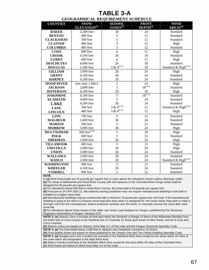
67
TABLE 3-AGEOGRAPHICAL REQUIREMENT SCHEDULE
COUNTIES SNOWELEVATION(1)
SEISMICZONES(2)
FROSTDEPTH(3)
WINDAREAS(4)
BAKERBENTON
CLACKAMASCLATSOP
COLUMBIA
3,200 feet400 feet500 feet400 feet400 feet
2b3333
2412121212
StandardStandardStandard
HighStandard
COOSCROOKCURRY
DESCHUTESDOUGLAS
400 feet4,100 feet400 feet
4,000 feet1,500 feet
42b4
2b3 & 4(2-a)
1218121818
HighStandard
HighStandard
Standard & High(4-a)
GILLIAMGRANT
HARNEY
3,000 feet4,100 feet4,100 feet
2b2b2b
242424
HighStandardStandard
HOOD RIVERJACKSON
JEFFERSON
(see note 1-b&c)2,000 feet4,100 feet
33
2b
2418(3-a)
18
HighStandard
HighJOSEPHINEKLAMATH
LAKELANE
LINCOLN
4,100 feet4,000 feet4,200 feet500 feet400 feet
33
2b3 & 4(2-a)
3 & 4(2-a)
18(3-a)
24241212
StandardStandardStandard
Standard & High(4-a)
High
LINNMALHEURMARION
MORROW
700 feet3,400 feet500 feet
3,000 feet
32b3
2b
12241224
StandardStandardStandard
HighMULTNOMAH
POLKSHERMAN
500 feet(1-b)
400 feet2,000 feet
33
2b
181224
HighStandard
HighTILLAMOOKUMATILLA
UNION
400 feet3,000 feet3,000 feet
32b2b
122424
HighHigh
StandardWALLOWA
WASCO3,000 feet2,000 feet
2b2b
2424
StandardStandard & High(4-b)
WASHINGTONWHEELERYAMHILL
400 feet4,100 feet400 feet
32b3
122412
StandardStandardStandard
NOTE1: (a) Roof snow loads are 25 pounds per square foot or more above the elevations shown unless otherwise noted.(b) For areas in Multnomah and Hood River County with full exposure to the Columbia River Gorge winds shall bedesigned for 28 pounds per square foot.(c) For elevations below 500 feet in Hood River County, the snow load is 50 pounds per square foot(d) Pursuant to 24 CFR 3282.11, the authority having jurisdiction may not require manufactured dwellings to be built orinstalled to a higher snow load.(e) Manufactured dwellings may be constructed with a minimum 20-pound per square foot roof load. If the manufactureddwelling is going to be sited in a heavier snow load area than what it is designed for, the home owner may wish to order astronger roof from the manufacturer, build a protective ramada over the home, or manually remove the snow after eachsnow fall.(f) For elevations above those shown in this table, see Snow Load Analysis for Oregon, published by the StructuralEngineers Association of Oregon, Revised 2/78.NOTE 2: (a) Seismic Zone 4 includes all that land which lies Westerly of Range 10 West of the Willamette Meridian fromthe North side of Coos County to the Northerly line of Township 10 South (just South of Otter Rock), and all of Coos andCurry Counties.(b) Seismic zones are based on Seismic Zone Map 3-C of this code and the Oregon Structural Specialty Code.NOTE 3: (a) The frost depth below 2,500 feet in Jackson and Josephine Counties is 12 inches.(b) Frost depths shown are based on those published in the Oregon One and Two Family Dwelling Specialty Code.NOTE 4: (a) Douglas and Lane Counties are primarily in the Standard Wind Area except for the areas within 20 miles ofthe coast which are designated in the High Wind Area.(b) Wasco County is primarily in the Standard Wind Area except for the area within 30 miles of the Columbia River.(c) Wind Areas are based on Wind Area Map 3-A of this code.
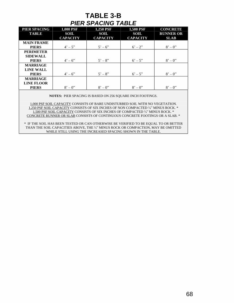
68
TABLE 3-BPIER SPACING TABLE
PIER SPACINGTABLE
1,000 PSFSOIL
CAPACITY
1,250 PSFSOIL
CAPACITY
1,500 PSFSOIL
CAPACITY
CONCRETERUNNER OR
SLABMAIN FRAME
PIERS 4’ – 5” 5’ – 6” 6’ – 2” 8’ – 0”PERIMETERSIDEWALL
PIERS 4’ – 6” 5’ – 8” 6’ – 5” 8’ – 0”MARRIAGELINE WALL
PIERS 4’ – 6” 5’ – 8” 6’ – 5” 8’ – 0”MARRIAGE
LINE FLOORPIERS 8’ – 0” 8’ – 0” 8’ – 0” 8’ – 0”
NOTES: PIER SPACING IS BASED ON 256 SQUARE INCH FOOTINGS.
1,000 PSF SOIL CAPACITY CONSISTS OF BARE UNDISTURBED SOIL WITH NO VEGETATION.1,250 PSF SOIL CAPACITY CONSISTS OF SIX INCHES OF NON COMPACTED ¾ ” MINUS ROCK. *
1,500 PSF SOIL CAPACITY CONSISTS OF SIX INCHES OF COMPACTED ¾ ” MINUS ROCK. *CONCRETE RUNNER OR SLAB CONSISTS OF CONTINUOUS CONCRETE FOOTINGS OR A SLAB. *
* IF THE SOIL HAS BEEN TESTED OR CAN OTHERWISE BE VERIFIED TO BE EQUAL TO OR BETTERTHAN THE SOIL CAPACITIES ABOVE, THE ¾ ” MINUS ROCK OR COMPACTION, MAY BE OMITTED
WHILE STILL USING THE INCREASED SPACING SHOWN IN THE TABLE.
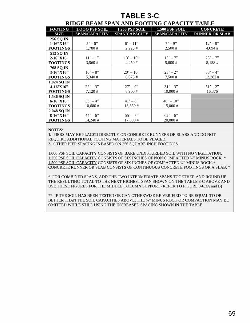
69
TABLE 3-CRIDGE BEAM SPAN AND FOOTING CAPACITY TABLE
FOOTINGSIZE
1,OOO PSF SOILSPAN/CAPACITY
1,250 PSF SOILSPAN/CAPACITY
1,500 PSF SOILSPAN/CAPACITY
CONCRETERUNNER OR SLAB
256 SQ IN1-16” X16”
FOOTINGS5’ – 6”1,780 #
6’ – 11”2,225 #
7’ – 9”2,500 #
12’ – 9”4,094 #
512 SQ IN2-16” X16”
FOOTINGS11’ – 1”3,560 #
13’ – 10”4,450 #
15’ – 7”5,000 #
25’ – 7”8,188 #
768 SQ IN3-16” X16”
FOOTINGS16’ – 8”5,340 #
20’ – 10”6,675 #
23’ – 2”7,500 #
38’ – 4”12,282 #
1,024 SQ IN4-16’X16”
FOOTINGS22’ – 3”7,120 #
27’ – 9”8,900 #
31’ – 3”10,000 #
51’ – 2”16,376
1,536 SQ IN6-16” X16”
FOOTINGS33’ – 4”10,680 #
41’ – 8”13,350 #
46’ – 10”15,000 #
2,048 SQ IN8-16” X16”
FOOTINGS44’ – 6”14,240 #
55’ – 7”17,800 #
62’ – 6”20,000 #
NOTES:1. PIERS MAY BE PLACED DIRECTLY ON CONCRETE RUNNERS OR SLABS AND DO NOTREQUIRE ADDITIONAL FOOTING MATERIALS TO BE PLACED.2. OTHER PIER SPACING IS BASED ON 256 SQUARE INCH FOOTINGS.
1,000 PSF SOIL CAPACITY CONSISTS OF BARE UNDISTURBED SOIL WITH NO VEGETATION.1,250 PSF SOIL CAPACITY CONSISTS OF SIX INCHES OF NON COMPACTED ¾ ” MINUS ROCK. *1,500 PSF SOIL CAPACITY CONSISTS OF SIX INCHES OF COMPACTED ¾ ” MINUS ROCK.*CONCRETE RUNNER OR SLAB CONSISTS OF CONTINUOUS CONCRETE FOOTINGS OR A SLAB. *
* FOR COMBINED SPANS, ADD THE TWO INTERMEDIATE SPANS TOGETHER AND ROUND UPTHE RESULTING TOTAL TO THE NEXT HIGHEST SPAN SHOWN ON THE TABLE 3-C ABOVE ANDUSE THESE FIGURES FOR THE MIDDLE COLUMN SUPPORT (REFER TO FIGURE 3-6.3A and B)
** IF THE SOIL HAS BEEN TESTED OR CAN OTHERWISE BE VERIFIED TO BE EQUAL TO ORBETTER THAN THE SOIL CAPACITIES ABOVE, THE ¾ ” MINUS ROCK OR COMPACTION MAY BEOMITTED WHILE STILL USING THE INCREASED SPACING SHOWN IN THE TABLE.
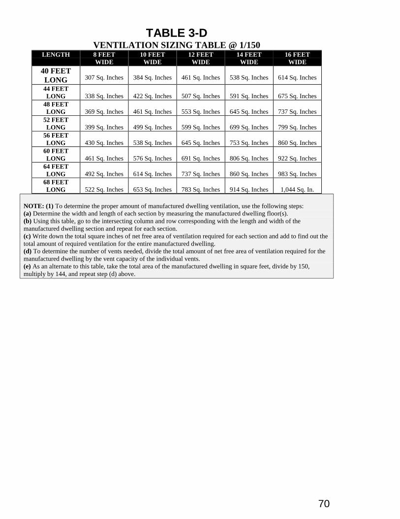
70
TABLE 3-DVENTILATION SIZING TABLE @ 1/150
LENGTH 8 FEETWIDE
10 FEETWIDE
12 FEETWIDE
14 FEETWIDE
16 FEETWIDE
40 FEETLONG 307 Sq. Inches 384 Sq. Inches 461 Sq. Inches 538 Sq. Inches 614 Sq. Inches
44 FEETLONG 338 Sq. Inches 422 Sq. Inches 507 Sq. Inches 591 Sq. Inches 675 Sq. Inches
48 FEETLONG 369 Sq. Inches 461 Sq. Inches 553 Sq. Inches 645 Sq. Inches 737 Sq. Inches
52 FEETLONG 399 Sq. Inches 499 Sq. Inches 599 Sq. Inches 699 Sq. Inches 799 Sq. Inches
56 FEETLONG 430 Sq. Inches 538 Sq. Inches 645 Sq. Inches 753 Sq. Inches 860 Sq. Inches
60 FEETLONG 461 Sq. Inches 576 Sq. Inches 691 Sq. Inches 806 Sq. Inches 922 Sq. Inches
64 FEETLONG 492 Sq. Inches 614 Sq. Inches 737 Sq. Inches 860 Sq. Inches 983 Sq. Inches
68 FEETLONG 522 Sq. Inches 653 Sq. Inches 783 Sq. Inches 914 Sq. Inches 1,044 Sq. In.
NOTE: (1) To determine the proper amount of manufactured dwelling ventilation, use the following steps:(a) Determine the width and length of each section by measuring the manufactured dwelling floor(s).(b) Using this table, go to the intersecting column and row corresponding with the length and width of themanufactured dwelling section and repeat for each section.(c) Write down the total square inches of net free area of ventilation required for each section and add to find out thetotal amount of required ventilation for the entire manufactured dwelling.(d) To determine the number of vents needed, divide the total amount of net free area of ventilation required for themanufactured dwelling by the vent capacity of the individual vents.(e) As an alternate to this table, take the total area of the manufactured dwelling in square feet, divide by 150,multiply by 144, and repeat step (d) above.
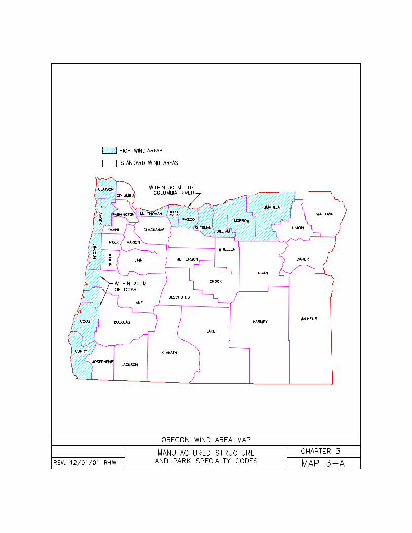
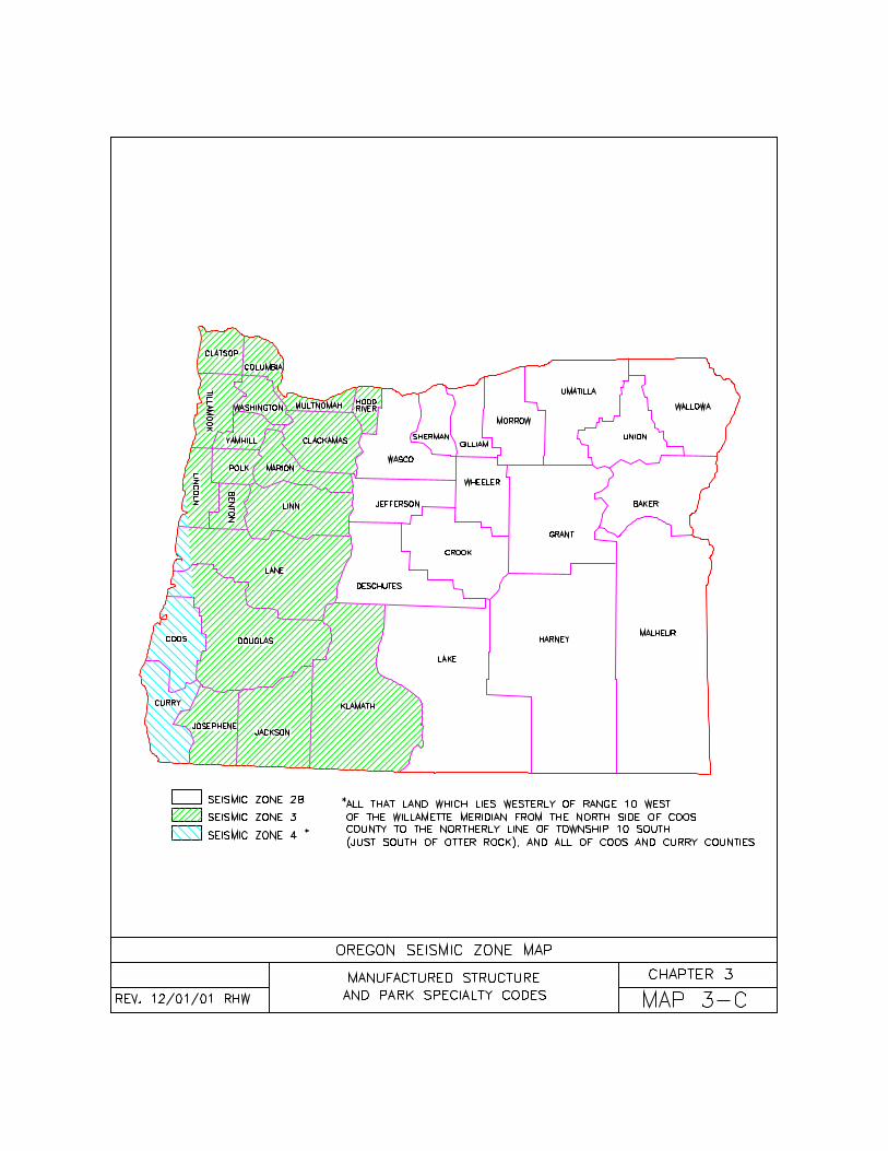
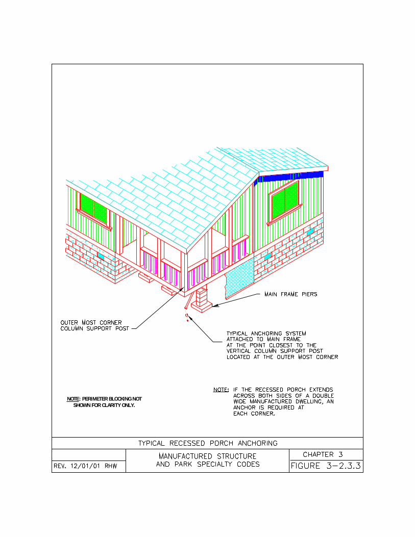
NOTE: PERIMETER BLOCKING NOT SHOWN FOR CLARITY ONLY.
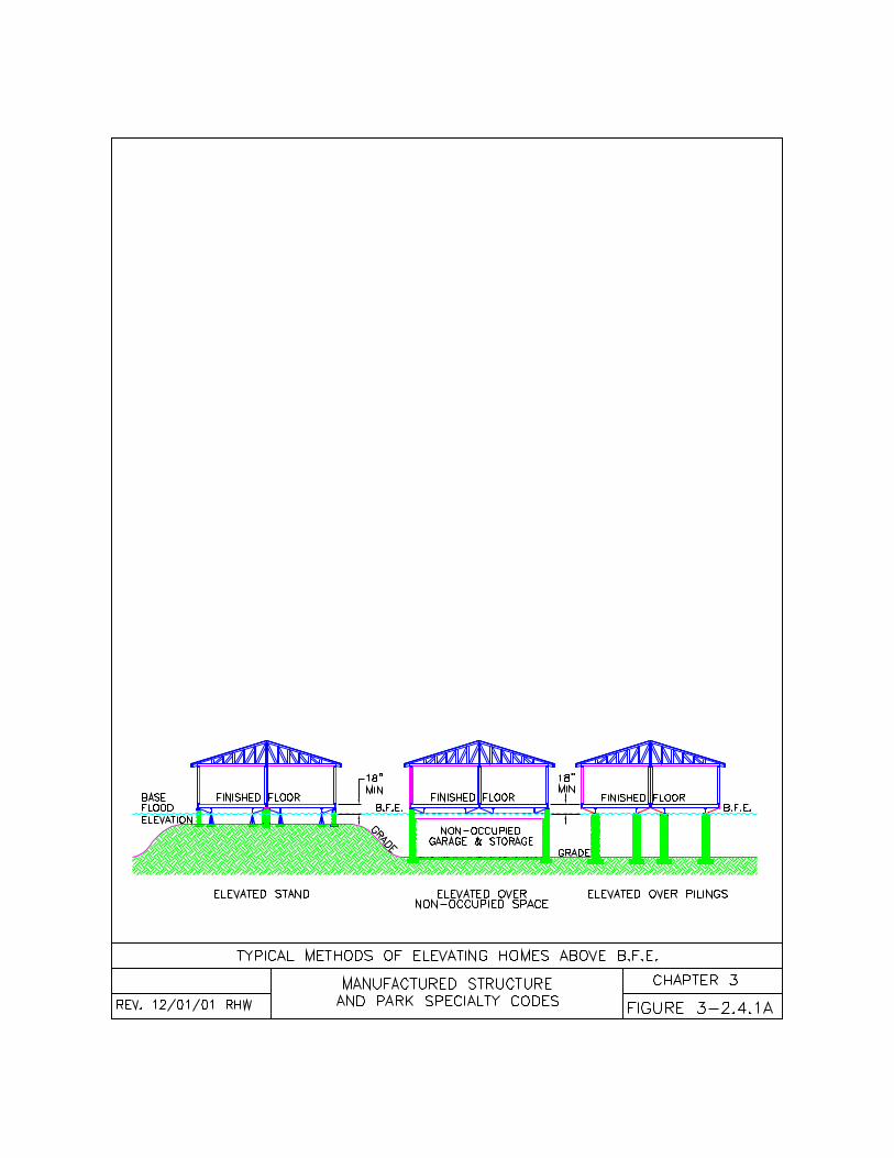
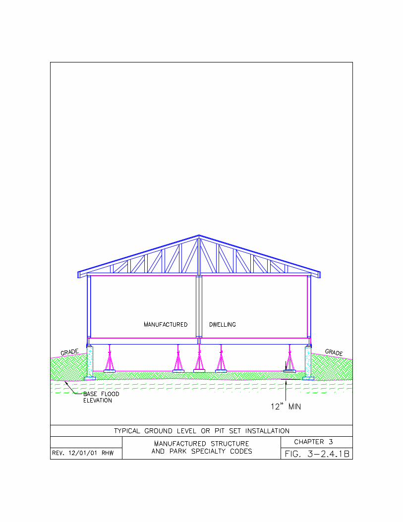
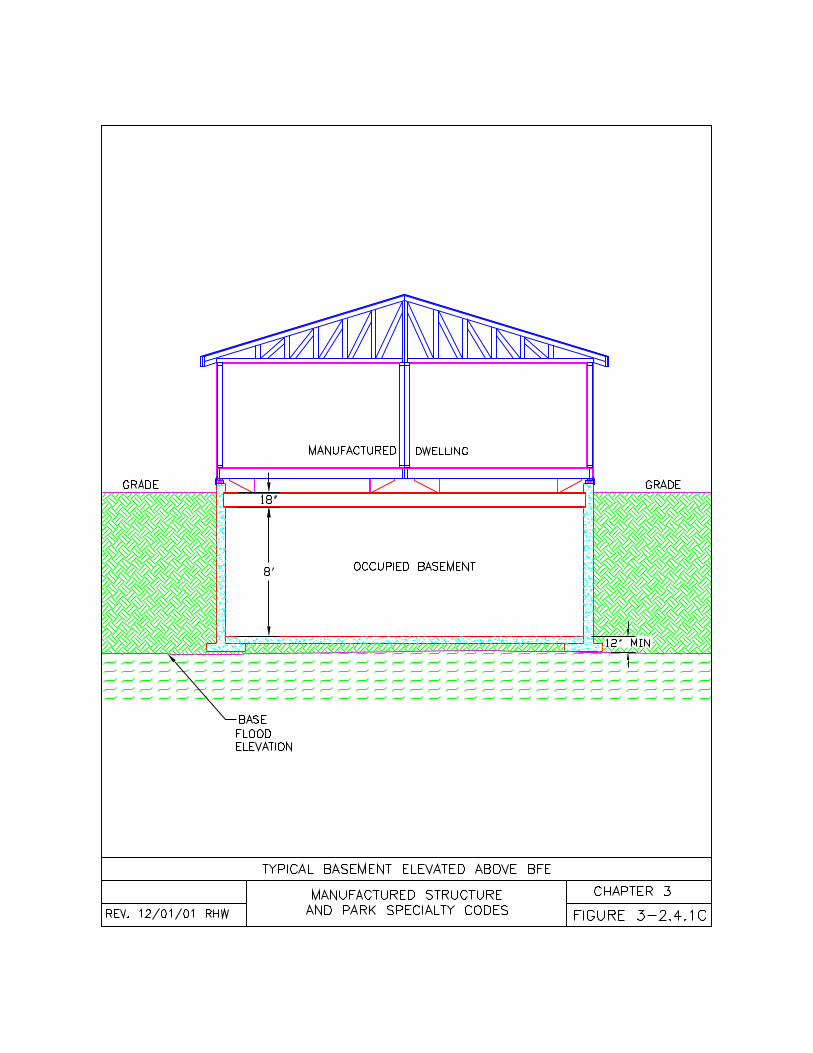
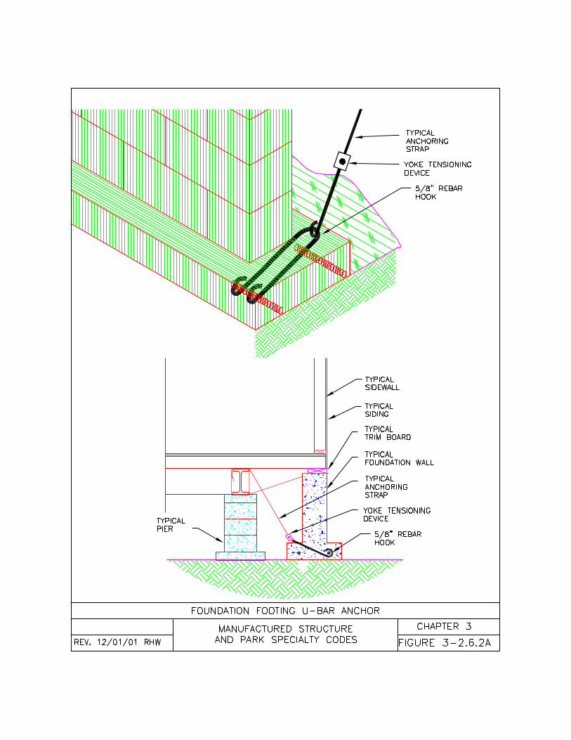
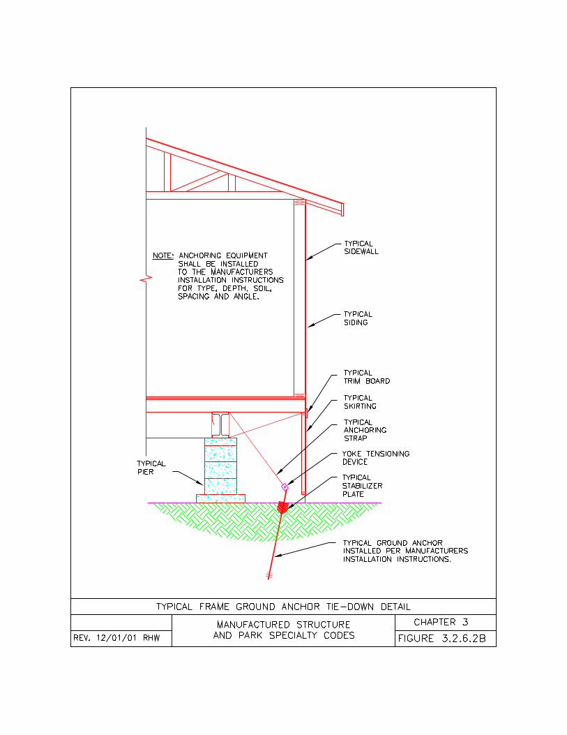
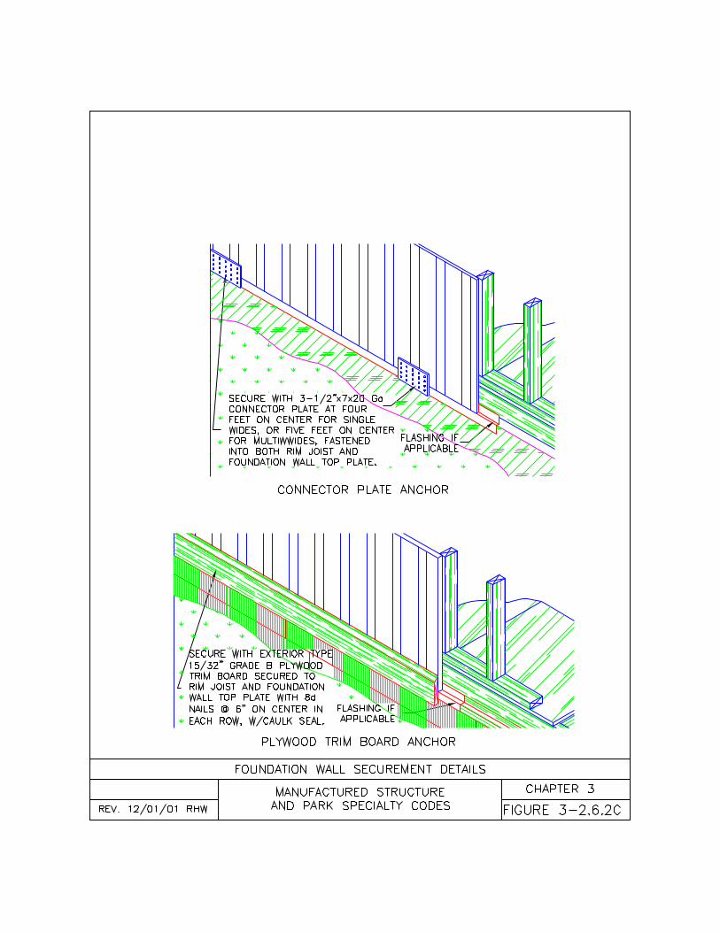
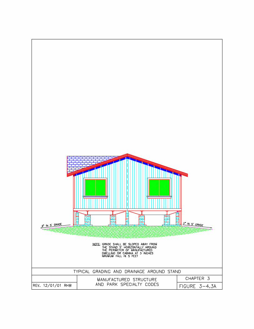
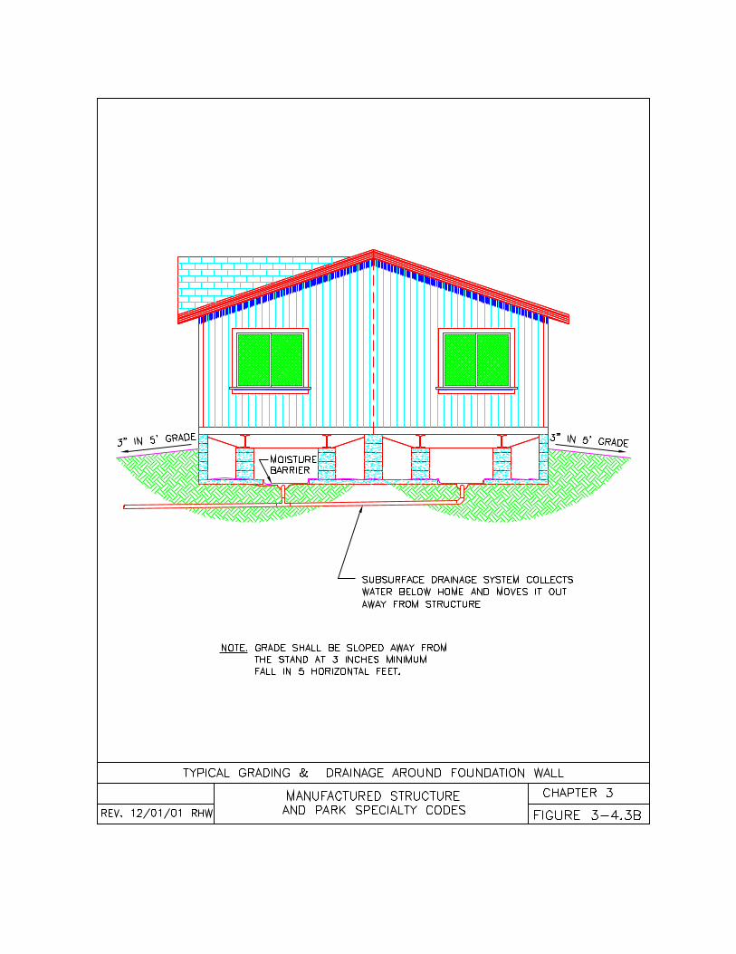
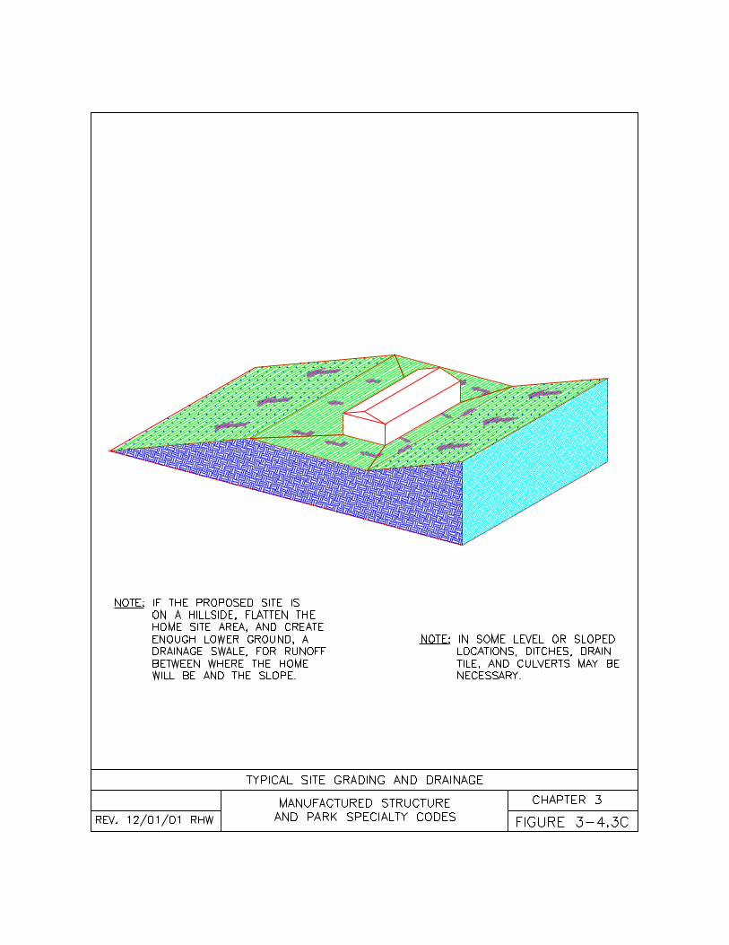
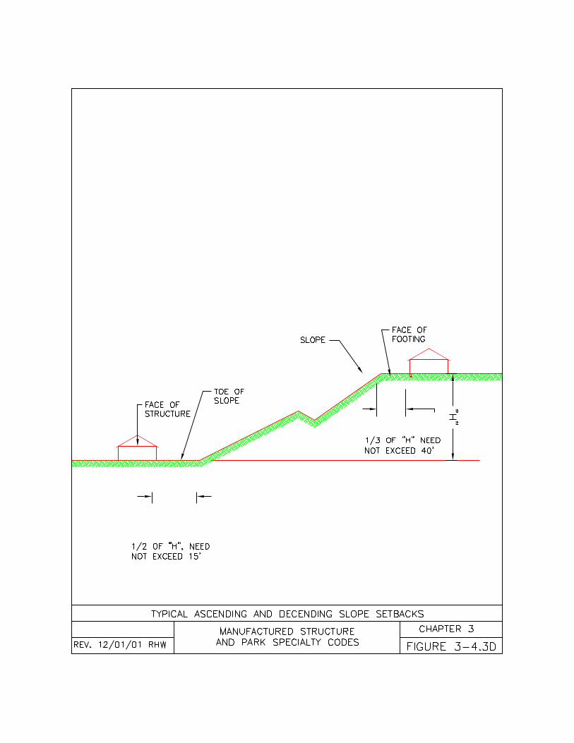
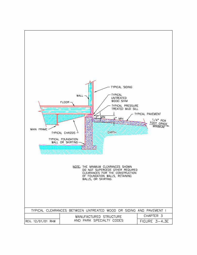
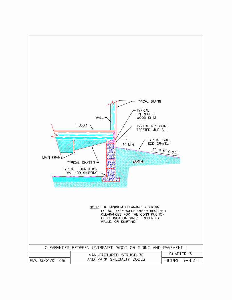
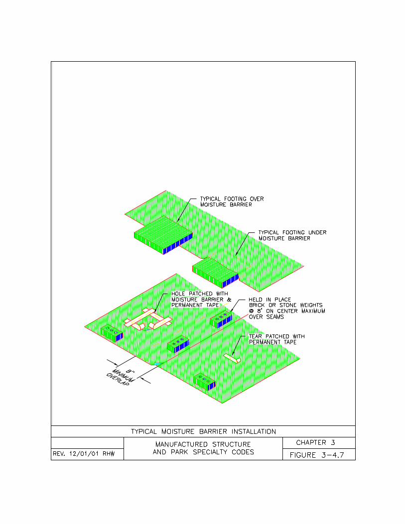
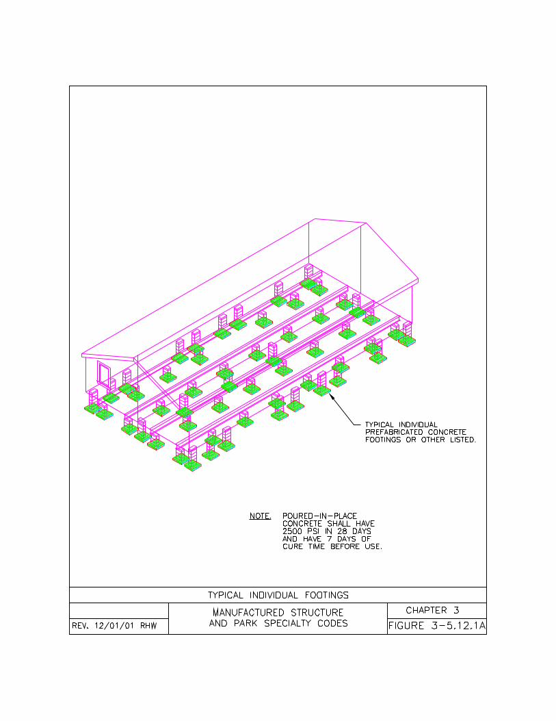
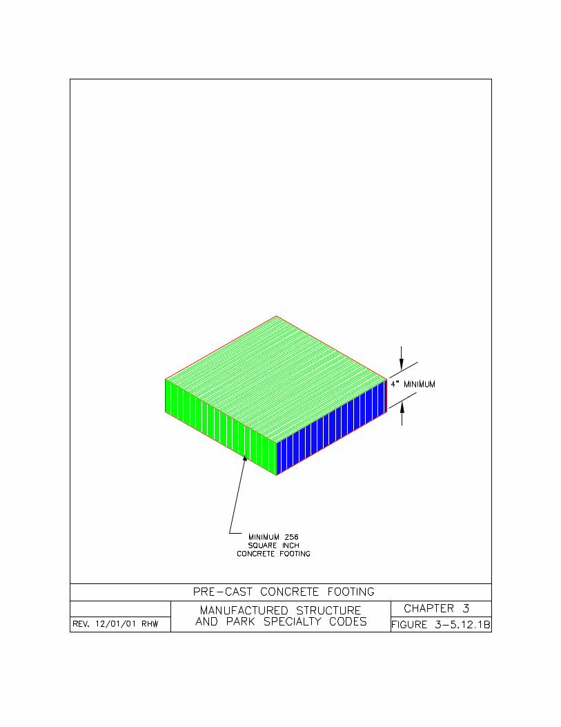
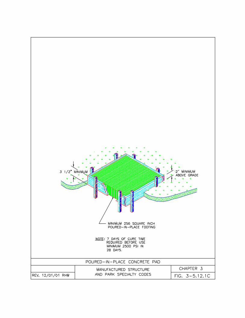
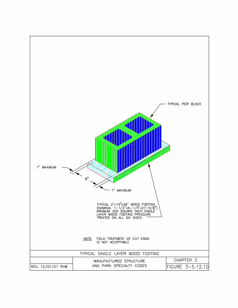
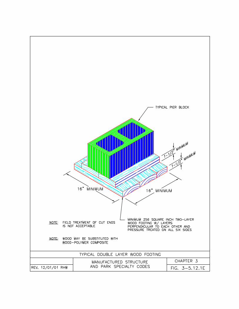
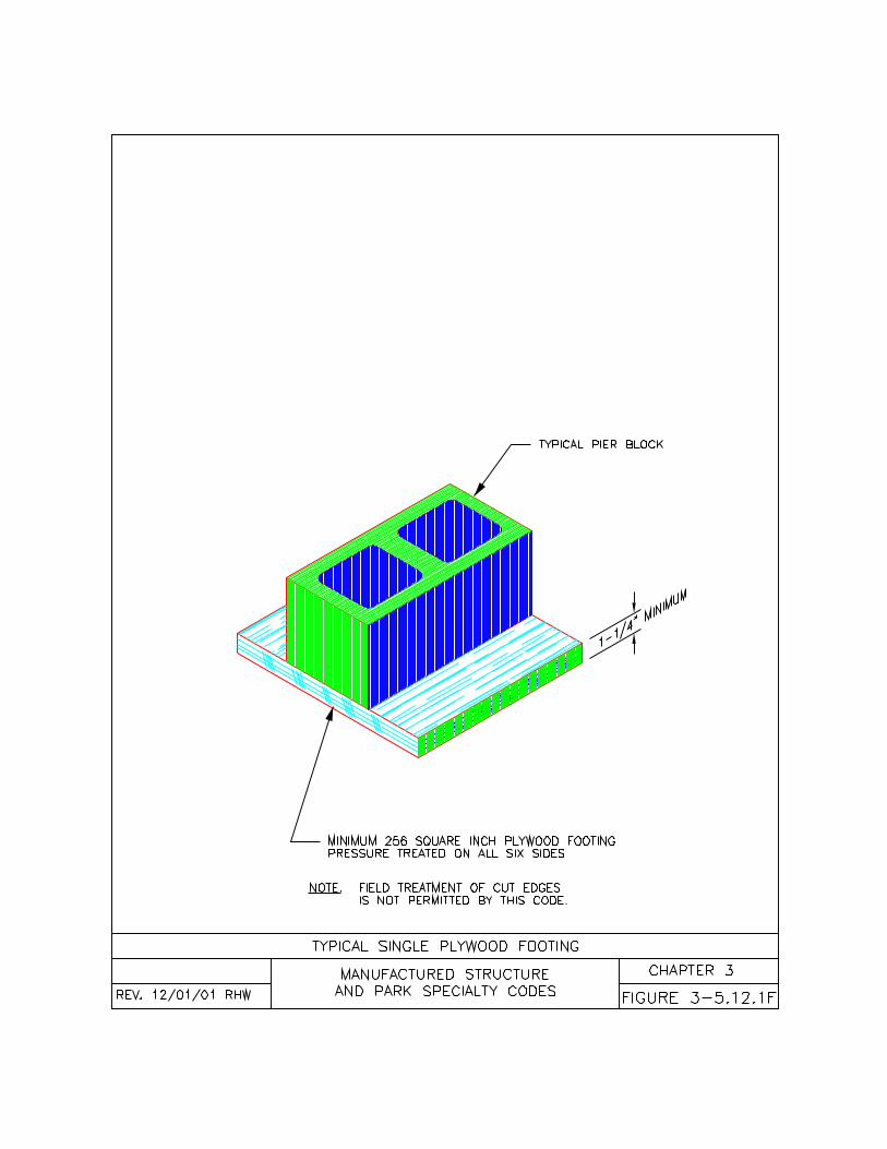
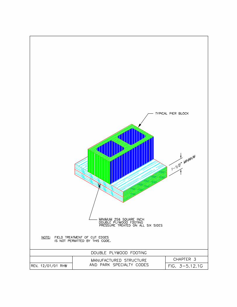
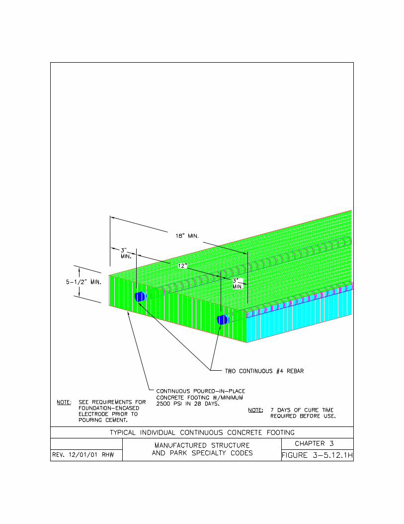
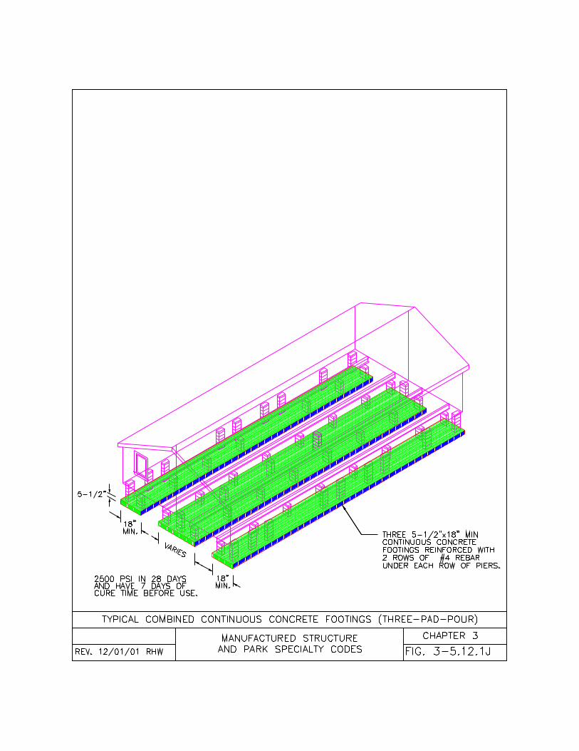
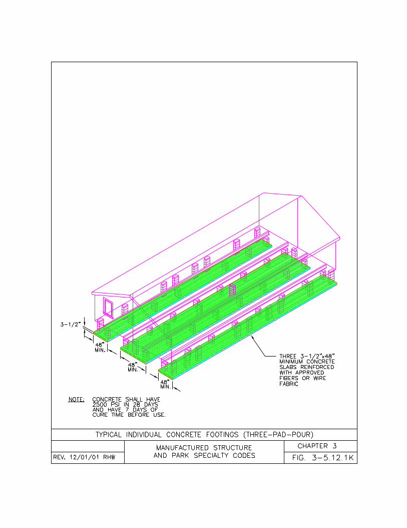
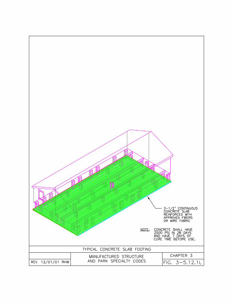
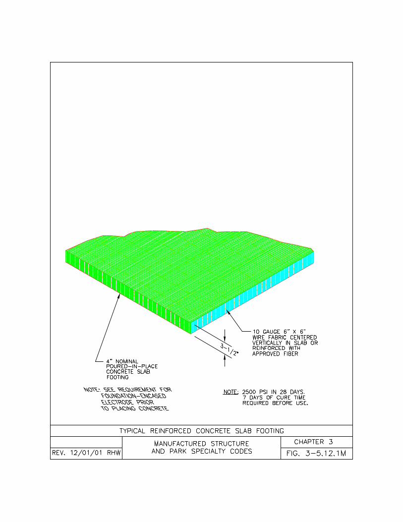
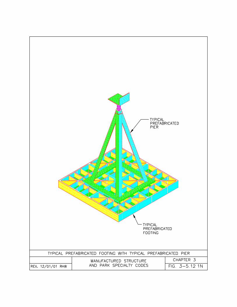
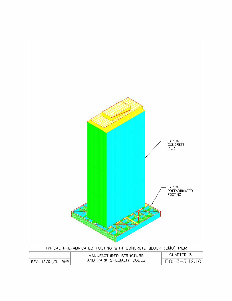
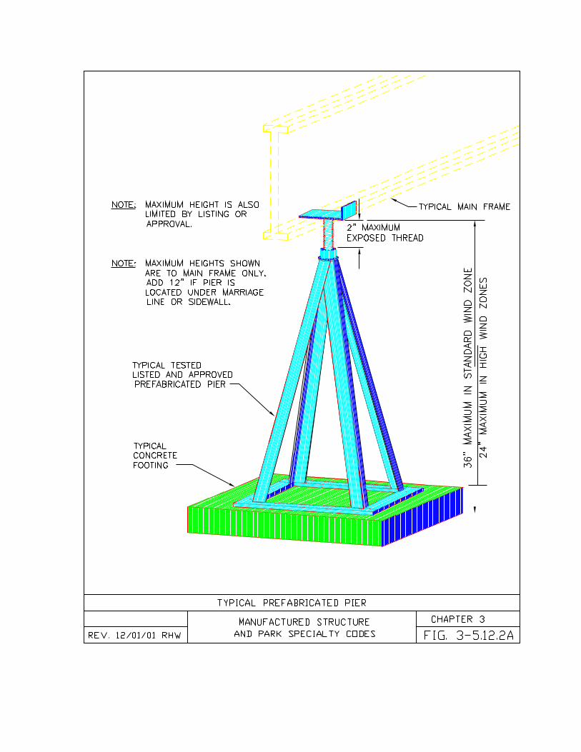
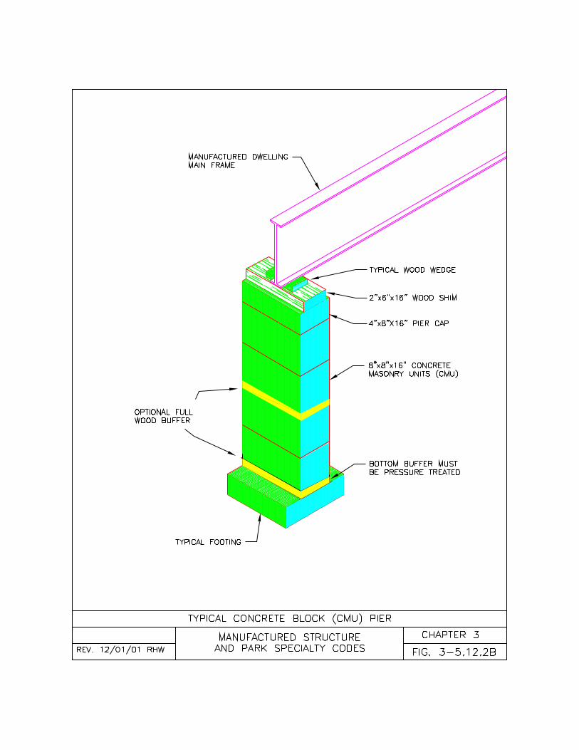
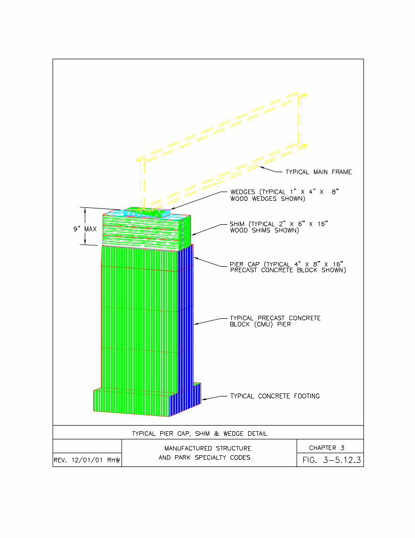
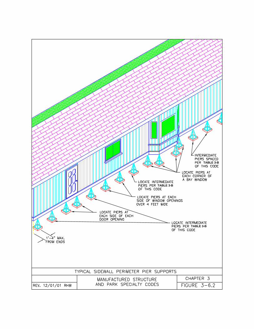
TABLE 3-B
TABLE 3-B
TABLE 3-B
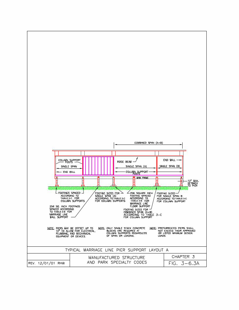
TABLE 3-C
TABLE 3-B
TABLE 3-CTABLE 3-B
TABLE 3-C
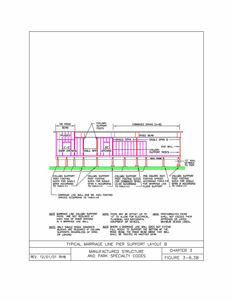
TABLE 3-C TABLE 3-C TABLE 3-C TABLE 3-C
TABLE 3-B
TABLE 3-B
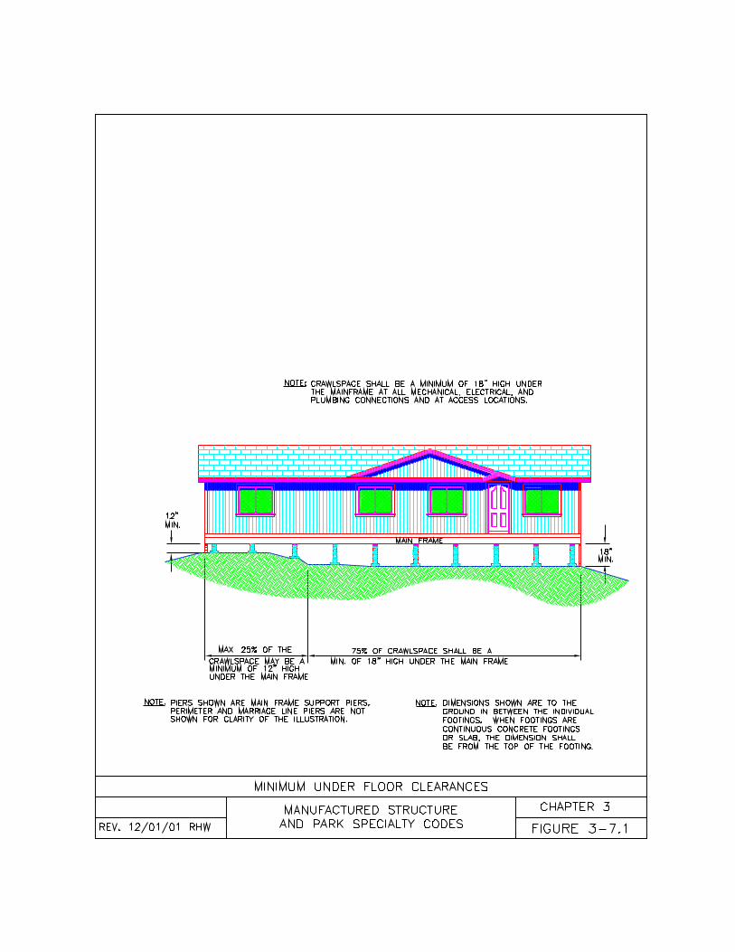
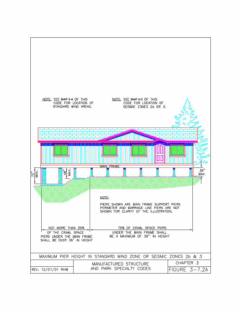
MAP 3-A MAP 3-C
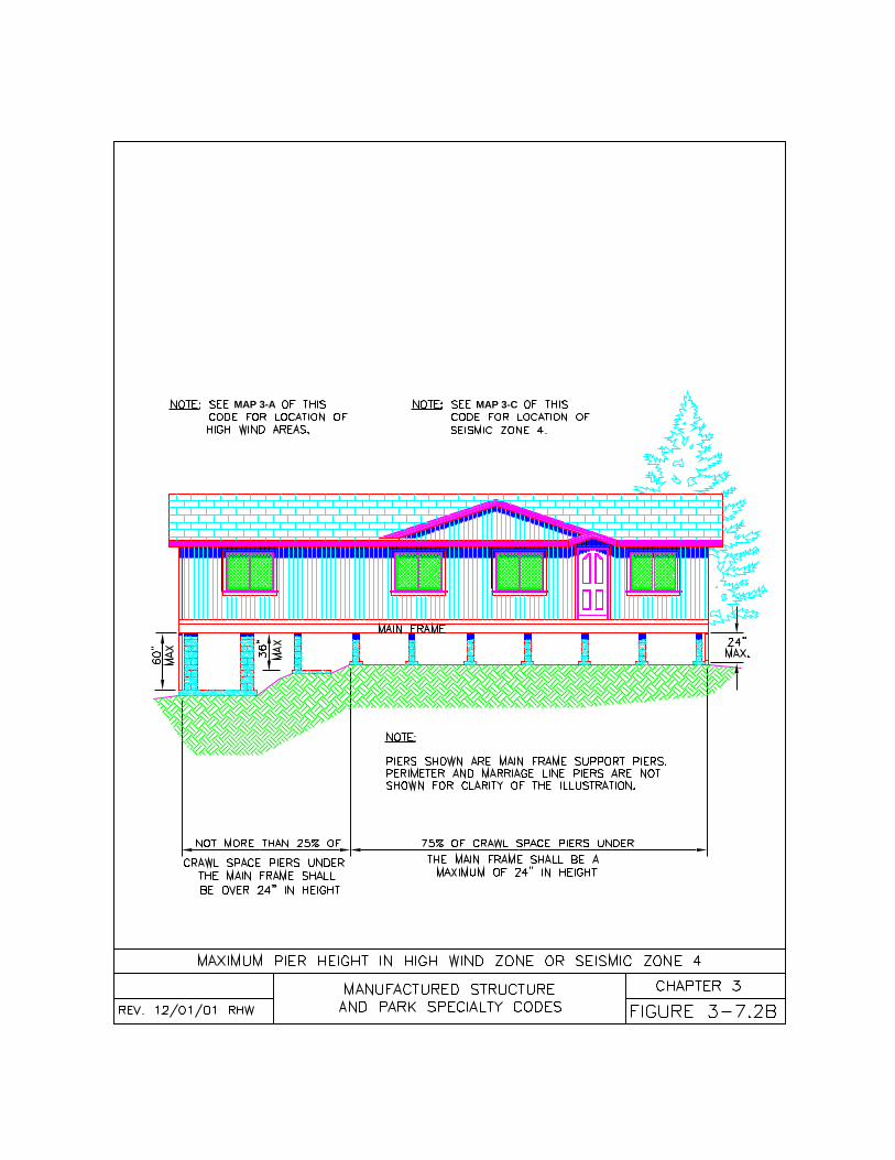
MAP 3-CMAP 3-A
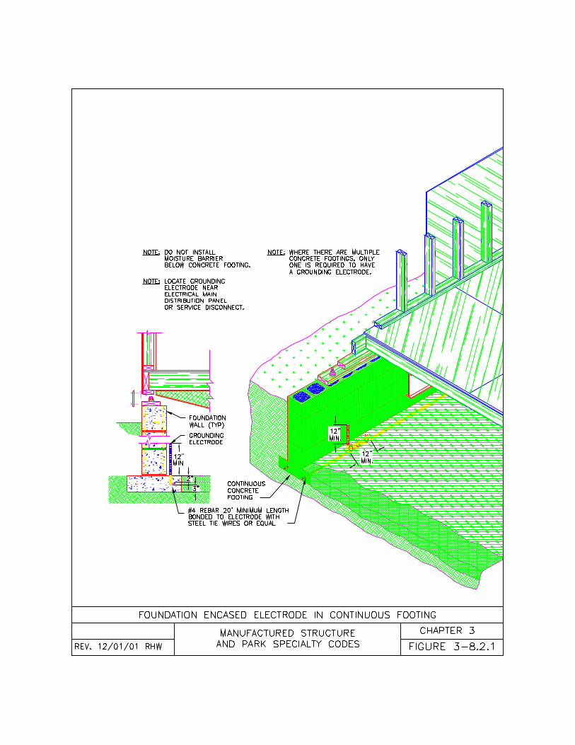
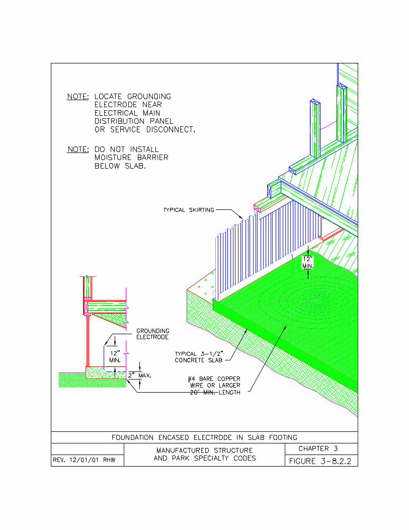
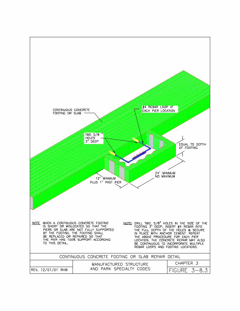
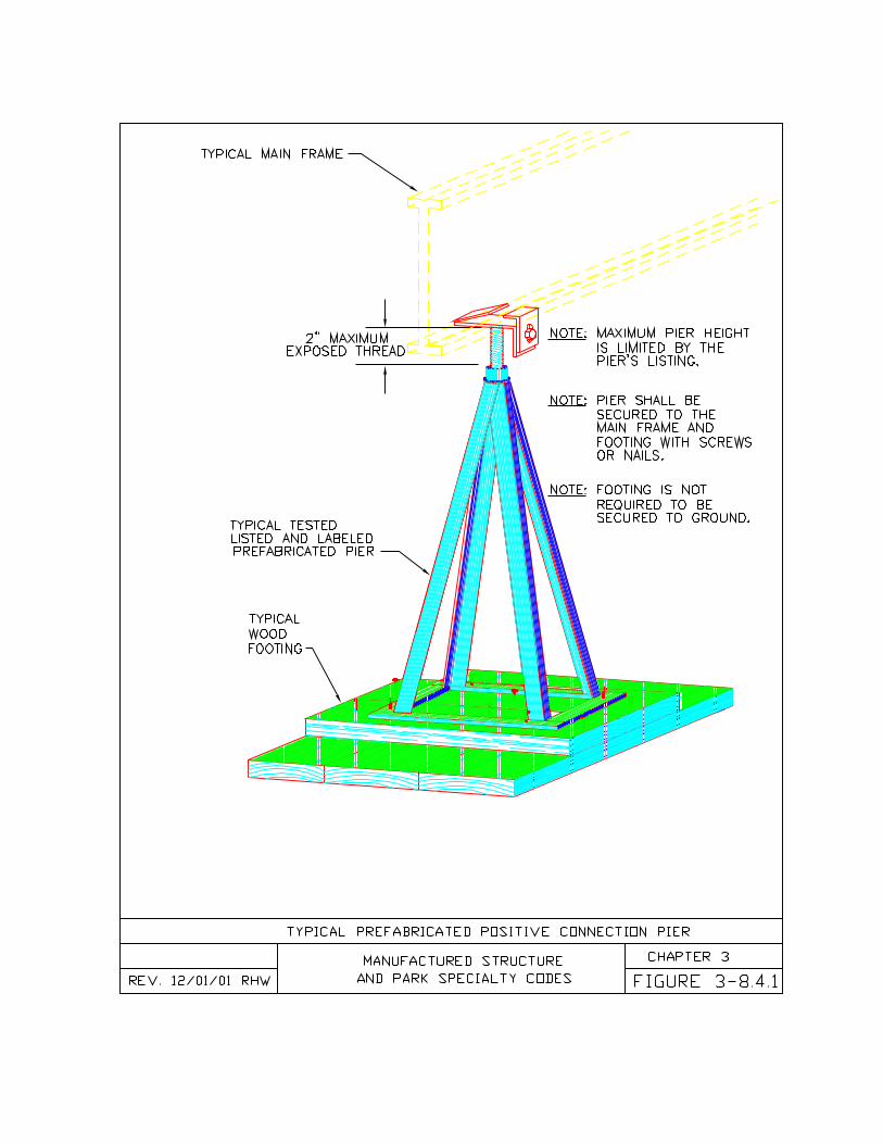
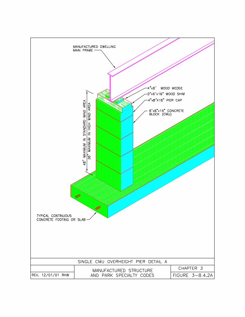
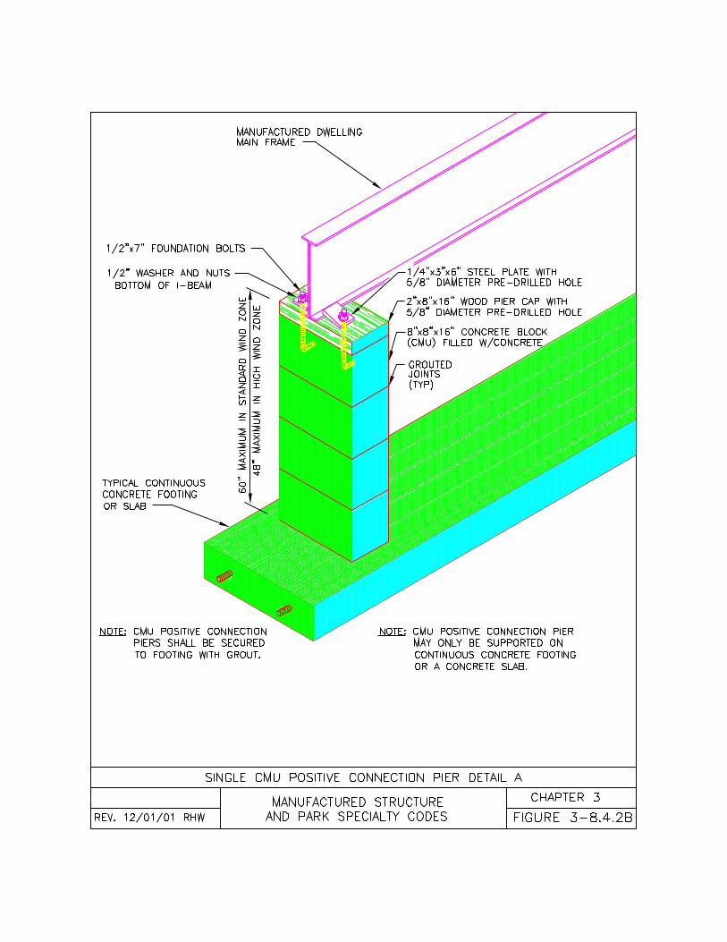
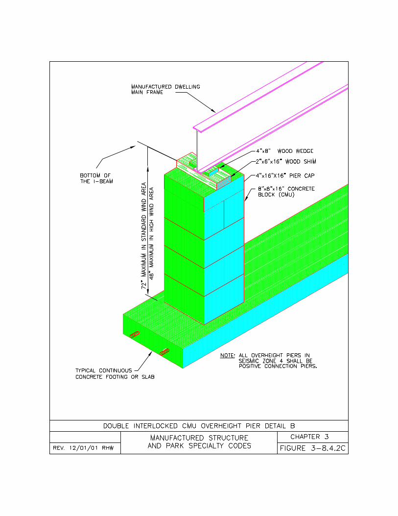
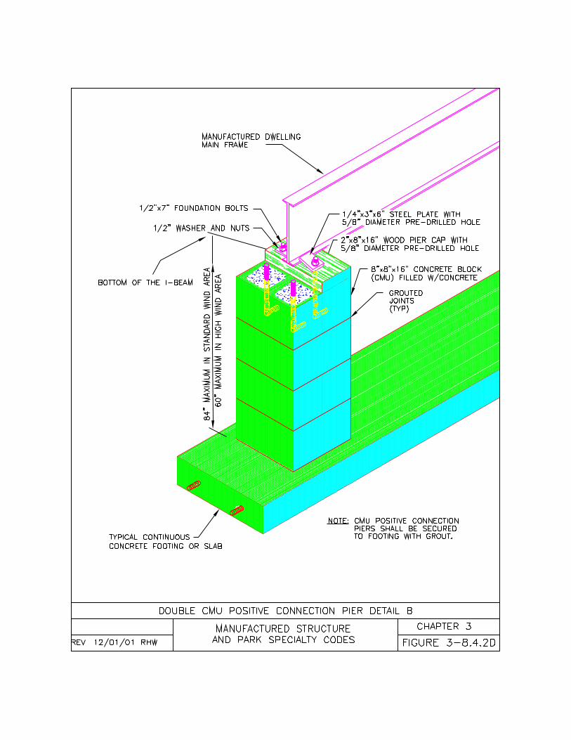
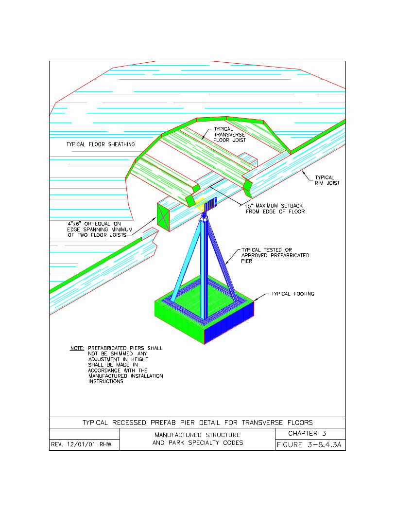
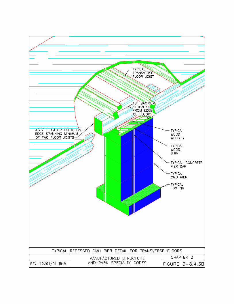
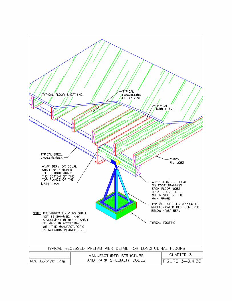
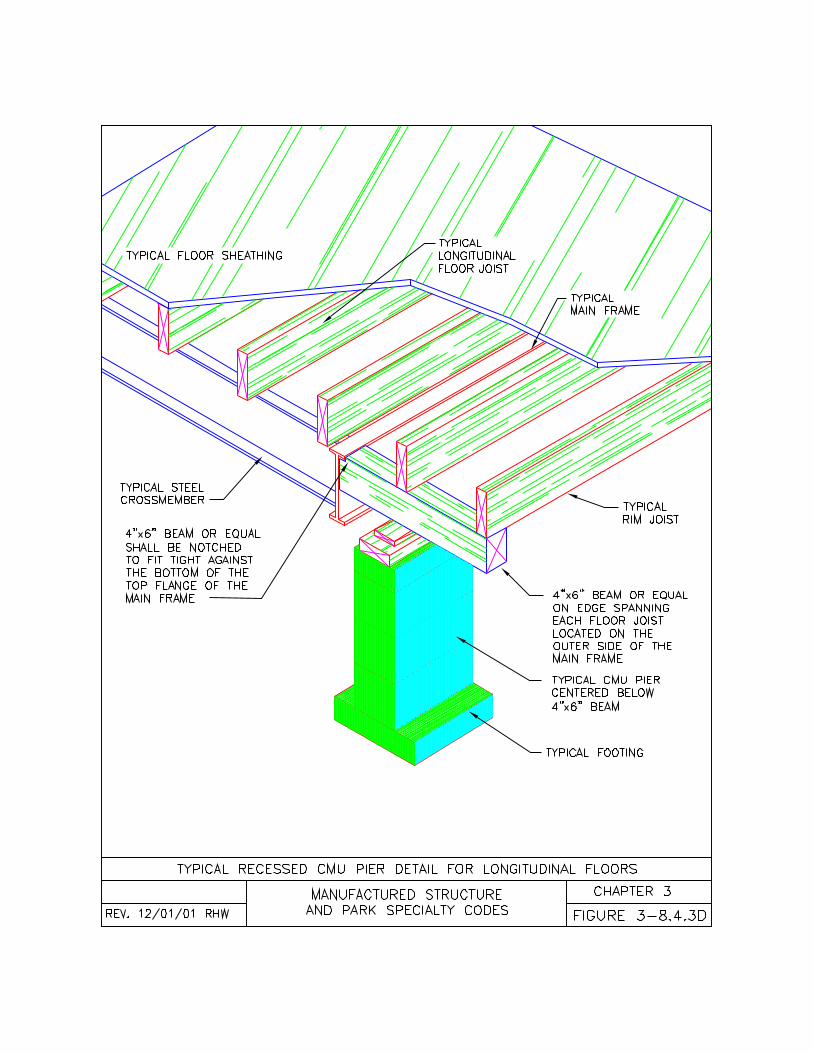
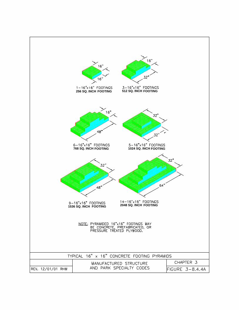
1536 SQ. INCH FOOTING
256 SQ. INCH 512 SQ. INCHFOOTING FOOTING
FOOTING2048 SQ. INCH
1024 SQ. INCH FOOTING768 SQ. INCH FOOTING
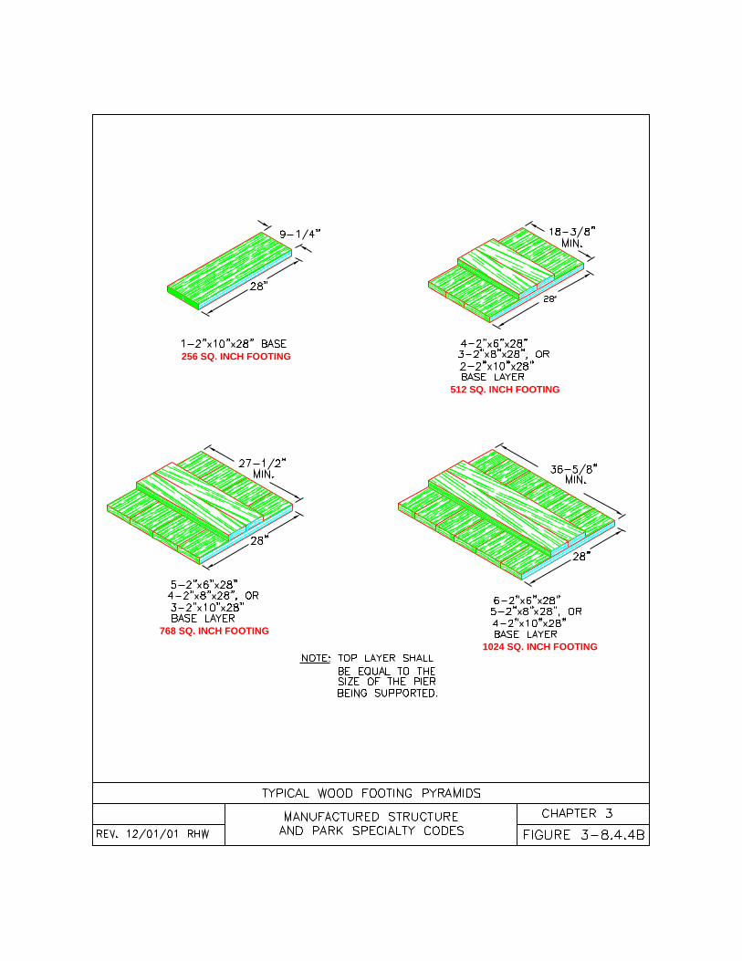
256 SQ. INCH FOOTING
512 SQ. INCH FOOTING
768 SQ. INCH FOOTING
1024 SQ. INCH FOOTING
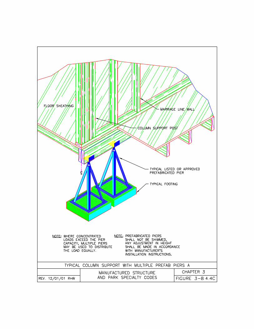
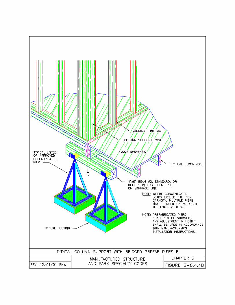
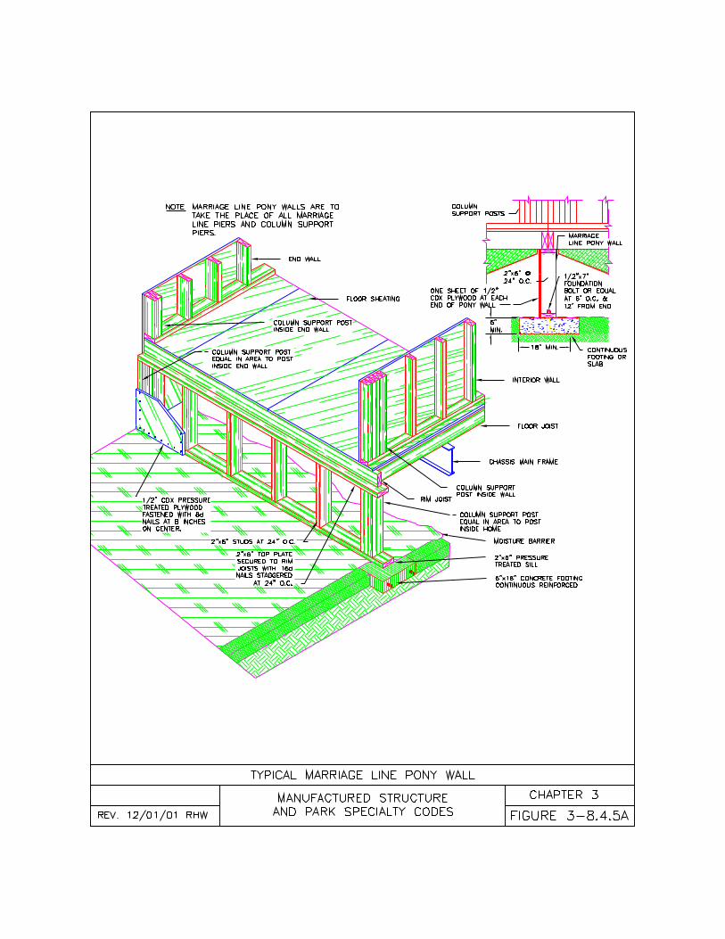
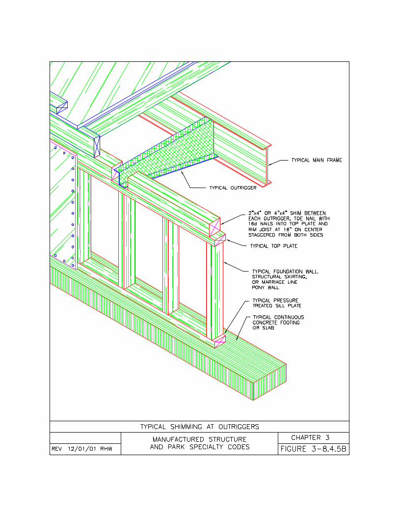
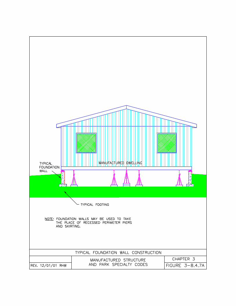
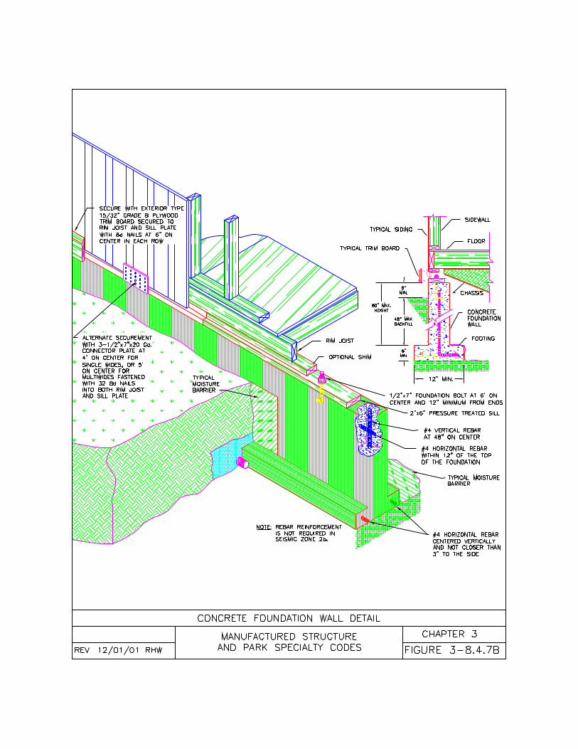
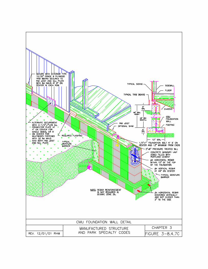
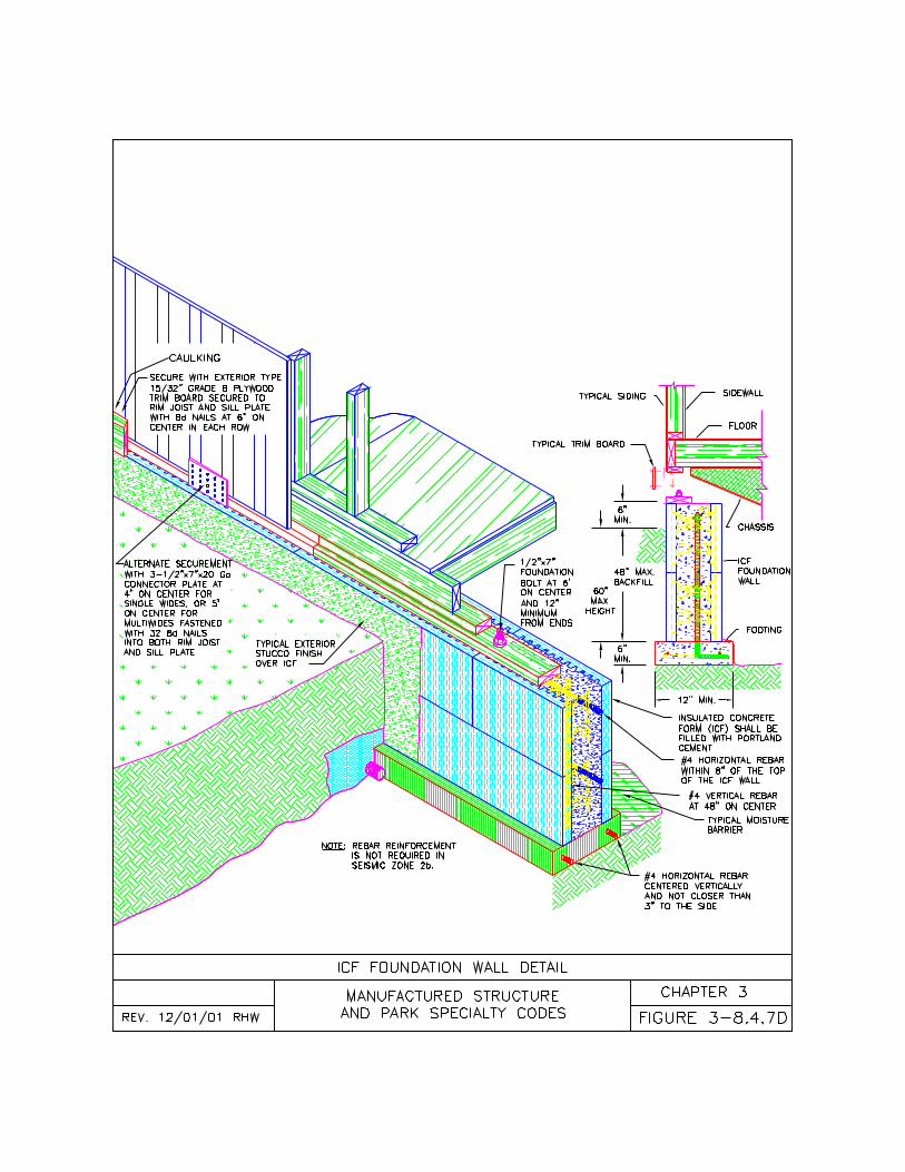
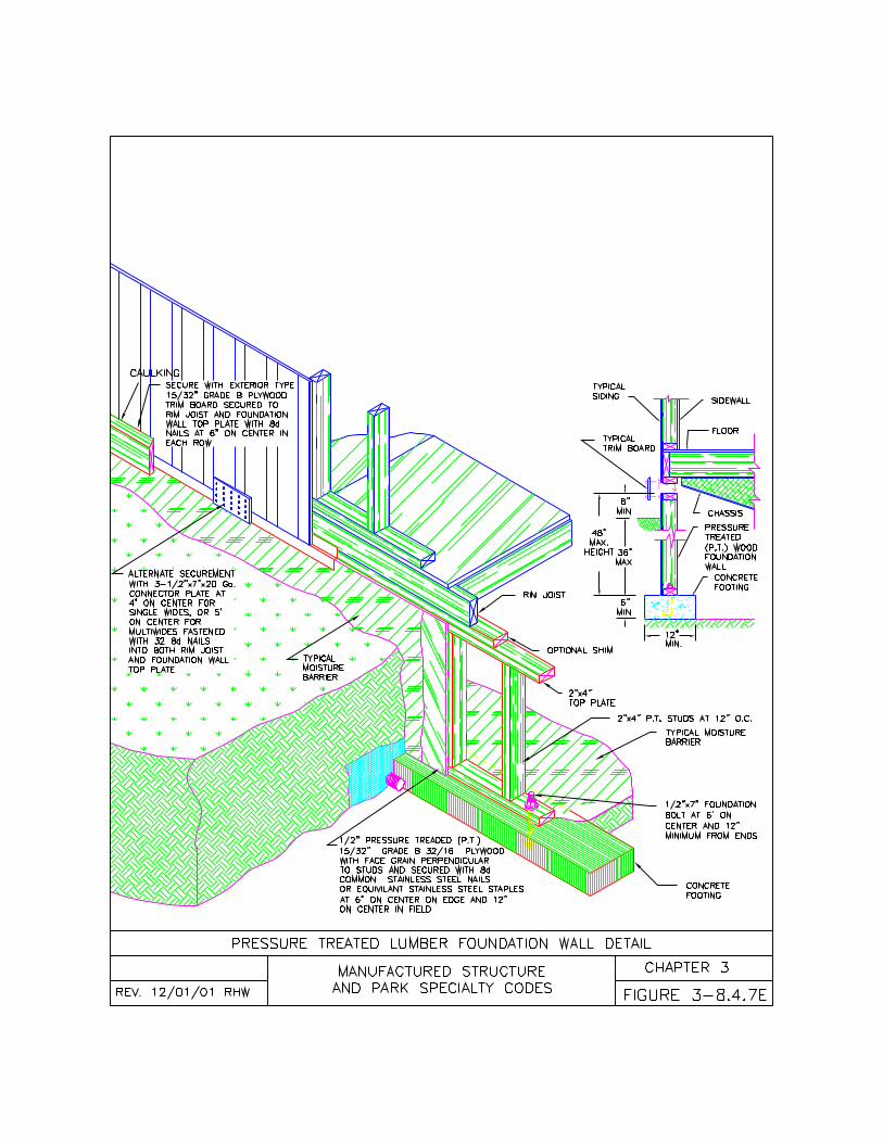
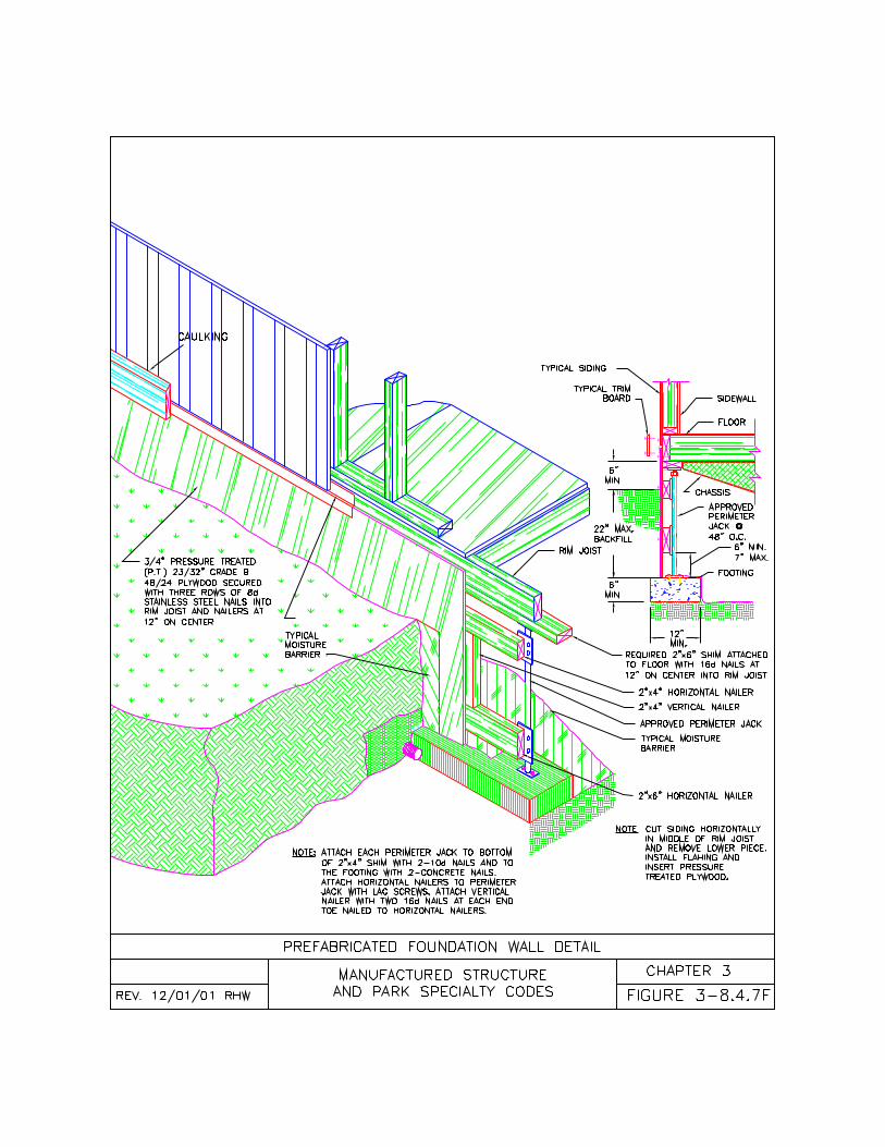
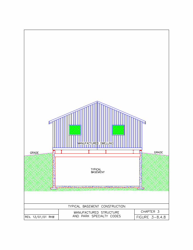
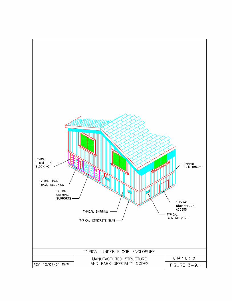
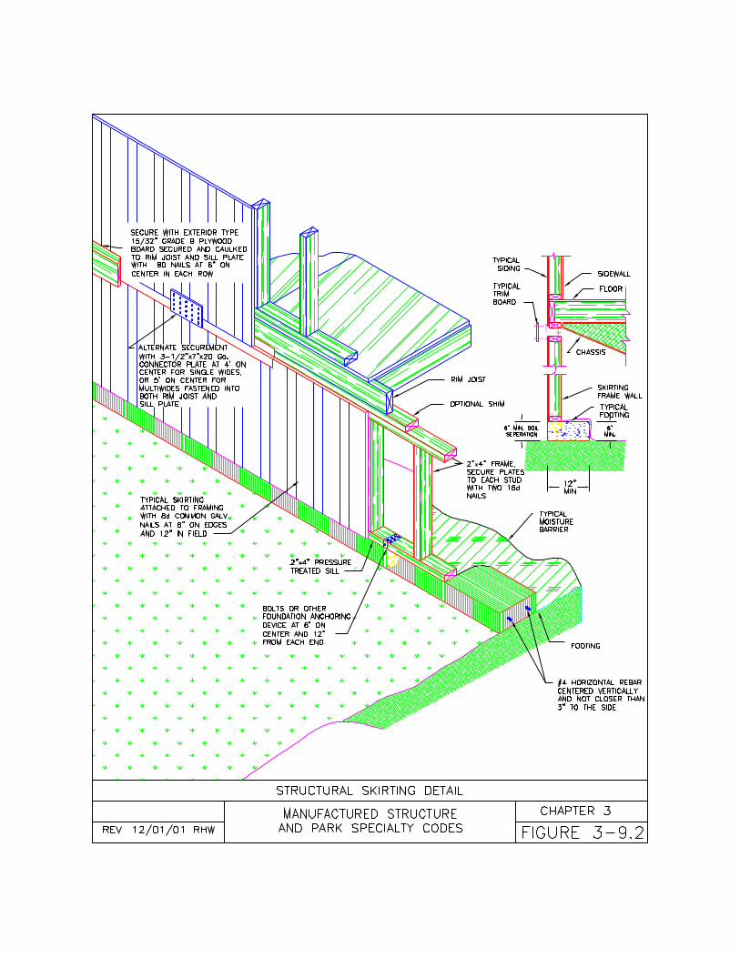
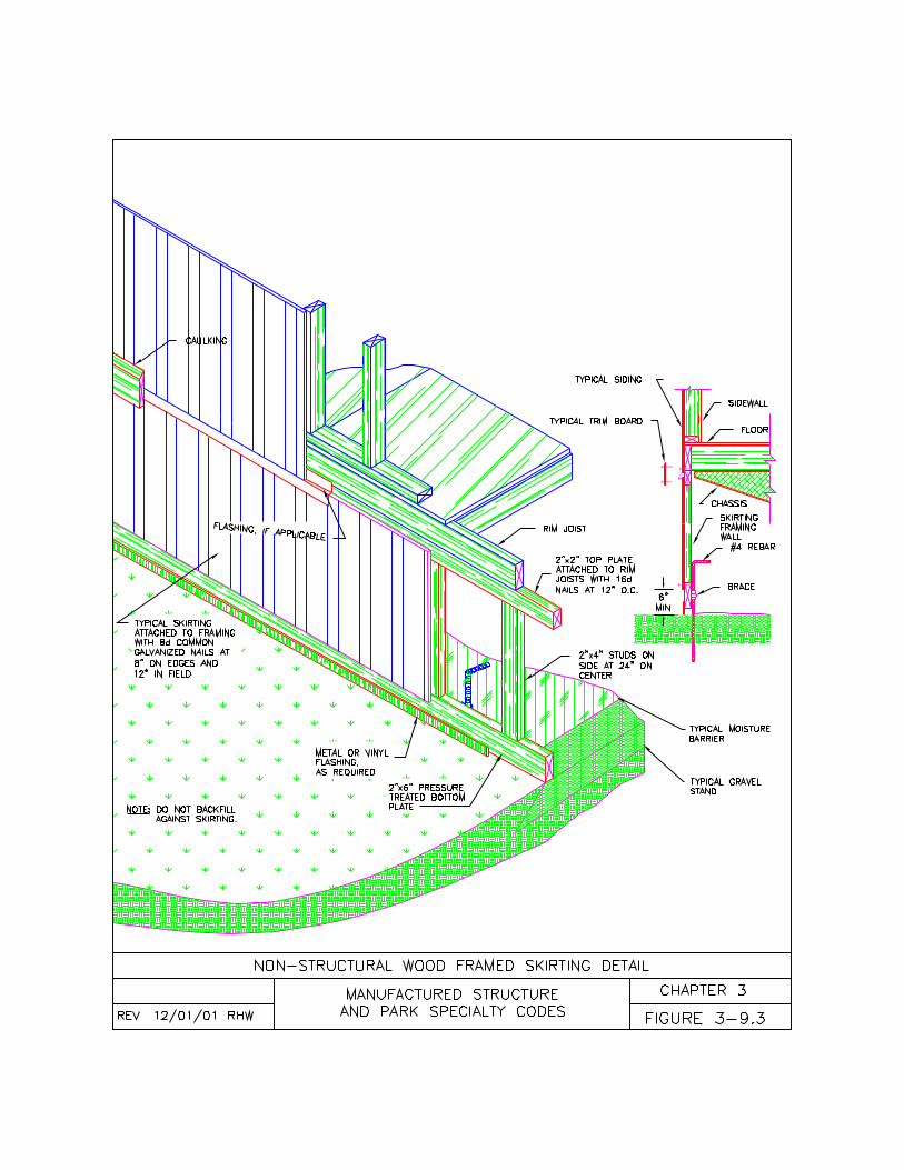
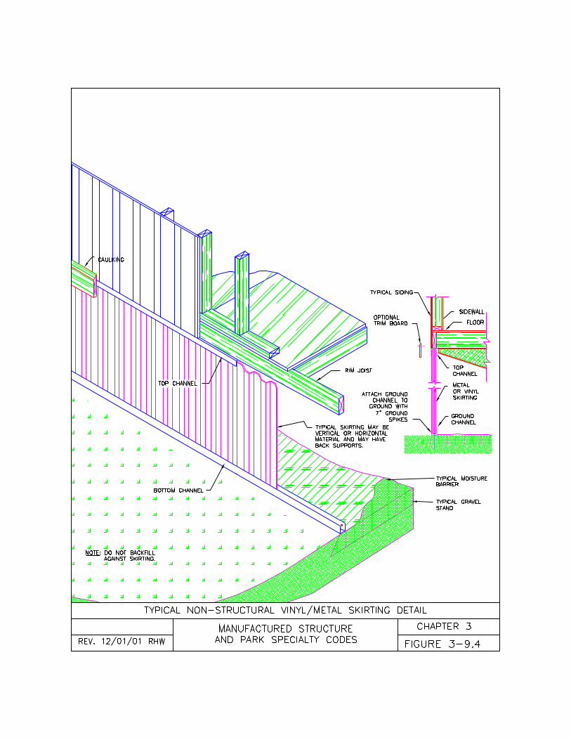
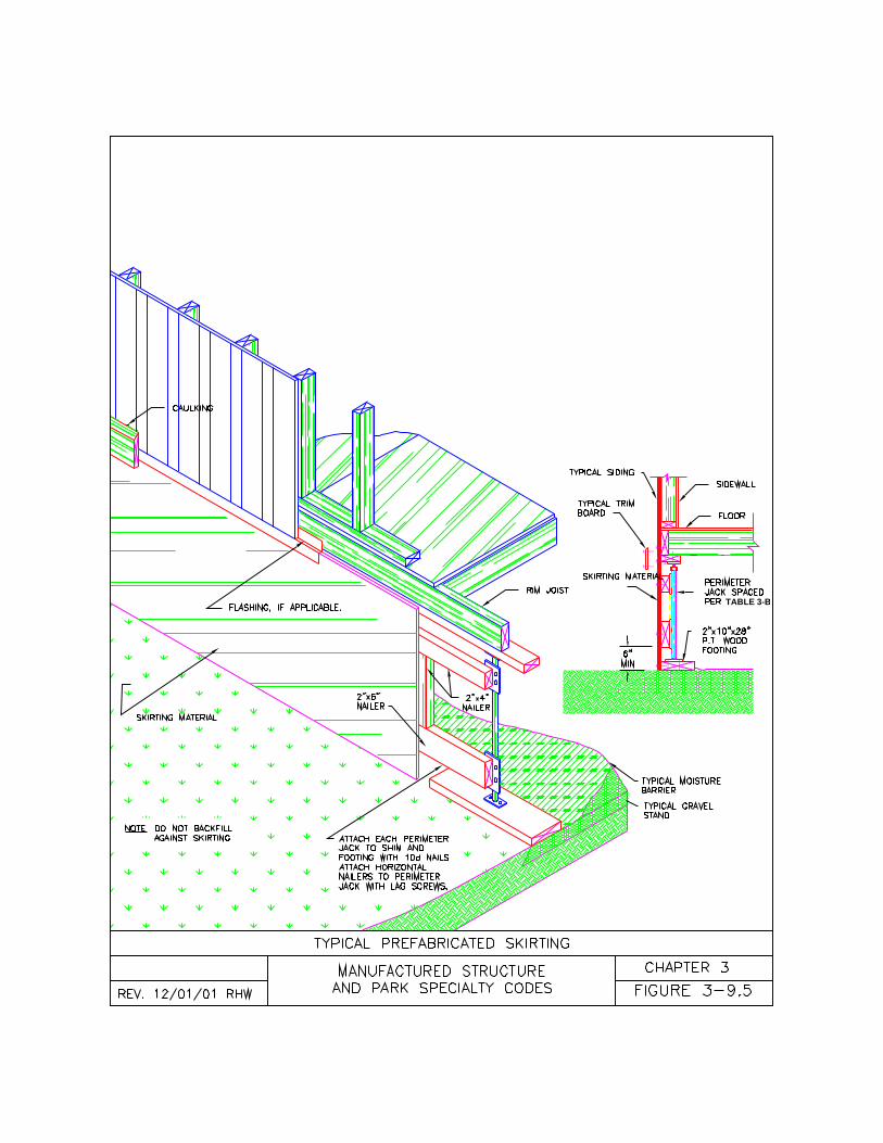
TABLE 3-B
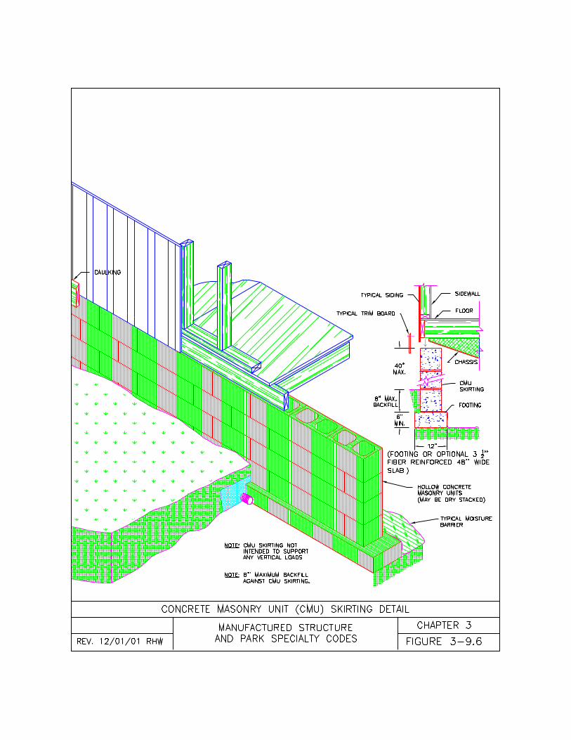
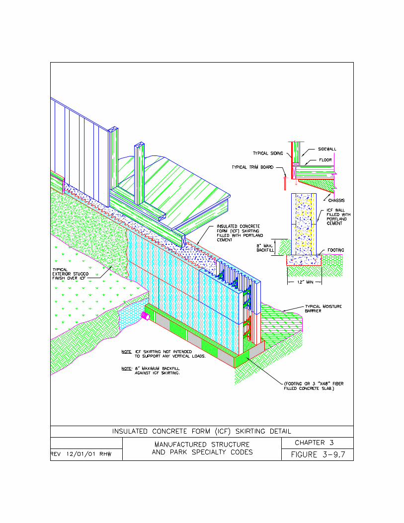
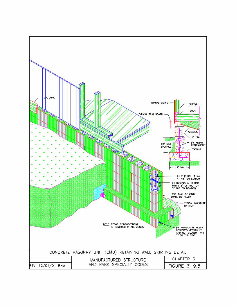
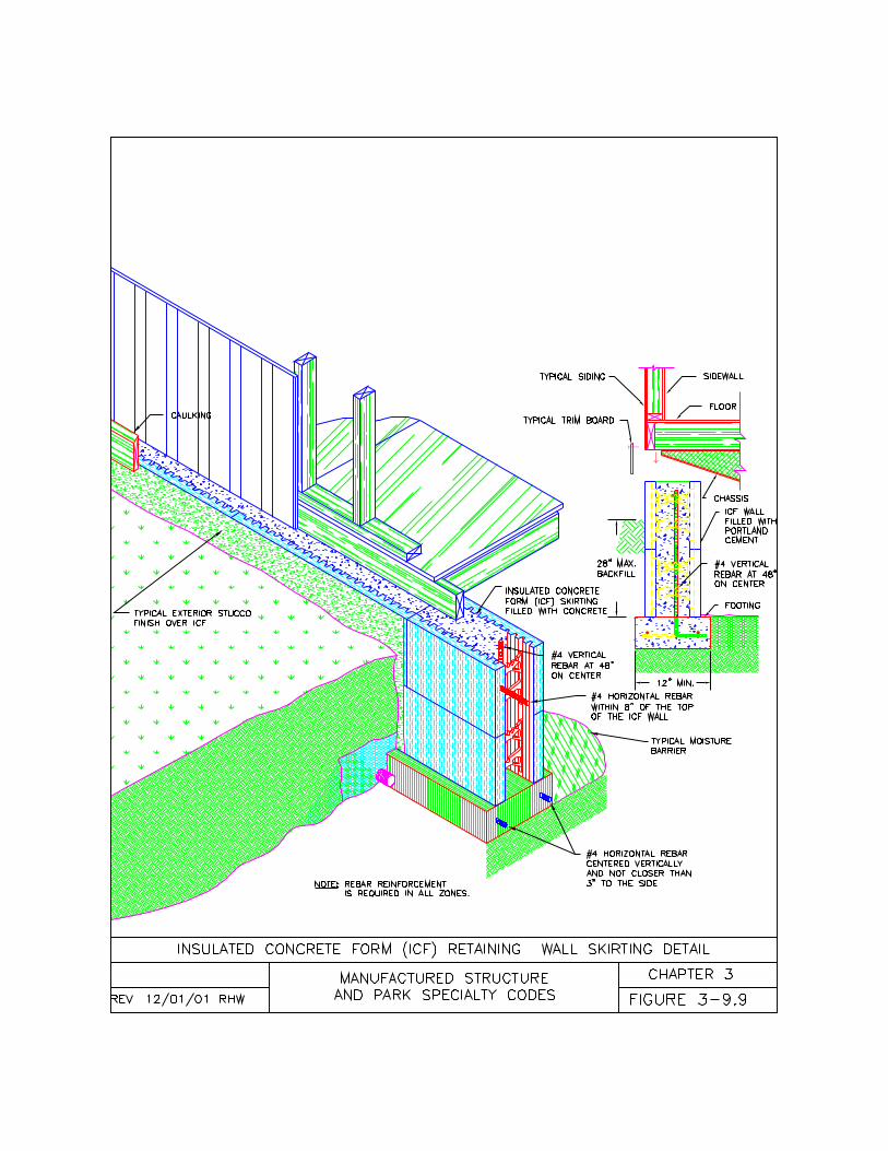
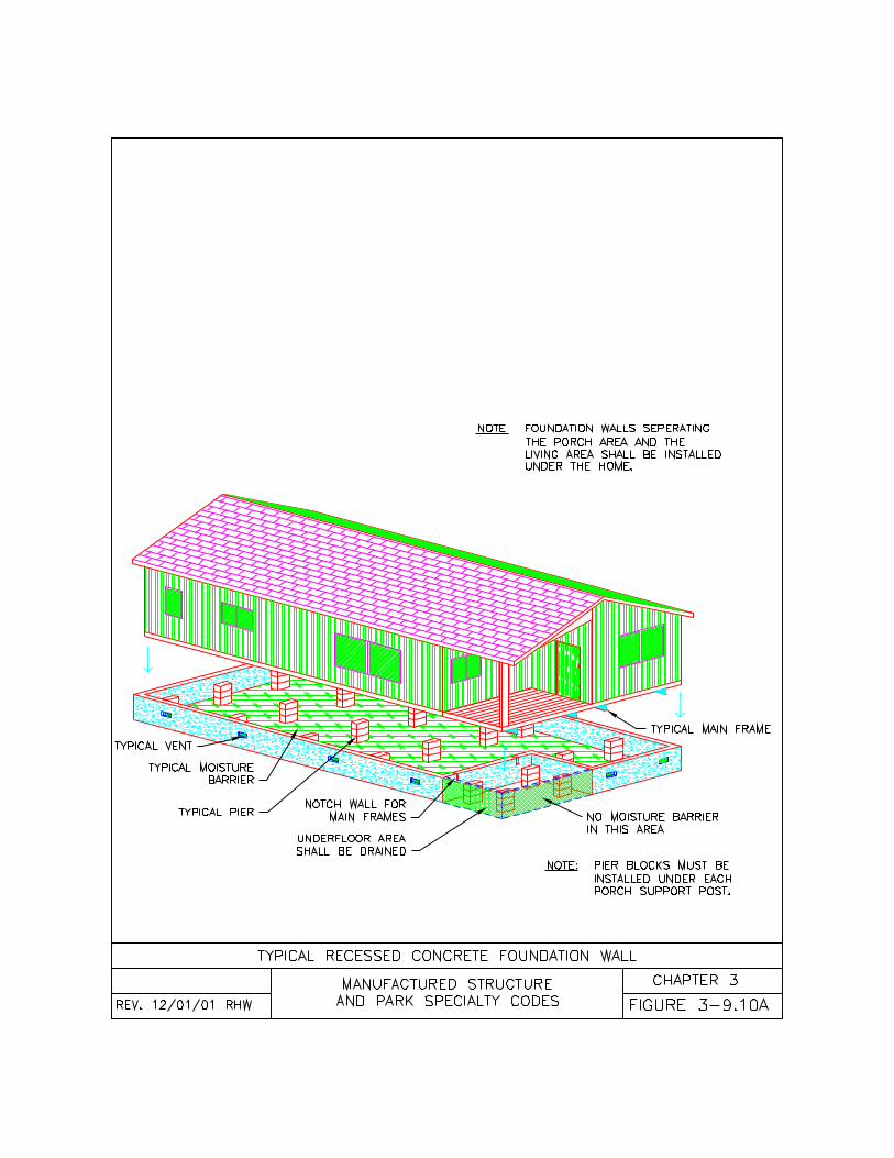
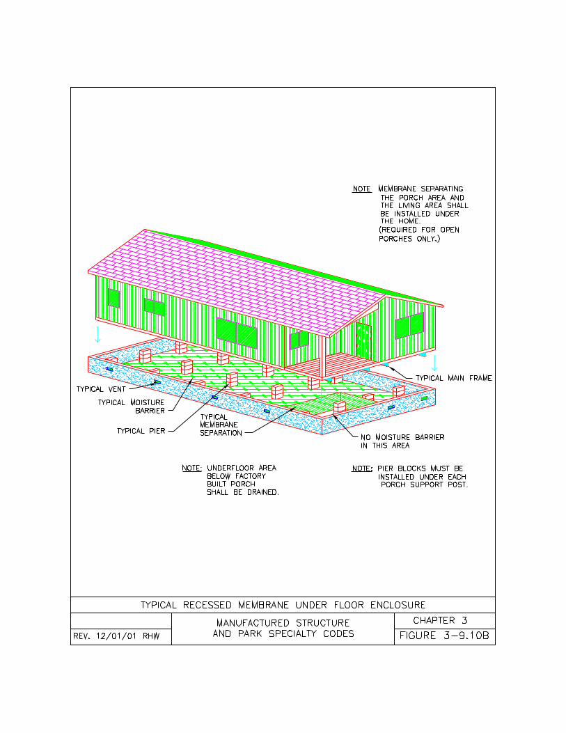
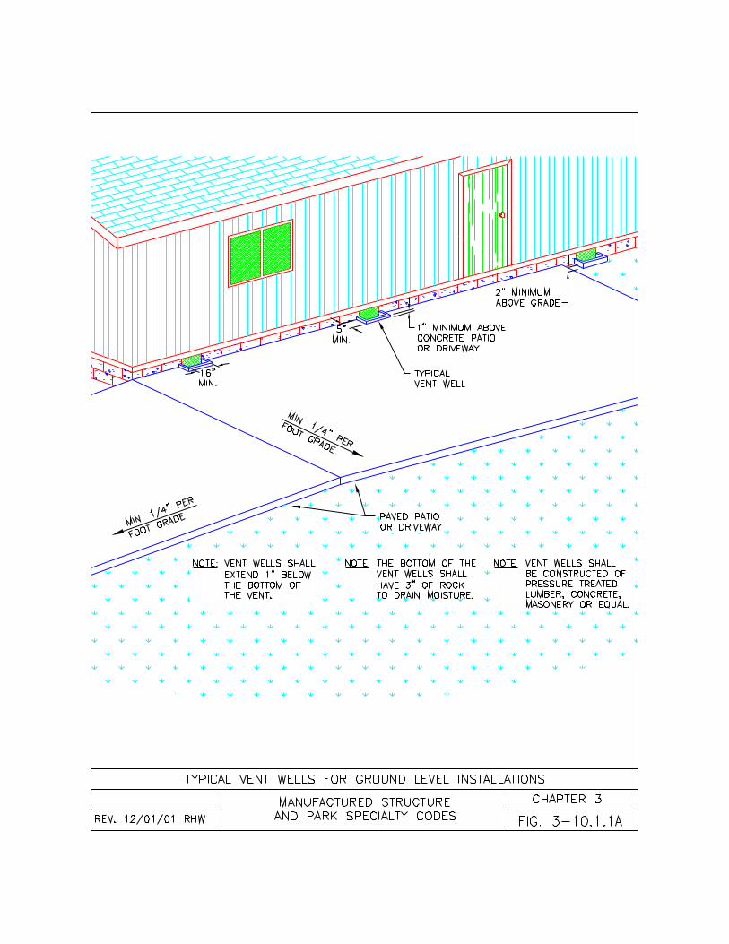
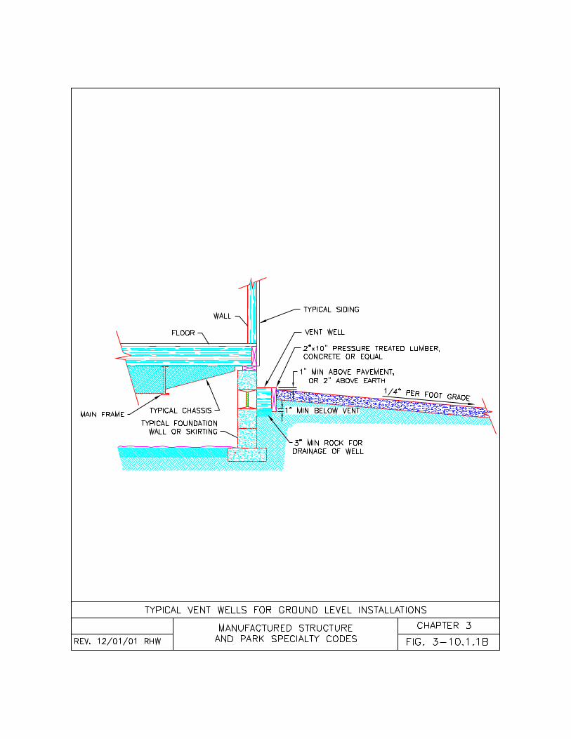
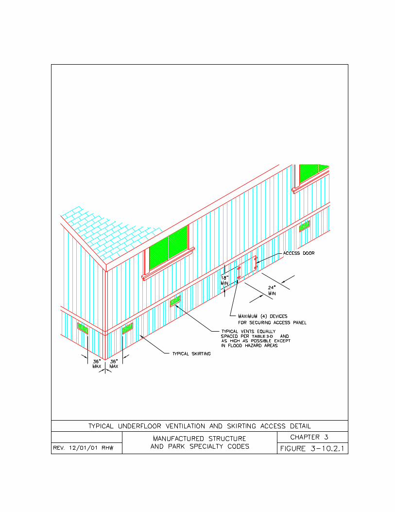
TABLE 3-D
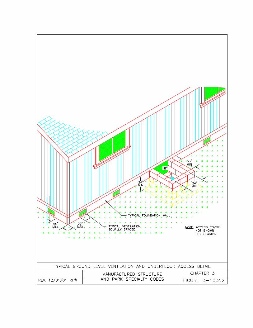
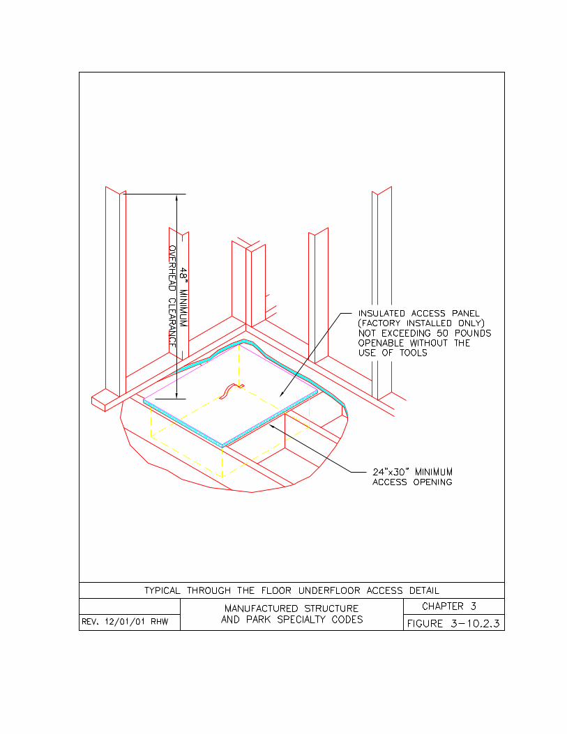
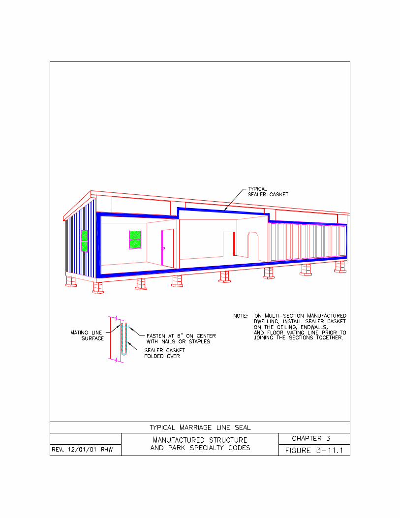
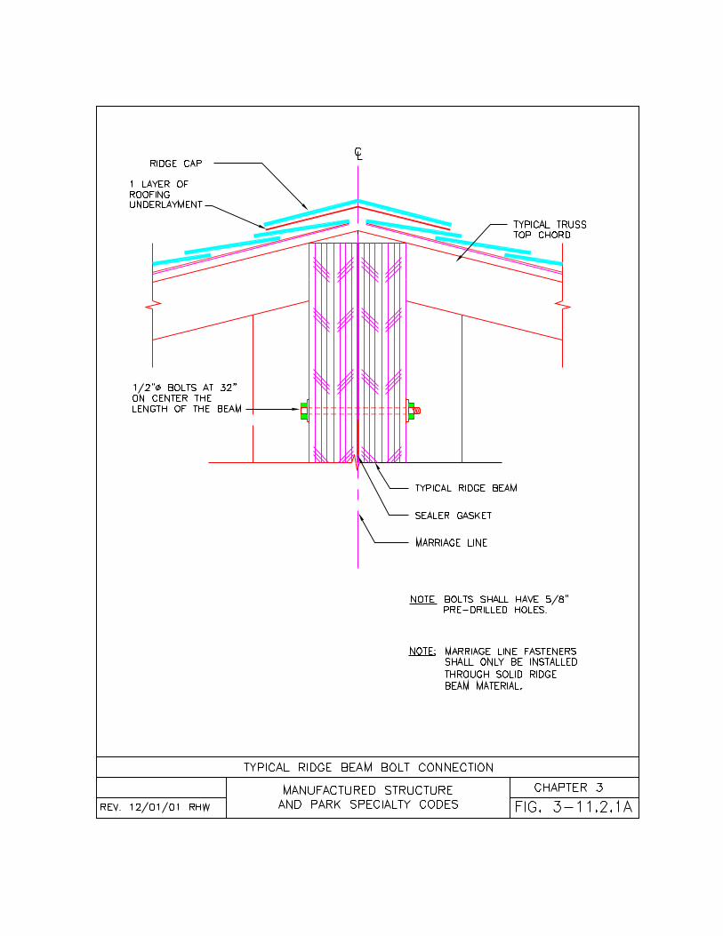
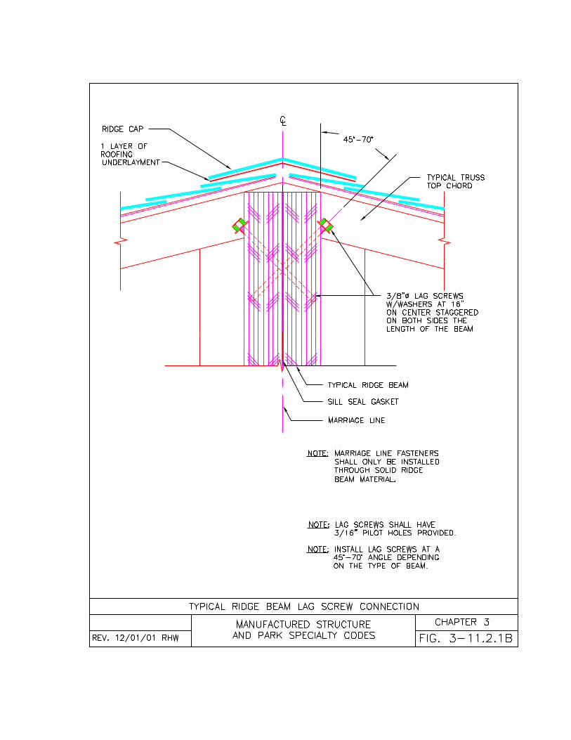
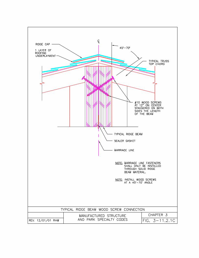
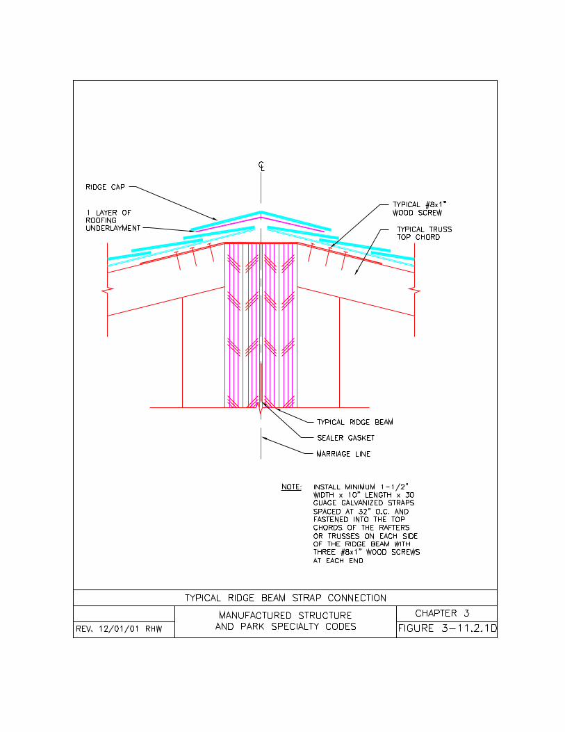
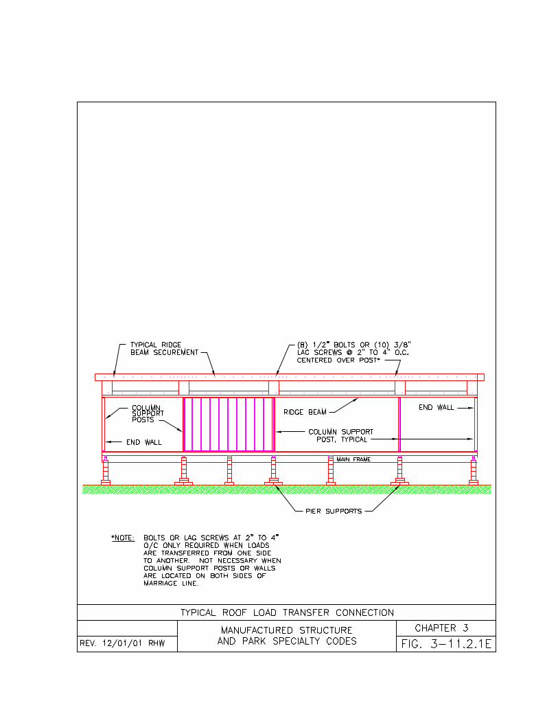
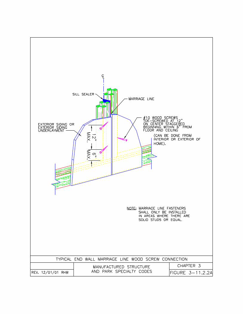
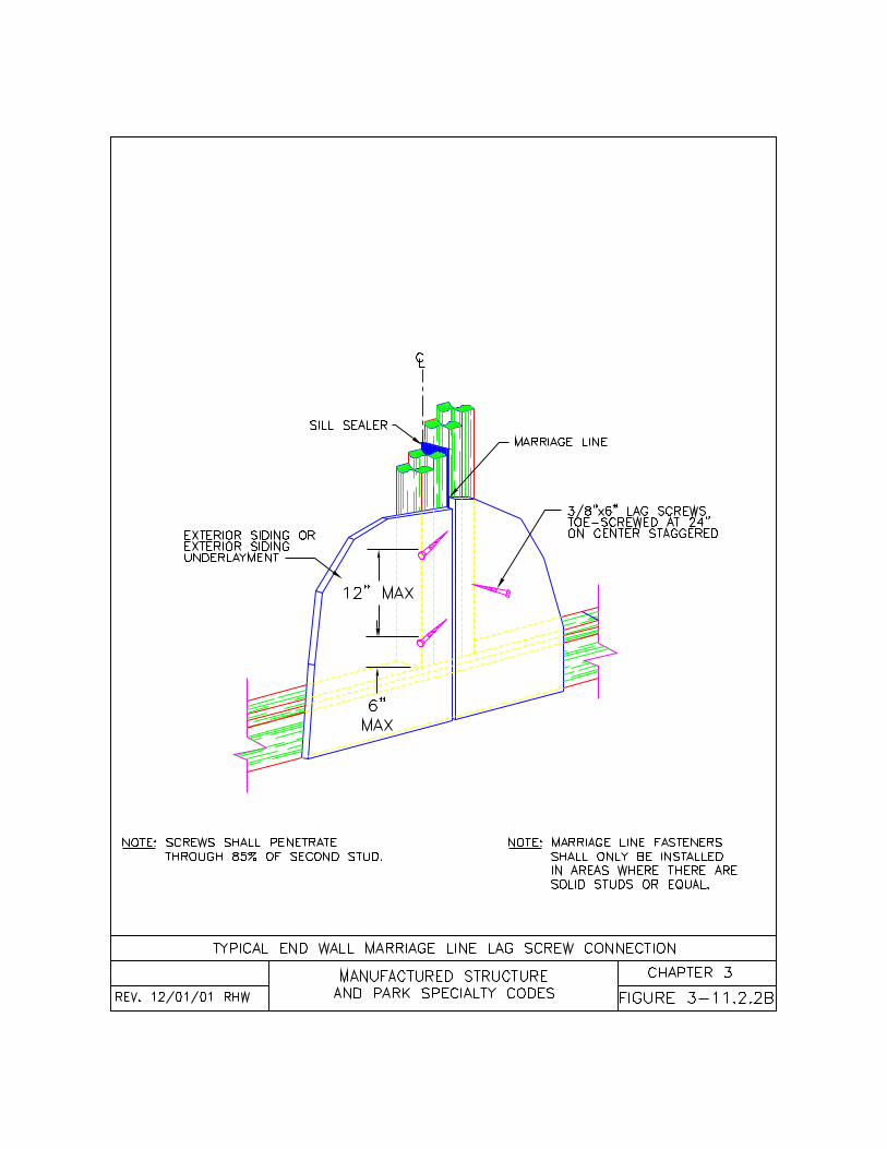
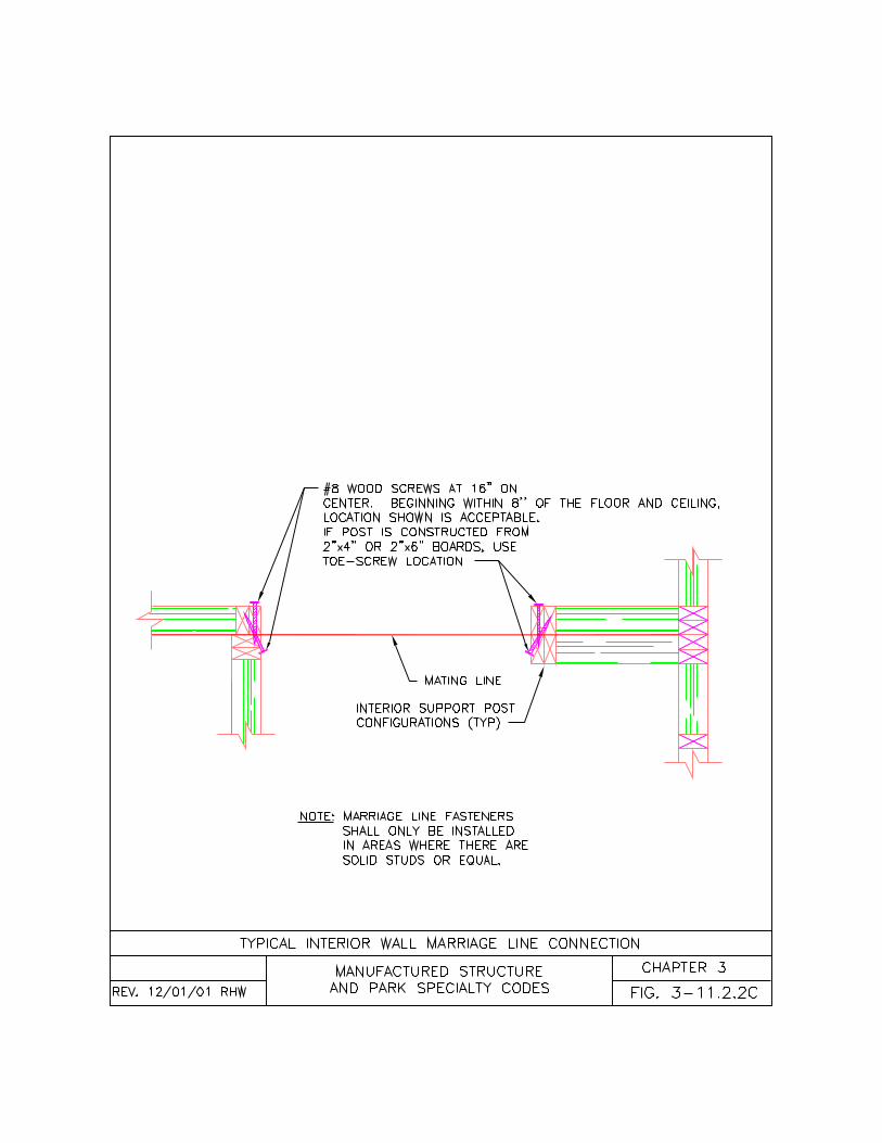
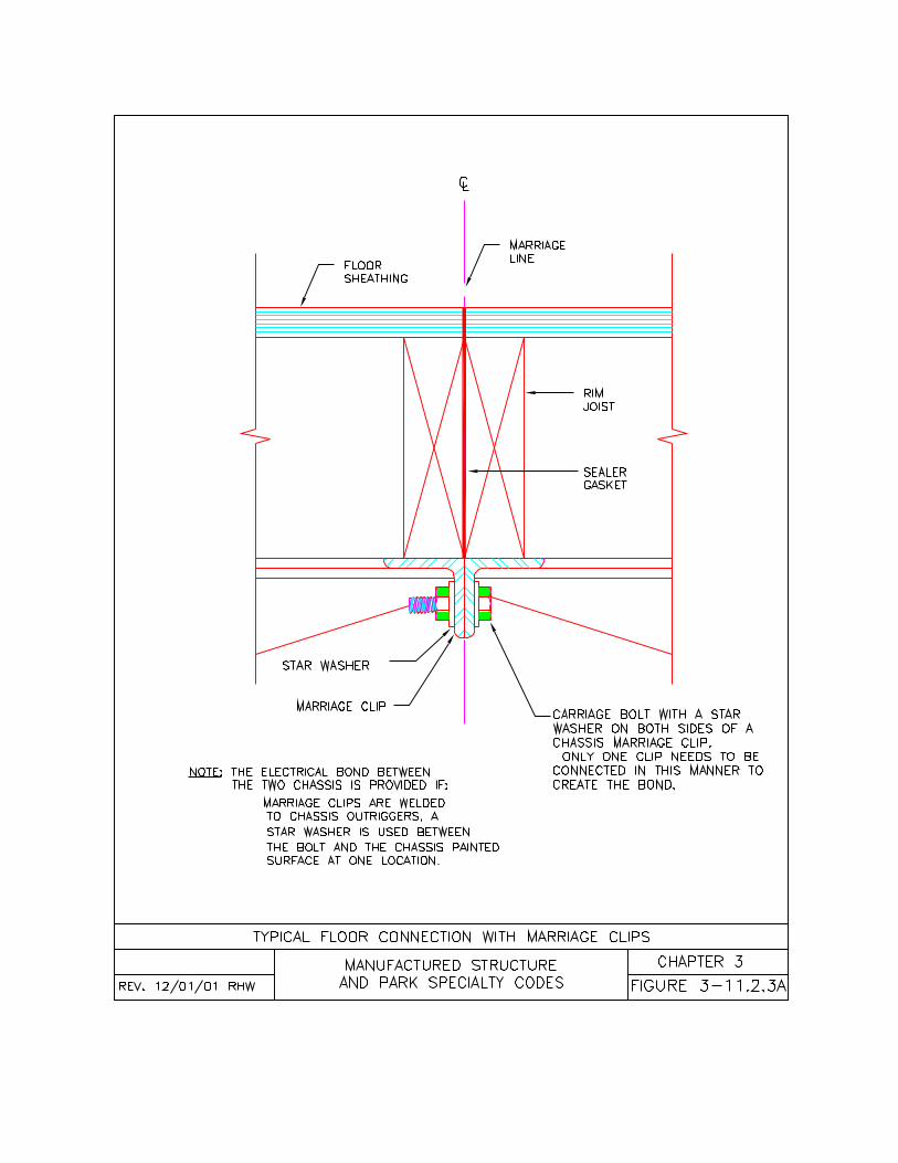
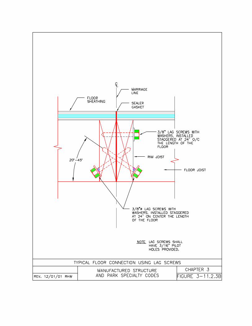
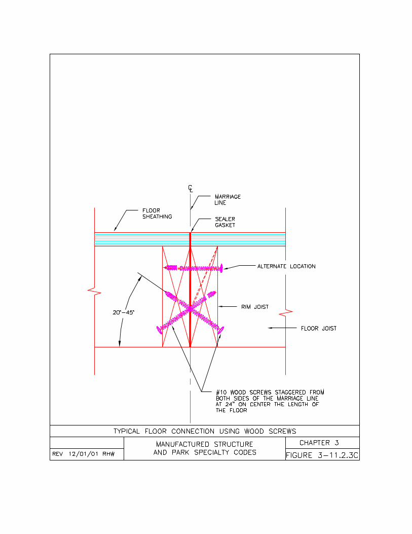
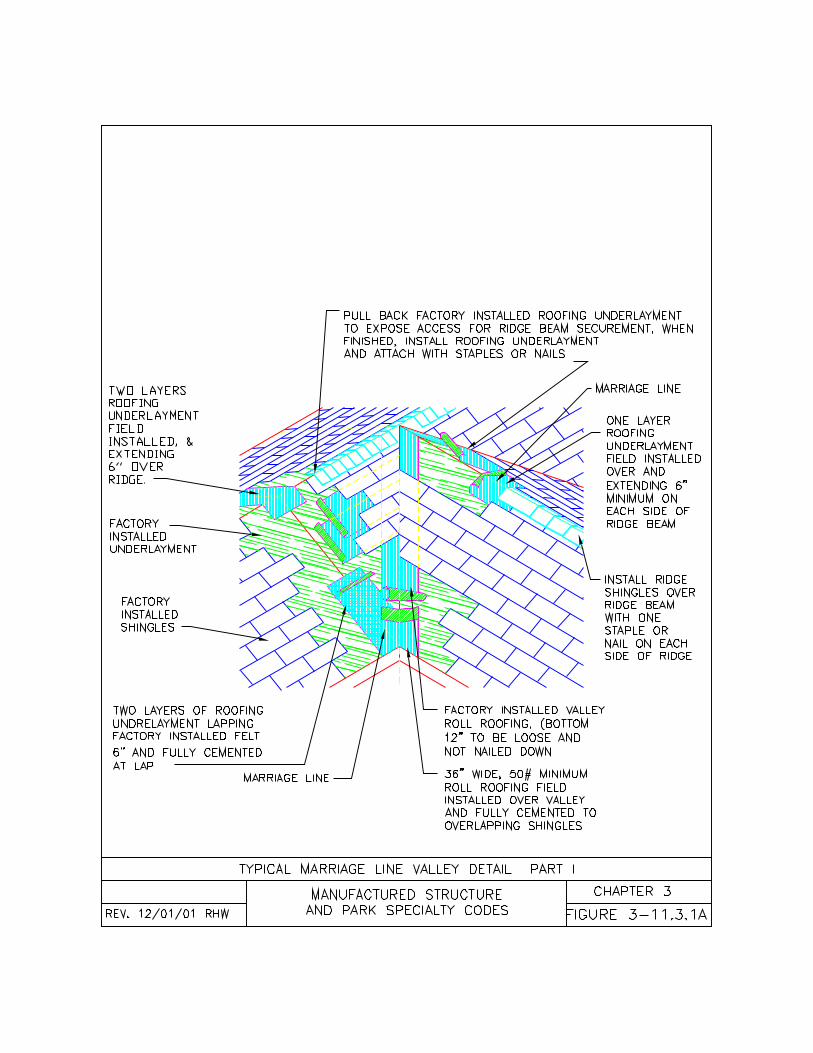
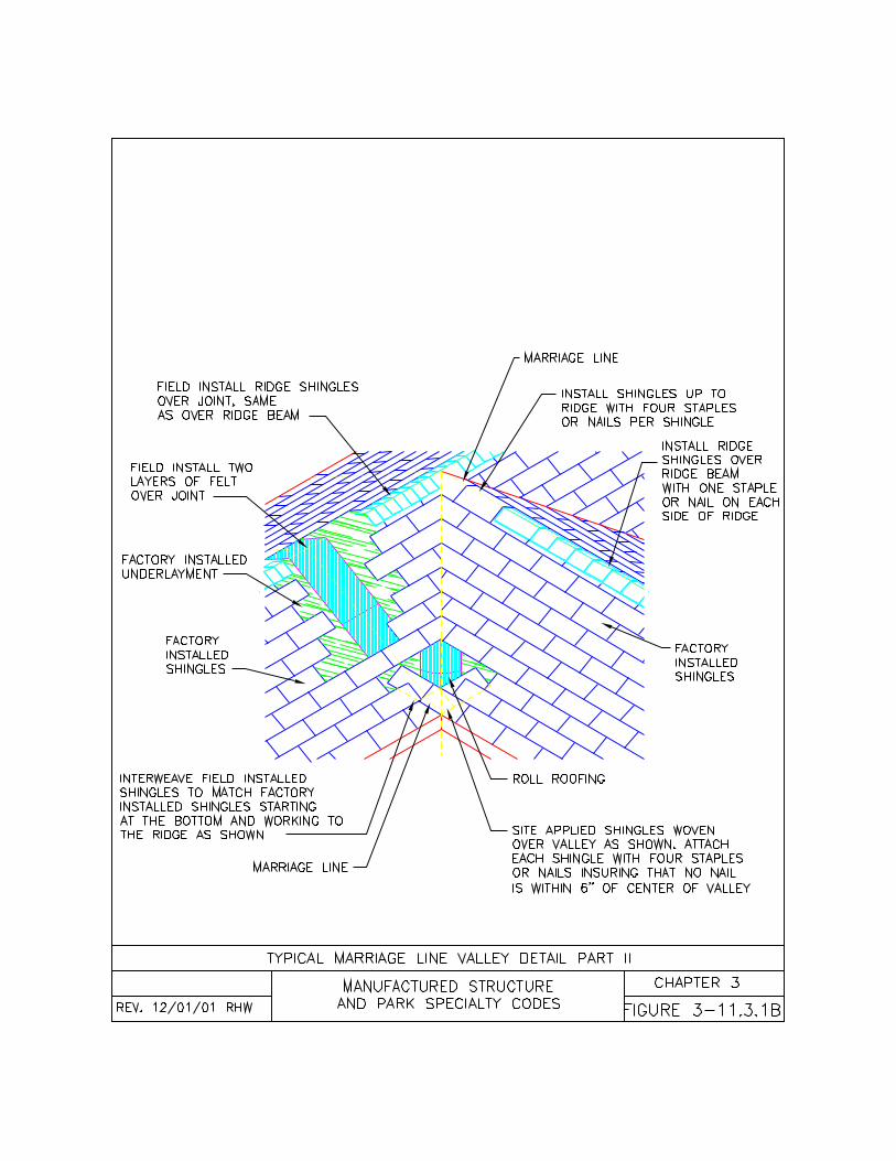
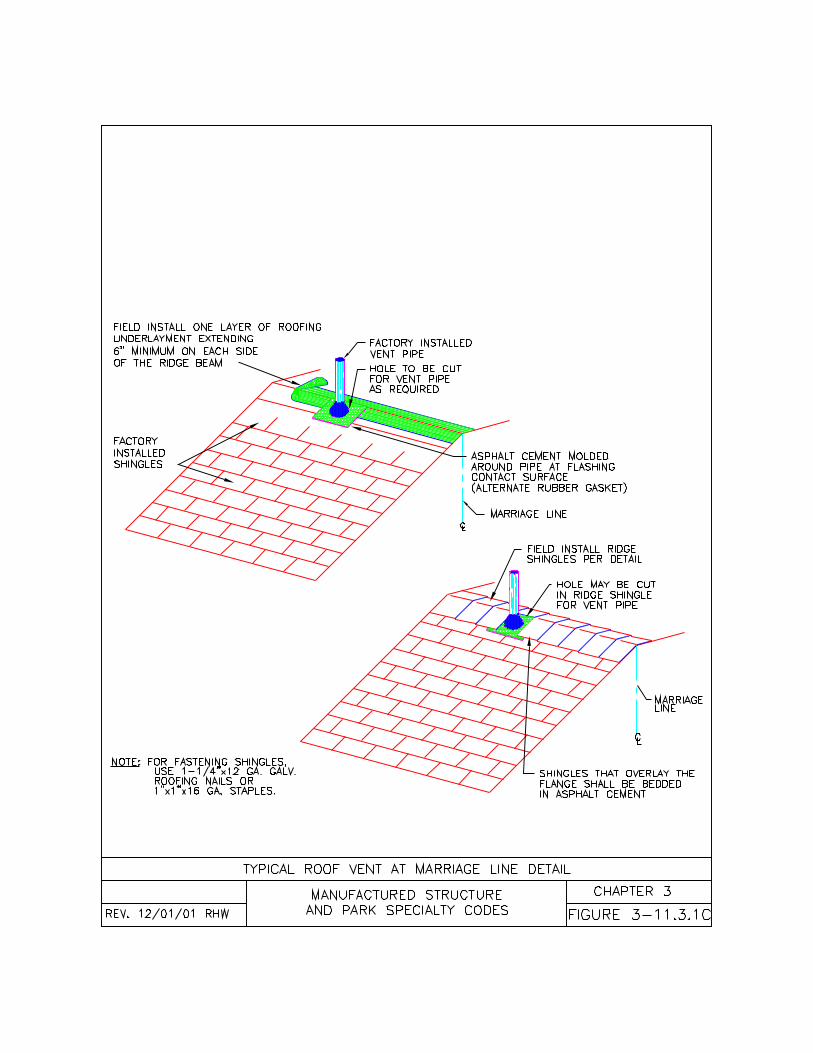
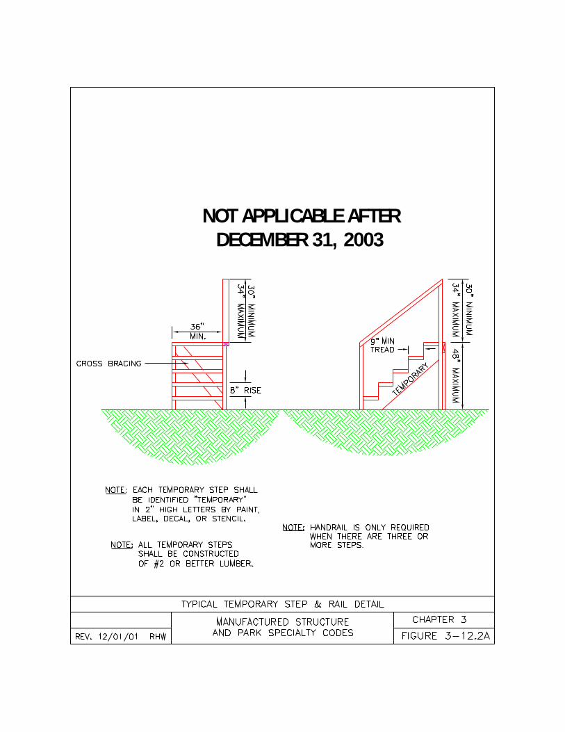
NOT APPLICABLE AFTER DECEMBER 31, 2003
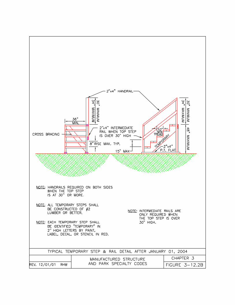
71
CHAPTER FOURELECTRICALINSTALLANTIONS/CONNECTIONS
4-1 General4-2 Electrical Feeders4-3 Service Equipment4-4 Crossover Connections4-5 Electrical Equipment4-6 Electrical Testing
4-1 General.4-1.1 Electrical Installations. Thischapter of the code is intended tosupplement the National Electrical Code(NEC) concerning manufactureddwellings and manufactured dwellingparks, but is not intended to take theplace of the NEC or the federalManufactured Home Construction andSafety Standards 24 CFR 3280.(a) Wherever the requirements of thiscode differ from the NEC, this code shallapply;(b) Alternate methods permitted in theNEC but not mentioned in this code maybe permitted if acceptable to the authorityhaving jurisdiction;(c) All electrical equipment shall bewithout defect; damaged materials orequipment cannot be used. Usedelectrical equipment shall be examinedfor defect prior to installation, and alldamaged electrical materials orequipment shall be repaired withapproved component parts, or replaced;(d) All electrical equipment, materials,devices, appliances, and fittings shall belisted and labeled for it’s intended use,and installed according to this code andwhere not specific, to the NEC.
4-1.2 Manufactured Dwellings. Allelectrical installations in connection with amanufactured dwelling installation,alteration, repair, conversion, or additionto a manufactured dwelling shall be madeaccording to this code and, where notspecific, to the NEC.(a) See Chapter 9 for smoke alarm andsmoke detector locations.
(b) When a manufactured dwelling islocated in a flood hazard area, allelectrical connections on the lot shall be aminimum of 12 inches (30 cm) above thebase flood level.
4-1.3 Accessories. All electricalinstallations to external equipment,alterations, repairs, conversions, oradditions in connection with amanufactured home shall be madeaccording to this code and, where notspecific, to the NEC. External accessories(i.e., accessory buildings, structures, airhandling equipment, and water and sewerpumps) may be connected directly to themanufactured dwelling’s main distributionpanel if there is adequate space andamperage to supply the added loads.Except where otherwise required byChapter 6 for fuel burning equipment,replacement appliances are not requiredto be listed for manufactured home use.See Section 4-5 for additionalrequirements for onsite installedequipment.
4-1.4 Underground Installations. Directburied cables shall be installed intrenches and protected from damageaccording to Table 4-D. Backfill shall befree of large rocks, paving materials,cinders, large or sharply angularsubstances, or corrosive material.Backfill around cables with sand or cleansoil (see Figures 4-1.4A and B). Directburied cables shall maintain the minimumclearances shown in Table 4-D.Do not install direct burial cables in acommon trench with non-electrical utilitiesunless specifically approved by theelectrical utility company or the authorityhaving jurisdiction.
4-1.5 Communication Equipment.Communication cables (i.e. telephone,television, and computer cables) may beinstalled by the manufacturer, however, ifthe purchaser did not order the home tobe pre-wired, cables will need to beinstalled on site. Manufactured dwellingfloor, wall, and ceiling cavities contain
72
electrical circuits, plumbing, and ducting.Extreme care should be exercised duringdrilling through and placingcommunication cables within thesecavities. Communication cables installedin trenches with other electricalconductors shall be separated by aminimum of 12 inches (30 cm) (seeFigure 4-1.4B).
4-1.6 Clearances. Maintain allclearances to electrical equipmentaccording to the listing of the equipment,the NEC, Tables 4-C and 4-D. Electricalequipment or materials shall not obstructthe access to the under-floor area.Homes may not be sited less than eight(8) feet (243.8 cm) from a transformer.
4-1.7 Repairs and Maintenance. Allrepairs and maintenance of amanufactured dwelling electrical systemshall be made according to this code, andwhere not specific, to the 24 CFR 3280 orto the NEC.
4-1.8 Alterations and Additions. Allalterations and additions to amanufactured dwelling electrical systemshall be made according to this code, andwhere not specific, to the 24 CFR 3280 orto the NEC.
4-1.9 Inspections. All electricalconnections shall be accessible forinspections. All excavations containingelectrical equipment shall be left open forinspection by the authority havingjurisdiction.
4-2 Electrical Feeders.4-2.1 Approved Feeders. Manufactureddwelling feeder conductors shall consistof one of the following:(a) A listed factory installed or providedcord, properly connected. (see figure 4-2.1A);(b) A permanently installed overheadfeeder containing four insulatedconductors listed as sunlight resistant and
installed in compliance with Table 4-A.(see figure 4-2.1B);(c) A permanently installed overheadfeeder containing three insulatedconductors listed as sunlight resistantwith an “uninsulated” messenger of afactory assembled quadraplex cableinstalled in compliance with the applicableprovisions of NEC Articles 230-24, 321,and 550-5 (see figure 4-2.1B);(d) A permanently installed undergroundfeeder containing four insulatedconductors as per Table 4-B;(e) A permanently installed feederinstalled by the manufacturer according toDAPIA approved plans when the serviceequipment is mounted on themanufactured dwelling by themanufacturer at the manufacturing plant;or(f) A permanently installed feedercontaining four insulated conductors, andprotected in an approved raceway in orthrough the floor, wall, or roof or underthe chassis when the service equipmentis mounted on the manufactured dwellingon site.
4-2.2 Feeder Sizing. Feeders shall besized according to the following:(a) The feeder size shall be based on theamperage of the main circuit breakerinside the manufactured dwelling’s maindistribution panel which is also indicatedon an exterior label located near thefeeder and on the manufacturer’s dataplate located inside the home.(b) Feeders shall be sized adequately tocarry the combined loads of themanufactured dwelling and all externalaccessories receiving power from themain distribution panel (i.e. airconditioner, heat pump, accessorybuildings, accessory structures, or waterand sewer pumps).(c) Overhead feeders shall be sizedaccording to Table 4-A.(d) Underground feeders and conduitshall be sized according to Table 4-B.
4-2.3 Feeder Installations. Feederconductors shall be installed according to
73
the following and, where not specific, tothe NEC:(a) Cord connected feeders shall consistof one listed 50 ampere power-supplycord attached to the main distributionpanel or a junction box. (see Figure 4-2.1A);(b) Overhead feeders shall be providedwith the clearances required in Table 4-C. (see figure 4.2.1B);1. When roof additions are installed on amanufactured dwelling, the height of theoverhead feeder shall be extended toprovide the required clearances abovethe roof addition; and (c) Underground feeders shall beprovided with the clearances required inTable 4-D, and where not specific, toNEC Table 300-5;(d) Conduit shall be sized according toTable 4-B;(e) Conduit shall be installed and securedat the intervals required in Table 4-E;(f) The feeder shall be connected to theelectrical service disconnect within viewof the manufactured dwelling and within30 feet (914 cm) of the manufactureddwelling exterior wall. The 30 foot (914cm) measurement applies to the servicedisconnect only. If the meter is not part ofthe service disconnect, the meter is notrequired to be within 30 feet (914 cm) orwithin view of the manufactured dwelling.
4-2.4 Grounding. The green coloredinsulated conductor of the feeder shall beconnected to the grounding bus inside themain electrical distribution panel and tothe grounding bus inside the serviceentrance equipment located on oradjacent to the manufactured dwelling.The neutral bar shall be isolated from theground bar inside the main distributionpanel or inside any junction boxes used inconjunction with the manufactureddwelling branch circuit or feeder.
4-2.5 Temporary Feeder Installations.When a manufactured dwelling isinstalled for display purposes only on amanufacturer’s, dealer’s or distributor’s lotor facility, or at a show the electrical
feeders may be installed according to thefollowing:(a) Temporary feeders may be reduced insize and amperage adequate to supplyonly the equipment being used during thedisplay;(b) Temporary feeder disconnects areexempt from requirements to be withinview and within 30 feet (914 cm) of themanufactured dwelling exterior wall;(c) Temporary feeders supplying only 120volt circuits may be made up of threeinsulated conductors and may useservice entrance (SE) cable;(d) Temporary feeders shall provide ameans of grounding the manufactureddwelling to an approved electrical ground;and
4-3 Electrical Service Equipment.4-3.1 Service Equipment. Amanufactured dwelling shall be providedpower through electrical serviceequipment installed according to thiscode and, where not specific, to NECArticle 230 and 550-23 of the NationalElectrical Code (NEC).
4-3.2 Service Equipment Installations.Service equipment shall be provided for amanufactured dwelling by one of thefollowing methods:(a) Service equipment may be installedon the manufactured dwelling by themanufacturer at the manufacturing plantduring the initial construction (see Figure4-3.2A);(b) The service equipment may be fieldinstalled on the manufactured dwelling atits final installation site (see Figures 4-3.2A);(c) The service equipment may beinstalled on a pole or as an approvedpedestal adjacent to the manufactureddwelling; or(d) When service equipment is installedon a permanent detached structure (i.e.garage, cabana, or accessory building)on the same site it must be within 30 feet(914 cm) and in sight of the manufactureddwelling, or a disconnect means may be
74
provided within 30 feet (914 cm) and insight of the manufactured dwelling.
4-3.2.1 Factory Installed ServiceEquipment. Service equipment installedon a manufactured dwelling by themanufacturer in the factory shall complywith the following:(a) Service equipment may be installedby the manufacturer at the manufacturingplant during the initial construction;(b) The neutral conductor shall beconnected to the system groundingconductor on the supply side of the maindisconnect; and(c) Service equipment shall be sitespecific and sized adequately to carry thecombined loads of the manufactureddwelling.
4-3.2.2 Field Installed ServiceEquipment. Service equipment installedon a manufactured dwelling at themanufactured dwelling site shall complywith the following:(a) Service equipment shall be installed ina manner acceptable to the authorityhaving jurisdiction;(c) Service equipment and conductorsshall be sized adequately to carry thecombined loads of the manufactureddwelling.(d) The neutral conductor shall beconnected to the system groundingconductor on the supply side of the maindisconnect; and(e) Location of the service meteringequipment shall be site specific accordingto the requirements of the local utilitycompany.
4-3.2.3 Detached Service Equipment.Service equipment installed on amanufactured dwelling site and notattached to the manufactured dwellingshall comply with the following:(a) Service equipment shall be installedon a pole or as an approved pedestal orinstalled on a permanent structureadjacent to the manufactured dwelling(i.e. garage, cabana, or accessorybuilding);
(b) Service equipment and conductorsshall be sized adequately to carry thecombined loads of the manufactureddwelling and all external accessories onthe manufactured dwelling.
4-3.3 Service Location and Clearances.All service equipment shall be locatedaccording to the following:(a) Service equipment shall be locatedaccording to the site’s electrical serviceas designated by the applicable electricalutility company or if in a park, accordingto the electrical service designed for thepark;(b) Overhead service conductors shallmaintain the clearances required in Table4-C; (See Figure 4-2.1B)1. When roof additions and ramadas areinstalled on a manufactured dwelling, theheight of the overhead service shall beextended to provide the requiredclearances above the roof addition.(c) Underground service conductors shallmaintain the clearances required by theserving utility;(d) The electrical service disconnect shallbe within view of the manufactureddwelling and within 30 feet (914 cm) ofthe manufactured dwelling exterior wall;(e) Service disconnect shall be located sothe bottom of the enclosure containingthe disconnecting means is not less than2 feet (61 cm) above finished grade or thebase flood elevation when themanufactured dwelling is located in aflood hazard area;(f) The center of the meter shall belocated a minimum of 4 feet (122 cm) anda maximum of 6 feet (183 cm) abovegrade or a working platform;(g) Service disconnect shall be located sothe center of the grip of the operatinghandle, in its highest position, is not morethan 79 inches (201 cm) above thefinished grade or a working platform; and(h) The front of the service equipmentshall be provided with a workingclearance of 30 inches (76 cm) wide by36 inches (91 cm) deep.
75
4-3.4 Service EquipmentRequirements. All service equipmentshall be installed according to thefollowing:(a) All service equipment shall beinstalled according to this code and,where not specific, to NEC Article 230and 550-23;(b) All electrical service equipmentconnections shall be accessible;(c) All service equipment shall contain ameans for connecting accessorybuildings, accessory structures, oradditional electrical equipment locatedoutside a manufactured dwelling by afixed wiring method; and(d) When there is multiple electricalservice equipment on the same lot,space, or site, each service disconnectshall be identified with a permanent,prominently displayed identification labelindicating what structure or accessory theservice disconnect controls (i.e.manufactured dwelling, accessorybuilding, air handling equipment, andwater and sewer pumps)
4-3.5 Grounding. Where serviceequipment is mounted on themanufactured dwelling and themanufactured dwelling is supported by apoured-in-place concrete footing or slab,the service equipment may be groundedto a concrete encased electrodeaccording to NEC Article 250-50 (seeFigure 3-8.2.1 and 3-8.2.2). Where apoured-in-place concrete footing or slabground is not available, the manufactureddwelling service equipment shall begrounded to ground rod(s) or othermethods according to NEC Article 250-50 or 250-52.
4-4 Electrical Crossover Connections.4-4.1 Crossover Connection. Multiplesections (i.e. side by side or stackedsections) of manufactured dwellings shallhave the electrical circuits connected atthe marriage line according the following:(a) All electrical crossover connectionsshall be a minimum of 12 inches (30 cm)above the base flood level;
(b) All electrical crossover connectionsshall be made with approved connectorsand contained within junction boxes orwithin wall or floor cavities;(c) All electrical crossover connectionsshall remain accessible; and(d) Electrical crossover connections atthe marriage line shall be made accordingto Section 4-4.2 or 4-4.3 of this chapter.
4-4.2 Component InterconnectionDevices. When provided by themanufactured dwelling manufacturer,multiple sections of a manufactureddwelling may be connected through listedand approved component interconnectiondevices (i.e. AMP®, Molex®, or equalconnectors) according to the following(see Figures 4-4.2A):(a) Each component interconnectiondevice shall be matched with a similarconnector identified by the manufacturerwith corresponding colors, numbers,letters, or other marks;(b) Each pair of componentinterconnection devices shall beconnected and locked according to thedevice manufacturer’s installationinstructions;(c) The connected pair of componentinterconnection devices shall be pushedback inside the floor or wall cavity; and(d) The access panel on the wall or floorshall be replaced and secured in place.
4-4.3 Hard Wire Connections. Whenprovided by the manufacturer of themanufactured dwelling, multiple sectionsof a manufactured dwelling may beconnected through junction boxesaccording to the following:(a) The cables shall be inserted into thejunction boxes and secured withapproved clamps where required;(b) Each cable shall have the sheathingstripped back exposing the conductorsand each conductor shall have theinsulation stripped back exposing thebare wire;(c) Each cable, containing three to fourconductors, shall be matched withanother cable identified by the
76
manufacturer with corresponding colors,numbers, letters, or other marks;(d) The conductors of each matchedcircuit shall be joined together accordingto their identification with appropriatelysized wire nuts. There shall not be anyexposed bare conductors showingoutside the wire nuts except for thegrounding conductor (see Figure 4-4.3Aand 3B);(e) The bare conductors and greenconductors (grounding conductors) of allcircuits shall be joined together with awire nut or other approved device;(f) Where the junction box is metal, itshall be bonded to the groundingconductors inside the box;(g) Wire nut connections shall bechecked to make sure there are no looseconductors;(h) The conductors shall be pushed intothe box and the junction box coversecured in place.(i) All exposed cables shall be inside thewall or floor or shall be protected in anapproved conduit; and(j) Split circuits provided by themanufacturer shall be connectedaccording to the color-coding or othercoding provided by the manufacturer (seeFigure 4-4.3B).
4-4.4 Bonding Crossover. Multiplesections of manufactured dwellings shallbe bonded at each marriage lineaccording to one of the followingmethods:(a) Each steel chassis shall be bonded tothe adjacent chassis with a solid orstranded, green insulated or bare number8 copper conductor secured toconnectors supplied by the manufacturer(see figure 4-4.4A); or(b) Each steel chassis shall be bonded tothe adjacent chassis with bolts or rodscapable of conducting current from onechassis to another. Star washers orsimilar paint penetrating devices shall beused to provide an effective bonding pathbetween each chassis (see figure 4-4.4B).
4-5 Electrical Equipment.4-5.1 Site Connections. All site installedor connected electrical equipment shallbe installed according to this code and,where not specific, to the NationalElectrical Code (NEC).4-5.2 Shipped-Loose Fixtures. Electricalequipment and fixtures (i.e. ceiling fans,chandeliers, exterior lights, andmechanical equipment) that are shipped-loose with the manufactured dwellingshall be installed on site according to theequipment manufacturer’s installationinstructions.Wiring connections of shipped-looseelectrical equipment or fixtures shall beproperly connected to the correspondingcolor coded or marked conductors of themanufactured dwelling branch circuitconductors. When fixtures are located ona combustible surface (i.e. hardboard,wood, logs, vinyl, etc.) install a flash ringbetween the electrical device and thecombustible surface.
4-5.3 Site Installed ElectricalEquipment. All site installed electricalequipment and the electrical connectionsshall comply with the following:(a) Outdoor fixtures and equipment shallbe listed for use in wet locations, exceptthey may be listed for use in damplocations if located on the underside ofthe home or located under roofextensions or similarly protectedlocations;(b) Exterior air handling equipment (i.e.air conditioners, heat pumps, andevaporative coolers) installed on theoutside of the manufactured dwellingshall be connected to an adequatelysized circuit;(c) Connections from the branch circuitjunction box to exterior air handlingequipment shall be made through liquidtight flexible conduit with the propertermination fittings;(d) Added accessories (i.e. accessorybuildings, accessory structures, airhandling equipment, and water and sewerpumps) not provided for by themanufacturer may be connected to the

77
manufactured dwelling’s main distributionpanel if there is adequate space andamperage to supply the additional branchcircuit loads;(e) Circuit breakers and conductors foradded accessories or appliances shall besized adequately according to the loadimposed;(f) Additional 120 volt, 15 or 20 amperereceptacles shall be permitted forconnection of electrical equipmentlocated outside the manufactureddwelling if protected by a listed groundfault circuit interrupter;(g) When a manufactured dwelling islocated in a flood hazard area, allelectrical appliances and connectionsshall be a minimum of 12 inches (30 cm)above the base flood level;(h) Under-floor or under-chassis line-voltage (120 volts, nominal or higher)wiring shall be protected from damage inan approved conduit closely routedagainst and secured to the floor orchassis;(i) Electrical raceways shall be supportedaccording to Table 4-E; and(j) All electrical appliances, equipment,and connections shall be accessible andremovable.
4-5.4 Electrical Ground. All site installedor connected electrical equipment shallbe grounded according to the following:(a) All 240 volt cooking ranges andclothes dryers shipped-loose orpurchased separately by the homeowner,shall have the bonding strap, if any,between the ground and neutralconductors removed before installation.(b) Cord sets used on 240-volt appliances(i.e. cooking ranges and clothes dryers)shall have four conductors and fourprongs when connected to amanufactured dwelling.(c) Cord sets for permanently installed110-volt appliances (i.e. built inmicrowave ovens, pellet-fired appliances,window air conditioners, etc.) shall havethree conductors and three prongs whenconnected to a manufactured dwelling.
4-5.5 Heat Tape Installation. Heat tape,when used, shall be connected to theheat tape receptacle outlet under themanufactured dwelling near the mainwater inlet. Heat tape shall be listed formanufactured home use and installedaccording to the heat tape manufacturer’sinstallation instructions.
4-6 Electrical Testing.4-6.1 Required Tests. Eachmanufactured dwelling shall be tested bythe person making the electrical feederconnection. When tests indicate faults,correct or report such failures to themanufacturer’s service departmentimmediately.
4-6.2 Polarity Tests. After all electricalconnections have been made; themanufactured dwelling shall be testedaccording to the following:(a) All 120 volt electrical receptacleoutlets shall be subjected to a polarity testto determine that connections have beenproperly made;(b) All shipped-loose electrical fixturesshall be subjected to a polarity test todetermine that connections have beenmade properly; and(c) All shipped-loose 240-volt electricalappliances shall be visually checked ortested to assure the ground and neutralconductors have been isolated.
4-6.3 Continuity Test. After all electricalconnections have been made; themanufactured dwelling shall be testedwith the power off according to thefollowing:(a) All applicable metal parts in or on amanufactured dwelling shall be tested forcontinuity to ensure they are properlybonded; and(b) All grounding and bonding conductorsinstalled or connected during themanufactured dwelling installation shallbe tested for continuity.
4-6.4 Functional Tests. After allelectrical connections have been made;the manufactured dwelling shall be tested
78
with the power on according to thefollowing.(a) Each ground fault circuit interrupter(GFCI) shall be tested by pushing the testbutton and then reset by pushing thereset button. All receptacles protected bya GFCI shall be tested with a GFCIreceptacle tester to assure it is connectedand in working order; and(b) Each smoke detector shall be testedto assure it is connected and in workingorder.
4-6.5 Test Failures. Upon failure of anyof the above tests, check all applicablefield connections, correct any faults, andre-test. If tests continue to fail, notifyfactory authorized service personnelimmediately and report failures. Otherthan during testing, do not energize themanufactured dwelling until all faults inthe electrical system have beencorrected.
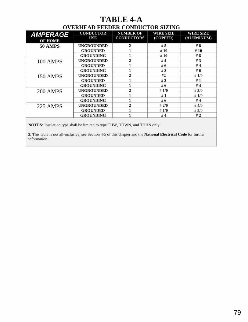
79
TABLE 4-AOVERHEAD FEEDER CONDUCTOR SIZING
AMPERAGEOF HOME
CONDUCTORUSE
NUMBER OFCONDUCTORS
WIRE SIZE(COPPER)
WIRE SIZE(ALUMINUM)
UNGROUNDED 2 # 8 # 8GROUNDED 1 # 10 # 10
50 AMPS
GROUNDING 1 # 10 # 8UNGROUNDED 2 # 4 # 3
GROUNDED 1 # 6 # 4100 AMPS
GROUNDING 1 # 8 # 6UNGROUNDED 2 #2 # 1/0
GROUNDED 1 # 3 # 1150 AMPS
GROUNDING 1 # 6 # 4UNGROUNDED 2 # 1/0 # 3/0
GROUNDED 1 # 1 # 1/0200 AMPS
GROUNDING 1 # 6 # 4UNGROUNDED 2 # 2/0 # 4/0
GROUNDED 1 # 1/0 # 3/0225 AMPS
GROUNDING 1 # 4 # 2
NOTES: Insulation type shall be limited to type THW, THWN, and THHN only.
2. This table is not all-inclusive, see Section 4-5 of this chapter and the National Electrical Code for furtherinformation.
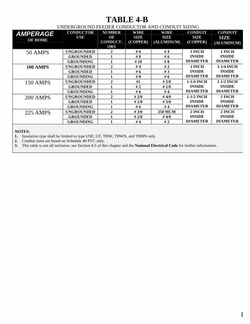
80
TABLE 4-BUNDERGROUND FEEDER CONDUCTOR AND CONDUIT SIZING
AMPERAGEOF HOME
CONDUCTORUSE
NUMBEROF
CONDUCT-ORS
WIRESIZE
(COPPER)
WIRESIZE
(ALUMINUM)
CONDUITSIZE
(COPPER)
CONDUITSIZE
(ALUMINUM)
UNGROUNDED 2 # 6 # 4GROUNDED 1 # 8 # 6
50 AMPS
GROUNDING 1 # 10 # 8
1 INCHINSIDE
DIAMETER
1 INCHINSIDE
DIAMETERUNGROUNDED 2 # 4 # 2
GROUNDED 1 # 6 # 3100 AMPS
GROUNDING 1 # 8 # 6
1 INCHINSIDE
DIAMETER
1-1/4 INCHINSIDE
DIAMETERUNGROUNDED 2 #1 # 2/0
GROUNDED 1 # 2 # 1/0150 AMPS
GROUNDING 1 # 6 # 4
1-1/4 INCHINSIDE
DIAMETER
1-1/2 INCHINSIDE
DIAMETER
UNGROUNDED 2 # 2/0 # 4/0GROUNDED 1 # 1/0 # 3/0
200 AMPS
GROUNDING 1 # 6 # 4
1-1/2 INCHINSIDE
DIAMETER
2 INCHINSIDE
DIAMETER
UNGROUNDED 2 # 3/0 250 MCMGROUNDED 1 # 2/0 # 4/0
225 AMPS
GROUNDING 1 # 4 # 2
2 INCHINSIDE
DIAMETER
2 INCHINSIDE
DIAMETER
NOTES:1. Insulation type shall be limited to type USE, UF, THW, THWN, and THHN only.2. Conduit sizes are based on Schedule 40 PVC only.3. This table is not all-inclusive, see Section 4-5 of this chapter and the National Electrical Code for further information.
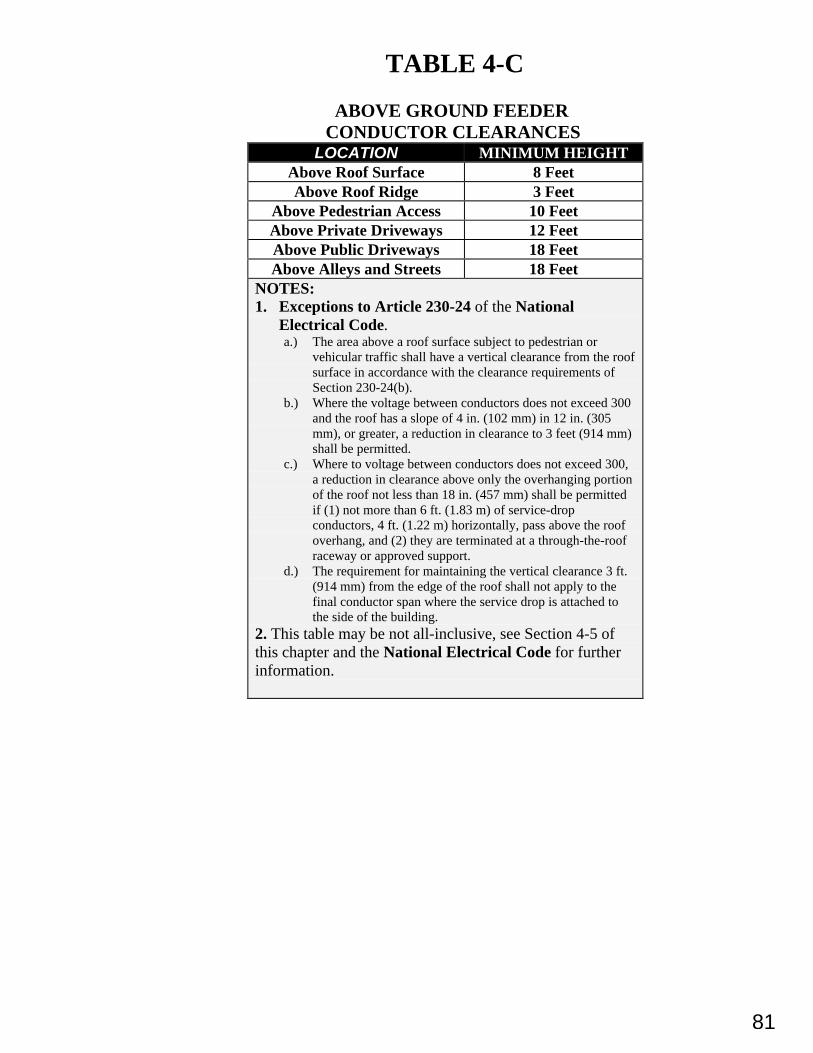
81
TABLE 4-C
ABOVE GROUND FEEDERCONDUCTOR CLEARANCES
LOCATION MINIMUM HEIGHTAbove Roof Surface 8 FeetAbove Roof Ridge 3 Feet
Above Pedestrian Access 10 FeetAbove Private Driveways 12 FeetAbove Public Driveways 18 FeetAbove Alleys and Streets 18 Feet
NOTES:1. Exceptions to Article 230-24 of the National
Electrical Code.a.) The area above a roof surface subject to pedestrian or
vehicular traffic shall have a vertical clearance from the roofsurface in accordance with the clearance requirements ofSection 230-24(b).
b.) Where the voltage between conductors does not exceed 300and the roof has a slope of 4 in. (102 mm) in 12 in. (305mm), or greater, a reduction in clearance to 3 feet (914 mm)shall be permitted.
c.) Where to voltage between conductors does not exceed 300,a reduction in clearance above only the overhanging portionof the roof not less than 18 in. (457 mm) shall be permittedif (1) not more than 6 ft. (1.83 m) of service-dropconductors, 4 ft. (1.22 m) horizontally, pass above the roofoverhang, and (2) they are terminated at a through-the-roofraceway or approved support.
d.) The requirement for maintaining the vertical clearance 3 ft.(914 mm) from the edge of the roof shall not apply to thefinal conductor span where the service drop is attached tothe side of the building.
2. This table may be not all-inclusive, see Section 4-5 ofthis chapter and the National Electrical Code for furtherinformation.
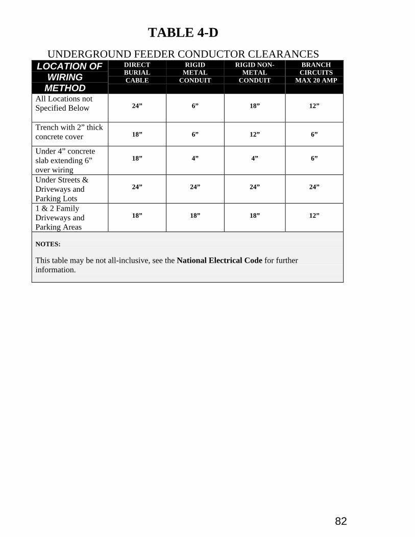
82
TABLE 4-D
UNDERGROUND FEEDER CONDUCTOR CLEARANCESLOCATION OF
WIRINGMETHOD
DIRECTBURIALCABLE
RIGIDMETAL
CONDUIT
RIGID NON-METAL
CONDUIT
BRANCHCIRCUITS
MAX 20 AMP
All Locations notSpecified Below 24” 6” 18” 12”
Trench with 2” thickconcrete cover 18” 6” 12” 6”
Under 4” concreteslab extending 6”over wiring
18” 4” 4” 6”
Under Streets &Driveways andParking Lots
24” 24” 24” 24”
1 & 2 FamilyDriveways andParking Areas
18” 18” 18” 12”
NOTES:
This table may be not all-inclusive, see the National Electrical Code for furtherinformation.
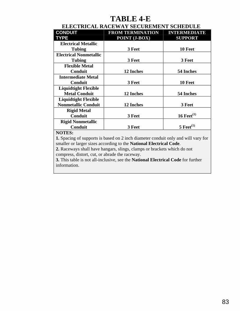
83
TABLE 4-E ELECTRICAL RACEWAY SECUREMENT SCHEDULECONDUITTYPE
FROM TERMINATIONPOINT (J-BOX)
INTERMEDIATESUPPORT
Electrical MetallicTubing 3 Feet 10 Feet
Electrical NonmetallicTubing 3 Feet 3 Feet
Flexible MetalConduit 12 Inches 54 Inches
Intermediate MetalConduit 3 Feet 10 Feet
Liquidtight FlexibleMetal Conduit 12 Inches 54 Inches
Liquidtight FlexibleNonmetallic Conduit 12 Inches 3 Feet
Rigid MetalConduit 3 Feet 16 Feet(1)
Rigid NonmetallicConduit 3 Feet 5 Feet(1)
NOTES:1. Spacing of supports is based on 2 inch diameter conduit only and will vary forsmaller or larger sizes according to the National Electrical Code.2. Raceways shall have hangars, slings, clamps or brackets which do notcompress, distort, cut, or abrade the raceway.3. This table is not all-inclusive, see the National Electrical Code for furtherinformation.
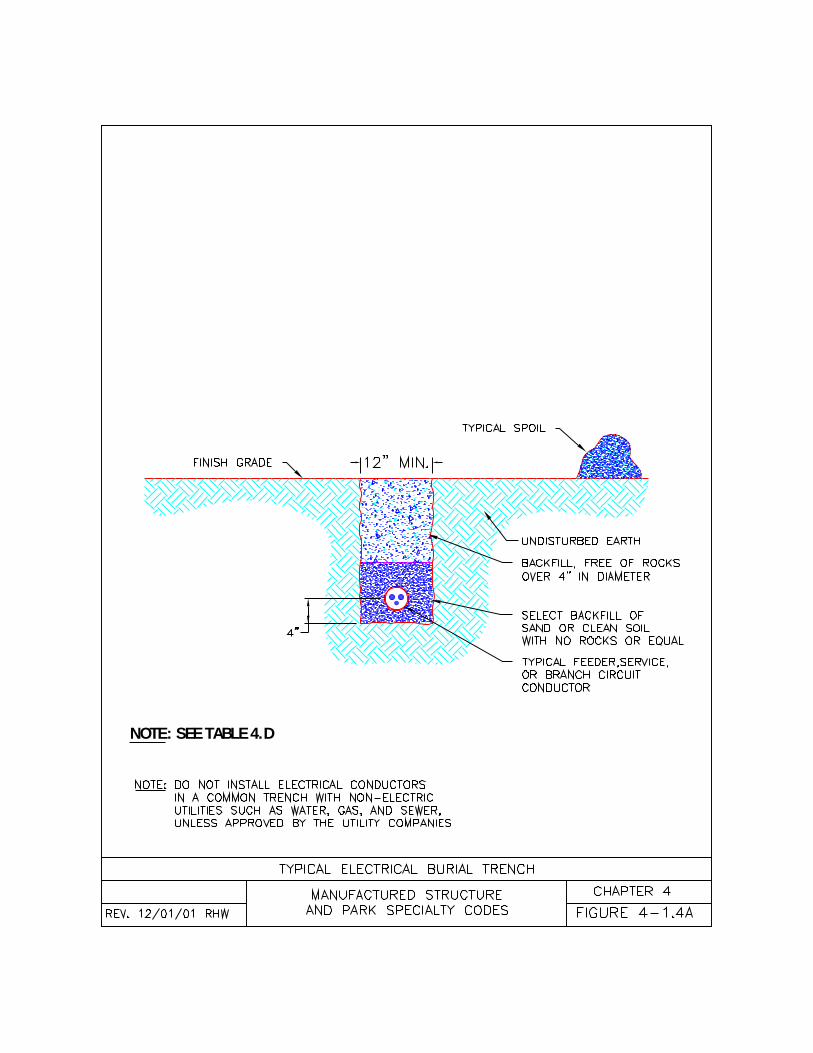
NOTE: SEE TABLE 4.D
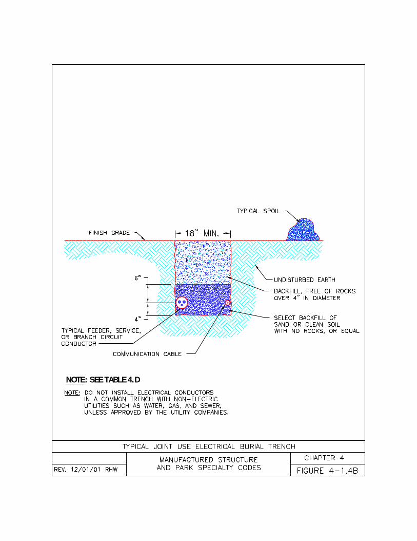
NOTE: SEE TABLE 4.D
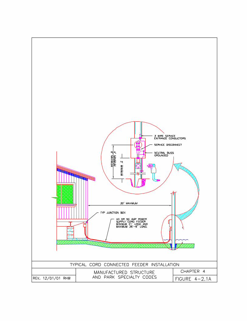
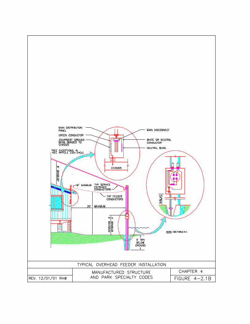
NOTE: SEE TABLE 4-C
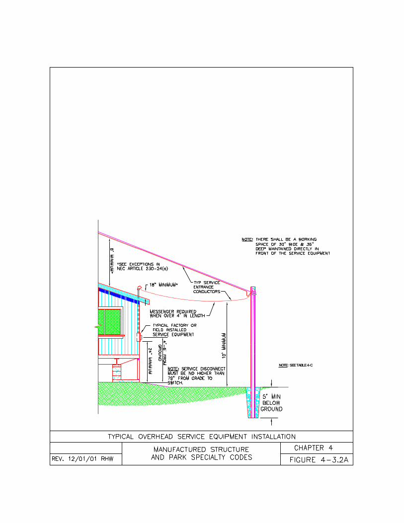
NOTE: SEE TABLE 4-C
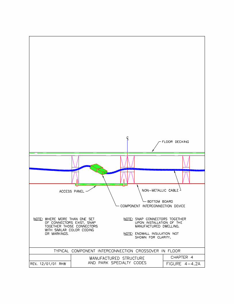
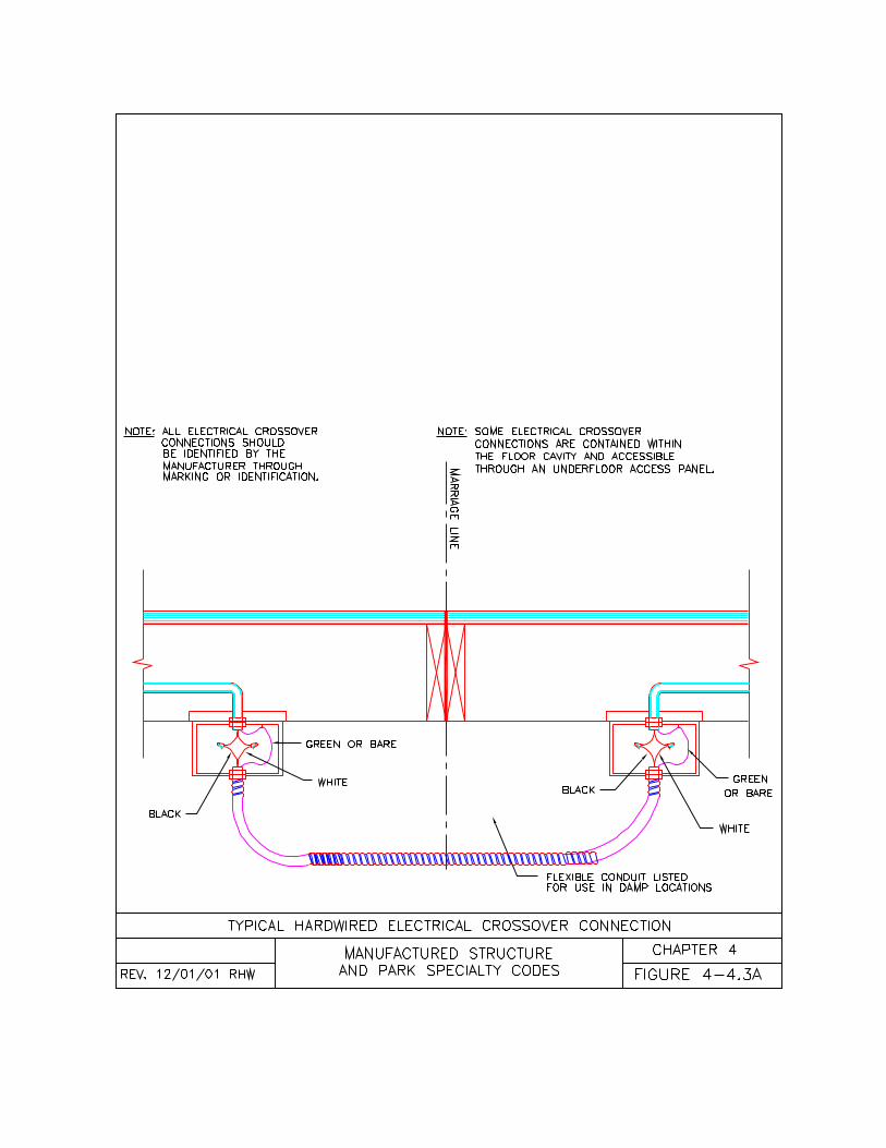
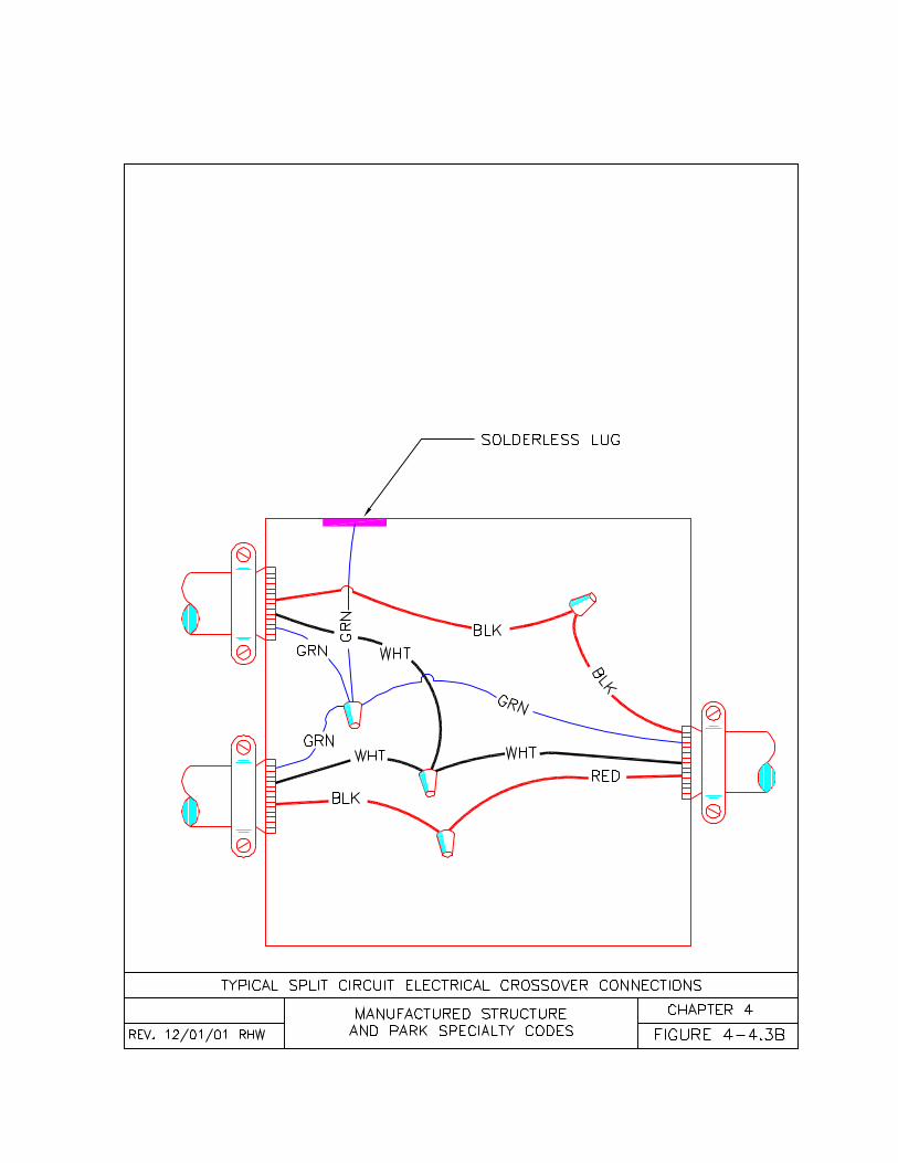
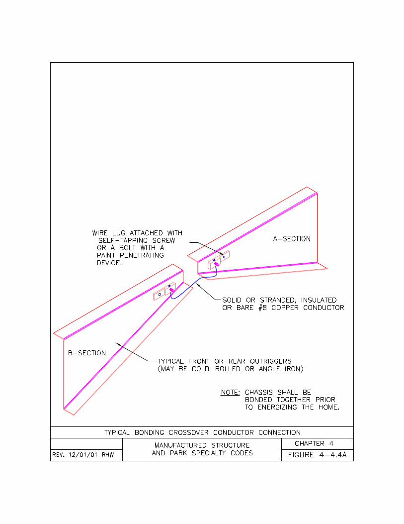
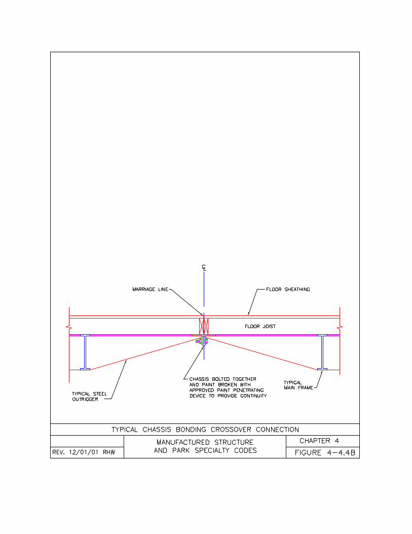
85
CHAPTER FIVEPLUMBING CONNECTIONS
5-1 General5-2 Water Installation Requirements5-3 Drain Installation Requirements5-4 Plumbing Tests
5-1 General5-1.1 Plumbing Installations. Thischapter of the code is intended tosupplement the plumbing requirements ofthe federal Manufactured HomeConstruction and Safety Standards 24CFR 3280, the Oregon One and TwoFamily Dwelling Specialty Code, andthe Oregon Plumbing Specialty Code,but is not intended to take the place ofthese codes.(a) Wherever the requirements of thiscode differ from the Oregon One andTwo Family Dwelling Specialty Code,or the Oregon Plumbing SpecialtyCode, this code shall apply;(b) Alternate methods permitted in theOregon One and Two Family DwellingSpecialty Code, or the OregonPlumbing Specialty Code but notmentioned in this code may be permittedif acceptable to the authority havingjurisdiction;(c) All plumbing fixtures, piping, andfittings shall be without defect. Alldamaged materials shall be discardedand replaced;(d) All plumbing installations under themanufactured dwelling shall be madeaccording to the Manufactured HomeConstruction and Safety Standards 24CFR 3280, and, where not specific, to thiscode or to the material manufacturer’sinstallation instructions;(e) All plumbing installation methodsoutside the manufactured dwelling under-floor area shall be according to thematerial manufacturer’s installationinstructions, this chapter, and, where notspecific, to the Oregon One and TwoFamily Dwelling Specialty Code;
(f) All plumbing fixtures and equipmentused in conjunction with the installation,alteration, or conversion of amanufactured dwelling shall be approvedaccording to Table 5-A of this code, or,where not specific, to the Oregon Oneand Two Family Dwelling SpecialtyCode; and(g) All plumbing materials (i.e. pipe,fittings, fixtures, equipment, and devices)shall be approved and marked or labeledfor the intended use according to thiscode or, where not specific, to either theManufactured Home Construction andSafety Standards 24 CFR 3280, theOregon One and Two Family DwellingSpecialty Code, or the OregonPlumbing Specialty Code.
5-1.2 Manufactured DwellingInstallations. Plumbing installations andconnections made during the installationof a manufactured dwelling shall complywith the following:(a) Plumbing located under themanufactured dwelling shall be plumbedaccording to the federal ManufacturedHome Construction and SafetyStandards, 24 CFR Subpart G, and,where not specific, to this code; or(b) Plumbing located outside themanufactured dwelling under-floorenclosure shall be plumbed according tothis code and, where not specific, to theOregon One and Two Family DwellingSpecialty Code; and(c) When a manufactured dwelling islocated in a flood hazard area, allplumbing openings shall be located aminimum of 12 inches (30 cm) above thebase flood elevation or be equipped withapproved backwater valves.
5-1.3 Underground Installations.Piping installed deeper than and parallelto footings shall be set away from thefooting at a minimum of 45 degrees (seeFigure 5-1.4A). Piping shall be installedin trenches so that it rests on a solid andcontinuous bearing surface. When overexcavated, the trench shall be back filled
86
to the proper grade with compacted earth,sand, fine gravel, or equal. Piping shallnot be supported on rocks or blocks atany point. Where the building drain orbuilding sewer is made of the approvedmaterials shown in Table 5-E or Table 5-F of this code, the water and sewer pipingmay be laid in the same trench. If thebuilding drain or building sewer is notmade of the approved materials shown inTable 5-E or Table 5-F of this code, thewater piping shall be placed on a solidledge a minimum of 12 inches (30 cm)above the building drain or building sewer(see Figure 5-1.4B). Rocky or unstablesoil shall be excavated to a depth greaterby two or more pipe diameters andbrought to the proper grade with suitablecompacted granular material. Backfilltrenches with clean soil free from rocks,broken concrete, and other rubble.
5-1.4 Alterations, Additions andRepairs. All plumbing installations inconnection with alterations, additions,repairs, re-manufacturing, or refurbishingof a manufactured dwelling before or atthe time of sale to the first consumer shallcomply with the Manufactured HomeConstruction and Safety Standards 24CFR 3280, and, where not specific, withthis code and the Oregon One and TwoFamily Dwelling Specialty Code.
5-1.5 Manufactured DwellingConversions. All plumbing installationsin connection with a manufactureddwelling conversion or change ofoccupancy to a non-residential use shallbe made according to the OregonPlumbing Specialty Code.
5-1.6 Basements and Cabanas. Allplumbing installations in basements andcabanas shall be made according to theOregon One and Two Family DwellingSpecialty Code. Cabana plumbing maybe connected directly to themanufactured dwelling’s water and drainlines, provided they are sized toadequately handle the additional demand.
5-1.7 Plumbing Assembly. All plumbingshall be assembled according to thefollowing:(a) Plumbing assemblies shall be freefrom defect, demonstrate acceptableworkmanship, and be installed inconformance with acceptable engineeringpractices and this code;(b) Piping shall be installed according tothe manufacturer’s installationinstructions using approved componentparts;(c) Threaded pipe ends shall be reamedout to the size of the bore and all burrs,chips, cutting oil and foreign matterremoved;(d) Pipe threads and slip joints shall notbe wrapped with string, paper, putty, orsimilar fillers;(e) Pipe joint compound used on waterpipes shall be nontoxic and shall beapplied to male threads only;(f) Pipe threads shall be fully engagedinto the threads of the fitting;(g) Pipe joint cement shall be of approvedtype and applied to both pipe and fitting ofslip joint connections;(h) Plastic pipe shall be inserted to the fulldepth of the welding sockets of eachfitting;(i) Joints and connections in the plumbingsystem shall be gas-tight and watertightunder normal operating pressures;(j) All joints and connections shall becorrectly assembled for tightness;(k) Piping shall be installed without unduestrains and stresses;(l) Piping shall have provisions forexpansion, contraction, and structuralsettlement;(m) Piping shall have supports ofsufficient strength to keep the piping inalignment and carry the weight of thepiping and its contents. Supports mayhang down from the bottom of themanufactured dwelling floor or mayconsist of blocking from the ground up;(n) All horizontal piping shall besupported according to Table 5-B; pipingsupport does not require upward verticalrigid support.
87
(o) Piping shall have hangers, clamps,brackets, blocking, or anchors that do notcompress, distort, cut or abrade the waterpipe;1. Sheet metal or plastic plumbers tapemay be used to support metallic waterlines; or2. Plastic plumbers tape or equal may beused to support plastic water lines.(p) Piping penetrations through concreteslabs or footings shall be sleeved sothere is ½” clearance around the pipe.The piping shall not be subject to anyload from the building construction. Eachpenetration shall be caulked around thepipe (see Figures 5-2.1B and 5-3.1); and(q) Plumbing shall not obstruct the under-floor access area.
5-1.8 Inspection. All plumbing work shallbe accessible for inspections. Allexcavations containing plumbing shall beleft open for inspection by the authorityhaving jurisdiction.
5-2 Water Installation Requirements5-2.1 Water Connections. Theinstallation and connection ofmanufactured dwelling water distributionsystem (utility connection) to the buildingwater supply (utility termination) shallcomply with the following:(a) The building water supply piping shallbe new and made of approved materialslisted in Table 5-C of this code;(b) The building water supply shall be aminimum ¾ inches (2 cm) inside diameterbased on 12 fixture units as identified inTable 6-5 of the Oregon PlumbingSpecialty Code. Where the buildingwater supply exceeds 100 lineal feet, thebuilding water supply shall be sizedaccording to Table 5-D of this code.Where plumbing fixtures are added onsite, see Section 5-2.5 of this chapter forthe correct sizing;(c) The installation and connection by theMDI (Licensed Manufactured DwellingInstaller) of the manufactured dwellingwater distribution system to the buildingwater supply provided on a lot shallconsist of not more than 30 lineal feet
(914 cm) of pipe and fittings starting fromthe exterior of the manufactured dwelling;(d) When a backflow device (check valve)is installed in the building water supply,an approved thermal expansion tank orother device designed for intermittentoperation for thermal expansion controlshall be installed according to themanufacturer’s installation instructions;(e) Expansion tanks shall be adequatelysupported to carry twice the weight of thetank filled with water without placing anystrain on the connecting piping;(f) An accessible full way shutoff valveshall be installed under or within 5 feet(152 cm) of the manufactured dwelling onthe building water supply serving themanufactured dwelling (see Figure 5-2.1B). The valve on the water meter maynot serve as the shutoff valve for themanufactured dwelling;(g) The water distribution system shall beconnected to the building water supplyunder the manufactured dwelling with anapproved connector as listed in Table 5-C. The piping connections shall not besubjected to any loads from the buildingstructure;(h) Where static water pressure exceeds80 pounds per square inch (552 KPa) atthe building water supply connection tothe manufactured dwelling waterdistribution system, an approved pressureregulator shall be installed;(i) There shall be no cross connectionbetween potable and non-potable water;
5-2.2 Protection. Water fixtures, piping,and devices shall be protected accordingto the following requirements:(a) Water heaters shall be equipped withpressure relief valves and drain pipes thatterminate and discharge beneathmanufactured dwellings;(b) Pressure relief valve drain pipes shallnot be trapped, tapped, threaded,capped, plugged, altered, diverted, orextended;(c) The building water supply piping,water distribution system inlet, expansiontank, when required, and main shut offvalve located under the manufactured
88
dwelling shall be protected from freezingwith pipe insulation or with the installationof a electric heat tape listed and approvedfor manufactured home use;
5-2.3 Marriage Line WaterConnections. The water line crossoverson multi-section manufactured dwellingsshall be connected according to thefollowing (see Figure 5-2.3A and 5-2.3B):(a) With the connectors supplied by themanufacturer; or(b) With an approved flexible waterconnector sized no less than the waterlines being connected or with otherapproved materials listed in Table 5-C ofthis code; and(c) Exposed water line crossoverconnections shall be protected fromfreezing with pipe insulation or with theinstallation of an approved electric heattape listed for use with manufacturedhomes.
5-2.4 Underground Installations. Inaddition to those requirements in Section5-1.4 of this chapter, building watersupply piping shall be installed intrenches according to the following:(a) No portion of the building water supplypipe shall be installed above groundoutside the manufactured dwelling’sunder-floor enclosure except as approvedby the local jurisdiction;(b) Piping in a trench must be supportedon a continuous bed of approved material(see Figures 5-1.4A and 5-1.4B);(c) Building water supply piping shall beburied a minimum of 18 inches (46 cm)below grade and at least 12 inches (30cm) below the frost line (see Figure 5-2.1B); and(d) All non-metallic water piping laid in atrench to be covered shall have a tracerwire installed to the followingrequirements (see Figure 5-2.1B):1. Tracer wire shall be blue 18 gaugeinsulated copper electrically conductivewire or greater;
2. Tracer wire shall be installed in thetrench along the entire length of the pipe;and3. Each end of the tracer wire shall be leftabove the finished grade and be clearlymarked, one end shall be at themanufactured dwelling connection andthe other terminated in the meter box,well head, or reservoir tank.
5-2.5 Accessories. All plumbinginstallations in connection with anaccessory building, accessory structure,or other external systems (i.e. basement,cabana, shed, garage, hose bibbs, patiosinks, and sprinkler systems) shall bemade according to this code and, wherenot specific, to the Oregon One and TwoFamily Dwelling Specialty Code:(a) External plumbing systems may beconnected directly to the manufactureddwelling’s water supply inlet provided thediameter of the water supply piping to themanufactured dwelling is increased whennecessary to adequately handle theadditional demand according to Table 6-4and Table 6-5 of the Oregon PlumbingSpecialty Code;(b) When external water systems (i.e.hose bibbs, sprinkler systems, oraccessory building fixtures) are added atthe water inlet of the manufactureddwelling, an approved back flowprevention device shall be installedbetween the building supply connectionand the external fixtures or system;(c) Hose bibbs installed through anuninsulated under-floor enclosure shall beequipped with an accessible stop-and-waste-type valve inside the under-floorarea (crawl space) of the manufactureddwelling so that they are capable of beingcontrolled and/or drained during freezingweather;(d) Hose bibbs installed into an insulatedfloor or wall cavity shall be frost proof butare not required to have the stop-and-waste-type valves installed.
5-2.6 Main Water Valve Access. Themain water valve shall be accessible fromthe exterior of the manufactured dwelling
89
according to the following (see Figure 5-2.1B):(a) Water valves located under themanufactured dwelling shall beaccessible through a minimum 6 inch by6 inch (15 cm by 15 cm) hand holethrough the under-floor enclosure(foundation wall or skirting) within reachand not more than 12 inches (30 cm)from the access opening; or(b) Water valves located outside themanufactured dwelling under-floorenclosure, shall be below ground andinside a vault having a minimum 7 inches(18 cm) diameter opening or equal at orabove ground level.
5-2.7 Access. The following access shallbe provided to the manufactured dwellingwater distribution system piping andconnections:(a) Water crossover connections shall beaccessible, but may be covered withinsulation and/or an access panel; and(b) All access panels in walls and floorsshall be insulated and secured in placeafter all plumbing tests are complete (seeFigure 5-2.3B).
5-3 Drain Installation Requirements5-3.1 Sewer/Drain Connection. Theinstallation and connection of themanufactured dwelling drain outlet, to thebuilding drain (utility connection), buildingsewer (utility termination) shall complywith the following:(a) The building drain piping shall bemade of approved materials as listed inTable 5-E of this code;(b) The building sewer piping shall bemade of approved materials as listed inTable 5-F of this code;(c) The building drain and building sewershall be a minimum of 3 inches (76 mm)inside diameter based on 12 fixture unitsas identified in Table 7-3 of the OregonPlumbing Specialty Code;(d) The installation and connection by theMDI (Licensed Manufactured DwellingInstaller) of the manufactured dwellingbuilding drain to the building sewerprovided on a lot shall consist of not more
than 30 lineal feet (914 cm) of pipe andfittings from the exterior of themanufactured dwelling;(e) Each manufactured dwelling shallhave only one drain outlet; and(f) Each manufactured dwelling shall beconnected to the building sewer bymeans of a building drain connectorconsisting of approved piping not lessthan schedule 40, no smaller than themanufactured dwelling drain outlet or aminimum of 3 inches (8 cm) in diameter.Listed and approved shielded flexibleconnectors may be used to join thedrainpipe to the sewer inlet (see Figure5.3.1).
5-3.2 Drainage Piping. Building drainand building sewer piping shall complywith the following:(a) Piping shall be semi-rigid, durable,corrosion resistant, non-absorbent, andhave a smooth interior surface;(b) Piping shall be installed according tothe manufacturer’s installationinstructions using the component partssupplied or required by the manufacturer;(c) Piping shall be installed to provide a1/4 inch (6 mm) per foot (305 meters)grade in all horizontal drain piping. Whena full size cleanout is installed at theupper end, the grade may be reduced to1/8 inch (3 mm) per foot (305 mm);(d) Piping shall use appropriate approvedfittings for all changes in direction:1. For all horizontal to vertical drain pipeconnections, use 45 degree “Y” branches,60 degree “Y” branches, long-turn “TY”branches, sanitary “T” branches or otherapproved fittings, or combination offittings having equivalent sweep; and2. For all horizontal to horizontal andvertical to horizontal drainpipeconnections, use 45 degree “Y” branches,long-turn “TY” branches, or otherapproved fittings or combination of fittingshaving equivalent sweep.(e) Piping shall be installed without unduestrains and stresses;(f) Piping shall have provisions forexpansion, contraction, and structuralsettlement;
90
(g) Piping shall be supported and securedaccording to Table 5-B (see Figures 5-3.2 and 5-3.4). Piping support does notrequire upward vertical rigid support;(h) Piping shall have supports sufficient tokeep the pipe in alignment and carry theweight of the pipe and its contents.Supports may hang down from thebottom of the manufactured dwelling flooror may consist of blocking from theground up attached in place with bracketsor plumbers tape (see Figures 5-3.2 and5-3.4);(i) Piping shall have hangers, slings,blocking, clamps, or brackets which donot compress, distort, cut or abrade thedrainpipe. Sheet metal straps or plumberstape may be used for support of plasticdrain lines as long as the strap is flatagainst the drain pipe (see Figures 5-3.2and 5-3.4); and(j) Piping shall have cleanouts providedaccording to the following:1. Cleanouts shall be located so acleaning tool does not have to passthrough more than 360 degrees of fittings,excluding removable “P” traps;2. Cleanout fittings shall be installed sothey allow for cleaning in the direction ofthe flow or at right angles to the pipe; and3. Cleanouts shall not be less in diameterthan the pipes they are being connectedto.
5-3.3 Sewer Cleanout Access. A maindrain cleanout fitting shall be installed inthe building drain under or within 5 feet(152 cm) of the manufactured dwellingaccording to the following requirements(see Figure 5-3.1):(a) The main drain cleanout shall bemade with a directional fitting aboveground or a two-way cleanout fitting ifunderground;(b) The main drain cleanout shall have 18inch (46 cm) of clearance directly in frontof the cleanout opening without removingany permanent construction;(c) The main drain cleanout shall havethe same diameter as the largest drainpipe contained in the building drain; and
(d) The main drain cleanout shall beaccessible from the exterior of themanufactured dwelling according to thefollowing (see Figure 5-3.1):1. Main drain cleanouts located under themanufactured dwelling shall beaccessible through a minimum 6 inch by6 inch (15 cm by 15 cm) hand holethrough the under-floor enclosure(foundation wall or skirting) within reachand not more than 12 inches (30 cm)from the access opening; or2. Main drain cleanouts located outsidethe manufactured dwelling under-floorenclosure, shall be below ground andinside a vault having a minimum 11 inch(28 cm) diameter opening or equal, at orabove ground level.
5-3.4 Marriage Line Drain Connections.The drain line crossovers on multi-sectionmanufactured dwellings shall beconnected according to one the following(see Figure 5-3.4):(a) With the connectors supplied by themanufacturer;(b) With approved pipe and fittings (seeTable 5-E) not less than schedule 40 andof the same diameter as the pipes beingconnected; or(c) With approved shielded flexibleconnectors.
5-3.5 Underground Installations. Inaddition to those requirements in Section5-1.4 of this chapter, building drain andbuilding sewer piping installed in trenchesshall conform to the following:(a) No portion of the building drain orbuilding sewer pipe shall be installedabove ground outside the manufactureddwelling’s under-floor enclosure;(b) Building drain and building sewerpiping in a trench must be supported on acontinuous bed of approved material (seeFigures 5-1.4A and 5-1.4B);(c) All building drain and building sewerpipe shall be graded at 1/4 inch (6 mm)per foot (30 cm) except as otherwisepermitted by the authority havingjurisdiction; and
91
(d) All nonmetallic building drain andbuilding sewer pipe laid in a trench to becovered shall have a tracer wire installedto the following requirements (see Figure5-3.1):1. It shall be green, 18 gauge, insulated,electrically conductive wire or greater;2. It shall be installed in the trench alongthe entire length of the pipe; and3. One end of the tracer wire shall be leftabove the finished grade at the cleanoutnext to the manufactured dwelling.
5-3.6 Ship-Loose Drain Lines.Manufactured dwelling under-floordrainage systems may be shipped by themanufacturer by one of the followingmethods:(a) Complete and ready to be connectedto the site building drain;(b) Loose in one or more pre-assembledsections to be attached with unions andthen connected to the site building drain;(c) Loose sections intended for siteassembly as approved by the DAPIA andprovided with all pipe, fittings, cement,supports and DAPIA approvedmanufacturer's instructions necessary forproper site installation; or(d) Loose with no pre-assembledsections, supports, or instructions,requiring extensive plumbing design andwork on site.
5-3.7 Accessories. All plumbinginstallations in connection with anaccessory building, accessory structure,or other external systems (i.e. basement,cabana, shed, garage, hose bibbs, patiosinks, and sprinkler systems) shall bemade according to this code and, wherenot specific, to the Oregon One and TwoFamily Dwelling Specialty Code:(a) External systems may be connecteddirectly to the manufactured dwelling’sbuilding drain provided the diameter ofthe building drain is increased whennecessary to adequately handle theadditional demand according to Table 7-3of the Oregon Plumbing SpecialtyCode;
(b) When external water systems areadded, an approved backflow preventiondevice shall be installed between thebuilding supply connection and theexternal fixture or system; and (c) When roof additions or ramadas areinstalled on or over a manufactureddwelling, the manufactured dwelling’splumbing vents shall be extended at least6 inches (15 cm) above the new roof andproperly flashed.
5-3.8 Access and Clearances. Thefollowing accesses and clearances shallbe provided for manufactured dwellingdrainage system:(a) There shall be an unobstructedminimum clearance of 18 inches (46 cm)directly in front of each cleanout opening;(b) Concealed cleanouts inside a floor orwall shall be accessible through accesspanels;(c) Traps with mechanical joints locatedinside a floor or wall shall be accessiblethrough an access panel;(d) Drain cross-over connections shall beaccessible; and(e) All access panels in walls and floorsshall be insulated and secured in placeafter all plumbing tests are complete.
5-4 Plumbing Tests5-4.1 Water Test. Upon completion of thebuilding water supply connection,marriage line crossover connections, andall additional accessory plumbingconnections, the person making the watersupply connection shall test themanufactured dwelling water distributionsystem to assure there is no evidence ofleakage under normal operating pressureaccording to the following:(a) Pressurize all water lines from thesite’s water supply;1. If water under normal operatingpressure is not available, themanufactured dwelling water distributionsystem shall be pressurized with aminimum of 80 pounds per square inch(552 KPa) of air pressure. If the waterlines are made of CPVC, reduce pressure
92
test to 30 pounds per square inch (206.7KPa);2. Record the pressure at the beginningof the test and hold at that pressure for 15minutes; and3. After 15 minutes of pressure testing,check the pressure gauge to assure therehas been no drop in pressure.(b) After the water lines are full of water,check the building water supplyconnection, marriage line crossoverconnections, and each fixture connectionfor leaks.
5-4.2 Drain Test. Upon completion of thebuilding drain connection to the buildingsewer, the marriage line crossoverconnections, and any additionalaccessory drainage connections, theperson making the drain connection shalltest the manufactured dwelling drainagesystem to assure there is no evidence ofleakage under normal operatingconditions according to the following:(a). Remove all access panels to all P-traps, cleanout, and fixture drainconnections inside the walls and floor;(b) Test each fixture or receptor, includingthe clothes washer standpipe, for aminimum of 3 minutes by letting waterflow at the normal operating pressure. Ifwater under pressure is not available, testeach fixture and receptor by pouring atleast 3 gallons (11 liters) of water intoeach fixture and receptor;(c) Visually check each P-trap, cleanout,and fixture or receptor connection forleaks during the test; and(d) After the test has been successfullycompleted, replace all insulation andaccess panels in floors and walls.
NOTE: Inspectors have the authority towitness each test but are not obligated todo so.
5-4.3 Test Failures. Upon failure of anyof the above tests, check all applicablefield connections, correct any leaks, andrepeat the applicable test. If testscontinue to fail, notify factory authorizedservice personnel immediately and report
failures. Other than during testing, do notturn on the water supply to themanufactured dwelling until all leaks havebeen repaired.
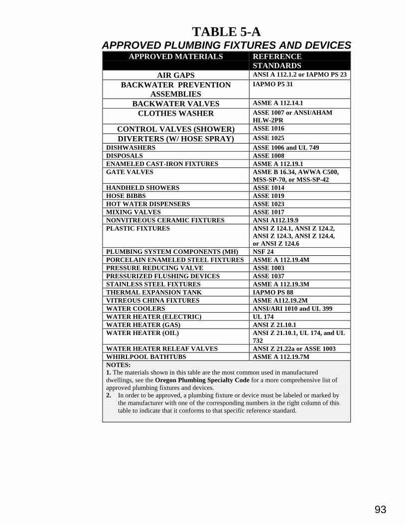
93
TABLE 5-AAPPROVED PLUMBING FIXTURES AND DEVICES
APPROVED MATERIALS REFERENCESTANDARDS
AIR GAPS ANSI A 112.1.2 or IAPMO PS 23
BACKWATER PREVENTIONASSEMBLIES
IAPMO P5 31
BACKWATER VALVES ASME A 112.14.1
CLOTHES WASHER ASSE 1007 or ANSI/AHAMHLW-2PR
CONTROL VALVES (SHOWER) ASSE 1016
DIVERTERS (W/ HOSE SPRAY) ASSE 1025
DISHWASHERS ASSE 1006 and UL 749DISPOSALS ASSE 1008ENAMELED CAST-IRON FIXTURES ASME A 112.19.1GATE VALVES ASME B 16.34, AWWA C500,
MSS-SP-70, or MSS-SP-42HANDHELD SHOWERS ASSE 1014HOSE BIBBS ASSE 1019HOT WATER DISPENSERS ASSE 1023MIXING VALVES ASSE 1017NONVITREOUS CERAMIC FIXTURES ANSI A112.19.9PLASTIC FIXTURES ANSI Z 124.1, ANSI Z 124.2,
ANSI Z 124.3, ANSI Z 124.4,or ANSI Z 124.6
PLUMBING SYSTEM COMPONENTS (MH) NSF 24PORCELAIN ENAMELED STEEL FIXTURES ASME A 112.19.4MPRESSURE REDUCING VALVE ASSE 1003PRESSURIZED FLUSHING DEVICES ASSE 1037STAINLESS STEEL FIXTURES ASME A 112.19.3MTHERMAL EXPANSION TANK IAPMO PS 88VITREOUS CHINA FIXTURES ASME A112.19.2MWATER COOLERS ANSI/ARI 1010 and UL 399WATER HEATER (ELECTRIC) UL 174WATER HEATER (GAS) ANSI Z 21.10.1WATER HEATER (OIL) ANSI Z 21.10.1, UL 174, and UL
732WATER HEATER RELEAF VALVES ANSI Z 21.22a or ASSE 1003WHIRLPOOL BATHTUBS ASME A 112.19.7MNOTES:1. The materials shown in this table are the most common used in manufactureddwellings, see the Oregon Plumbing Specialty Code for a more comprehensive list ofapproved plumbing fixtures and devices.2. In order to be approved, a plumbing fixture or device must be labeled or marked by
the manufacturer with one of the corresponding numbers in the right column of thistable to indicate that it conforms to that specific reference standard.
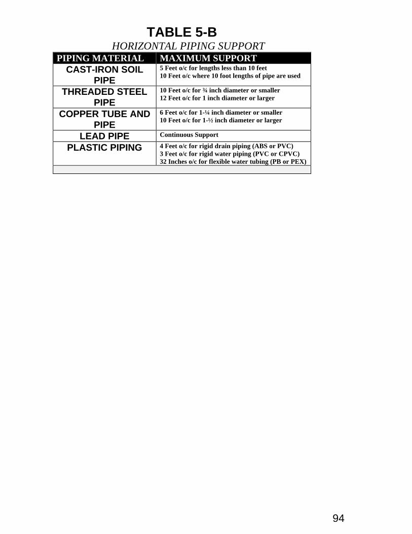
94
TABLE 5-B HORIZONTAL PIPING SUPPORT
PIPING MATERIAL MAXIMUM SUPPORTCAST-IRON SOIL
PIPE
5 Feet o/c for lengths less than 10 feet10 Feet o/c where 10 foot lengths of pipe are used
THREADED STEELPIPE
10 Feet o/c for ¾ inch diameter or smaller12 Feet o/c for 1 inch diameter or larger
COPPER TUBE ANDPIPE
6 Feet o/c for 1-¼ inch diameter or smaller10 Feet o/c for 1-½ inch diameter or larger
LEAD PIPE Continuous Support
PLASTIC PIPING 4 Feet o/c for rigid drain piping (ABS or PVC)3 Feet o/c for rigid water piping (PVC or CPVC)32 Inches o/c for flexible water tubing (PB or PEX)
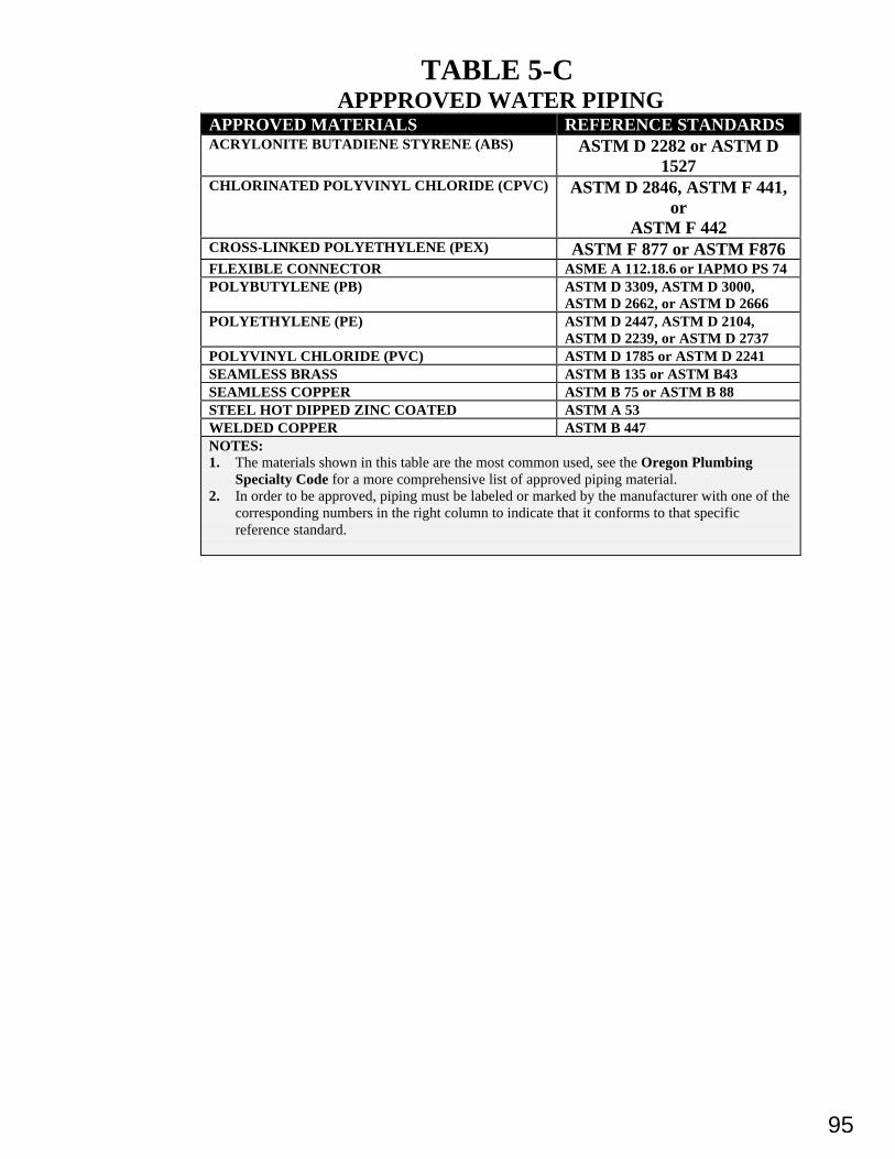
95
TABLE 5-CAPPPROVED WATER PIPING
APPROVED MATERIALS REFERENCE STANDARDSACRYLONITE BUTADIENE STYRENE (ABS) ASTM D 2282 or ASTM D
1527CHLORINATED POLYVINYL CHLORIDE (CPVC) ASTM D 2846, ASTM F 441,
orASTM F 442
CROSS-LINKED POLYETHYLENE (PEX) ASTM F 877 or ASTM F876FLEXIBLE CONNECTOR ASME A 112.18.6 or IAPMO PS 74POLYBUTYLENE (PB) ASTM D 3309, ASTM D 3000,
ASTM D 2662, or ASTM D 2666POLYETHYLENE (PE) ASTM D 2447, ASTM D 2104,
ASTM D 2239, or ASTM D 2737POLYVINYL CHLORIDE (PVC) ASTM D 1785 or ASTM D 2241SEAMLESS BRASS ASTM B 135 or ASTM B43SEAMLESS COPPER ASTM B 75 or ASTM B 88STEEL HOT DIPPED ZINC COATED ASTM A 53WELDED COPPER ASTM B 447NOTES:1. The materials shown in this table are the most common used, see the Oregon Plumbing
Specialty Code for a more comprehensive list of approved piping material.2. In order to be approved, piping must be labeled or marked by the manufacturer with one of the
corresponding numbers in the right column to indicate that it conforms to that specificreference standard.
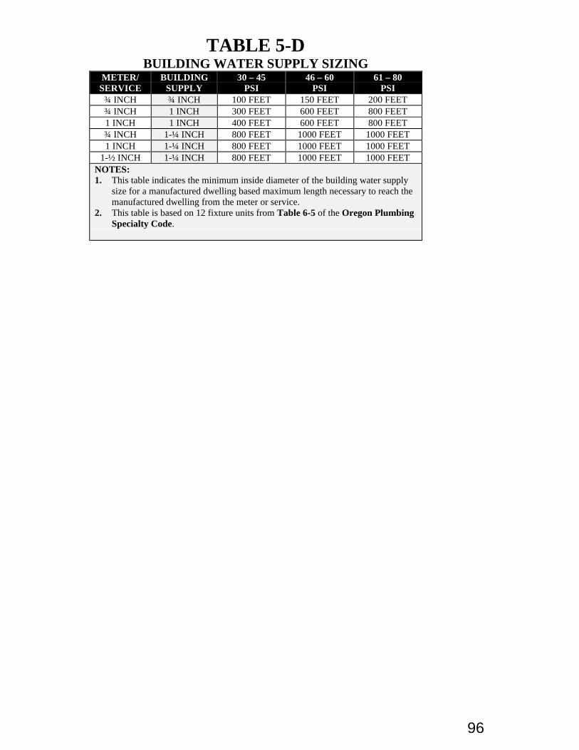
96
TABLE 5-DBUILDING WATER SUPPLY SIZING
METER/SERVICE
BUILDINGSUPPLY
30 – 45PSI
46 – 60PSI
61 – 80PSI
¾ INCH ¾ INCH 100 FEET 150 FEET 200 FEET¾ INCH 1 INCH 300 FEET 600 FEET 800 FEET1 INCH 1 INCH 400 FEET 600 FEET 800 FEET¾ INCH 1-¼ INCH 800 FEET 1000 FEET 1000 FEET1 INCH 1-¼ INCH 800 FEET 1000 FEET 1000 FEET
1-½ INCH 1-¼ INCH 800 FEET 1000 FEET 1000 FEETNOTES:1. This table indicates the minimum inside diameter of the building water supply
size for a manufactured dwelling based maximum length necessary to reach themanufactured dwelling from the meter or service.
2. This table is based on 12 fixture units from Table 6-5 of the Oregon PlumbingSpecialty Code.
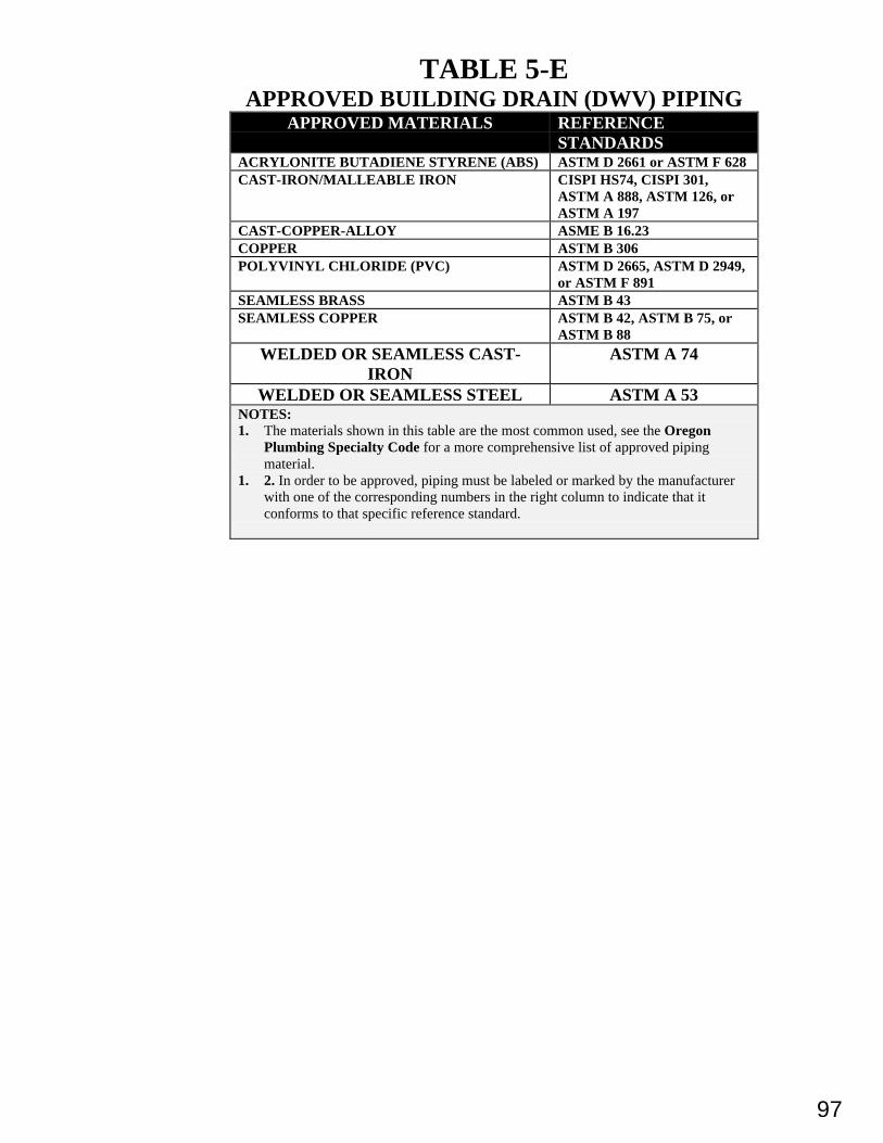
97
TABLE 5-EAPPROVED BUILDING DRAIN (DWV) PIPING
APPROVED MATERIALS REFERENCESTANDARDS
ACRYLONITE BUTADIENE STYRENE (ABS) ASTM D 2661 or ASTM F 628CAST-IRON/MALLEABLE IRON CISPI HS74, CISPI 301,
ASTM A 888, ASTM 126, orASTM A 197
CAST-COPPER-ALLOY ASME B 16.23COPPER ASTM B 306POLYVINYL CHLORIDE (PVC) ASTM D 2665, ASTM D 2949,
or ASTM F 891SEAMLESS BRASS ASTM B 43SEAMLESS COPPER ASTM B 42, ASTM B 75, or
ASTM B 88
WELDED OR SEAMLESS CAST-IRON
ASTM A 74
WELDED OR SEAMLESS STEEL ASTM A 53NOTES:1. The materials shown in this table are the most common used, see the Oregon
Plumbing Specialty Code for a more comprehensive list of approved pipingmaterial.
1. 2. In order to be approved, piping must be labeled or marked by the manufacturerwith one of the corresponding numbers in the right column to indicate that itconforms to that specific reference standard.
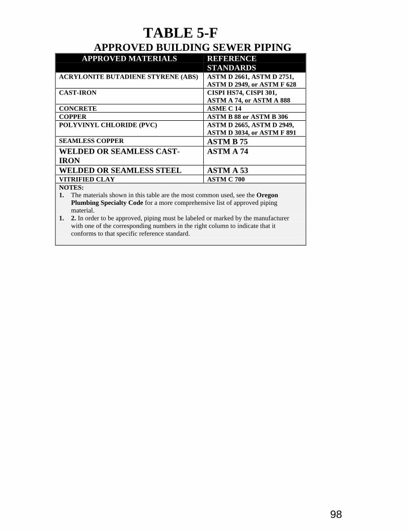
98
TABLE 5-FAPPROVED BUILDING SEWER PIPING
APPROVED MATERIALS REFERENCESTANDARDS
ACRYLONITE BUTADIENE STYRENE (ABS) ASTM D 2661, ASTM D 2751,ASTM D 2949, or ASTM F 628
CAST-IRON CISPI HS74, CISPI 301,ASTM A 74, or ASTM A 888
CONCRETE ASME C 14COPPER ASTM B 88 or ASTM B 306POLYVINYL CHLORIDE (PVC) ASTM D 2665, ASTM D 2949,
ASTM D 3034, or ASTM F 891SEAMLESS COPPER ASTM B 75WELDED OR SEAMLESS CAST-IRON
ASTM A 74
WELDED OR SEAMLESS STEEL ASTM A 53VITRIFIED CLAY ASTM C 700NOTES:1. The materials shown in this table are the most common used, see the Oregon
Plumbing Specialty Code for a more comprehensive list of approved pipingmaterial.
1. 2. In order to be approved, piping must be labeled or marked by the manufacturerwith one of the corresponding numbers in the right column to indicate that itconforms to that specific reference standard.
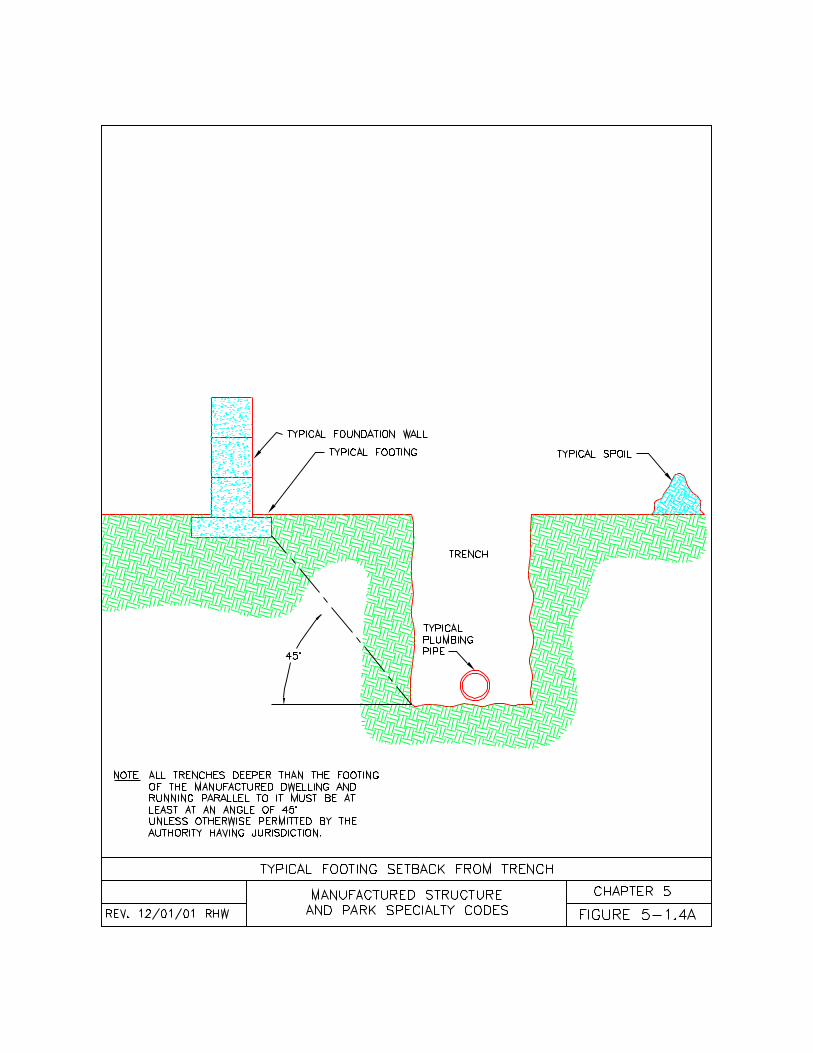
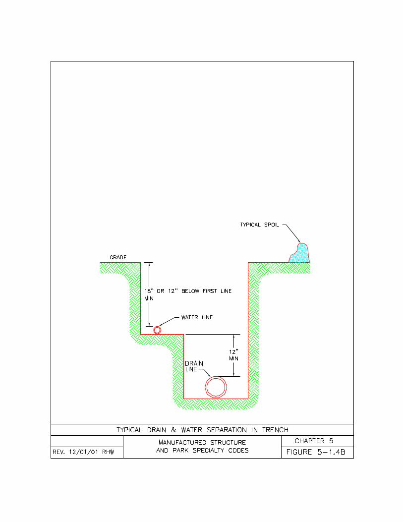
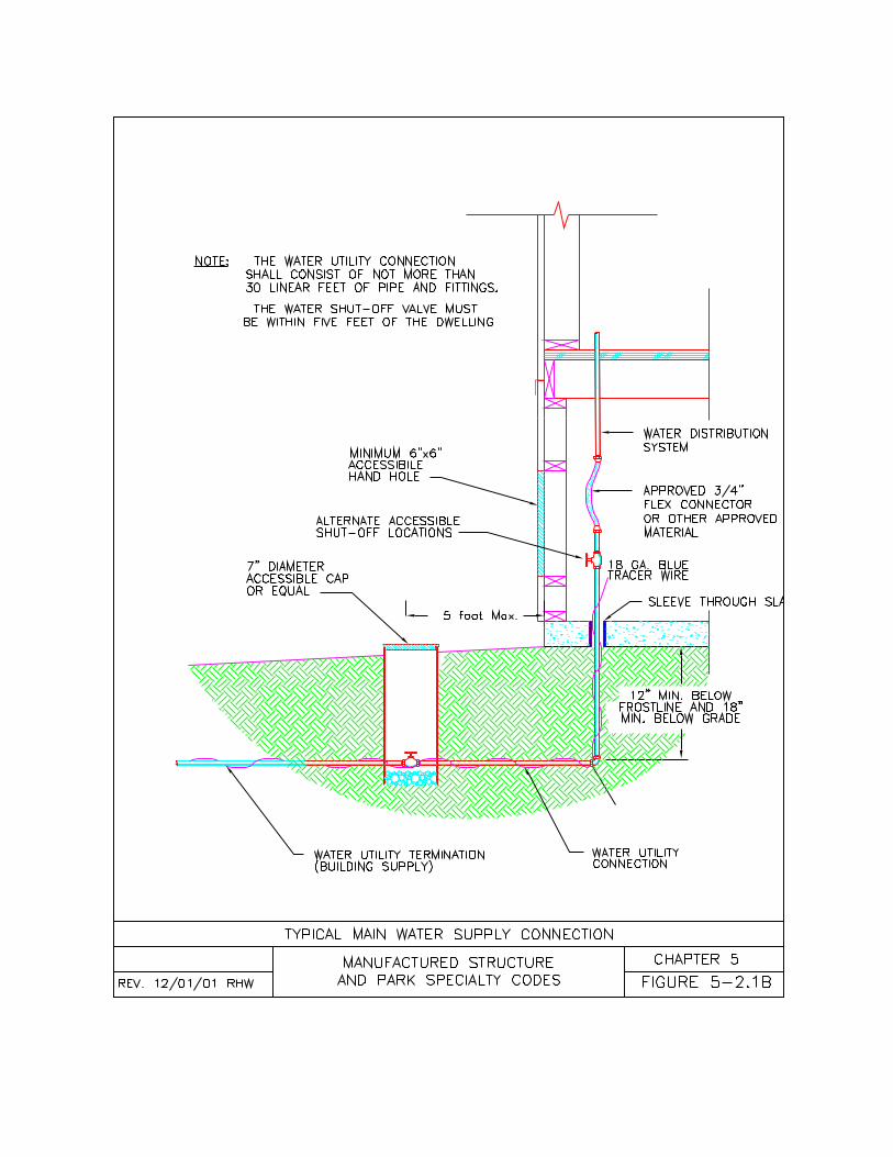
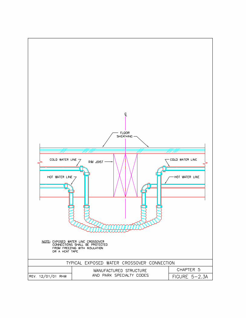
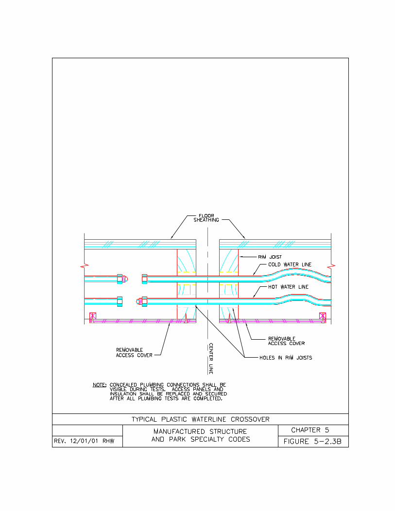
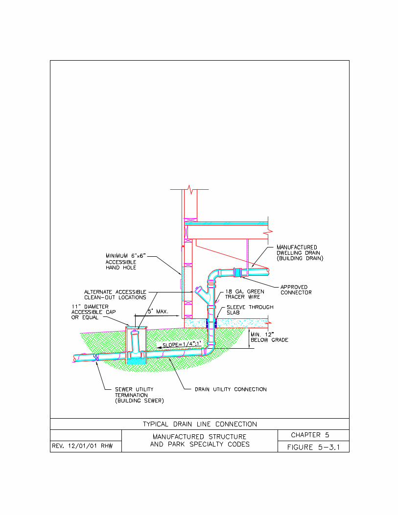
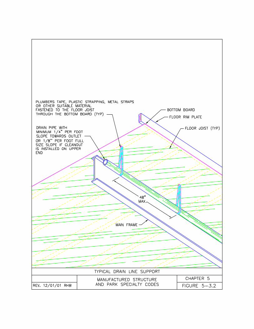
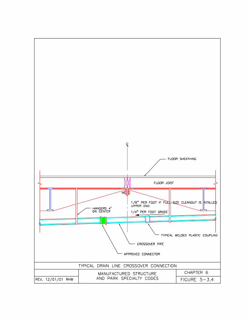
99
CHAPTER 6MECHANICAL INSTALLATIONS
6-1 General6-2 Appliance Installations6-3 Specific Appliances6-4 Fuel Gas Connections6-5 Gas Tests6-6 Oil Fired Appliances
6-1 General6-1.1 Mechanical Installations. Thischapter of the code is intended tosupplement the mechanical requirementsof the federal Manufactured HomeConstruction and Safety Standards 24CFR 3280, the Oregon One and TwoFamily Specialty Code, and the OregonMechanical Specialty Code, but is notintended to take the place of these codesentirely.(a) Where ever the requirements of thiscode differ from the Oregon One andTwo Family Specialty Code, or theOregon Mechanical Specialty Code,this code shall apply;(b) Alternate methods and materialspermitted in the Oregon One and TwoFamily Specialty Code, or the OregonMechanical Specialty Code but notmentioned in this code may be approvedif acceptable to the authority havingjurisdiction;(c) All equipment and material shall bewithout defect. All damaged equipmentand materials shall be discarded andreplaced with approved component parts;(d) All mechanical installation methodsshall be according to the equipmentmanufacturer’s installation instructions,the Manufactured Home Constructionand Safety Standards 24 CFR 3280,this code, and where not specific, to theOregon One and Two Family SpecialtyCode, or the Oregon MechanicalSpecialty code; and(e) All mechanical equipment (i.e.appliances, flues, vents, and ducts) shallbe listed and labeled for the intended use
according to this code or, where notspecific, to the Manufactured HomeConstruction and Safety Standards 24CFR 3280, the Oregon One and TwoFamily Dwelling Specialty Code, or theOregon Mechanical Specialty Code.
6-1.2 Manufactured DwellingEquipment Installations. Installations,alterations, repairs or additions ofmechanical equipment shall comply withthe following:(a) Installations, alterations, repairs oradditions of mechanical equipment priorto or in conjunction with the initial sale ofa manufactured dwelling shall complywith the federal Manufactured HomeConstruction and Safety Standards, 24CFR 3280;(b) Installations, alterations, repairs oradditions of mechanical equipment duringfactory authorized service work on themanufactured dwelling shall comply withthe federal Manufactured HomeConstruction and Safety Standards, 24CFR 3280;(c) Installations, alterations, repairs oradditions of mechanical equipment inconnection with the re-manufacturing orrefurbishing of a manufactured dwellingshall comply with this code and, wherenot specific, with the federalManufactured Home Construction andSafety Standards, 24 CFR 3280;(d) Installations, alterations, repairs oradditions of fuel-burning heat-producingappliances (i.e. fireplaces, fireplacestoves, pellet fired appliances, roomheaters, furnaces, and water heaters)shall comply with this code and, wherenot specific, with the federalManufactured Home Construction andSafety Standards, 24 CFR 3280; and(e) Installations, alterations, repairs oradditions of mechanical equipment afterthe initial sale of a manufactured dwelling,not covered by subsections (a), (b), (c), or(d) of this section, shall comply with thiscode and, where not specific, with theOregon One and Two Family DwellingSpecialty Code.
100
6-2 Appliance Installations.6-2.1 Appliance Installations.Appliances used in conjunction withmanufactured dwellings shall be installedaccording to this Chapter. Applianceswith electrical components are alsorequired to meet the installationrequirements in Chapter 4 of this code.
6-2.2 Listing Requirement. Allappliances and associated equipmentshall be listed for their intended use.Where an appliance listing label ormanufacturer’s installation instructionsstate “Do Not Install or Use InManufactured Homes” or similarlanguage, the appliance shall not beinstalled in a manufactured dwelling.
6-2.3 Installations. All appliances shallbe installed according to their listing, themanufacturer’s Installation instructions,and this code. The manufacturer’sinstallation instructions and operatinginstructions shall be left with theappliance and made available to thehomeowner and the authority havingjurisdiction during inspections.
6-2.4 Access. All appliances andappliance components shall beaccessible for inspection, service, repair,and replacement without removingpermanent construction.
6-2.5 Shipped-Loose Flues and Vents.Appliance chimneys, flues, and vents areoften shipped loose when they exceedthe maximum heights permitted forhighway travel or when they may besubject to damage from road hazards.Shipped loose portions of chimneys,flues, or vents shall be installed accordingto the appliance manufacturer’sinstallation instructions.
6-2.6 Roof Additions and Ramadas.Chimney, flue, or vent sections shall beinstalled through roof additions orramadas according to the appliance’slisting and the manufacturer’s installation
instructions. All required thimbles,flashings, and termination devices shallbe installed through the roof addition orramada according to the appliancemanufacturer’s installation instructions.Chimney, flue, or vent pipe extensionsshall be of the same type, brand, andspecification as the original pipes used inthe manufactured dwelling.
6-2.7 Clearances. Install all appliancesnot less than the minimum clearancesshown in the manufacturer’s installationinstructions.(a) Mechanical installations shall notobstruct the under-floor access to themanufactured dwelling crawl space;(b) Flue gas vents and exhaust ventsshall not terminate less than 3 feet (0.91meters) from any motor driven air intakedischarging into a manufactured dwellingor other habitable areas;(c) Heat pump, air conditioning,evaporative coolers, fans and similarequipment shall not be installed inwindow or door openings which are partof an egress system or in a manner thatwill obstruct sidewalks or egress paths;(d) When a manufactured dwelling islocated in a flood hazard area, allmechanical equipment shall be elevated12 inches (305 mm) above the base floodelevation excepting crossover heat ducts.
6-2.8 Atmospheric Separations. Thereshall be a complete separation of exhaustair, flue gases, combustion air, and drainsfrom the interior of a manufactureddwelling and other enclosed structures.(a) Inlets or outlets of a manufactureddwelling exhaust vent, combustion airvent, return air vent, or any other flue orvent opening shall not be located in anarea where a garage, cabana, basement,or any other confined space is to beattached to a manufactured dwelling;(b) Condensation drains from airconditioning, heat pumps, evaporativecoolers, dehumidifiers, refrigerationequipment or any other appliance orfixture shall not terminate in or under amanufactured dwelling, cabana, garage,
101
basement, or any other confined space;and(c) Flue gas vents or exhaust vents fromany appliance or structure located outsidea manufactured dwelling shall notterminate less than 3 feet (0.91 meters)from a manufactured dwelling window ormotor driven air intake.
6-2.9 Unvented Fuel BurningAppliances. Unvented fuel burning heatproducing appliances are restricted tocooking ranges and clothes dryers only.No other unvented fuel burning heatproducing appliances are permitted to beinstalled in manufactured dwellings.
6-2.10 Additional Equipment. Additionalmechanical equipment added to amanufactured dwelling on site shallcomply with the following:(a) Roof mounted equipment (i.e. airconditioners, evaporative coolers, andsolar panels) add extra weight to the roofof a manufactured dwelling. Unless themanufactured dwelling has beenprepared for these additions by themanufacturer, the roof structure shall bereinforced according to Chapter 7 of thiscode;(b) Wall mounted equipment (i.e. airconditioners, evaporative coolers, andheat pumps) may add substantial loads tothe wall of a manufactured dwelling. If theequipment is more than 100 pounds ( )the exterior wall shall be reinforcedaccording to Chapter 7 unless themanufactured dwelling has beenprepared for these additions by themanufacturer.
6-3 Specific Appliances.6-3.1 Appliance Requirements.Manufactured dwelling appliances shallbe listed according to Table 6-A of thischapter and installed according to thissection. Appliances not specificallymentioned in this section shall be listedfor manufactured home or mobile homeuse and shall be installed according tothe listing and the appliancemanufacturer’s installation instructions.
6-3.2 Air Conditioners and HeatPumps. Air conditioners and heat pumpsused with manufactured dwellings shallbe installed according to this section and,where not specific, to the terms of theirlisting and the appliance manufacturer’sinstallation instructions:(a) Heat pumps or air conditioners addedto a manufactured dwelling during or priorto the initial sale to the first consumershall be listed for manufactured home ormobile home use and shall be specificallylisted for use with the manufactureddwelling’s heating or air handlingequipment;(b) Heat pumps or air conditioners addedto a manufactured dwelling after thecompletion of the initial sales contractshall be listed but do not have to bespecifically listed for use with themanufactured dwelling’s heating or airhandling equipment or listed formanufactured home or mobile home use.This equipment may be used inconjunction with existing manufactureddwelling heating or air handlingequipment if the authority havingjurisdiction determines the equipment iscompatible;(c) Heat pump or air conditioningequipment, installed on the exterior of amanufactured dwelling and not supportedby the manufactured dwelling, shall besupported on a minimum 4 inch (10 cm)thick level concrete slab, a minimum 4inch (10 cm) thick precast concrete slab,a listed mounting base, or according tothe equipment manufacturer’s installationinstructions. The top surface of the slabor base shall be a minimum of 3 inches (8cm) above the finished grade. Theequipment support slab shall be made insuch a manner as to permit the drainageof condensate;(d) When installing an air conditioning coilor box above the furnace, reconnect thefresh air inlet to the furnace as requiredby the appliance manufacturer'sinstallation instructions;(e) External air conditioning or heat pumpducts shall have R-8 insulation and shall
102
be installed and conform to therequirements for heat ducts specified inSection 6-3.5(m) of this chapter.
6-3.3 Clothes Dryers. Clothes dryersshall be installed in manufactureddwellings according to this section and,where not specific, to the terms of theirlisting and the appliance manufacturer’sinstallation instructions:(a) Clothes dryers installed inmanufactured dwelling during or prior tothe initial sale to the first consumer shallbe listed for manufactured home ormobile home use;(b) Clothes dryers installed in amanufactured dwelling after thecompletion of the initial sales contractshall be listed but do not have to be listedfor manufactured home or mobile homeuse; and(c) Except for listed non-venting typeclothes dryers, all clothes dryers shallhave moisture/lint exhaust ducts toremove moisture-laden air from theinterior atmosphere of the manufactureddwelling. Exhaust ducts shall be installedaccording to the following, or where notspecific, to manufacturer’s installationinstructions:1. Exhaust ducts shall be a minimum of 4inches (10 cm) in diameter;2. Exhaust ducts shall be routed throughthe wall, floor, skirting, foundation, orretaining wall to the exterior of themanufactured dwelling or under-floorenclosure;3. Exhaust ducts shall not terminate in orunder a manufactured dwelling, cabana,garage, or any other confined space;4. Exhaust duct material shall be 30gauge rigid sheet metal or flexible metalconforming to UL 181-96;5. Flexible foil, vinyl, or PVC exhaust ductis not permitted to be used with clothesdryers unless specifically permitted by theappliance manufacturer’s installationinstructions;6. Exhaust ducts shall have no dips ortraps in the duct run unless a ¼” (6.35mm) hole is made at the lowest point ofthe exhaust duct;
7. Exhaust ducts shall have no screws,mechanical fasteners, screens or anyother obstructions extending into anyinterior portion of the duct;8. Exhaust ducts shall be maximum of 25feet (7.62 meters), but shall be reduced inlength by 2.5 feet (0.76 meters) for each45 degree bend and 5.0 feet (1.52meters) for each 90 degree bend; and9. The exhaust duct termination shall beequipped with back draft damperproviding full opening by design.
6-3.4 Cooking Ranges and Ovens.Cooking ranges and ovens shall beinstalled in manufactured dwellingsaccording to this section and, where notspecific, to the terms of their listing andthe appliance manufacturer’s installationinstructions:(a) Solid-fuel-burning cooking ranges andovens installed in manufactured dwellingsshall be approved and listed for use inmanufactured homes;(b) Pellet fired cooking ranges and ovensshall be approved and listed for use inmanufactured homes;(c) Antique cooking ranges and ovens arenot permitted in manufactured dwellingsunless specifically listed for manufacturedhome or mobile home use; and(d) Ranges and ovens equipped withintegral down-draft exhaust vents passingthrough the floor or exterior wall of amanufactured dwelling shall be installedaccording to the following:1. Exhaust ducts shall be specificallyinstalled according to the appliancemanufacturer’s installation instructions;2. Exhaust ducts shall be sized accordingto the appliance manufacturer’sinstallation instructions;3. Exhaust ducts shall be routed throughthe wall, floor, skirting, foundation wall, orretaining wall to the exterior according tothe appliance manufacturer’s installationinstructions;4. Exhaust ducts shall have no dips ortraps unless specifically permitted in theappliance manufacturer’s installationinstructions;
103
5. Exhaust ducts shall not terminate in orunder a manufactured dwelling, cabana,garage, or any other confined space;6. Exhaust duct material shall meet theminimum specifications in themanufacturer’s installation instructions;7. Non-metallic or flexible exhaust ductshall not be used for exhaust ductsystems;8. Exhaust ducts shall have no screws,mechanical fasteners, screens or anyother obstructions extending into anyinterior portion of the duct;9. Exhaust ducts shall be limited in lengthaccording to the appliance manufacturer’sinstallation instructions;10. Exhaust ducts shall terminate withproper termination device and a backdraft damper.
6-3.5 Furnaces. Furnaces shall beinstalled in manufactured dwellingsaccording to this section and, where notspecific, to the terms of their listing andthe appliance manufacturer’s installationinstructions:(a) Furnaces installed in a manufactureddwelling during or prior to the initial saleto the first consumer shall be listed formanufactured home or mobile home use;(b) Furnaces installed in a manufactureddwelling after the completion of the initialsales contract shall be listed but do nothave to be listed for manufactured homeor mobile home use;(c) Fuel-burning furnaces shall beinstalled to provide for the completeseparation of the combustion system fromthe interior atmosphere of themanufactured dwelling by:1. The installation of a listed direct vent(sealed combustion system) appliance; or2. The installation of the appliance withinan enclosure accessible only from outsidethe manufactured dwelling so as toseparate the appliance combustion andventing systems from the interioratmosphere of the manufactureddwelling. There shall not be any door,removable access panel, or otheropening into the enclosure from the insideof the manufactured dwelling. Any
openings or penetrations for ducts returnair inlets, piping or wiring shall be sealedwith non-combustible caulking or equal.(d) Fuel-burning furnaces shall beequipped with a direct vent combustionair inlet designed to conduct air directlyinto the fire chamber. Combustion airshall not be taken from within anymanufactured dwelling wall, floor, orceiling cavity or from a garage, cabana,basement, or other confined area.Combustion air may be taken from aventilated crawl space below themanufactured dwelling. Combustion airinlets shall be listed or certified ascomponents of the appliance;(e) Flue gas vents shall be installedaccording to the listing and the appliancemanufacturer’s installation instructions.Flue gas vents shall be listed or certifiedas components of the appliance;(f) Clearances surrounding furnaces shallnot be less than those clearancesspecified in the terms of the listing andthe appliance manufacturer’s installationinstructions;(g) Pellet-fired furnaces shall be installedaccording to section 6-3.9 of this chapter;(h) Solid-fuel-burning furnaces shall beinstalled according to section 6-3.10 ofthis chapter;(i) Kerosene and oil-fired furnaces shallbe listed according to UL 826 andinstalled according to the Standard forthe Installation of Oil-BurningEquipment (NFPA 31) and this section ofthe code; and(j) Under-floor manufactured dwellingheating and air conditioning ducts shallbe installed according to the following:1. Under-floor duct material shall be listedto UL 181-96;2. Under-floor duct material shall have aminimum of R-8 insulation, a vaporretarder rated at 1.0 perm or less, aninner liner of spring steel wire helixbanded within two layers of 57 gaugemylar polyester film or equal, and aninterior diameter not less than thediameter of the plenum collars on themanufactured dwelling;
104
3. Where extensions, splices or sharpturns (when the inside radius is less thanthe inside diameter of the duct) are used,they shall be made with 28 gauge sheetmetal extensions, elbows, tees, wyes, orcollars secured with proper mechanicalfasteners with each seam and jointsealed with foil tape or other approvedduct sealer. The insulation and a vaporrequired above shall be installed on allsheet metal extensions, elbows, tees,wyes, and collars;4. Inner liner shall be secured to theextension, elbow, tee, wye, or collar withproper mechanical fasteners and installedso the insulation and vapor retarderextends up into the floor insulation andbottom board;5. Outer liner, insulation, and vaporretarder shall be secured to theextension, elbow or collar with stainlesssteel worm drive clamps or nylon straps.Stainless steel worm drive clamps, nylonstraps, and all duct vapor retarder jointsshall be sealed with approved foil tape orother approved duct sealer;6. Adequate clearances shall bemaintained under the manufactureddwelling for the under-floor heat and airconditioning ducts. Ducts shall beelevated above the ground, footing, orslab a minimum of 1 inch (25 mm) withmasonry or pressure treated blocks orstraps; and7. Under-floor heat and air conditioningducts shall be installed with a minimum ofbends and excess length so not to restrictairflow. Ducts shall be supported andconnected according to the duct andappliance manufacturer’s instructions,shall have a minimum of bends, shall nothave sharp bends, shall not haveexcessive length, shall not have stress atthe connections, and shall not becrushed, dented, or compressed. Alltears, holes, and penetrations shall besealed with approved foil tape or otherapproved duct sealer.
6-3.6 Gas-Fired Fireplaces. Gas-firedfireplaces, fireplace stoves, and roomheaters shall be installed in manufactured
dwellings according to this section and,where not specific, to the terms of theirlisting and the appliance manufacturer’sinstallation instructions. In addition theyshall meet the following:(a) Be listed and labeled formanufactured home or mobile home use;(b) Have a shut off valves installed on thesupply side of the appliance;(c) Be equipped with a safeguard deviceto automatically shut off the fuel supplywhen the means of ignition of suchburners become inoperable;(d) Have clearances not be less thanthose clearances specified in the terms ofthe listing and the manufacturer’sinstallation instructions;(e) Not be installed in alcoves unlessspecifically allowed in the appliancemanufacturer’s installation instructionsand product listing;(f) Be located in a manufactured dwellingso no doors, drapes or other suchmaterial can be placed or swing closer tothe appliance than the clearancesspecified on the labeled equipment.Sufficient room shall be available toenable the operator to observe theburner, control, and means of ignitionwhile starting the appliance;(g) Have a hearth extension installedwhen required by the appliance listing ormanufacturer’s installation instructions;(h) Have a 1-inch (25.4 mm) air spacebetween the heat shield and any verticalwall surface. Heat shields shall notreduce the clearances of gas-firedfireplaces, fireplace stoves, and roomheaters unless specifically permitted inthe appliance manufacturer’s installationinstructions and product listing.(i) Be secured to the manufactureddwelling floor to avoid displacementduring transportation;(j) Be sealed combustion appliancesequipped with a direct vent combustionair inlet designed to conduct air directlyinto the fire chamber and installed toprovide for the complete separation of thecombustion system from the interioratmosphere of the manufactureddwelling;
105
(k) Not have combustion air taken fromwithin any manufactured dwelling wall,floor, or ceiling cavity or from a garage,cabana, basement, or other confinedarea. Combustion air may be taken froma ventilated crawl space below themanufactured dwelling. Combustion airinlets shall be listed or certified ascomponents of the appliance;(l) Have exhaust vents installed accordingto the terms of their listings and theappliance manufacturer’s installationinstructions;(m) Gas-fired fireplaces, fireplace stoves,and room heaters may be placed within abedroom if they are sealedcombustion/direct vent
6-3.7 Gas-Fired Log Lighters. Gas-firedlog lighters shall be installed in solid-fuel-burning or gas fired fireplaces accordingto this section and, where not specific, tothe terms of their listing and the appliancemanufacturer’s installation instructions:(a) Gas-fired log lighters shall be listedcomponents of the manufactured homelisted and approved fireplace;(b) Gas-fired log lighters shall be listed,labeled, and installed according to themanufacturer’s installation instructions;(c) Gas-fired log lighters shall have a shutoff valve installed on the supply side ofthe appliance;(d) Gas-fired log lighters shall beequipped with a safeguard device toautomatically shut off the fuel supplywhen the means of ignition of suchburners become inoperable;(e) Clearances surrounding gas-fired loglighters shall not be less than thoseclearances specified in the terms of thelisting; and(f) Gas-fired log lighters shall be locatedin a manufactured dwelling so no doors,drapes or other such material can beplaced or swing closer to the appliancethan the clearances specified on thelabeled equipment.
6-3.8 Pellet-Fired Appliances. Pellet-fired appliances shall be installed inmanufactured dwellings according to this
section and, where not specific, to theterms of their listing and the appliancemanufacturer’s installation instructions:(a) Pellet-fired appliances used inmanufactured dwellings shall be listed foruse manufactured homes and shall meetthe requirements of OregonAdministrative Rule (OAR) 918-520 andthis chapter.(b) The following statement, “This pellet-fired appliance has been constructed,tested and listed for use inmanufactured homes according to theState of Oregon Building Code”;(c) Pellet-fired appliances shall not beinstalled in a manufactured dwellingsleeping room.
6-3.9 Solid-Fuel-Burning Fireplacesand Fireplace Inserts. Solid fuel burningfactory-built fireplaces, fireplace stoves,and room heaters shall be installed inmanufactured dwellings according to thissection and the Manufactured HomeConstruction and Safety Standards 24CFR 3280.709, and where not specific, tothe terms of their listing and the appliancemanufacturer’s installation instructions:(a) Solid-fuel-burning fireplaces, fireplacestoves, and room heaters used inmanufactured dwellings shall be listed foruse manufactured homes or mobilehomes;(b) Solid-fuel-burning fireplaces, fireplacestoves, and room heaters used inmanufactured dwellings shall have apermanently attached label containing thefollowing statements, “For use withsolid fuel only” and “Approved orListed for manufactured home use”.(c) Solid fuel burning fireplaces, fireplacestoves, and room heaters shall not beinstalled in a manufactured dwellingsleeping room unless approved by HUDthrough the alternate constructionprocess prior to production;(d) Solid-fuel-burning fireplaces, fireplacestoves, and room heaters shall not beinstalled in alcoves unless specificallyallowed in the appliance manufacturer’sinstallation instructions and productlisting;
106
(e) Solid-fuel-burning fireplaces, fireplacestoves, and room heaters shall besecured to the manufactured dwellingfloor to avoid displacement duringtransportation;(f) Combustion air shall not be taken fromwithin any manufactured dwelling wall,floor, or ceiling cavity or from a garage,cabana, basement, or other confinedarea. Combustion air may be taken fromthe ventilated crawl space below themanufactured dwelling. Combustion airinlets shall be listed or certified ascomponents of the appliance;(g) Antique solid-fuel-burning fireplacestoves, room heaters, or cooking stovesare not permitted in manufactureddwellings unless specifically listed formanufactured home of mobile home use;and(h) Masonry fireplaces are not permittedin manufactured dwellings. A listedmanufactured home or mobile homefireplace may be installed within amasonry enclosure according to terms ofits listing and the manufacturer’sinstallation instructions if themanufactured dwelling is placed on afoundation or basement according toChapter 3 of this code.
6-3.10 Water Heaters. Water heatersshall be installed in manufactureddwellings according to this section and,where not specific, to the terms of theirlisting and the appliance manufacturer’sinstallation instructions:(a) Water heaters installed in amanufactured dwelling during or prior tothe initial sale to the first consumer shallbe listed for manufactured home ormobile home use;(b) Water heaters installed in amanufactured dwelling after thecompletion of the initial sales contractshall be listed but do not have to be listedfor manufactured home or mobile homeuse;(c) Fuel-burning water heaters shall beinstalled to provide for the completeseparation of the combustion system from
the interior atmosphere of themanufactured dwelling by:1. The installation of a listed direct vent(sealed combustion system) appliance; or2. The installation of the appliance withinan enclosure accessible only from outsidethe manufactured dwelling so as toseparate the appliance combustion andventing systems from the interioratmosphere of the manufactureddwelling. There shall not be any door,removable access panel, or otheropening into the enclosure from the insideof the manufactured dwelling. Anyopenings or penetrations for ducts returnair inlets, piping, or wiring shall be sealedwith non-combustible caulking or equal.(d) Fuel-burning water heaters shall beequipped with a direct vent combustionair inlet designed to conduct air directlyinto the fire chamber. Combustion airshall not be taken from within anymanufactured dwelling wall, floor, orceiling cavity or from a garage, cabana,basement, or other confined area.Combustion air may be taken from aventilated crawl space below themanufactured dwelling;(e) Flue gas vents shall be installedaccording to the listing and the appliancemanufacturer’s installation instructions.Flue gas vents shall be listed or certifiedas components of the appliance;(f) Clearances surrounding water heatersshall not be less than those clearancesspecified in the terms of the listing andthe appliance manufacturer’s installationinstructions;(g) All water heater appliances shall besecured in place to prevent movementduring transportation;(h) Tankless water heaters shall beinstalled according to the product listingand the manufacturer’s installationinstructions.
6-4 Fuel Gas Connections.6-4.1 General. All fuel gas pipingconnections to a manufactured dwellingshall be made according to the minimumrequirements of this code and, where notspecific, to the federal Manufactured
107
Home Construction and SafetyStandards 24 CFR 3280.
6-4.2 Fuel Gas Pipe Assembly. Fuel gaspiping between the manufactureddwelling gas supply inlet and the gassupply outlet shall comply with theOregon One and Two Family DwellingSpecialty Code:
6-4.3 Crossover Connections. Fuel gaspipe running from one section of amanufactured dwelling to another sectionof the same manufactured dwelling shallbe connected at the marriage line(s)according to the following:(a) Crossover piping shall be accessible;(b) Crossover piping shall have an insidediameter equivalent to the piping beingconnected;(c) Crossover piping shall be made ofconnectors supplied by the manufacturer,with flexible connectors listed for exterioruse and a listed quick disconnect device,or with other materials listed in Table 6-B(see Figure 6-5.6);(d) If a quick disconnect device is notused, an approved shutoff valve isrequired at each crossover pointupstream of the connection; and(e) Crossover piping shall be supportedaccording to Table 6-D of this code.
6-4.4 Gas Pipe Extensions. Where it isnecessary to extend the manufactureddwelling gas supply inlet under themanufactured dwelling to reach the pointof connection to the gas supply outlet, theextension shall be installed according tothe following:(a) All pipe extensions shall be sizedaccording to Table 6-C of this chapterbased on the length of the piping and thetotal demand of all appliances. Where thedemand of an appliance is not known useTable 6-E of this chapter; and(b) All pipe extensions shall be closelyrouted against the manufactured dwellingmain frame, secured, protected fromphysical damage, and supportedaccording to Table 6-D of this code.
6-4.5 Gas Shutoff Valve. Where fuel gasis provided, each manufactured dwellingsite shall have a listed gas shutoff valveinstalled upstream from the manufactureddwelling site gas outlet riser at a height ofnot less than 6 inches (152 mm) abovegrade. Such valve shall not be locatedunder any manufactured dwelling oraccessory building. The required shutoffvalve shall be within 5 feet (157 cm) ofthe manufactured dwelling exterior wall.Gas valves shall conform to ANSI Z21.15or ASME B16.33. This gas valve may beeliminated when there is a shutoff valveor cock provided with the gas meterserving the same manufactured dwellingon the same lot. Unused gas supplyoutlets shall be equipped with a cap orplug to prevent discharge of gaswhenever the outlet is not connected to amanufactured dwelling or cabana (seeFigures 6-4.5 and 6-4.5A).
6-4.6 Gas Supply Connections. Eachgas supply shall be connected to themanufactured dwelling according to thefollowing:(a) Manufactured dwellings supported byand secured to foundation walls orbasement walls shall be connected to thegas supply with a 2 foot (61 cm) flexiblegas connector or with steel ferrous pipeand fittings;(b) Manufactured dwellings supported onpiers and having perimeter skirting shallbe connected to the gas supply accordingto the following:1. In seismic zone 2b, the gas supplyconnector shall be an approved 2 foot (61cm) flexible gas connector (See Map 3-C);2. In seismic zones 3 and 4, the gassupply connector shall be an approved 6foot (183 cm) flexible gas connector (SeeMap 3-C;4. In the Standard Wind Area, the gassupply connector shall be an approved 2foot (61 cm) flexible gas connector (SeeMap 3-A);5. In the High Wind Area, the gas supplyconnector shall be an approved 6 foot
108
(183 cm) flexible gas connector (See Map3-A); and6. Where the connector size is differentbetween the applicable wind zone andseismic zone, use the longer of the twoflexible gas connectors.(c) 6 foot (183 cm) flexible gasconnectors shall be installed between thegas supply connector and themanufactured dwelling gas supply inlet ina “U” shape to allow for movement of thehome during high winds or a seismicevent;(d) Required flexible gas connectors shallbe listed in Table 6-B of this chapter;(e) Flexible gas connectors shall be sizedand have a capacity rating adequate tosupply the connected load according toTable 6-F of this code;(f) Required flexible gas connectors maybe replaced with swing joint connectionsif provided with listed automaticearthquake shutoff devices;(g) Connectors shall be sized equivalentto the inside diameter of themanufactured dwelling’s gas supply inletpipe. Where the manufactured dwelling isbeing converted to gas or where gasappliances are being added, the supplypiping shall be sized according to Table6-C of this chapter based on the length ofthe piping and the total demand of allappliances. Where the demand of anappliance is not known use Table 6-E ofthis code; and(h) Where cathodic protection is providedon the gas supply system, a dielectricfitting shall be used in the manufactureddwelling gas connection to insulate themanufactured dwelling.
6-5 Gas Tests6-5.1 Gas Tests. Gas tests are requiredby the person making the gasconnections to the manufactured dwellingwhether the homeowner, installer, or gasutility company. The gas system in amanufactured dwelling has beendesigned to operate within ½ PSI to ¼PSI. A tag may have been attached to thegas inlet indicating the size and BTU of
the listed gas supply connector to beused.
6-5.2 Test Preparation. Prior tobeginning the gas test, make thefollowing preparations:(a) Verify the orifices of all fuel burningappliances are correct for the type of fuelused;(b) If the manufactured dwelling is locatedat or above 3,000 feet above sea level,special orifices and regulators may berequired, see appliance manufacturer’sinstallation instructions;(c) Verify the temperature of the ambientair and the piping are approximately thesame and conduct the test at such a timeduring the day when the air temperatureswill remain constant;(d) If the gas supply from any sourceexceeds ½ PSI or 8 ounces install apressure reducing valve; and(e) Verify each gas appliance flue pipe,vent, roof jack has been properly installedand secured to the appliance..6-5.3 Gas Line Test. After installation ofthe manufactured dwelling, the fuel gaspiping system shall be subjected topressure testing according to both of thetwo following methods:(a) The gas lines and connections shallbe subjected to a test with the systempressurized with air according to thefollowing steps:1. With all appliance shut off valvesclosed, subject the piping system to three(3) PSI for a period of not less than tenminutes without showing any drop inpressure.2. If there is a drop in pressure, locatedthe source of the leak and correct asnecessary.3. If a leak has been repaired, then retestthe system again with the appliance shutoff valves closed and subjecting thepiping system to three (3) PSI for a periodof not less than ten minutes withoutshowing any drop in pressure.(b) After completing a successful pipingtest, release the air pressure, open all theappliance shut off valves and pressurize
109
the system with a continual pressurebetween 6 to 8 ounces.1. Test each connection from the shut offvalve to the appliance with a suitablesoapy water or bubble solution.2. Make appropriate corrections if there isany evidence of leakage at thoseconnections.3. Repeat testing until all leaks have beeneliminated.4. When the testing is completed, thesoap or bubble solution must be washedfrom the connection with water to preventcorrosion of the fitting.
6-6 Oil Fired Appliances6.6.1 General. Fuel oil appliances inmanufactured dwellings shall have thefuel oil supply line connected to theappliance on site. All fuel oil pipingsystems serving a manufactured dwellingshall be installed according to theminimum requirements of Chapter 14 theOregon Mechanical Specialty Code,and, where not specific, to the OregonOne and Two Family Specialty Code.
6-6.2 Appliances Kerosene and oil-firedroom heaters and water heaters shall belisted according to UL 826 and installedaccording to the Standard for theInstallation of Oil-Burning Equipment(NFPA 31-97) and this section of thecode.
6-6.3 Storage Systems. Fuel oil storagesystems shall comply with the following:(a) Fuel oil storage tanks and supplypiping systems shall be installedaccording to the requirements of thecurrent Oregon Uniform Fire Code andthe Oregon Department ofEnvironmental Quality.
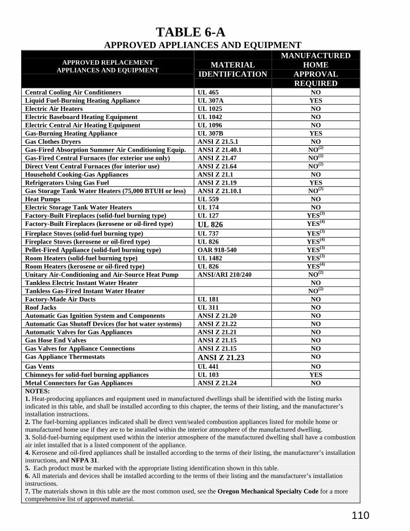
110
TABLE 6-AAPPROVED APPLIANCES AND EQUIPMENT
APPROVED REPLACEMENTAPPLIANCES AND EQUIPMENT
MATERIALIDENTIFICATION
MANUFACTUREDHOME
APPROVALREQUIRED
Central Cooling Air Conditioners UL 465 NOLiquid Fuel-Burning Heating Appliance UL 307A YESElectric Air Heaters UL 1025 NOElectric Baseboard Heating Equipment UL 1042 NOElectric Central Air Heating Equipment UL 1096 NOGas-Burning Heating Appliance UL 307B YESGas Clothes Dryers ANSI Z 21.5.1 NOGas-Fired Absorption Summer Air Conditioning Equip. ANSI Z 21.40.1 NO(2)
Gas-Fired Central Furnaces (for exterior use only) ANSI Z 21.47 NO(2)
Direct Vent Central Furnaces (for interior use) ANSI Z 21.64 NO(2)
Household Cooking-Gas Appliances ANSI Z 21.1 NORefrigerators Using Gas Fuel ANSI Z 21.19 YESGas Storage Tank Water Heaters (75,000 BTUH or less) ANSI Z 21.10.1 NO(2)
Heat Pumps UL 559 NOElectric Storage Tank Water Heaters UL 174 NOFactory-Built Fireplaces (solid-fuel burning type) UL 127 YES(3)
Factory-Built Fireplaces (kerosene or oil-fired type) UL 826 YES(4)
Fireplace Stoves (solid-fuel burning type) UL 737 YES(3)
Fireplace Stoves (kerosene or oil-fired type) UL 826 YES(4)
Pellet-Fired Appliance (solid-fuel burning type) OAR 918-540 YES(3)
Room Heaters (solid-fuel burning type) UL 1482 YES(3)
Room Heaters (kerosene or oil-fired type) UL 826 YES(4)
Unitary Air-Conditioning and Air-Source Heat Pump ANSI/ARI 210/240 NO(2)
Tankless Electric Instant Water Heater NOTankless Gas-Fired Instant Water Heater NO(2)
Factory-Made Air Ducts UL 181 NORoof Jacks UL 311 NOAutomatic Gas Ignition System and Components ANSI Z 21.20 NOAutomatic Gas Shutoff Devices (for hot water systems) ANSI Z 21.22 NOAutomatic Valves for Gas Appliances ANSI Z 21.21 NOGas Hose End Valves ANSI Z 21.15 NOGas Valves for Appliance Connections ANSI Z 21.15 NOGas Appliance Thermostats ANSI Z 21.23 NO
Gas Vents UL 441 NOChimneys for solid-fuel burning appliances UL 103 YESMetal Connectors for Gas Appliances ANSI Z 21.24 NONOTES:1. Heat-producing appliances and equipment used in manufactured dwellings shall be identified with the listing marksindicated in this table, and shall be installed according to this chapter, the terms of their listing, and the manufacturer’sinstallation instructions.2. The fuel-burning appliances indicated shall be direct vent/sealed combustion appliances listed for mobile home ormanufactured home use if they are to be installed within the interior atmosphere of the manufactured dwelling.3. Solid-fuel-burning equipment used within the interior atmosphere of the manufactured dwelling shall have a combustionair inlet installed that is a listed component of the appliance.4. Kerosene and oil-fired appliances shall be installed according to the terms of their listing, the manufacturer’s installationinstructions, and NFPA 31.5. Each product must be marked with the appropriate listing identification shown in this table.6. All materials and devices shall be installed according to the terms of their listing and the manufacturer’s installationinstructions.7. The materials shown in this table are the most common used, see the Oregon Mechanical Specialty Code for a morecomprehensive list of approved material.
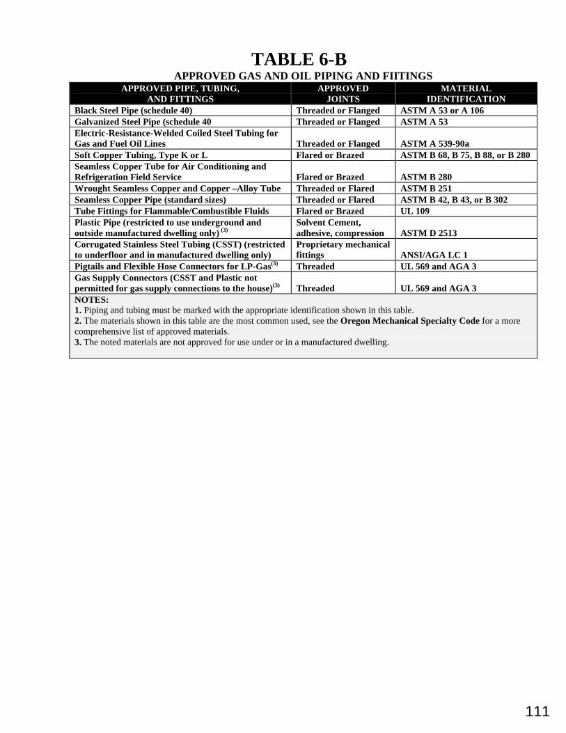
111
TABLE 6-BAPPROVED GAS AND OIL PIPING AND FIITINGS
APPROVED PIPE, TUBING,AND FITTINGS
APPROVEDJOINTS
MATERIALIDENTIFICATION
Black Steel Pipe (schedule 40) Threaded or Flanged ASTM A 53 or A 106Galvanized Steel Pipe (schedule 40 Threaded or Flanged ASTM A 53Electric-Resistance-Welded Coiled Steel Tubing forGas and Fuel Oil Lines Threaded or Flanged ASTM A 539-90aSoft Copper Tubing, Type K or L Flared or Brazed ASTM B 68, B 75, B 88, or B 280Seamless Copper Tube for Air Conditioning andRefrigeration Field Service Flared or Brazed ASTM B 280Wrought Seamless Copper and Copper –Alloy Tube Threaded or Flared ASTM B 251Seamless Copper Pipe (standard sizes) Threaded or Flared ASTM B 42, B 43, or B 302Tube Fittings for Flammable/Combustible Fluids Flared or Brazed UL 109Plastic Pipe (restricted to use underground andoutside manufactured dwelling only) (3)
Solvent Cement,adhesive, compression ASTM D 2513
Corrugated Stainless Steel Tubing (CSST) (restrictedto underfloor and in manufactured dwelling only)
Proprietary mechanicalfittings ANSI/AGA LC 1
Pigtails and Flexible Hose Connectors for LP-Gas(3) Threaded UL 569 and AGA 3Gas Supply Connectors (CSST and Plastic notpermitted for gas supply connections to the house)(3) Threaded UL 569 and AGA 3NOTES:1. Piping and tubing must be marked with the appropriate identification shown in this table.2. The materials shown in this table are the most common used, see the Oregon Mechanical Specialty Code for a morecomprehensive list of approved materials.3. The noted materials are not approved for use under or in a manufactured dwelling.
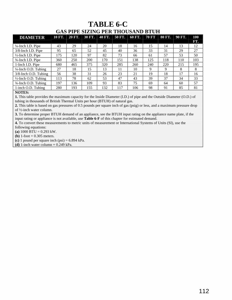
112
TABLE 6-CGAS PIPE SIZING PER THOUSAND BTUH
DIAMETER 10 FT. 20 FT. 30 FT. 40 FT. 50 FT. 60 FT. 70 FT 80 FT. 90 FT. 100FT.
¼-Inch I.D. Pipe 43 29 24 20 18 16 15 14 13 123/8-Inch I.D. Pipe 95 65 52 45 40 36 33 31 29 27½-Inch I.D. Pipe 175 120 97 82 73 66 61 57 53 50¾-Inch I.D. Pipe 360 250 200 170 151 138 125 118 110 1031-Inch I.D. Pipe 680 465 375 320 285 260 240 220 215 195¼-Inch O.D. Tubing 27 18 15 13 11 10 9 9 8 83/8-Inch O.D. Tubing 56 38 31 26 23 21 19 18 17 16½-Inch O.D. Tubing 113 78 62 53 47 43 39 37 34 33¾-Inch O.D. Tubing 197 136 109 93 83 75 69 64 60 571-inch O.D. Tubing 280 193 155 132 117 106 98 91 85 81NOTES:1. This table provides the maximum capacity for the Inside Diameter (I.D.) of pipe and the Outside Diameter (O.D.) oftubing in thousands of British Thermal Units per hour (BTUH) of natural gas.2. This table is based on gas pressures of 0.5 pounds per square inch of gas (psig) or less, and a maximum pressure dropof ½-inch water column.3. To determine proper BTUH demand of an appliance, see the BTUH input rating on the appliance name plate, if theinput rating or appliance is not available, use Table 6-F of this chapter for estimated demand.4. To convert these measurements to metric units of measurement or International Systems of Units (SI), use thefollowing equations:(a) 1000 BTU = 0.293 kW.(b) 1-foot = 0.305 meters.(c) 1 pound per square inch (psi) = 6.894 kPa.(d) 1-inch water column = 0.249 kPa.
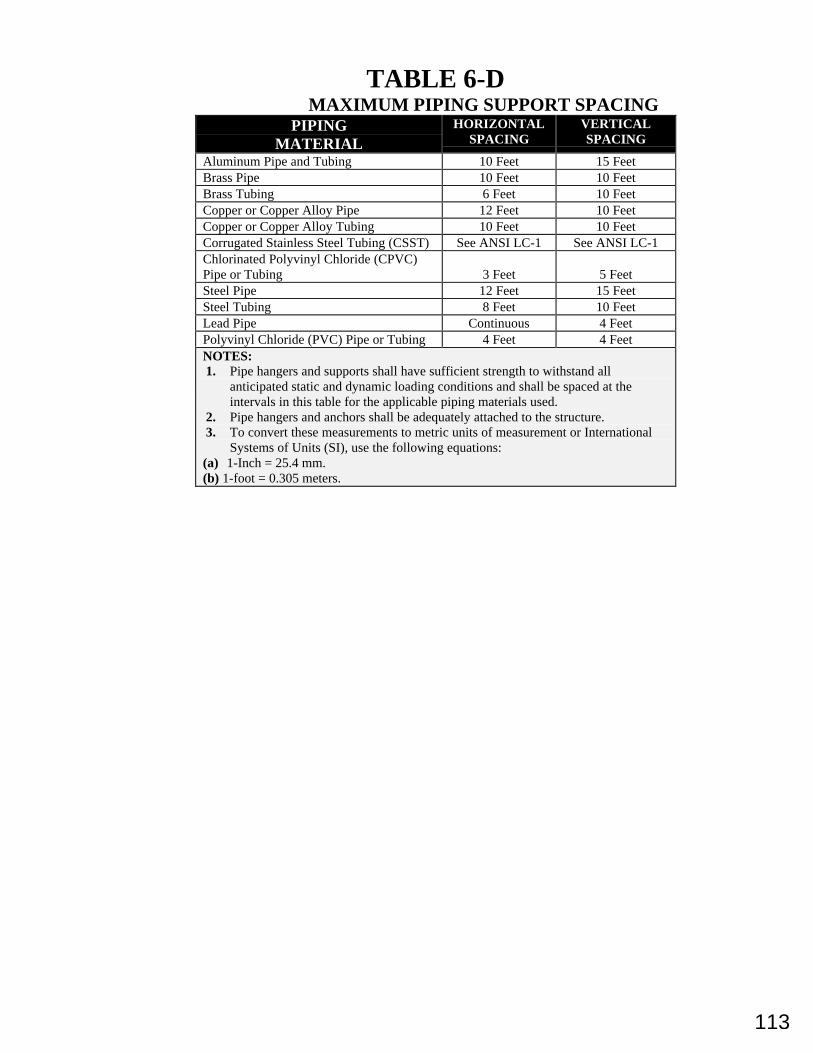
113
TABLE 6-DMAXIMUM PIPING SUPPORT SPACING
PIPINGMATERIAL
HORIZONTALSPACING
VERTICALSPACING
Aluminum Pipe and Tubing 10 Feet 15 FeetBrass Pipe 10 Feet 10 FeetBrass Tubing 6 Feet 10 FeetCopper or Copper Alloy Pipe 12 Feet 10 FeetCopper or Copper Alloy Tubing 10 Feet 10 FeetCorrugated Stainless Steel Tubing (CSST) See ANSI LC-1 See ANSI LC-1Chlorinated Polyvinyl Chloride (CPVC)Pipe or Tubing 3 Feet 5 FeetSteel Pipe 12 Feet 15 FeetSteel Tubing 8 Feet 10 FeetLead Pipe Continuous 4 FeetPolyvinyl Chloride (PVC) Pipe or Tubing 4 Feet 4 FeetNOTES:1. Pipe hangers and supports shall have sufficient strength to withstand all
anticipated static and dynamic loading conditions and shall be spaced at theintervals in this table for the applicable piping materials used.
2. Pipe hangers and anchors shall be adequately attached to the structure.3. To convert these measurements to metric units of measurement or International
Systems of Units (SI), use the following equations:(a) 1-Inch = 25.4 mm.(b) 1-foot = 0.305 meters.
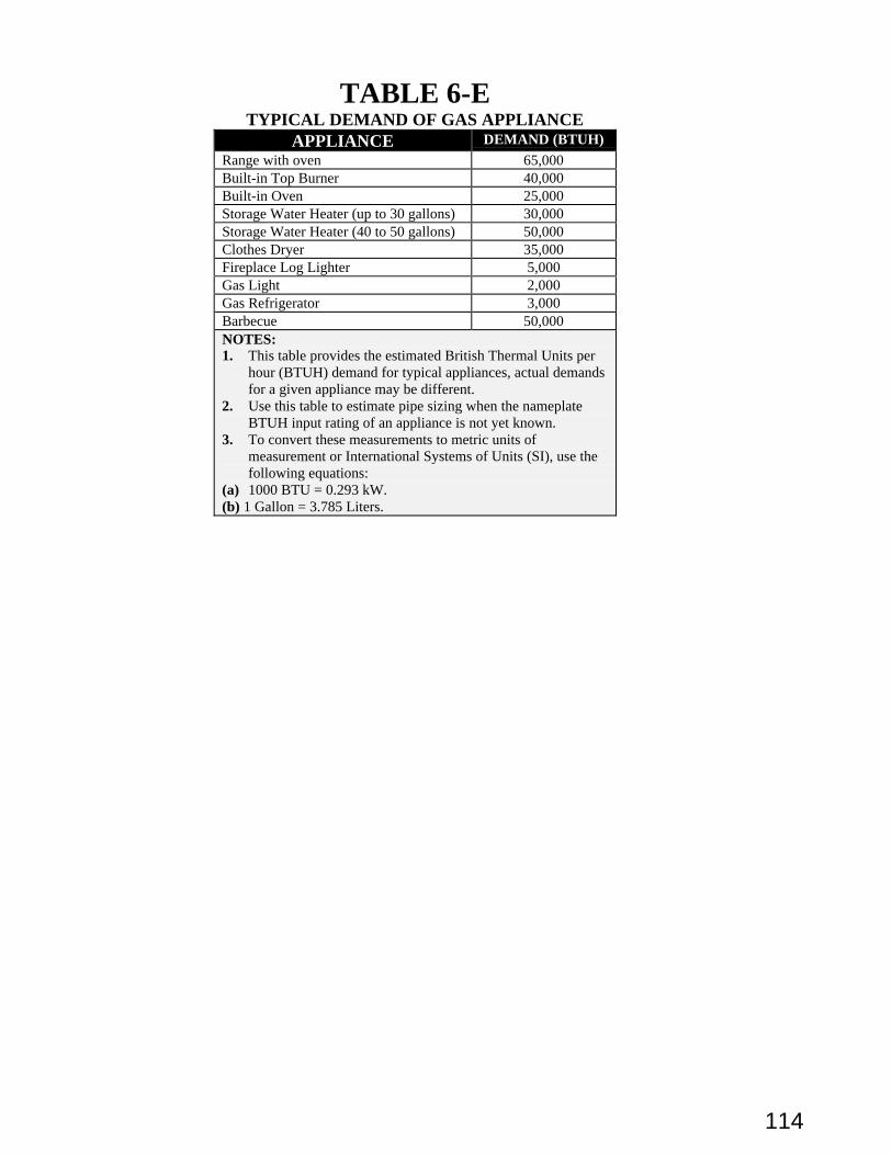
114
TABLE 6-ETYPICAL DEMAND OF GAS APPLIANCE
APPLIANCE DEMAND (BTUH)
Range with oven 65,000Built-in Top Burner 40,000Built-in Oven 25,000Storage Water Heater (up to 30 gallons) 30,000Storage Water Heater (40 to 50 gallons) 50,000Clothes Dryer 35,000Fireplace Log Lighter 5,000Gas Light 2,000Gas Refrigerator 3,000Barbecue 50,000NOTES:1. This table provides the estimated British Thermal Units per
hour (BTUH) demand for typical appliances, actual demandsfor a given appliance may be different.
2. Use this table to estimate pipe sizing when the nameplateBTUH input rating of an appliance is not yet known.
3. To convert these measurements to metric units ofmeasurement or International Systems of Units (SI), use thefollowing equations:
(a) 1000 BTU = 0.293 kW.(b) 1 Gallon = 3.785 Liters.
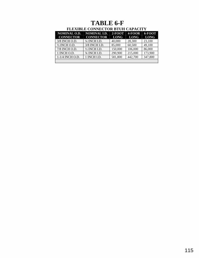
115
TABLE 6-FFLEXIBLE CONNECTOR BTUH CAPACITY
NOMINAL O.D.CONNECTOR
NOMINAL I.D.CONNECTOR
2-FOOTLONG
4-FOORLONG
6-FOOTLONG
3/8 INCH O.D. ¼ INCH I.D. 40,000 28,300 23,100½ INCH O.D. 3/8 INCH I.D. 85,000 60,500 49,1007/8 INCH O.D. ½ INCH I.D. 150,000 106,000 86,0001 INCH O.D. ¾ INCH I.D. 290,900 215,000 173,9001-1/4 INCH O.D. 1 INCH I.D. 581,800 442,700 347,800
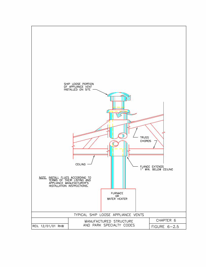
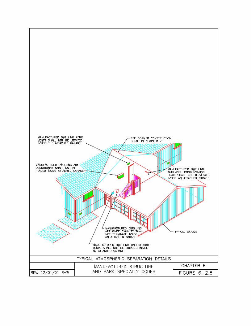
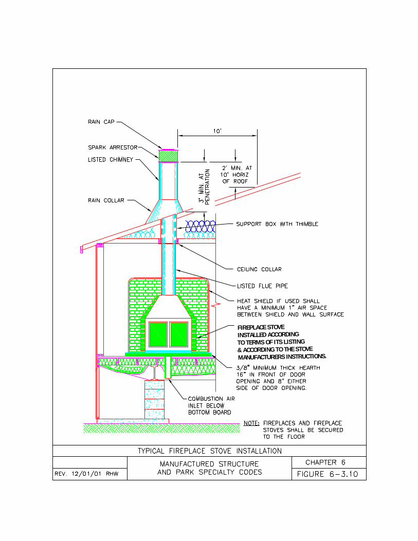
FIREPLACE STOVE INSTALLED ACCORDINGTO TERMS OF ITS LISTING& ACCORDING TO THE STOVEMANUFACTURERS INSTRUCTIONS.
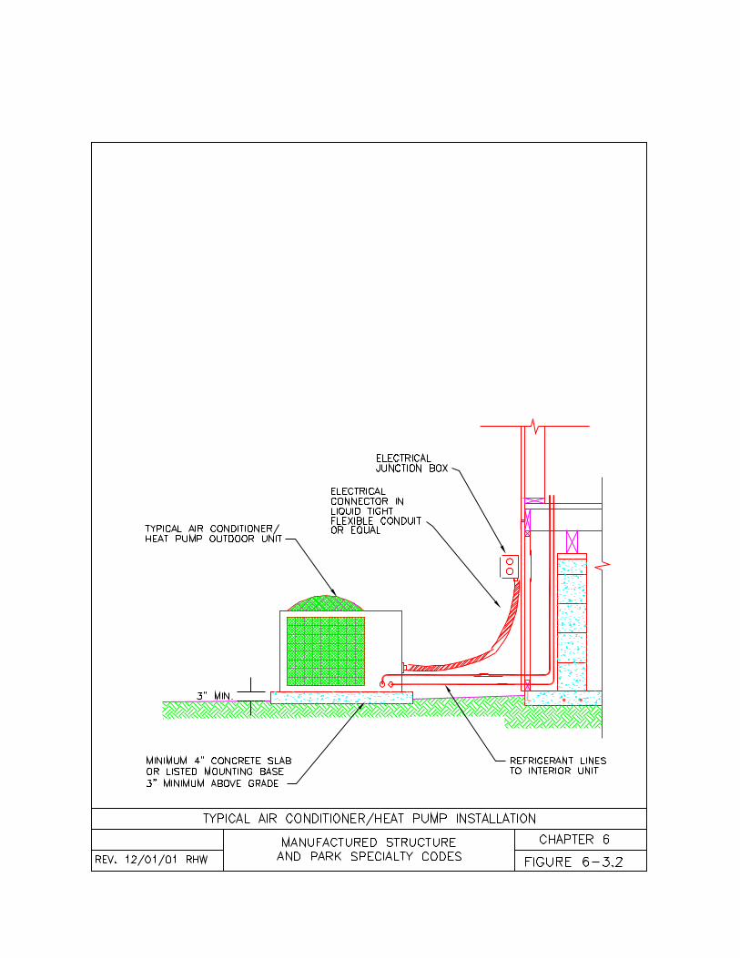
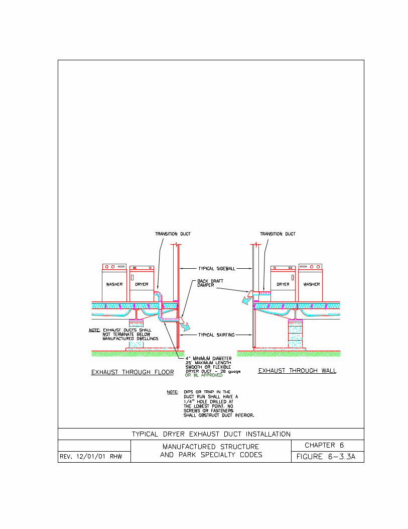
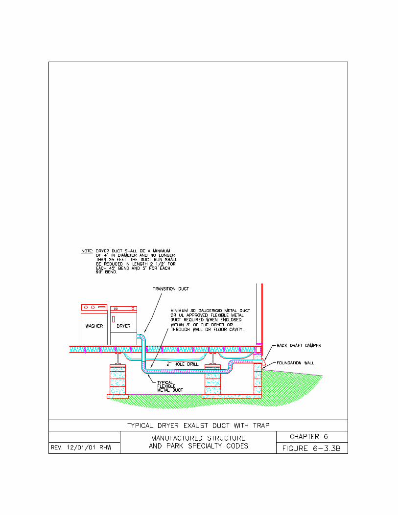
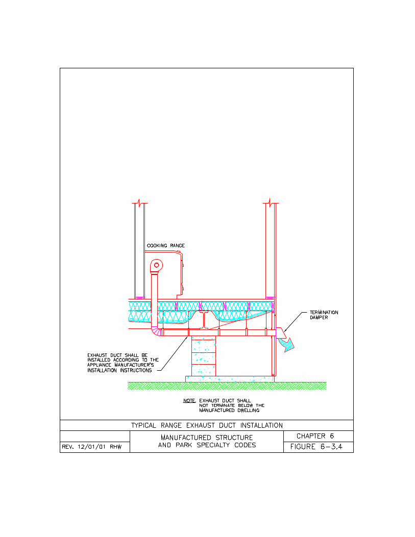
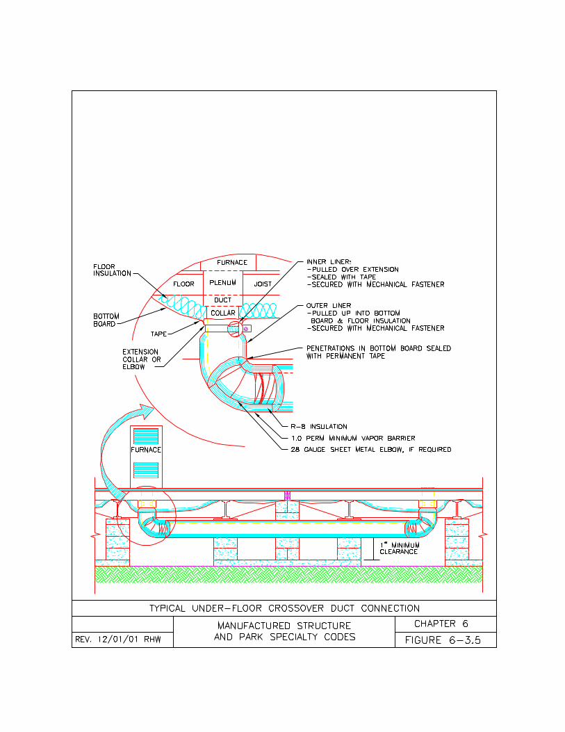
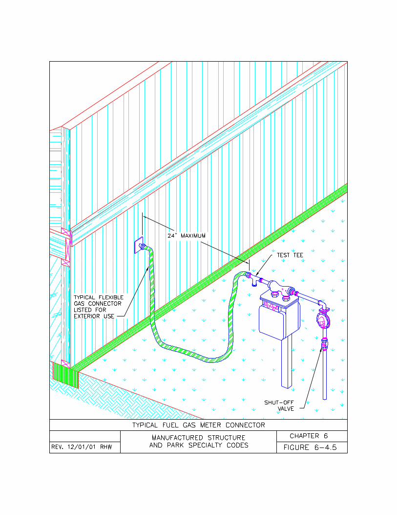
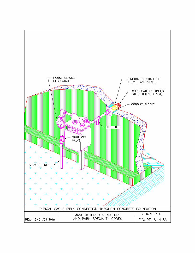
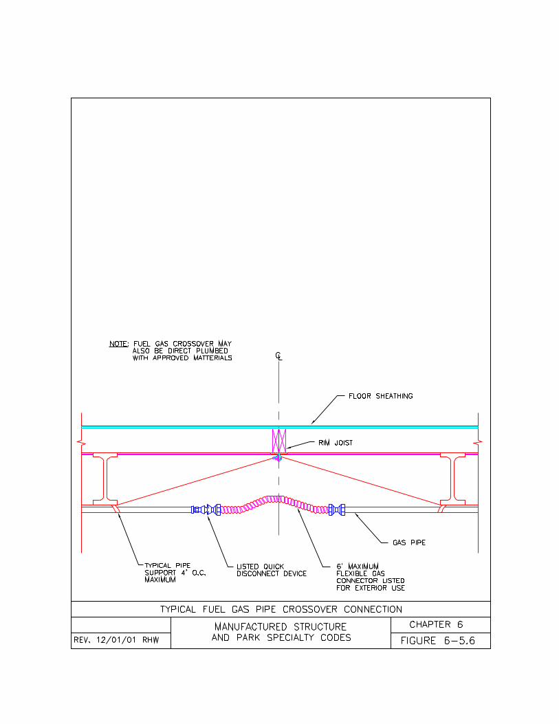
117
CHAPTER SEVENALTERATIONS AND REPAIRS
7-1 General7-2 Alterations7-3 Repairs and Maintenance7-4 Conversion7-5 Re-Roofing7-6 Roof Additions7-7 Dormers and Gables7-8 Re-Furbishing7-9 Substantial Equivalence to HUD7-10 Re-Manufacturing
7-1General.7-1.1 Permits Permits may be requiredfor some work or some portions of thework outlined in this chapter. Refer to thespecific sections of this code, ChapterOne, and the authority having jurisdictionfor more information.7-1.2 Alterations. The term “alterations”,as used in this section of this code only,is meant to include any change, addition,alteration, repair, conversion,replacement, modification, refurbishing,re-manufacturing, or removal of any partof the manufactured dwelling ormanufactured dwelling equipment. Allother sections of the code address only aspecific type of alteration (i.e. repair orconversion). This chapter of the code isintended to supplement the structuralrequirements of the federalManufactured Home Construction andSafety Standards 24 CFR 3280, and theOregon One and Two Family DwellingSpecialty Code, but is not intended totake the place of these codes.(a) Where ever the requirements of thiscode differ from the Oregon One andTwo Family Dwelling Specialty Code,this code shall apply;(b) Alternate methods permitted in theOregon One and Two Family DwellingSpecialty Code, but not mentioned inthis code may be permitted if acceptableto the authority having jurisdiction;(c) All materials used in the alteration of amanufactured dwelling shall be without
defect. All damaged materials shall bediscarded and replaced;(d) All lumber used in the alteration of amanufactured dwelling shall be kiln driedor shall have a moisture content of 19percent or less;(e) Alterations shall not be made to amanufactured dwelling that wouldeliminate required windows, doors, orventilation;(f) Changes in use of a manufactureddwelling shall comply with Chapter 2 ofthis code;(g) All electrical alterations shall complywith Chapter 4 of this code;(h) All plumbing alterations shall complywith Chapter 5 of this code;(i) All mechanical alterations shall complywith Chapter 6 of this code; and(j) Fixtures and appliances shall not bealtered or converted except wherespecifically permitted by the fixture orappliance listing and Chapters 4 and 6 ofthis code.
7-1.3 Alternate Methods. Where it isimpractical for the manufactured dwellingto conform to the strict letter of the code,the inspector may accept methods ormaterials that are substantially equivalentto the code. Engineering may be requiredto substantiate equivalency if structuralcomponents of the manufactured dwellinghave been altered or replaced.
7-1.4 Exempt Alterations. The followingalterations are exempt from permits butare not exempt from the requirements ofthis code:(a) Minor repairs with approvedcomponent parts;(b) Conversion of listed fuel burningappliances in accordance with the termsof their listing;(c) Adjustment and maintenance ofequipment; and(d) Replacement of equipment oraccessories in kind.
NOTE: For a more complete descriptionof what is included in exempt alterations,
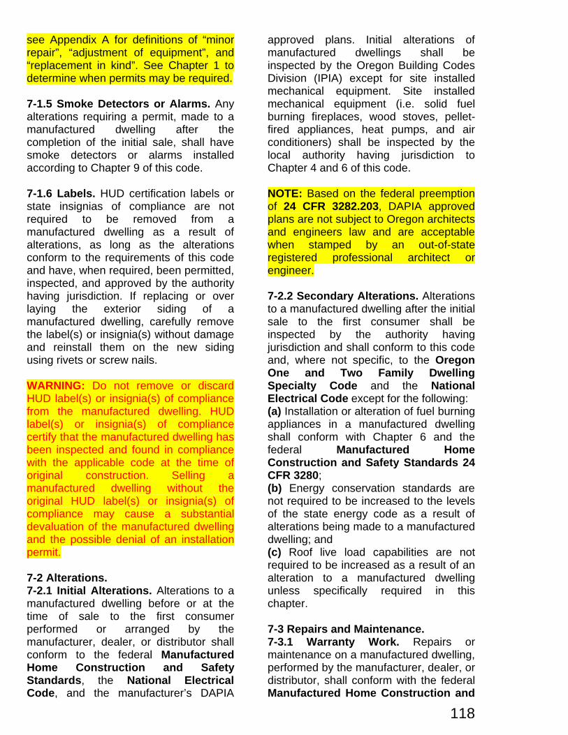
118
see Appendix A for definitions of “minorrepair”, “adjustment of equipment”, and“replacement in kind”. See Chapter 1 todetermine when permits may be required.
7-1.5 Smoke Detectors or Alarms. Anyalterations requiring a permit, made to amanufactured dwelling after thecompletion of the initial sale, shall havesmoke detectors or alarms installedaccording to Chapter 9 of this code.
7-1.6 Labels. HUD certification labels orstate insignias of compliance are notrequired to be removed from amanufactured dwelling as a result ofalterations, as long as the alterationsconform to the requirements of this codeand have, when required, been permitted,inspected, and approved by the authorityhaving jurisdiction. If replacing or overlaying the exterior siding of amanufactured dwelling, carefully removethe label(s) or insignia(s) without damageand reinstall them on the new sidingusing rivets or screw nails.
WARNING: Do not remove or discardHUD label(s) or insignia(s) of compliancefrom the manufactured dwelling. HUDlabel(s) or insignia(s) of compliancecertify that the manufactured dwelling hasbeen inspected and found in compliancewith the applicable code at the time oforiginal construction. Selling amanufactured dwelling without theoriginal HUD label(s) or insignia(s) ofcompliance may cause a substantialdevaluation of the manufactured dwellingand the possible denial of an installationpermit.
7-2 Alterations.7-2.1 Initial Alterations. Alterations to amanufactured dwelling before or at thetime of sale to the first consumerperformed or arranged by themanufacturer, dealer, or distributor shallconform to the federal ManufacturedHome Construction and SafetyStandards, the National ElectricalCode, and the manufacturer’s DAPIA
approved plans. Initial alterations ofmanufactured dwellings shall beinspected by the Oregon Building CodesDivision (IPIA) except for site installedmechanical equipment. Site installedmechanical equipment (i.e. solid fuelburning fireplaces, wood stoves, pellet-fired appliances, heat pumps, and airconditioners) shall be inspected by thelocal authority having jurisdiction toChapter 4 and 6 of this code.
NOTE: Based on the federal preemptionof 24 CFR 3282.203, DAPIA approvedplans are not subject to Oregon architectsand engineers law and are acceptablewhen stamped by an out-of-stateregistered professional architect orengineer.
7-2.2 Secondary Alterations. Alterationsto a manufactured dwelling after the initialsale to the first consumer shall beinspected by the authority havingjurisdiction and shall conform to this codeand, where not specific, to the OregonOne and Two Family DwellingSpecialty Code and the NationalElectrical Code except for the following:(a) Installation or alteration of fuel burningappliances in a manufactured dwellingshall conform with Chapter 6 and thefederal Manufactured HomeConstruction and Safety Standards 24CFR 3280;(b) Energy conservation standards arenot required to be increased to the levelsof the state energy code as a result ofalterations being made to a manufactureddwelling; and(c) Roof live load capabilities are notrequired to be increased as a result of analteration to a manufactured dwellingunless specifically required in thischapter.
7-3 Repairs and Maintenance.7-3.1 Warranty Work. Repairs ormaintenance on a manufactured dwelling,performed by the manufacturer, dealer, ordistributor, shall conform with the federalManufactured Home Construction and
119
Safety Standards, the NationalElectrical Code, and the manufacturer’sDAPIA approved plans.
7-3.2 Non-Warranty Work. Repairs andmaintenance on a manufactured dwellingby the homeowner shall conform to thefederal or state code in force at the timeof original manufacture. Maintenancework which is not exempt from permitsaccording to Section 7-1.4 of this chaptershall be inspected by the authority havingjurisdiction.
7-4 Conversion.7-4.1 Change of Occupancy.Manufactured dwellings converted to adifferent occupancy classification shallmeet the minimum code requirements ofthe appropriate specialty codes for thatspecific occupancy. Refer to ChapterTwo for more information.
7-5 Re-Roofing.7-5.1 General. Re-roofing for thepurpose of this chapter is consideredmaintenance work. If the existing roofingis being replaced with equivalent roofing,no permits are required. If the existingroofing is being replaced with a differentroofing material a permit may be requiredfrom the authority having jurisdiction. Allreplacement roofing shall be installedaccording to this code and, where notspecific, to the roofing manufacturer’sinstallation instructions, and the OregonOne and Two Family DwellingSpecialty Code.
7-5.2 Roofing Removal. Existing roofingmaterial and underlayment, shall beremoved prior to installing new roofingmaterial. Damaged or defective rafters,trusses, or sheathing shall be repaired orreplaced before installing new roofingmaterial. Replacement roofing shall notbe added over existing roofing material.
7-5.3 Roof Penetrations. All plumbingvents, mechanical vents, chimneys, fluepipes, and the electrical masthead shallbe flashed and extended through the
replacement roofing and with listed andcompatible equipment or materialaccording to the following:(a) Appliance vent extensions shall bemade according to the appliance listingand manufacturer’s installationinstructions;(b) Plumbing vents shall extend at least 6inches (15 cm) above the roof additionand shall not be located within 3 feet(0.91 meters) of any motor driven airintake that opens into habitable rooms;(c) Fireplace and wood stove chimneysand flues shall extend through the roof aminimum of 3 feet (.91 meters) and aminimum of 2 feet (.61 meters) above thehighest portion of the new roof within 10horizontal feet (3.05 meters); and(d) Electrical mastheads shall extendabove the roof at least high enough tomaintain the minimum clearancesrequired in Chapter 4 of this code.
7-5.4 Ventilation. Ventilation shall beprovided to the attic space when re-roofing a manufactured dwellingaccording to Section 806 of the OregonOne and Two Family DwellingSpecialty Code.
7-6 Roof Additions.7-6.1 Roof Loads. The roof addition shallbe designed and constructed for the roofsnow loads and wind loads specific to thearea the manufactured dwelling is sitedaccording to the requirements of thiscode, and where not specific, to theOregon One and Two Family DwellingSpecialty Code and the authority havingjurisdiction. Manufactured dwelling roofadditions added over an existing roof of amanufactured dwelling shall be supportedthrough to the ground according to thefollowing:(a) Where a roof addition conveys weighton the manufactured dwelling ridgebeam, the ridge beam shall be reinforcedor the span reduced according to anacceptable design;(b) Where a roof addition conveys weighton the exterior walls of the manufactureddwelling, the structural headers above
120
each opening shall be reinforcedaccording to an acceptable design;(c) Where a roof addition conveys weighton the existing manufactured dwellingroof trusses or rafters, the trusses orrafters shall be reinforced according to anacceptable design;(d) Where a roof addition conveys weighton the perimeter and marriage linefoundation, the foundation shall beincreased in capacity or spacingaccording to an acceptable design;(e) Roof additions shall be secured to themanufactured dwelling to prevent upliftaccording to an acceptable design;
7-7 Dormers and Gables.7-7.1 General. Roof dormers or gablesare often added over an existingmanufactured dwelling roof for thepurpose of tying in a garage, cabana, orporch roof or for aesthetic purposes only.
7-7.2 Minimum Requirements. Alldormer and gable roof additions shall beconstructed according to the following:(a) Dormer and gable roof additions shallbe constructed according to this sectionof the code, and, where not specific, tothe Oregon One and Two FamilyDwelling Specialty Code and the roofingmanufacturer’s installation instructions; or(b) Dormer and gable roof additions shallbe constructed according to this sectionof the code, the manufacturer’s DAPIAapproved plans, and the roofingmanufacturer’s installation instructions;and(c) To minimize the weight on the existingroof structure, dormers and gables shallonly be constructed with kiln dried lumberor lumber having a moisture content of 19percent or less. Alternate lightweightconstruction materials may also be usedwith prior approval from the authorityhaving jurisdiction.
7-7.3 Existing Roofing. To minimize theweight on the existing roof structure,existing roofing material shall be removedprior to installing dormer or gable roofadditions.
7-7.4 Tie-Down. Dormer and gable roofadditions shall be secured to themanufactured dwelling in such a manneras to prevent uplift and sliding accordingof this code, the manufacturer’s DAPIAapproved plans, or Oregon One andTwo Family Dwelling Specialty.
7-8 Re-Furbishing.7-8.1 General. Refurbishedmanufactured dwellings shall beinspected and be issued an insignia ofcompliance to verify it meets the codeprior to occupancy, siting, or beingoffered for rent, lease, or sale. Thissection of the code is intended forindividuals, families, or their contractors.This section of the code may be used bya government agency for the purpose ofrehabilitating low cost housing. Thissection of the code is not intended forcontractors or companies in the businessof re-building or re-manufacturingmanufactured dwellings for the purposeof rent, lease, or sale.
7-8.2 Qualifications. Manufactureddwellings may be refurbished under thefollowing circumstances:(a) The manufactured dwelling has beendetermined to be an unsafe structureaccording to the provisions in Section 1-3.1 of this code;(b) The manufactured dwelling has beenidentified as damaged or out ofcompliance with the applicable codes;(c) The manufactured dwelling has noinsignia of compliance and needsverification of code compliance for aninsurance carrier, government agency, orlending institution;(d) The manufactured dwelling has beenclassified as salvage by an insurancecompany or a government agency;(e) The manufactured dwelling has beensold “as-is” or “with-all-faults” and needsverification that it complies with theapplicable codes according to theprovisions in Section 1-3.2 of this code;(f) The manufactured dwelling has beenrefurbished, restored, or remodeled and
121
needs verification that it complies with theapplicable codes.
7-8.3 Application. Application forinspection and approval shall be made tothe Building Codes Division by letter,phone, fax, or electronic mail. Theapplication shall be made in conformancewith current Building Codes Divisionprocedures.
7-8.4 Inspections. One or moreInspections may be required to verifycompliance with the codes in effect on thedate of manufacturer. If a date is notknown, the manufactured dwelling will beinspected to the 1972 edition of ANSIA119.1 Standard for Mobile Homes andthe 1971 edition of the NationalElectrical Code NFPA 70. Where it isimpractical for the manufactured dwellingto conform to the strict letter of the code,the inspector may accept methods ormaterials that are substantially equivalentto the code. Engineering may be requiredto substantiate equivalency if structuralcomponents of the manufactured dwellinghave been altered or replaced. Requiredcorrections, if any, will be identified inwriting by the inspector. All correctionsshall be completed and re-inspected priorto final approval.
7-8.5 Approval. Once the inspections aremade and final approval is given, theinspector will attach an Oregon insignia ofcompliance to each section of themanufactured dwelling.
7-9 Substantial Equivalence to HUD.7-9.1 General. A manufactured dwellingbuilt between September 1, 1969 andJune 14, 1976 may be upgraded to besubstantially equivalent to a homeproduced in accordance with the June1976 HUD standards for such dwellings.To receive a report indicating substantialequivalence and an Oregon Insignia ofCompliance, all the following must occur:(a) Application for inspection andapproval shall be made to the Building
Codes Division in conformance withcurrent Division procedures.(b) The home must have been producedbetween September 1, 1969 and June14, 1976.(c) Battery powered or direct wired smokedetectors must be installed in eachbedroom and each hallway adjoiningbedroom areas.(d) Ground fault interrupter devices mustbe installed on exterior receptacles andbathroom outlets. Kitchens and heat tapereceptacles are exempt from thisrequirement.(e) Each bedroom must have an egresswindow. The window must have aminimum of 5 square feet openingcapacity with a horizontal opening aminimum of 20" and the vertical openinga minimum of 24". The window openingmust be within 36" of the floor.(f) All electrical systems and devicesmust operate properly and be installedproperly.(g) All plumbing systems and devicesmust operate properly and be installedproperly.(h) All mechanical systems must operateand be installed properly. Baths musthave an exhaust fan or an openablewindow. Kitchens must have amechanical exhaust fan.(i) The structure of the home must besound, with normal aging accepted. Theroof, siding, windows, and doors must notleak. There must be two exit doorsremote from each other. The home mustbe in original condition concerning thedesign.(j) Unapproved wood stoves or fireplacesmust be removed.(k) All systems in the home must operateto include doors and windows.(l) The home cannot have aluminumwiring on the individual branch circuits.(m) The furnace and water heatercompartment walls, ceiling, and allexposed wood must be fully lined with aminimum of 5/16" sheetrock, except forthe floor.(n) The bottom of the cabinets above therange and extending 6" on each side of
122
the range must be covered with aminimum of 5/16" sheetrock. Thisincludes the space between the rangehood and the bottom of the cabinet.(o) The wall behind the range andextending 6" to each side of the rangemust be covered with a minimum of 5/16"sheetrock.7-9.2 Inspections. One or moreinspections may be required to verifycompliance with the code in effect on thedate of manufacturer as well as therequired upgrades. Where it isimpractical for the manufactured dwellingto conform to the strict letter of the code,the inspector may accept methods ormaterials that are substantially equivalentto the code. Engineering may berequired to substantiate equivalency ifstructural components of themanufactured dwelling have been alteredor replaced. Required corrections, if any,will be identified in writing by theinspector. All corrections shall becompleted and reinspected prior to finalapproval.
7-9.3 Approval. Once the inspectionsare made and final approval is given, theinspector will attach an Oregon insignia ofcompliance, to each section of themanufactured dwelling and issue a reportindicating the home has been upgradedto achieve substantial equivalence to the1976 HUD Standard for such dwellings.
7-10 Re-Manufacturing.7-10.1 General. Re-manufacturedmanufactured dwellings shall beinspected and be issued an Oregoninsignia of compliance to verify themanufactured dwelling meets the codeprior to being sited or offered for rent,lease, or sale. This section of the code isintended for contractors or companies inthe business of re-building or re-manufacturing manufactured dwellings forthe purpose of renting, leasing, or sellingmanufactured dwellings. This section ofthe code is not intended for individuals orfamilies for personal home improvementsor repair.
7-10.2 Qualifications. Re-manufactureddwellings shall be inspected by theDivision and issued an Oregon insignia ofcompliance under the followingcircumstances:(a) The manufactured dwelling has beendetermined to be an unsafe structureaccording to the provisions in Section 1-3.1 of this code;(b) The manufactured dwelling has beenidentified as damaged or out ofcompliance with the applicable codes;(c) The manufactured dwelling has noinsignia of compliance and has no way ofproving it complies with the applicablecodes;(d) The manufactured dwelling has beenclassified as salvage by an insurancecompany or a government agency;(e) The manufactured dwelling has beensold “as-is” or “with-all-faults” and needsverification that it complies with theapplicable codes according to theprovisions in Section 1-3.2 of this code;(f) The manufactured dwelling has beenrefurbished, restored, or remodeled andneeds verification that it complies with theapplicable codes.
7-10.3 Requirements. Persons re-manufacturing manufactured dwellingsshall comply with the following:(a) Shall be licensed by the ConstructionContractors Board;(b) Shall be registered with the BuildingCodes Division as a manufactureraccording to OAR 918-500-0300;(c) Shall be in compliance with ORS 316,656, 657, and 701.
7-10.4 Application. After meeting theminimum requirements in Section 7-10.3of this code, application for inspectionand approval shall be made to theBuilding Codes Division by telephone,letter, fax, or electronic mail. Applicationshall be made in conformance withcurrent Building Codes Divisionprocedures.
123
7-10.5 Inspections. One or moreInspections may be required to verifycompliance with the codes in effect on thedate of manufacturer. If a date is notknown, the manufactured dwelling will beinspected to the 1972 edition of ANSIA119.1 Standard for Mobile Homes andthe 1971 edition of the NationalElectrical Code NFPA 70. Where it isimpractical for the manufactured dwellingto conform to the strict letter of the code,the inspector may accept methods ormaterials that are substantially equivalentto the code. Engineering may be requiredto substantiate equivalency if structuralcomponents of the manufactured dwellinghave been altered or replaced. Requiredcorrections, if any, will be identified inwriting by the inspector. All correctionsshall be completed and re-inspected priorto final approval.
7-10.6 Approval. Once the inspectionsare made and final approval is given, theinspector will assure a valid insignia ofcompliance is affixed to each section ofthe manufactured dwelling.
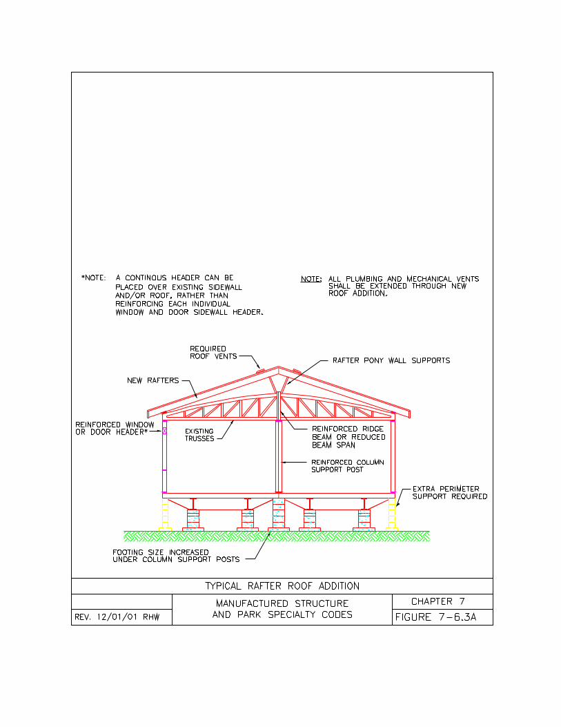
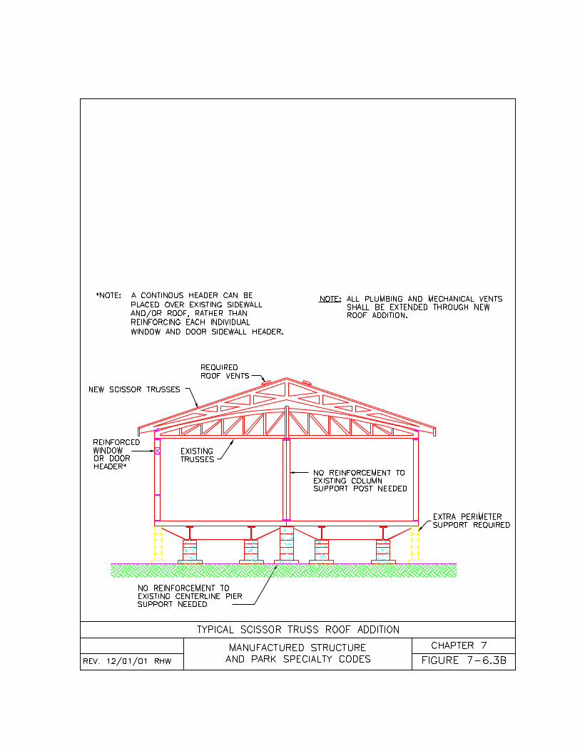
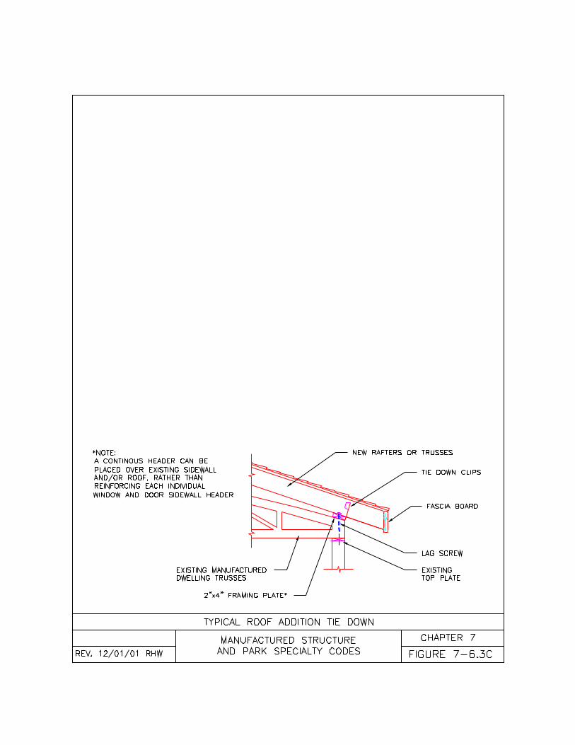
125
CHAPTER EIGHTACCESSORY BUILDINGS ANDSTRUCTURES
8-1 General8-2 Awnings and Carports8-3 Cabanas8-4 Garages8-5 Ramadas8-6 Basements
8-1 General.8-1.1 Accessory Buildings andStructures. This chapter of the code isintended to supplement the structuralrequirements of Oregon One and TwoFamily Dwelling Specialty Code, but isnot intended to take its place.(a) Wherever the requirements of thiscode differ from the Oregon One andTwo Family Dwelling Specialty Code,this code shall apply;(b) Alternate materials used in theconstruction of accessory buildings orstructures permitted in the Oregon Oneand Two Family Dwelling SpecialtyCode, but not mentioned in this code maybe permitted if acceptable to the authorityhaving jurisdiction;(c) Alterations made to a manufactureddwelling to accommodate an accessorybuilding or structure shall conform withChapter 7 of this code;(d) The addition of an accessory buildingor structure shall not eliminate requiredwindows, doors, or ventilation in amanufactured dwelling.
8-2 Awnings and Carports.8-2.1 General. Carports and awningsshall be constructed as accessorystructures to a manufactured dwellinglocated on the same lot according to thissection.(a) Awnings and carports shall bedesigned for the site specific vertical andhorizontal loads according to the OregonOne and Two Family DwellingSpecialty Code;
(b) Awnings and carports shall be locatedon a lot according to the restrictions ofChapter 9 of this code;(c) Awnings and carports shall not restrictthe required egress openings in amanufactured dwelling;(d) Awnings and carports shall not restrictthe required egress path from amanufactured dwelling;(e) Manufactured dwelling windows anddoors may open directly into a spaceoccupied by a permanent or rigid awningor carport;(f) Awnings and carports may be built asprefabricated or site built according to thissection of the code;(g) Notwithstanding any other code,awnings may be used as carports;(h) Notwithstanding any other code, exitdoors and egress windows may open intothe area covered by an awning or carport;
8-2.2 Enclosures. Awnings and carportsenclosures shall comply with this section.(a) Awnings and carports may only beenclosed on a maximum of two sidesincluding the side adjoining themanufactured dwelling;(b) Awnings and carports shall have twosides open to provide free flowingventilation but may be enclosed withinsect screening or other materialsallowing the free passage of air;(c) Manufactured dwelling windows anddoors may open directly into a spaceoccupied by a permanent or rigid awningor carport; and(d) If an awning or carport is enclosed onmore than 2 sides, it shall meet therequirements of an attached garage or acabana according to this chapter.
8-2.3 Site Built Awnings and Carports.Site built awnings and carports shall beconstructed, anchored, and supportedaccording to the requirements of thiscode and, where not specific, to theOregon One and Two Family DwellingSpecialty Code for patio covers.(a) Site built awnings and carports shallbe self supported, free standingstructures;
126
(b) Site built awnings and carports shallnot be supported by or bear any weighton a manufactured dwelling;(c) Site built awnings and carports maybe attached to a manufactured dwellingonly with flashing, roofing materials, orother sealing materials to provide aweather seal; and(d) Site built awnings and carports shallbe constructed according to plansapproved by the authority havingjurisdiction and this code.
8-2.4.1 Prefabricated Awnings andCarports. Prefabricated awning andcarports shall be constructed, anchored,and supported according to therequirements of this code and, where notspecific, to the Oregon One and TwoFamily Dwelling Specialty Code forpatio covers.(a) Prefabricated awnings and carportsmay be self supporting, free standingstructures or may be supported in part bythe manufactured dwelling;(b) Prefabricated awnings and carportssupported in part by a manufactureddwelling shall be attached according tothis code;(c) Prefabricated awnings and carportsshall be constructed according to plansapproved by the authority havingjurisdiction and this code. Where theprefabricated awning or carport is a listedand labeled product, the manufacturer’sinstallation instructions may be accepted.
8-2.4.2 Wall Support. Prefabricatedawnings and carports, when supported bythe manufactured dwelling exterior wallshall be attached according to thissection.(a) Prefabricated awnings and carportsroofs shall be supported by a horizontalrail attached with a minimum ¼-inch (6mm) lag screw or equal having aminimum 1-1/2-inch (3.75 cm) penetrationinto each exterior wall stud in the area ofattachment;(b) Prefabricated awnings and carportroofs shall be supported by the horizontalrail and attached according to the
approved plans or approvedmanufacturer’s installation instructions;and(c) Prefabricated awnings and carportsshall not be supported by or secured tothe top plate of the manufactureddwelling’s exterior wall.
8-2.4.3 Roof Support. Prefabricatedawnings and carports, when supported bythe manufactured dwelling roof rafter,truss, fascia, or eave shall be attachedaccording to this section.(a) Prefabricated awnings and carportsshall only be attached to a manufactureddwelling roof when specifically permittedby the engineered DAPIA approvedplans;(b) Prefabricated awnings and carportsshall only be attached to a manufactureddwelling roof when the engineered DAPIAapproved plans demonstrate themanufactured dwelling roof wasengineered and constructed to carry theadditional live loads, dead loads, anduplift loads imposed by an attachedawning or carport;(c) Prefabricated awnings and carportsshall only be attached to a manufactureddwelling roof according to the approveddetails provided in the engineered DAPIAapproved plans; and(d) DAPIA approved plans shall be madeavailable to the authority havingjurisdiction prior to attaching any awningor carport to a manufactured dwelling roofrafter, truss, eave or fascia.
8-2.4.4 Foundation Support.Prefabricated awnings and carports shallbe supported and anchored according tothis section.(a) Manufactured dwellings supportingprefabricated awnings and carports onthe roof or exterior wall shall have extraperimeter foundation support in that areaconsisting of one-half spaced perimeterblocking unless the home is supported onand attached to a foundation wall orbasement wall; and(b) The free standing, self supportingportion of a prefabricated awning and
127
carport shall be supported and anchoredto the ground, deck, or slab according tothe approved plans or the manufacturer’sinstallation instructions.
8-3 Cabanas.8-3.1 Specifications. Cabanas shall beconstructed as accessory buildings forthe purpose of increasing the gross floorarea of a manufactured dwelling whenlocated on the same lot. Cabanas shallbe constructed according to this section:(a) Site built cabanas shall be designedfor the site specific vertical and horizontalloads according to the Oregon One andTwo Family Dwelling Specialty Code;(b) Cabanas shall be located on a lotaccording to the restrictions of Chapter 9of this code;(c) Cabanas shall be designed andconstructed as freestanding, selfsupporting structures, supported andanchored according the Oregon One andTwo Family Dwelling Specialty Codefor single family dwellings;(d) Cabanas shall not be supported by ortransfer any vertical or horizontal loads toa manufactured dwelling;(e) Cabanas shall be constructedaccording to the plans approved by theauthority having jurisdiction;(f) Cabanas may be site built orprefabricated according to this section ofthe code;(g) Manufactured dwellings may be usedas cabanas to other manufactureddwellings if not constructed to create aduplex;(h) Alterations to a manufactured dwellingresulting from a cabana addition shallcomply with Chapter 7 of this code.
8-3.2 Attachments. Cabanas shall beattached to manufactured dwellingsaccording to the following:(a) When a manufactured dwelling issupported only on piers the, cabana shallbe attached to a manufactured dwellingonly with flashing, roofing material, orother sealing materials to provide aweather seal; or
(b) When a manufactured dwelling andcabana are both supported and securedto a foundation wall or basement wall, thecabana may be permanently attached tothe manufactured dwelling according tothe requirements in Chapter 3 formarriage line connections.
8-3.3 Access and Egress. Manufactureddwelling access and egress shall bemaintained when a cabana is attached toa manufactured dwelling according to thefollowing:(a) Cabanas shall not restrict the requiredpath of egress on the exterior of amanufactured dwelling;(b) Cabanas shall not restrict access toan appliance or utility connections;(c) Cabanas shall not eliminate the pathof egress within a manufactured dwelling;(d) When a cabana is expanding the areaof a bedroom an egress window or doorshall be maintained;(e) When a cabana encloses a requiredexit door, an additional exit door shall beinstalled in the cabana to provide a safeexit out of both structures;(f) There shall not be any locks on interiordoors within the egress path of themanufactured dwelling;(g) Alternate egress windows or exitdoors shall be subject to approval by theauthority having jurisdiction; and(h) One of the manufactured dwelling exitdoors must open directly to the outsidewithout passing through a cabana,garage, or any other accessory building.
8-3.4 Site Built Cabanas. Site builtcabanas shall be constructed, attached,anchored, and supported according toplans approved by the authority havingjurisdiction based on the requirements ofthe Oregon One and Two FamilyDwelling Specialty Code for a single-family dwelling.
8-3.5 Prefabricated Cabanas. Cabanasconstructed off site shall comply with therules for construction of prefabricatedstructures as provided in OAR 918-674-
128
0005 through 0155 and bear an OregonInsignia of Compliance.(a) Prefabricated cabanas shall beconstructed and attached according toDivision approved plans based on therequirements of the Oregon One andTwo Family Dwelling Specialty Codefor a single-family dwellings; and(b) Prefabricated cabanas shall besupported and anchored according toplans approved by the authority havingjurisdiction based on the requirements ofthe Oregon One and Two FamilyDwelling Specialty Code for a single-family dwelling.
8-4 Garages.8-4.1 Specifications. An attachedgarage shall be constructed as anaccessory building to a manufactureddwelling located on the same lot.Garages shall be constructed accordingto this section:(a) Garages shall be designed for the sitespecific vertical and horizontal loadsaccording to the Oregon One and TwoFamily Dwelling Specialty Code;(b) Garages shall be located on a lotaccording to the restrictions of Chapter 9of this code;(c) Garages shall be designed andconstructed as freestanding, selfsupporting structures supported andanchored according the Oregon One andTwo Family Dwelling Specialty Code;(d) Garages shall not be supported by ortransfer any vertical or horizontal loads toa manufactured dwelling or cabana;(e) Garages shall be constructedaccording to the plans approved by theauthority having jurisdiction; and(f) Alterations to a manufactured dwellingresulting from the addition of an attachedgarage shall comply with Chapter 7 of thiscode.
8-4.2 Attachments. Garages shall beattached to a manufactured dwellingaccording to the following:(a) When a manufactured dwelling issupported only on piers, the garage shallbe attached to the manufactured dwelling
only with flashing, roofing material, orother sealing materials to provide aweather seal; or(b) When a manufactured dwelling issupported and secured to a foundationwall or basement wall, the garage may bepermanently attached to themanufactured dwelling according to therequirements in Chapter 3 for marriageline connections.
8-4.3 Access and Egress. Manufactureddwelling access and egress shall bemaintained when a garage is attached toa manufactured dwelling according to thissection:(a) Garages shall not restrict the requiredpath of egress on the exterior of amanufactured dwelling;(b) Garages shall not restrict appliance orutility accesses;(c) Garages shall not eliminate the pathof egress within a manufactured dwelling;(d) Garages shall not be placed wherethe bedroom egress window is blockedunless there is a second egress windowavailable or installed in the samebedroom to provide a safe exit out of theaffected bedroom in an approvedmanner;(e) When a garage encloses a requiredexit door, an additional exit door (notvehicle door) shall be installed in thegarage to provide a safe exit out of bothstructures;(f) No hinged exterior egress door shallbe prevented from opening at least 90degrees;(g) Alternate egress windows or exitdoors shall be subject to approval by theauthority having jurisdiction; and(h) One of the manufactured dwelling exitdoors must open directly to the outsidewithout passing through a garage,cabana, or any other accessory building.
8-4.4 Separation. Attached garages shallbe separated from the manufactureddwelling or cabana according to thefollowing requirements:
129
(a) A manufactured dwelling or cabanashall not have any opening from asleeping area into a garage;(b) A manufactured dwelling or cabanashall not have any windows opening intoa garage;(c) A manufactured dwelling or cabanadoor entering a garage shall have noglass and be constructed of one of thefollowing:1. A solid wood door not less than 1-3/8inches (3.49 cm) in thickness;2. A 20 minute or higher fire rated door;or3. An insulated metal exterior door.(d) A garage shall be completelyseparated from the manufactureddwelling or cabana (including the atticand crawl space areas) with 1/2 inch (38mm) gypsum board or equivalent fireresistive construction on the garage side.Mud and tape is not required at the joints.
8-5 Ramadas.8-5.1 Accessory. A ramada shall beconstructed as an accessory structure toa manufactured dwelling located on thesame lot. Ramadas shall be constructedaccording to this section:(a) A ramada shall be designed andconstructed as a freestanding, selfsupporting structure meeting therequirements of this code and, where notspecific, to the Oregon One and TwoFamily Dwelling Specialty Code;(b) A ramada shall be designed for thesite specific vertical and horizontal loadsaccording to the Oregon One and TwoFamily Dwelling Specialty Code;(c) Ramadas shall not be supported by ortransfer any vertical or horizontal loads toa manufactured dwelling or cabana;(d) A ramada shall not be whollyenclosed on the sides or ends;(e) A ramada may be extended past themanufactured dwelling to provide anawning or carport area under the sameroof;(f) Ramadas built over a cabana shall besubject to the same requirements as if thestructure was a manufactured dwelling;
(g) Ramadas shall provide a minimumclearance of not less than 18 inches (46cm) vertically above the highest portion ofa manufactured dwelling or cabana roof;(h) Ramadas shall provide a minimumclearance of not less than 6 inches (15cm) horizontally on either side of amanufactured dwelling or cabana; and(i) Ramadas shall not have anypermanent cross bracing, architecturalappurtenances, or structural ties thatwould obstruct the installation or removalof any manufactured dwelling or cabana.
8-5.2 Access and Egress. Manufactureddwelling access and egress shall bemaintained when a ramada is constructedover a manufactured dwelling accordingto this section, and ramadas:(a) Shall not restrict the required path ofegress on the interior or exterior of amanufactured dwelling or cabana;(b) Shall not restrict appliance or utilityaccesses;(c) Shall not restrict a hinged exit doorfrom opening at least 90 degrees; and(d) Shall not block a bedroom egresswindow opening.
8-5.3 Roof Construction. Ramada roofsshall be constructed according to thefollowing:(a) Each ramada roof shall be ventilatedwith a minimum of one 28 square inch(181 square centimeter) vent locatedalong the ridge of the ramada roof at 10feet (3.05 meters) on center;(b) Chimneys or flues from solid fuelburning appliances shall extend at least 3feet (0.91 meters) above the ramada roofpenetration and at least 2 feet (0.61meters) above the highest elevation ofthe ramada roof within 10 feet horizontal(3.05 meters) of the chimney;(c) Vents for fuel burning appliances shallextend through the ramada roofaccording to the listing of the appliance;(d) Plumbing vents shall extend throughthe ramada roof a minimum of 6 inches(15 cm) above the flashing and shall notbe located within 3 feet (0.91 meters) of
130
any motor driven air intake that opensinto habitable rooms;(e) Appliance vent extensions shall bemade according to the appliance listingand manufacturer’s installationinstructions;(f) Overhead electrical mastheads shallnot be permitted on a manufactureddwelling or cabana located under aramada;(g) All plumbing vents, mechanical vents,chimneys, and flue pipes shall be flashedand extended through the dormer orgable roof addition with listed andcompatible equipment or material; and(h) Appliance vent extensions shall bemade according to the appliance listingand manufacturer’s installationinstructions.
8-6 Basements.8-6.1 Specifications. Basements shallbe constructed as an accessory buildingto a manufactured dwelling located on thesame lot according to this section:(a) Basements shall be designed for theappropriate vertical and horizontal loadsrequired for the site on which it is located;(b) Basements shall be designed tosupport the live and dead loads of themanufactured dwelling;(c) Basements shall be constructedaccording to Chapter 3 and, where notspecific, to the Oregon One and TwoFamily Dwelling Specialty Code;(d) Basements may use the transversefloor joists of a manufactured dwelling topartially resist the horizontal pressuresagainst the basement wall below thesidewalls;(e) Basements shall not use thelongitudinal floor joists of a manufactureddwelling to resist any horizontal pressuresagainst the basement walls below theendwalls;(f) Basements shall be engineered by anOregon licensed and registered engineeror architect;(g) Basements shall be accessible frominside the manufactured dwelling or fromthe exterior;
(h) Basements shall have smoke alarmsor detectors according to Chapter 9 ofthis code;(i) Basements may include a garage, orstorage area if the underside of themanufactured dwelling is protected with½ inch (12.7 mm) gypsum board orequivalent fire resistive construction.
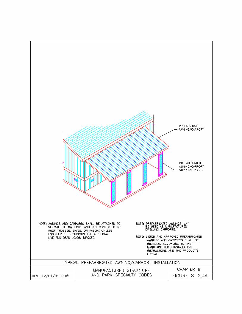
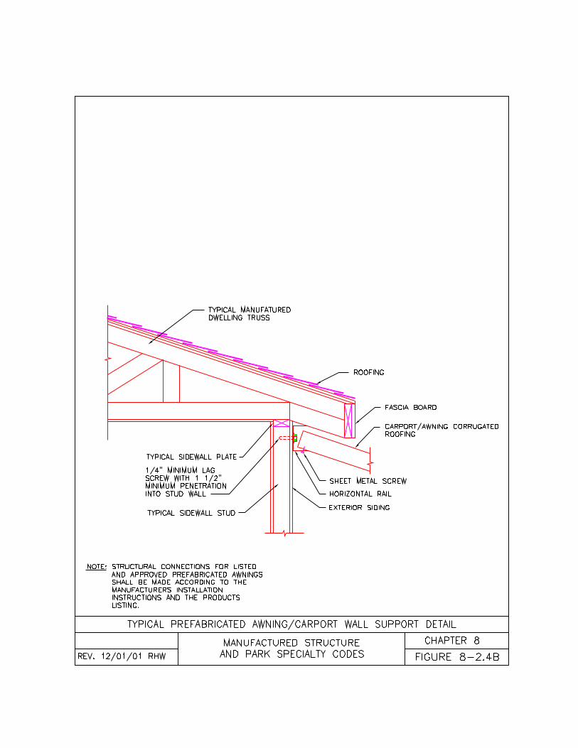
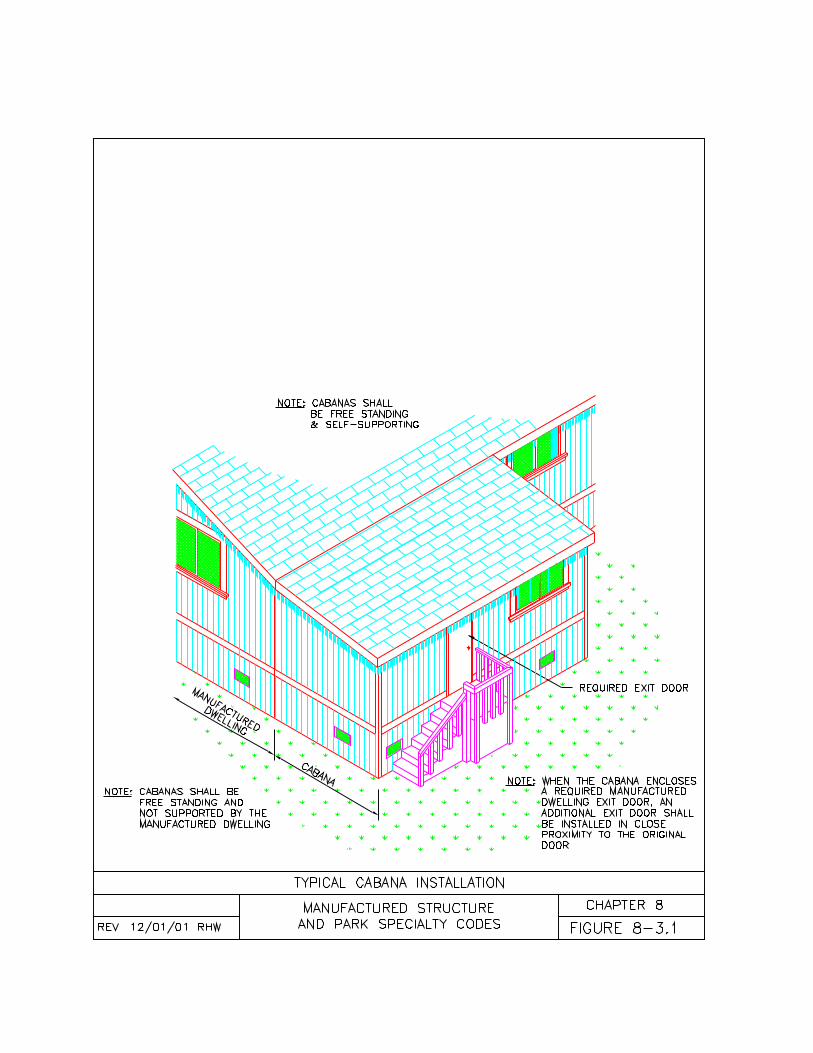
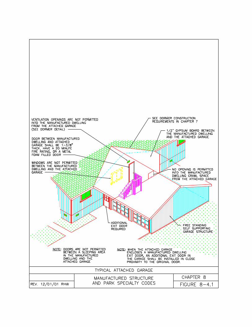
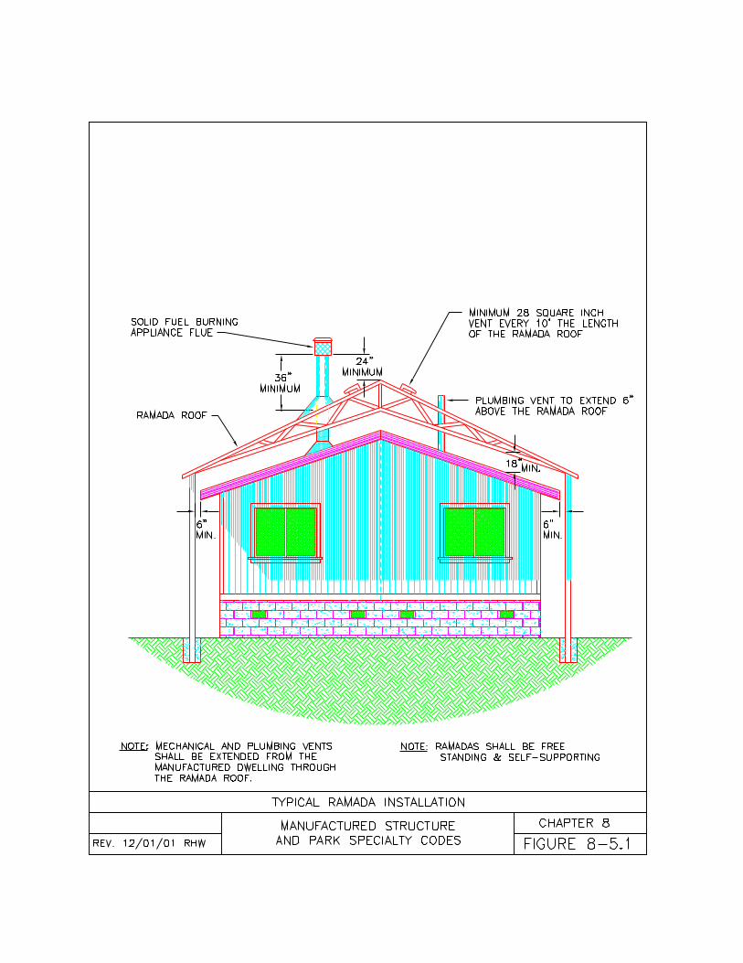
131
CHAPTER NINEFIRE AND LIFE SAFETY
9-1 General9-2 Fire Warning Equipment9-3 Extinguishing Systems9-4 Emergency Egress Path9-5 Fire Separation Inside Parks9-6 Fire Separation Outside Parks9-7 Fire Separation Requirements9-8 Wildfire Hazard Mitigation
9-1General9-1.1 Application. Each manufactureddwelling, accessory building, andaccessory structure shall be sited andinstalled to the minimum fire, and lifesafety requirements of this chapter. Thischapter applies to manufactured dwellinginstallers, contractors, homeowners, andpark owners siting or installingmanufactured dwellings, accessorybuildings, or accessory structures.
9-2 Fire Warning Equipment9-2.1 Initial Sale of New Homes. At thetime of initial sale and installation, a newmanufactured dwelling shall haveoperating smoke alarms installedcomplying with the federal ManufacturedHome Construction and SafetyStandards, 24 CFR 3280.208.
9-2.2 After Initial Sale of New Home.After the initial sale or installation, amanufactured dwelling shall haveapproved operating smoke alarmsinstalled according to this chapter ifrequired by the following:(a) When a manufactured dwelling isrelocated to or within a manufactureddwelling park, mobile home park, orcombination park, as required by ORS90.740(4)(d);(b) When a manufactured dwelling isbeing altered or repaired to the degreethat a permit is required;(c) When a manufactured dwelling isbeing installed on a site as a secondaryinstallation;
(d) When a manufactured dwelling isbeing sold or offered for sale, as requiredby ORS 479.260(2);(e) When a manufactured dwelling isbeing rented, leased, or offered for rent orlease, as required by ORS 479.270;(f) When a manufactured dwelling isbeing re-manufactured or refurbished;(g) When a visual inspection is beingperformed on a manufactured dwelling bythe Division; and(h) Prior to an Oregon insignia ofcompliance being issued by the Division.
9-2.3 Standard. Smoke alarms installedin manufactured dwellings, basements, orcabanas shall be listed and labeled asconforming with the requirements of UL217 or ANSI/UL 268. Visible signalingappliances installed in manufactureddwellings, basements, or cabanas shallbe listed and labeled as conforming to therequirements of ANSI/UL 1971. Smokealarms in manufactured dwellings,basements, or cabanas shall be installedin accordance with the manufacturer’slisting, the manufacturer’s installationinstructions, and this chapter. As analternate to the manufacturer’s listing andinstallation instructions smoke alarmsmay be installed in accordance withNFPA 72.
9-2.4 Smoke Alarm Locations. Smokealarms shall be located in areas wherethe ambient conditions are within thelimits specified by the manufacturer of thedevice and according to the following:(a) A single station smoke alarm shall beinstalled between the kitchen, living, ordining areas and each bedroom;(b) A single station smoke alarm shall beinstalled outside each sleeping area;(c) A single station smoke alarm shall beinstalled inside each bedroom;(d) Smoke alarms shall be installedaccording to the listing;(e) A multiple station smoke alarm shallbe installed on each additional level(basement, loft, or second story) of amanufactured dwelling;
132
(f) A smoke alarm shall be located on thebasement ceiling near the entry to astairway leading up from a basement intoa manufactured dwelling;(g) A multiple station smoke alarm shallbe installed in a manufactured dwellingbasement and interconnected with atleast one smoke alarm inside themanufactured dwelling;(h) Smoke alarms shall not be installedwithin 3 feet (91 cm) horizontally from thesupply or return air grill of a forced airheating or cooling system.
9-2.5 Power Supply. Smoke alarms shallreceive their primary power from one ofthe following sources:(a) An alternating current power source,along with a secondary battery sourcecapable of operating the device when theprimary power is interrupted; or(b) Battery operated.
9-2.6 Power Source. Smoke alarms thatreceive primary power from a 120-voltelectrical circuit shall be mounted on anelectrical outlet box and connected by apermanent wiring method in accordancewith NFPA 70-99. There shall be noswitches in the circuit between smokealarms and the over current protectivedevice of that circuit. Smoke alarms shallnot receive their power from a circuit thatis protected by a ground-fault circuit-interrupter.
9-2.7 Testing and Maintenance. Smokealarms shall be functionally tested by theinstaller in accordance with themanufacturer’s instructions to assureproper operation.
9-3 Extinguishing Systems9-3.1 When Needed. Fire sprinklersystems are not required by this code but,if installed in a manufactured dwelling,shall be installed according to thischapter. The authority having jurisdictionmay accept the installation of approvedfire sprinkler systems as an alternative tothe local fire flow requirements. Theauthority having jurisdiction shall not
require a manufactured dwelling to haveany greater fire flow requirements thanthose required for all other single familydetached homes in the same underlyingzone.
9-3.2 Standard. If fire sprinkler systemsare added to a manufactured dwelling,either at the place of manufacture or asan on site retrofit, the system shall bedesigned, installed, and tested accordingto NFPA 13D-99. Where the authorityhaving jurisdiction approves an alternatesystem, it shall be designed, installed,and tested according to NFPA 13-99.
9-3.3.1 Factory Installed. Manufacturersinstalling fire sprinkler systems shallcomply with the following minimumrequirements:(a) The fire sprinkler system shall bedesigned to operate at water pressuresequivalent to that required to supply thepotable water system within themanufactured dwelling;(b) On multiple section manufactureddwelling, the fire sprinkler system shall beequipped with couplings at the marriageline(s).(c) Upon completion of the installation,the manufacturer shall successfullycomplete a test of the fire sprinklersystem at the plant according to NFPA13-D-99 and the DAPIA approved qualityassurance manual; and(d) Upon completion of the test, themanufacturer shall fill out all applicableinformation on the NFPA ResidentialFire Sprinkler System Certification andInformation form (Figure 3-10.3 ofNFPA 501-01) or equivalent andpermanently post the certificate inside themanufactured dwelling in a locationwhere it will not likely be removed.
9-3.3.2 Factory Information. Homemanufacturers installing fire sprinklersystems shall provide specific DAPIAapproved instructions indicating thefollowing:(a) The minimum operating waterpressure in pounds per square inch (psi)
133
and the minimum operating flow rate ingallons per minute (gpm) required tosupply the system;(b) Detailed instructions on all fieldconnections required to make the systemoperable;(c) Detailed instructions on how to testthe fire sprinkler system after themanufactured dwelling is sited and allconnections have been made; and(d) Detailed instruction on the properoperation, maintenance, and periodictesting of the fire sprinkler system.
9-3.4 Site Responsibilities. When amanufactured dwelling is sited thatcontains a factory installed fire sprinklersystem, the person making the firesprinkler system connections shall beresponsible for the following:(a) Making all connections to the systemaccording to the manufacturer’sinstructions;(b) Having all connections inspected andthe system tested for leaks by the personmaking the connection;(c) Filling out the remaining portion of theNFPA Residential Fire SprinklerSystem Certification and Informationform (Figure 3-10.3 of NFPA 501-01) orequivalent permanently posted inside themanufactured dwelling; and(d) Leaving the manufacturer’s operating,maintenance, and testing instructions forthe homeowner.
9-3.5 Field Installed. When a contractorinstalls a fire sprinkler system in amanufactured dwelling on site, thecontractor shall install it according to thefollowing:(a) The contractor shall obtain a permitfrom the authority having jurisdiction forthe installation;(b) The fire sprinkler system shall bedesigned to operate on available waterpressure and supplies;(c) On multiple section manufactureddwelling, the fire sprinkler system shallhave couplings installed at the marriageline(s) to enable future relocations;
(d) Upon completion of the installation,the contractor shall successfully completea test of the fire sprinkler systemaccording to NFPA 13-D-99;(e) The contractor shall have theinstallation inspected and the testwitnessed by the authority havingjurisdiction;(f) Upon completion of the test, thecontractor shall leave detailed instructionsfor the consumer on the proper operation,maintenance, and periodic testing of thefire sprinkler system; and(g) The contractor shall fill out an NFPAResidential Fire Sprinkler SystemCertification and Information form(Figure 3-10.3 of NFPA 501-01) orequivalent and permanently post thecertificate inside the manufactureddwelling in a location where it will notlikely be removed.
9-4 Emergency Egress Path9-4.1 When Required. Eachmanufactured dwelling installed in a park,subdivision, on private or public lands,used for residential or non-residentialpurposes, shall have a clear path ofegress from each exit door and eachbedroom egress window.
9-4.2 Size. Each path of egress shall be aminimum of 3 feet (0.91 meters) in widthand exit without obstruction to a street,alley, yard, or area that can provide asafe sanctuary during an evacuation.Gates and doors in the path of egressmay be locked if they can be readilyopened from the direction of egresswithout the use of a key, device, orspecial effort or knowledge.
9-4.3 Obstructions. All egress doors andwindows shall be readily openable fromthe side from which egress is to be made,without the use of a key or special effortor knowledge. No dealer, installer, orcontractor shall alter the manufacturer’segress provisions except wherespecifically permitted in this code. Bars,grill, screens, or other obstructions placedover egress doors or windows shall be
134
releasable or removable from the insidewithout the use of a key or tool.
9-5 Fire Separation in Parks9-5.1 Setbacks and Clearances. Thissection establishes the minimumsetbacks and clearances for all structureswithin a manufactured dwelling park,mobile home park, or combination park(see Table 9-A). No municipality shallestablish more or less restrictive setbacksor clearances within manufactureddwelling parks, mobile home parks, orcombination parks except as specificallypermitted in Section 9-5.3 of this chapter.The local planning department may havecertain other restrictions as permitted inSection 10-2 of this code..9-5.2 Minimum Fire Separation. Eachstructure within a manufactured dwellingpark, mobile home park, or combinationpark shall maintain the minimumdistances to other structures specified inTable 9-A of this Chapter. See Figure 9-5.1A)
9-5.3 Alternate Setbacks andClearances. The minimum clearancesand setbacks specified in Table 9-A ofthis Chapter may be further reducedaccording to the following:(a) Accessory buildings under 120 squarefeet ( square meters) may be builtintegral to a carport or awning;(b) Accessory buildings under 120 squarefeet ( square meters) may have azero clearance to the manufactureddwelling or cabana served if a one-hourfire separation wall is provided betweenthe accessory building and themanufactured dwelling;(c) Porches, decks, steps, and landingsmay be built integral to a carport orawning;(d) A double carport serving twomanufactured dwellings shall have aminimum clearance of 3 feet (0.91meters) from each manufactured dwellingor cabana served (see Figure 9-5.3A) ora 0 foot clearance to each manufactureddwelling or cabana served if a one-hour
fire separation wall is provided throughthe center of the double carport (seeFigure 9-5.3B);(e) A double garage serving twomanufactured dwellings shall have aminimum clearance of 6 feet (1.83meters) from each manufactured dwellingor cabana served (see Figure 9-5.3C) ora 3 foot (0.91 meters) clearance to eachmanufactured dwelling or cabana servedif a one-hour fire separation wall isprovided through the center of the doublegarage (see Figure 9-5.3D);(f) A double garage serving twomanufactured dwellings may have a zeroclearance to each manufactured dwellingor cabana served if a one-hour fireseparation wall is provided between thegarage and each manufactured dwellingor cabana served (see Figure 9-5.3E) orif a one-hour fire separation wall isprovided through the center of the doublegarage and a fire separation wall isprovided between the garage andmanufactured dwelling or cabanaaccording to the minimum requirementsset forth in Chapter 8 (see Figure 9-5.3F);(g) A garage serving only onemanufactured dwelling may have a zeroclearance to the manufactured dwelling orcabana if a fire separation wall isprovided between the garage and themanufactured dwelling or cabanaaccording to the minimum requirementsset forth in Chapter 8 (see Figure 8-4.1);(h) No more than two manufactureddwellings shall be adjoined through acommon garage or carport; and(i) Manufactured dwellings shall not beadjoined through a common cabana,storage shed, barn, awning, ramada, orany other structure not specificallypermitted in this code.(j) Two or more manufactured dwellingsmay be joined together to enlarge thetotal gross floor area of a manufactureddwelling if it remains a single familydwelling and is attached according toChapter 7 of this code;(k) The authority having jurisdiction mayapprove the further reduction of required
135
setbacks and clearances when fireresistive construction is provided betweenthe structures according to theprescriptive requirements in the OregonOne and Two Family DwellingSpecialty Code. This does not includethe clearances between manufactureddwellings on adjacent lots or betweenmanufactured dwellings and propertylines.
9-5.4 Measuring Setbacks andClearances. The setbacks andclearances required in this chapter shallbe measured to the exterior walls of thestructures and do not include eaveoverhangs except for awnings andcarports.
9-6 Fire Separation Outside Parks.9-6.1 Setbacks and Clearances. Thissection establishes the minimumsetbacks and clearances formanufactured dwellings and associatedaccessory structures and accessorybuildings outside a manufactured dwellingpark, mobile home park, or combinationpark. A municipality may establish theirown setbacks and clearances or mayadopt this section by reference formanufactured dwellings located outsidemanufactured dwelling parks, mobilehome parks, or combination parks.
9-6.2 Minimum Fire Separation. Where amunicipality does not have ordinancesgoverning the setbacks and clearances ofstructures within a subdivision or on privateor public land outside a manufactureddwelling park, mobile home park, orcombination park, the minimum distancesidentified in Table 9-B of this Chaptershall be maintained:
9-6.3 Alternate Setbacks andClearances. The minimum clearancesand setbacks specified in Table 9-B ofthis Chapter may be further reducedaccording to the following:(a) Accessory buildings under 120 squarefeet (11 square meters) may be builtintegral to a carport or awning;
(b) Accessory buildings under 120 squarefeet (11 square meters) may have a zeroclearance to the manufactured dwelling orcabana served if a one-hour fireseparation wall is provided between theaccessory building and the manufactureddwelling;(c) Porches, decks, steps, and landingsmay be built integral to a carport orawning;(d) A double carport serving twomanufactured dwellings shall have aminimum clearance of 3 feet (0.91meters) from each manufactured dwellingor cabana served (see Figure 9-5.3A) ora 0 foot clearance to each manufactureddwelling or cabana served if a one-hourfire separation wall is provided throughthe center of the double carport (seeFigure 9-5.3B);(e) A double garage serving twomanufactured dwellings shall have aminimum clearance of 6 feet (1.83meters) from each manufactured dwellingor cabana served (see Figure 9-5.3C) ora 3 foot (0.91 meters) clearance to eachmanufactured dwelling or cabana servedif a one-hour fire separation wall isprovided through the center of the doublegarage (see Figure 9-5.3D);(f) A double garage serving twomanufactured dwellings may have a zeroclearance to each manufactured dwellingor cabana served if a one-hour fireseparation wall is provided between thegarage and each manufactured dwellingor cabana served (see Figure 9-5.3E) orif a one-hour fire separation wall isprovided through the center of the doublegarage and a fire separation wall isprovided between the garage andmanufactured dwelling or cabanaaccording to the minimum requirementsset forth in Chapter 8 (see Figure 9-5.3F);(g) A garages serving only onemanufactured dwelling may have a zeroclearance to the manufactured dwelling orcabana if a fire separation wall isprovided between the garage and themanufactured dwelling or cabana
136
according to the minimum requirementsset forth in Chapter 8 (see Figure 8-4.1);(h) A double carport serving twomanufactured dwellings may have a zeroclearance to each manufactured dwelling;(i) No more than two manufactureddwellings shall be adjoined through acommon garage, carport, or awning; and(j) Manufactured dwellings shall not beadjoined through a common cabana,storage shed, barn, ramada, or any otherstructure not specifically permitted in thiscode.(k) Two manufactured dwellings may beadjoined with a zero clearance if a onehour fire separation wall is providedbetween each dwelling according to theOregon One and Two Family DwellingSpecialty Code and the dwellings meetthe requirements of Chapter 2 of thiscode;(l) Up to 6 manufactured dwellings maybe adjoined with a zero clearance if atwo-hour fire separation wall is providedbetween each dwelling according to theOregon Structural Specialty Code andthe dwellings meet the requirements ofChapter 2 (see Figure 9-7.1);(m) Two or more manufactured dwellingsmay be joined together to enlarge thetotal gross floor area of a manufactureddwelling if it remains a single familydwelling and is attached according toChapter 7 of this code;(n) Manufactured dwellings may beinstalled on a zero lot line if an easementis filed with the authority havingjurisdiction that assures a 10 foot (3.05meters) separation will be maintainedbetween the adjacent manufactureddwelling or building and the manufactureddwelling placed on the lot line;(o) The authority having jurisdiction mayapprove the further reduction of requiredsetbacks and clearances when fireresistive construction is provided betweenthe structures according to theprescriptive requirements in the OregonOne and Two Family DwellingSpecialty Code.
9-7 Fire Separation Requirements
9-7.1 When Required. Fire separationwalls substantially slow the spread of firefrom one structure to another to providetime for evacuation and response by thelocal fire department. Fire separationwalls are specifically required betweencertain manufactured dwellings andaccessory buildings, when a reducedclearance or zero clearance is permitted(see Figure 9-7.1).
9-7.2 Fire Separation Wall. Fireseparation walls shall be built accordingto the Oregon One and Two FamilyDwelling Specialty Code or the OregonStructural Specialty Code. Exceptwhere otherwise specified in this code,structures shall be separated from eachother with fire resistive wall assembliestested in accordance with ASTM E 119.Fire-resistant-rated wall assemblies shallextend from the ground to the undersideof the roof sheathing and extend the fulllength of the common walls.
9-7.3 Parapets. Parapets shall be builtaccording to this code or, where notspecific, to the Oregon StructuralSpecialty Code. Parapets shall only berequired when three or moremanufactured dwellings are joinedtogether and the roof surfaces of two ormore manufactured dwellings or adjoiningstructures are at a different elevation.Parapets shall be constructed of a wallassembly of not less than a one-hour fireresistive rating tested in accordance withASTM E 119. Fire-resistant-ratedparapets shall extend the full length of thecommon wall and roof extension andshall not be less than 30 inches (762 mm)above the roof surface. Where the higherroof is not more than 30 inches (762 mm)above the lower roof, the parapet shallextend not less than 30 inches (762 mm)above the lower roof surface.
9-8 Wildfire Hazard Mitigation9-8.1 Purpose. This section establishesminimum standards for manufactureddwellings, accessory buildings, andaccessory structures located in or
137
adjacent to areas subject to wildfires forthe purpose of reducing the hazardspresented by such fires.
9-8.2 Where Required. The provisions ofthis section shall apply to all dwellingsrequired to be protected against wildfireby a municipality that has adopted wildfirezoning regulations.
9-8.3 Materials. When located in awildfire hazard zone, roofing material onmanufactured dwellings, accessorybuilding, and accessory structures shallbe made of metal, slate, concreteshingles, or tile. Roofing may also bemade of built up roofing or asphaltshingles if rated for flammability as aClass C roof covering according to ULStandard 790. Untreated wood shinglesor shake roofs shall not be permitted in awildfire hazard zone.
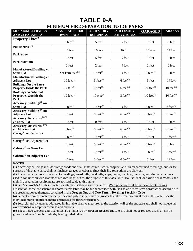
138
TABLE 9-AMINIMUM FIRE SEPARATION INSIDE PARKS
MINIMUM SETBACKSAND CLEARANCES
MANUFACTUREDDWELLINGS
ACCESSORYBUILDINGS
ACCESSORYSTRUCTURES
GARAGES CABANAS
Property Line(4)
5 feet(6) 5 feet 5 feet 5 feet 5 feet
Public Street(4)
10 feet 10 feet 10 feet 10 feet 10 feetPark Street
5 feet 5 feet 5 feet 5 feet 5 feetPark Sidewalk
2 feet 2 feet 0 feet 2 feet 2 feetManufactured Dwelling onSame Lot Not Permitted(6) 3 feet(3) 0 feet 6 feet(3) 0 feetManufactured Dwelling onAdjacent Lot 10 feet(7) 6 feet(3) 6 feet(3) 6 feet 10 feetBuildings On the SameProperty Inside the Park 10 feet(3) 6 feet(3) 6 feet(3) 10 feet(3) 10 feet(3)
Buildings on AdjacentProperties Outside thePark
10 feet(3) 10 feet(3) 3 feet(3) 10 feet(3) 10 feet(3)
Accessory Buildings(1) onSame Lot 3 feet(3) 3 feet(3) 0 feet 3 feet(3) 3 feet(3)
Accessory Buildings(1) onAdjacent Lot 6 feet 6 feet(3) 6 feet(3) 6 feet(3) 6 feet(3)
Accessory Structures(2),(5)
on Same Lot 0 feet 0 feet 0 feet 0 feet 0 feetAccessory Structures(2),(5)
on Adjacent Lot 6 feet(3) 6 feet(3) 6 feet(3) 6 feet(3) 6 feet(3)
Garage(1) on Same Lot6 feet(3) 3 feet(3) 0 feet 0 feet 6 feet(3)
Garage(1) on Adjacent Lot6 feet 6 feet(3) 6 feet(3) 6 feet(3) 6 feet
Cabana(1) on Same Lot0 feet 3 feet(3) 0 feet 6 feet(3) 6 feet(3)
Cabana(1) on Adjacent Lot10 feet 6 feet(3) 6 feet(3) 6 feet 10 feet
NOTES:(1) Accessory buildings include storage sheds and similar structures used in conjunction with manufactured dwellings, but for thepurpose of this table only, shall not include garages or cabanas since their fire separations are different.(2) Accessory structures include decks, landings, guard rails, hand rails, steps, ramps, awnings, carports, and similar structuresused in conjunction with manufactured dwellings, but for the purpose of this table only, shall not include skirting or ramadas sincetheir fire separation requirements are not applicable to this table.(3) See Section 9-5.3 of this Chapter for alternate setbacks and clearances. With prior approval from the authority havingjurisdiction, those fire separations noted in this table may be further reduced with the use of fire resistive construction according tothe prescriptive requirements contained in the Oregon One and Two Family Dwelling Specialty Code.(4) Setbacks from perimeter property lines and public streets may be greater than those dimensions shown in this table. See theindividual municipalities planning ordinances for further restrictions.(5) Setbacks and clearances addressed in this table shall be measured to the exterior wall of the structure and shall not include theeave overhangs except for awnings and carports.(6) These noted setbacks and clearances are established by Oregon Revised Statute and shall not be reduced and shall not begiven a variance from the authority having jurisdiction.
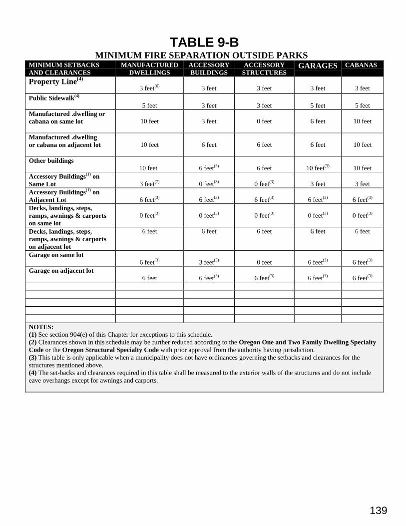
139
TABLE 9-BMINIMUM FIRE SEPARATION OUTSIDE PARKS
MINIMUM SETBACKSAND CLEARANCES
MANUFACTUREDDWELLINGS
ACCESSORYBUILDINGS
ACCESSORYSTRUCTURES
GARAGES CABANAS
Property Line(4)
3 feet(6) 3 feet 3 feet 3 feet 3 feet
Public Sidewalk(4)
5 feet 3 feet 3 feet 5 feet 5 feetManufactured .dwelling orcabana on same lot 10 feet 3 feet 0 feet 6 feet 10 feet
Manufactured .dwellingor cabana on adjacent lot 10 feet 6 feet 6 feet 6 feet 10 feet
Other buildings 10 feet 6 feet(3) 6 feet 10 feet(3) 10 feet
Accessory Buildings(1) onSame Lot 3 feet(7) 0 feet(3) 0 feet(3) 3 feet 3 feetAccessory Buildings(1) onAdjacent Lot 6 feet(3) 6 feet(3) 6 feet(3) 6 feet(3) 6 feet(3)
Decks, landings, steps,ramps, awnings & carportson same lot
0 feet(3) 0 feet(3) 0 feet(3) 0 feet(3) 0 feet(3)
Decks, landings, steps,ramps, awnings & carportson adjacent lot
6 feet 6 feet 6 feet 6 feet 6 feet
Garage on same lot6 feet(3) 3 feet(3) 0 feet 6 feet(3) 6 feet(3)
Garage on adjacent lot6 feet 6 feet(3) 6 feet(3) 6 feet(3) 6 feet(3)
NOTES:(1) See section 904(e) of this Chapter for exceptions to this schedule.(2) Clearances shown in this schedule may be further reduced according to the Oregon One and Two Family Dwelling SpecialtyCode or the Oregon Structural Specialty Code with prior approval from the authority having jurisdiction.(3) This table is only applicable when a municipality does not have ordinances governing the setbacks and clearances for thestructures mentioned above.(4) The set-backs and clearances required in this table shall be measured to the exterior walls of the structures and do not includeeave overhangs except for awnings and carports.
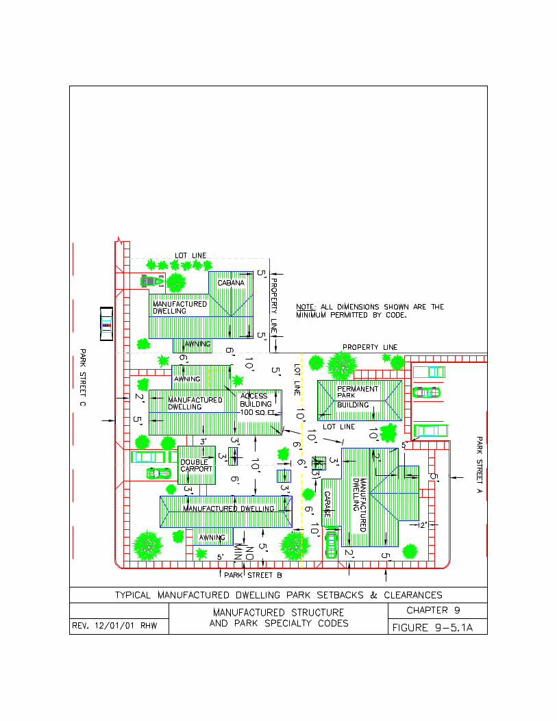
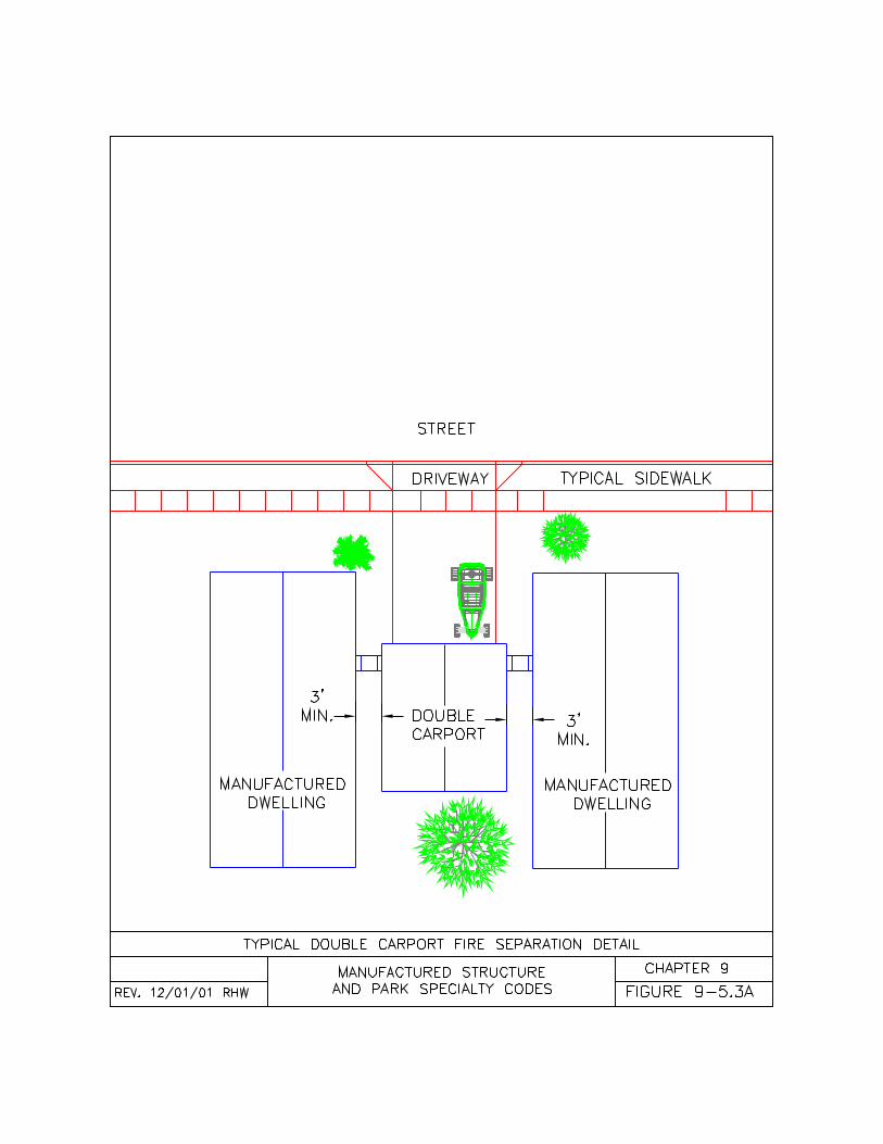
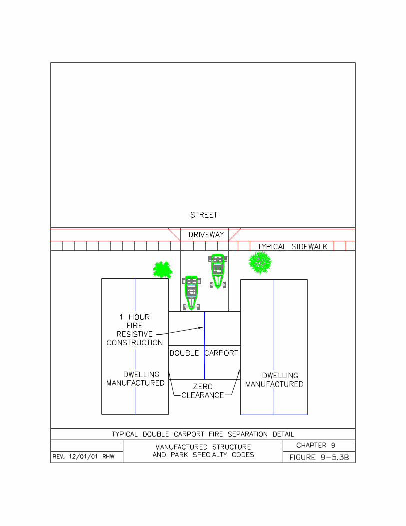
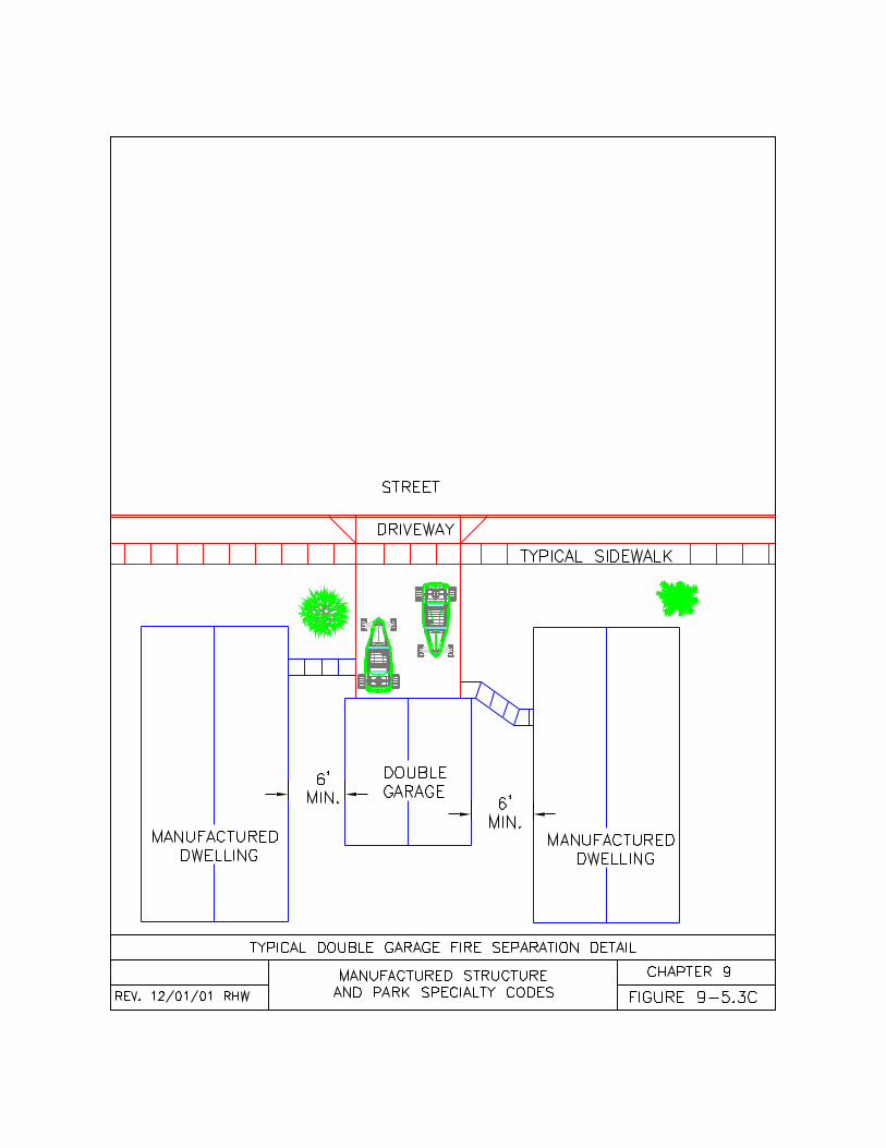
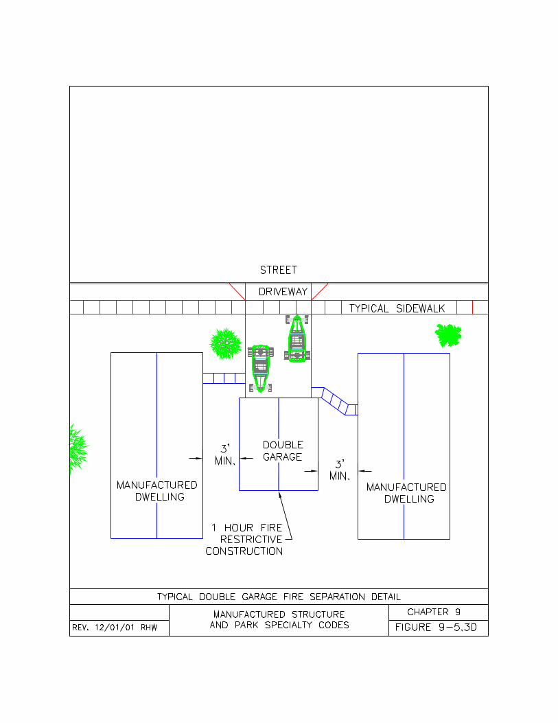
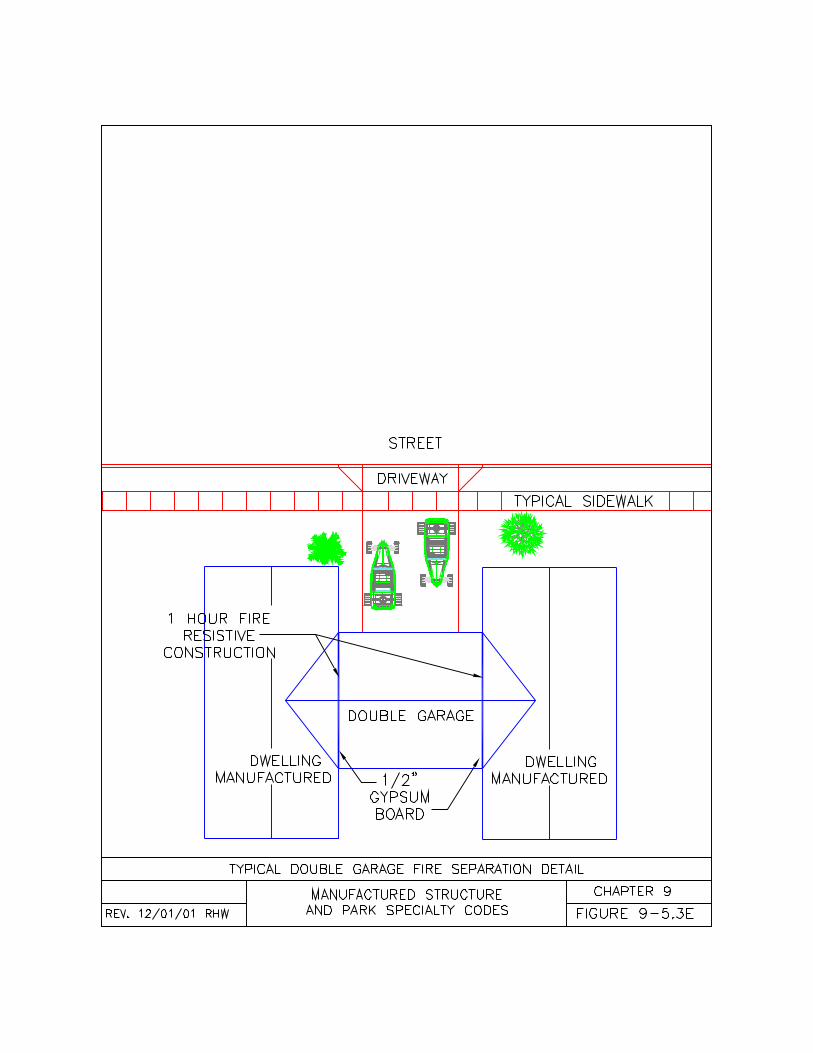
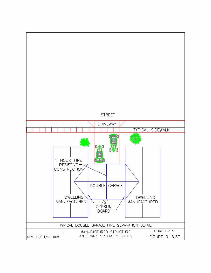
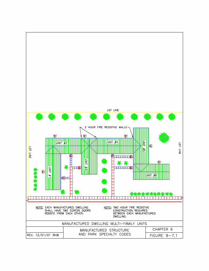
E
E
E
E
E E E
E
E
E
E
E
141
CHAPTER TENMANUFACTURED DWELLING PARKCONSTRUCTION
10-1 General10-2 Land Use and Park Location10-3 Public Safety10-4 Utilities and Storm Water
Drainage10-5 Vehicle and Pedestrian Access10-6 Park Structures10-7 Play Areas10-8 Temporary Parks10-9 Park Additions, Alterations and
Conversions10-10 Maintenance and Safety
10-1 General.10-1.1 Statewide Code. This codeestablishes the minimum and maximumrequirements for the design andconstruction of manufactured dwellingparks throughout the state of Oregon toprovide uniformity and affordability and tokeep construction costs predictable.Except where specifically permitted bythis code, no jurisdiction may require aperson to exceed the requirements of thiscode.
NOTE: See Chapter One for informationon plans, permits, and inspections.
10-1.2 Applicability of Code. Thischapter of the code is applicable to allmobile home parks and manufactureddwelling parks except where specificallyexempted by one of the following:(a) Except where specifically excluded inORS 446.055, four or more manufactureddwellings located on a single parcel ofland constitutes a mobile home ormanufactured dwelling park and shall besubject to this code;(b) Except where specifically excluded inORS 446.090 and 446.105, mobile homeand manufactured dwelling parks shallcomply with all applicable provisions ofthis code; and(c) Parks existing at the time of theeffective date of this code may continue
their use providing their use was legal atthe time this code was adopted.
10-1.3 Permitted Park Use. Parks mayonly be used according to the followingrequirements:(a) Manufactured dwelling parks areintended for the siting of manufactureddwellings only to serve as single familydwellings on a temporary or full timebasis;(b) Site built single or multi familydwellings existing before the constructionof the park may remain in the park;(c) Only one new site built single familydwelling shall be constructed in a park foruse by the park owner, manager, orcaretaker;(d) Recreational vehicles (including parktrailers) and recreational structures arenot permitted in mobile home ormanufactured dwelling parks exceptunder the following conditions:1. Park trailer recreational vehicles (RV)may be permitted within a manufactureddwelling park if the park trailer RV islabeled as both a recreational vehicle anda manufactured home and bears both aHUD Label and a state recreationalvehicle insignia of compliance. Parktrailer RV’s labeled as recreationalvehicles only are not permitted inmanufactured dwelling parks;2. Recreational vehicles are permitted inmobile home parks built prior to August 5,1959;3. Recreational vehicles are permitted tobe stored in a mobile home ormanufactured dwelling park in an areadesignated by the park owner or operatorfor such storage; and4. Recreational vehicles are permitted inthe recreation park area of a combinationpark.(e) Combination recreational vehicleparks and mobile home or manufactureddwelling parks, known as “combinationparks”, may be constructed on the sameproperty under the following conditions:1. Combination parks shall be zoned forboth uses;
142
2. Combination parks shall have priorapproval from the authority havingjurisdiction and the local planningdepartment;3. Combination parks shall havedesignated areas for recreational vehiclesand for manufactured dwellings;4. Where there are common amenitiesserving both parks (such as streets orplay areas), the park shall meet the mostrestrictive requirements of both parkcodes; and5. Existing mobile home, manufactureddwelling, or recreation parks may beconverted to combination parks if the parkcan meet the conditions listed above.
10-1.4 Park Approval. No person shallconstruct, alter, convert, or expand amobile home or manufactured dwellingpark without first making application tothe authority having jurisdiction,submitting plans, and obtaining permitsaccording to Chapter One of this code.(a) A certificate of occupancy shall beissued when the park is completed andapproved by the authority havingjurisdiction. When a park is built inphases, there shall be a new certificate ofoccupancy issued when each new phaseis completed and approved by theauthority having jurisdiction.(b) The authority having jurisdiction maypermit manufactured dwellings to be sitedand installed in a manufactured dwellingpark prior to issuing a certificate ofoccupancy, however, no manufactureddwelling shall be placed in amanufactured dwelling park without priorapproval from the authority havingjurisdiction.
10-1.5 Unusual Construction. Thiscode is not intended to limit theappropriate use of materials, equipment,or methods of design or construction notspecifically prescribed by this code. Aperson may design for unusualconstruction using alternate materials ormethods not provided for in this code aslong as the alternate method or materialis at least equivalent to the requirements
of this code in suitability, quality, strength,effectiveness, fire resistance, durability,dimensional stability, safety, andsanitation. All alternate methods ormaterials shall have prior approval fromthe authority having jurisdiction.
10-2 Land Use Compatibility and ParkLocation.10-2.1 Land Use. No manufactureddwelling park or mobile home park shallbe constructed, altered, converted, orexpanded unless it is in accordance withcomprehensive plan and local zoningordinance and meets the requirements ofthis code.(a) The local planning department isgiven specific authority to establishreasonable criteria related to the followingas long as the criteria for a park is notless than the minimum requirements inthis code and not greater than therequirements for single family uses in theunderlying zone:1. The location of the park within themunicipality;2. The density of the park;3. The minimum setbacks around theperimeter of the park;4. The minimum setbacks and bufferzones around existing wetlands within thepark;5. The minimum setbacks and bufferzones around a stream, creek, or riverrunning through the park;6. The landscaping, fencing, and bufferzones around the perimeter of the park;7. The establishment of open areas andgreen ways within the park;8. The orientation of those manufactureddwellings and accessory buildings andstructures within the park adjacent to apublic way;9. The location of play areas within thepark;10. The size and construction of the parkstreet, curbs, and sidewalks where theyconnect to the public way for the first 100feet (30.5 m) of length or to the firstintersecting street within the park,whichever is less;
143
11. The location, size, and construction ofa public street(s) running through the parkwhen the municipality can demonstratethe street(s) is needed as required forconductivity or when the street(s) isalready designated in the municipalitiesacknowledged transportation systemplan. All other streets within the park shallremain private and a part of the parkproperty;12. The street and address designationswithin the park;13. The color and style of street signagewithin the park; and14. The control of erosion andconstruction debris.(b) The local planning department mayprohibit the disturbance of certain aspectsof the land having a redeeming value,such as land with mature trees,geological formations, waterways, orhistorical significance.(c) A municipality is not permitted toestablish or require constructionstandards for manufactured dwellingparks or manufactured dwellinginstallations that are more or lessrestrictive than this code except wherespecifically permitted in this code.
10-2.2 Hazardous Locations.Manufactured dwelling parks shall belocated according to the following:(a) Manufactured dwelling parks shall notbe located in a floodway. Existing mobilehome or manufactured dwelling parkslocated in floodways shall not bepermitted to expand within the floodway.(b) Manufactured dwelling parks or parkexpansions shall not be located in a floodrelated erosion area without specificapproval from the authority havingjurisdiction.(c) Manufactured dwelling parks or parkexpansions shall not be located in ageological hazard area (includes areaswith landslide potential or otherhazardous conditions) without specificapproval from the authority havingjurisdiction.(d) Manufactured dwelling parks or parkexpansions shall not be permitted in a
flood hazard area unless the stands areelevated above the Base FloodElevation (BFE) as identified on theFlood Insurance Rate Map (FIRM).(e) Manufactured dwelling parks or parkexpansions shall not be permitted in aCoastal High Hazard Zone, as identifiedon the FIRM, unless the affected park,park buildings, manufactured dwellings,accessory buildings, and accessorystructures within the zone meet therequirements of Section 3108 of theOregon Structural Specialty Code(OSSC).
NOTE: The information in subsection 10-2.2 is based on the Federal EmergencyManagement Agency (FEMA) regulation44 CFR, Chapter 1 published October 1,1990.
10-2.3 Suitability of Site. The site shallbe suitable for its intended use to theauthority having jurisdiction based on thiscode and local land use regulationsaccording to the following:(a) Manufactured dwelling parks or parkexpansions shall not be located on landthat is unsuitable due to swampy terrain,lack of drainage, or proximity to thebreeding places of rodents or verminunless improvements have been made tothe land to eliminate or control thehazards and such improvements areacceptable to the authority havingjurisdiction;(b) The authority having jurisdiction shallconsider the condition of the soil, groundwater level, drainage, and topography ofthe land prior to issuing constructionpermits for a manufactured dwelling parkor the expansion of a mobile home park;(c) The authority having jurisdiction shallconsider the hazards of flood relatederosion areas, coastal high hazard zones,slide hazard areas, and other unstableconditions prior to issuing constructionpermits for a manufactured dwelling parkor the expansion of a mobile home park.(d) Each manufactured dwelling standshall have or be improved to have a
144
minimum capacity of 1,000 pounds persquare foot (14,788 kg/m(2));(e) The ground supporting park streets,alleys, driveways, and commondriveways shall have or be improved tohave a minimum soil bearing capacity of2,000 pounds per square foot (29,576kg/m(2));(f) Each manufactured dwelling lot withina park shall be prepared according tochapter 3 prior to the installation of anymanufactured dwelling;(g) Fills over 12 inches (30 cm) in depthshall be placed in accordance withaccepted engineering practice. A soilinvestigation report of satisfactoryplacement of fill, acceptable to theauthority having jurisdiction, shall besubmitted prior to final approval of thepark;(h) Cuts and fills in flood hazard areasshall be equal in area so that the fillmaterial does not cause a rise in thewater level; and(i) The slope of cut or fill surfaces shall beno steeper than is safe for the intendeduse and shall be no steeper than 1 unitvertical in 2 units horizontal or 50 percentunless the permittee furnishes a soilsengineering or engineering geologyreport, or both, stating that the site hasbeen investigated, and given an opinionthat a cut at a steeper slope will be stableand not create a hazard to public orprivate property.
10-3 Public Safety.10-3.1 Park Design. Manufactureddwelling parks shall be designed toprovide reasonable safeguards againstfire and other hazards according to thefollowing:(a) Manufactured dwellings, parkbuildings, accessory buildings, andaccessory structures shall be arranged ina manner that does not prevent or restrictaccess by emergency equipment andpersonnel;(b) Streets, alleys, common driveways,park buildings, and manufactureddwelling lots shall be identified accordingto the street naming and numbering
policies of the authority havingjurisdiction;(c) Fire apparatus shall be able toapproach within 50 feet (15.2 m) of eachmanufactured dwelling or park buildingwithin a manufactured dwelling park; and(d) Manufactured dwellings, parkbuildings, accessory buildings, andaccessory structures shall be located in amanner that provides the minimumsetbacks and clearances required inChapter 9 of this code.
10-3.2 Water Supplies. Water suppliesfor fire department operations shall be asrequired by the local fire official.
10-3.3 Identification. Manufactureddwellings and park buildings shall beposted in a conspicuous and uniformmanner that is clearly visible from thestreet or alley serving the site accordingto the following:(a) Each park shall have a generaldirectory located at each entrance to thepark. The directory shall indicate streetnames, addresses and/or lot numbersand be easily legible from a vehicleentering the park;(b) Each park street, alley or commondriveway shall be posted with a signidentifying its name according to therequirements of the authority havingjurisdiction;(c) Each manufactured dwelling lot shallbe clearly identified with 3 inch (76 mm)high numbers on the curb, mail box,home, or other location acceptable to theauthority having jurisdiction;(d) Each park building shall be clearlyidentified with 3 inch (76 mm) highcharacters giving the name or number;(e) The park shall be identified by nameand street address on the public wayaccording the local municipality’srequirements;(f) Curbs or streets shall be painted with a4 inch (10 cm) wide red stripe 10 feet(305 cm) either side of a fire hydrant;(g) Applicable park streets, alleys, orcommon driveways serving as fire lanesshall be marked with red painted curbs,
145
striped pavement, or 12 inch by 18 inch(30 cm by 46 cm) white signs with redletters, to indicate where parking isprohibited. The marking shall state “FireLane - No Parking” and shall be inminimum 3 inch (76 mm) high blockletters and posted every 25 feet;(h) One way park streets shall be postedwith a 18 inch by 24 inch (46 cm by 61cm) white sign with black letters indicating“ONE WAY” with an arrow to indicate thecorrect direction of the traffic flow;(i) Park streets shall be posted with a 24inch by 24 inch (61 cm by 61 cm) redoctagon shaped sign with white lettersindicating “STOP” located at eachintersection with the park and at the exitfrom the park onto the public way whenrequired by the municipality. A stop signis not necessary at the exit from the parkwhen it exits into an intersectioncontrolled by municipal traffic signallighting;(j) The approach to vehicle bridges withinthe park shall be posted at each end withan 18 inch by 18 inch (46 cm by 46 cm)white sign with black letters indicating“___ TON LIMIT” showing the maximumcapacity of the bridge according to theapproved engineering;(k) Parking for disabled persons shall bemarked and posted according to Chapter11 of the OSSC;(l) Signs required by this chapter shall belocated not less than 80 inches (203 cm)from the center of the sign to the groundand shall be made of durable materialacceptable to the authority havingjurisdiction. Sign posts shall be made ofhot rolled steel, 3-1/2 inch by 3-1/2 inch(89 mm by 89 mm) pressure treatedwood, or fiberglass manufactured forsuch applications.
10-3.4 Lighting. Manufactured dwellingpark streets, alleys, sidewalks, walkways,shall be illuminated to provide for thesafety of all park residents and guestsaccording to the following:(a) Park luminaires (lighting fixtures) shallbe located to provide the following levelsof illumination:
1. Park streets, alleys, and abuttingsidewalks or walkways shall haveluminaires that provide an average of 4.0lux maintained over the entire surface,with average to minimum uniformity rationot to exceed 6 to 1;2. Park sidewalks or walkways notabutting a street shall have luminairesthat provide an average of 4.0 luxmaintained over the entire surface, withaverage to minimum uniformity ratio notto exceed 6 to 1;3. The park street connecting to thepublic way shall have luminaires thatprovide an average of 6.0 lux maintainedover the entire surface, with average tominimum uniformity ratio not to exceed 4to 1.(b) Park luminaires shall be controlled byphotocells set to turn on automatically atdusk and off at dawn;(c) Park luminaires shall not be controlledby individual park residents;(d) Park luminaires may be controlled formaintenance purposes only by the parkowner or operator or by a contractingutility company;
10-3.5 Density. The total area of a lotoccupied by a manufactured dwelling andall accessory structures and buildingsshall not exceed 75 percent of the total lotarea when located in a manufactureddwelling park, mobile home park, orcombination park.
10-4 Utilities and Storm WaterDrainage.10-4.1 Utility Services. Themanufactured dwelling park owner shallprovide the following to eachmanufactured dwelling lot as required:(a) An adequate supply of potable water(not less than 20 psi (138 kPa) at thesupply connection) shall be provided toeach manufactured dwelling lot in amobile home or manufactured dwellingpark;1. All plumbing installations in connectionwith mobile home or manufactureddwelling park construction, alteration,repair, conversion, or addition shall be
146
made according to this code and, wherenot specific, to the Oregon PlumbingSpecialty Code;2. Piping shall be accessible and can onlybe placed under the manufactureddwelling it is serving. Piping cannot belaid beneath a manufactured dwelling forthe purpose of providing service to anadjacent manufactured dwelling or otherstructure on an adjacent lot; and3. When a park is located in a floodhazard area, all plumbing openings shallbe located a minimum of 12 inches (30cm) above the base flood elevation or beequipped with approved backwatervalves.(b) Sewage disposal facilities shall bemade available on each manufactureddwelling lot within a park to adequatelydispose of all sewage. The sewagesystem within a park shall be installedand connected according to Chapter 5and where not specific, to the OregonPlumbing Specialty Code and theDepartment of Environmental Quality(DEQ) rules, OAR 340-71;(c) An adequate amount of electric powershall be supplied to each manufactureddwelling lot and shall be equivalent to theamperage required for the manufactureddwelling.(d) Where natural gas is provided, anadequate supply of natural gas shall besupplied to each manufactured dwellingusing the product. Gas piping within thepark shall be installed and connectedaccording to Chapter 6 and where notspecific, to the Oregon MechanicalSpecialty Code and NFPA 54; and(e) Where liquid petroleum gas (LPG) isprovided, an adequate supply of LPGshall be supplied to each manufactureddwelling using the product. The LPG tankand piping shall be installed andconnected according to Chapter 6 andwhere not specific, to the requirements ofthe State Fire Marshal and NFPA 58.(f) The parks water, sewer, gas, electric,or storm water drainage lines shall not belocated under a manufactured dwelling,accessory building, or accessorystructure or located in an area where a
manufactured dwelling, accessorybuilding, or accessory structure is likely tobe placed. Individual water, sewer, andgas branch lines may terminate under themanufactured dwelling they serve.
10-4.2 Manufactured Dwelling ParkElectrical Installations. All electricalinstallations in connection with parkconstruction, alteration, repair,conversion, or addition shall be madeaccording to this code and, where notspecific, to the NEC.(a) Each lot in a mobile home ormanufactured dwelling park shall besupplied with electrical service of not lessthan 100 Amps and shall contain ameans for connecting an accessorybuilding or additional electricalequipment.(b) When a manufactured dwelling park islocated in a flood hazard area, allelectrical connections in the park shall bea minimum of 12 inches (30 cm) abovethe base flood level.(c) Newer manufactured dwellingsinstalled in older parks that exceed thecapacity of the existing park serviceequipment shall not be energized until thepark’s service equipment has beenupgraded.
10-4.3 Storm Water Drainage. Allmanufactured dwelling lots, streets, andalleys shall be provided with adequatestorm drainage according to the following:(a) Storm water drainage systems shallbe designed and sized by an Oregonprofessional engineer to thespecifications provided by the authorityhaving jurisdiction and The Departmentof Environmental Quality (DEQ);(b) When deemed necessary by theauthority having jurisdiction, storm waterdrainage shall include suitable detention;(c) Storm water shall not be directed intoa sanitary sewer system. Combinedsanitary sewers and storm drains areprohibited;(d) Each manufactured dwelling lot shallbe provided with at least one 4 inch (101mm) or two 3 inch (76 mm) storm water
147
drain(s) to the street. Where curbs areused, the curbs shall be built withequivalently sized weepholes. If the slopeof the land prevents lot surface and raindrain storm water from draining to thestreet, a storm water lateral shall beprovided from the site to the park’s stormwater system;(e) Dry wells or infiltrator systems shallonly be used for storm water drains whensoil tests have been performed by aqualified Oregon geological engineer orgeotechnical engineer showing that soilsare suitable for the subsurface disposal ofstorm water. Test results shall besubmitted to the authority havingjurisdiction for review and approval priorto constructing the system; and(f) When a park is being built in phases,the park’s storm water drainage plan shalltake into consideration present and futurewater volumes based on 10 year stormdata.
10-4.4 Fuel Gas Pipe Installations. Allfuel gas piping systems serving amanufactured dwelling shall beconstructed according to the minimumrequirements of this code and, where notspecific, to the Oregon MechanicalSpecialty Code (Section 1312), theNational Fuel Gas Code (NFPA 54–1999), and the Liquefied Petroleum GasCode (NFPA 58-1998). Gas supplysystems, where provided on amanufactured dwelling lot from anunderground gas supply piping system,shall be located and arranged to permitattachment to the manufactured dwellingaccording to this chapter.(a) The gas supply to a manufactureddwelling shall be located within 2 feet (66mm) of the manufactured dwelling stand.(b) Privately owned or installed fuel gassupply lines in a manufactured dwellingpark shall be sized and installedaccording to Chapter 13 of the OregonMechanical Specialty Code. Liquidpetroleum gas storage tanks and supplypiping systems in manufactured dwellingparks shall be installed according to therequirements of the 1998 Oregon
Uniform Fire Code. There shall be areadily accessible and identified shutoffvalve controlling the flow of gas to theentire gas-piping system installed nearthe point of connection to the utilityservice supply connection or to the mainliquefied petroleum gas storage tank.(c) A privately owned or installed gassupply to a manufactured dwelling,including the riser, regulator, meter,valves, and other exposed equipmentshall be located where they are protectedagainst accidental damage. All buriedpark owned or installed metallic gaspiping shall be protected from corrosionby approved coatings or wrappingmaterials to a point at least 6 inches (152mm) above ground. Where metallic gaspiping has or is required to have cathodicprotection, it shall be installed to conformto the provisions of 49 CFR 192.(d) Privately owned gas meters, whereprovided on a manufactured dwelling lot,shall be installed according to thefollowing:(1) Gas meters shall be adequatelysupported by an anodeless riser supportstake to a depth adequate to bolster orsupport the meter set weight requirementor by other means acceptable to theauthority having jurisdiction;2. Gas meters shall not depend on thegas outlet riser for support, and shall notbe supported by the manufactureddwelling;3. Each gas meter shall be installed in anaccessible location and shall be providedwith unions or other fittings to permitservicing or replacement of the meter ormeter parts;4. Meters shall not be installed inunventilated or inaccessible locations orcloser than 3 feet (91 cm) to sources ofignition;5. All gas meter installations shall beprovided with shutoff valves or cockslocated adjacent to and on the inlet sideof the meters. In the case of a singlemeter installation utilizing an LPGcontainer, the container service valveshall be permitted to be used in lieu of themanufactured dwelling shutoff valve; and
148
6. All gas meter installations shall beprovided with test tees located adjacentto and on the outlet side of the meters.
10-4.5 Underground Gas Piping.Privately owned underground gas piping,when provided, shall be installedaccording to the following:(a) All gas piping installed below groundlevel shall have a minimum earthcovering of 18 inches (45 cm) and shallbe installed with at least 12 inches 9305mm) clearance in any direction from anyother underground utility system;(b) Underground gas piping shall not beplaced in contact with other metallicobjects such as pipes or wires;(c) Underground nonmetalic gas linesshall have a number 18 AWG yellowinsulated copper tracer wire conductorinstalled adjacent to the gas line and shallbe accessible or terminate above groundat each end;(d) Underground gas piping shall not beinstalled beneath a manufactureddwelling, accessory building, oraccessory structure unless installedaccording to the following conditions:1. Underground gas piping located undera manufactured dwelling, accessorybuilding, or accessory structure shall beencased in a conduit capable ofwithstanding superimposed loads;2. The conduit shall extend to a point notless than 4 inches (102 mm) beyond theoutside wall of the manufactured dwelling,accessory building, or accessorystructure, and be vented above grade tothe outside; and3. Where the conduit terminates within amanufactured dwelling, accessorybuilding, or accessory structure, it shallbe readily accessible and the spacebetween the conduit and the gas pipingshall be sealed to prevent leakage of gasinto the manufactured dwelling,accessory building, or accessorystructure.
10-5 Vehicle and Pedestrian Access.10-5.1.1 Streets and Alley Design. Eacharea of a manufactured dwelling park
shall be accessible from the public waythrough a system of streets, alleys, andcommon driveways designed accordingto the following:(a) Park streets and alleys shall be sizedaccording to Table 10-C (see Figure 10-5.1A) and (see Figure 10-5.1B);(b) Park streets may have center dividerswith one way traffic on each side. Eachlane on either side of a center dividershall be sized according to Table 10-C ofthis code. Center dividers shall bedesigned according to the followingcriteria (see Figure 10-5.1C):1. Center dividers shall always be locatedon the left side (driver’s side) of thevehicles;2. Center dividers shall have a minimum60 foot (18.3 m) long break located amaximum of every 200 feet (61 m) ofstreet length;3. Center dividers may be paved orlandscaped;4. Center dividers may be occupied bybus shelters, gazebos, pump houses, orguardhouses not exceeding 120 squarefeet (1114.8 m(2)) each in floor area.5. Center dividers may contain an openstorm drain or water detention facilitieswhere permitted by the authority havingjurisdiction;6. Center dividers may contain therequired play area if adequately protectedfrom the traffic area;7. Center dividers may contain off streetparking;8. Center dividers shall not exceed 50feet (15.2 m) in width between the twolanes of the street; and9. Center dividers shall not containmanufactured dwellings, accessorybuildings, accessory structures, or otherpark buildings except for those mentionedin this section.(c) Park streets connecting to the publicway shall be sized according to Table 10-C and shall extend undiminished in sizefrom the public way 100 feet (30.5 m) orto the first cross street within the park,which ever is less. (see Figure 10-5.1D);(d) Alleys shall be sized according toTable 10-C.
149
(e) Park streets and alleys shall beappropriately marked indicating whereon-street parking is prohibited;(f) All park streets, alleys, driveways,sidewalks, and walkways shall remain theproperty of the park except when:1. The street is a public street runningthrough the park when permitted bySection 10-2.1(a)(12) of this chapter;2. The street is a public street inexistence prior to the construction of thepark.(g) Streets and alleys shall be limited inlength according to the following:1. Streets with both an inlet and outlet atopposite ends are not restricted to amaximum length (see Figure 10-5.1C);2. Alleys with both an inlet and outlet arerestricted to a maximum length of 400feet (121.9 m);3. Streets or alleys with dead ends shallbe limited to a maximum of 150 feet (45.7m) in length when there is no approvedturnaround provided (see Figures 10-5.1A, B, and C);4. Streets or alleys with approvedturnarounds shall be limited in length to amaximum of 300 feet (91.4 m) excludingthe turnaround (see Figures 10-5.1A andC); and5. Streets or alleys with dead ends maybranch off any street or approvedturnaround (see Figures 10-5.1A and C).(h) Curved park streets and alleys shallhave a minimum 29 foot (8.8 m) radius onthe inside edge and a minimum 55 foot(16.7 m) radius on the outside edge (seeFigure 10-5.1C);(i) Park street or alley intersections shallhave a minimum inside radius of 15 feet(4.6 m) (see Figure 10-5.1C);(j) Park streets or alleys providing accessto the public way shall have a minimuminside radius of 35 feet (10.6 m);(k) Park street or alley intersections shallhave a minimum angle of 70 degrees(see Figure 10-5.1C);(l) Park streets and alleys shall have aminimum vertical clearance of 16 feet (4.9m);(m) Dead-end streets or alleys in excessof 150 feet (45.7 m) in length shall have
approved turnarounds. Turnarounds shallhave a wearing surface equivalent to thatof the streets being served by theturnaround. Turnarounds shall beconstructed according to the following:1. Cul-de-sacs with parallel parkingpermitted shall have a minimum 38-foot(11.5 m) radius excluding curbs,sidewalks, walkways, or shoulders. Cul-de-sacs with parking prohibited shall havea minimum 30-foot (9.1 m) radiusexcluding any curbs, sidewalks,walkways, or shoulders and shall beappropriately marked to indicate parkingis prohibited. Street connections to cul-de-sacs shall have a minimum insideradius of 20 feet (6.1 m) (see Figure 10-5.1A); or2. Hammerhead turnarounds shall be aminimum of 20 feet (6.1 m) wideexcluding any curbs, sidewalks,walkways, or shoulders, shall have aminimum back up length of 30 feet (9.1m), and shall be appropriately marked toindicate parking is prohibited. Streetconnections to hammerhead turnaroundsshall have a minimum inside radius of 20feet (6.1 m) (see Figure 10-5.1B).(n) Streets and alleys shall not havefences, walls, hedges, or otherobstructions at corners or intersectionsblocking the driver’s view of oncomingpedestrian or vehicle traffic. Fences orwalls within 10 feet (3 m) of a street oralley corner or intersection shall be amaximum of 4 feet (122 cm) high with 75percent of the area in the upper 2 feet (61cm) open to permit vision through thefence or wall.
10-5.1.2 Street and Alley Construction.Manufactured dwelling park streets andalleys shall be designed and constructedaccording to the following:(a) Park streets and alleys shall not havea running grade exceeding 12 percent;(b) Park streets and alleys shall have aminimum grade of 1 percent running thelength of the streets;(c) Park streets and alleys with curbsshall have a crown with a minimum 2percent cross slope (see Figure 10-5.1E)
150
or an inverted crown with a minimum 1percent cross slope (see Figure 10-5.1G), or a flat sheet street with aminimum single slope of 2%;(d) Park streets and alleys without curbsshall have a crown with a minimum .5percent cross slope (see Figure 10-5.1F)or an inverted crown with a minimum 1percent grade (see Figure 10-5.1G), or aflat sheet street with a minimum singleslope of 1%;(e) Park streets and alleys without curbsshall have a 2 foot (61 cm) shoulder oneach side (see Figures 10-5.1F, G, andH);(f) Park streets with center dividers butwithout curbs shall have an invertedcrown with a minimum 1 percent grade(see Figure 10-5.1H);(g) Park streets with center dividers andcurbs shall have each lane slope awayfrom the center divider with a minimum 1percent grade or shall have a crown oneach lane with a minimum 2 percentgrade to each side (see Figure 10-5.1I);(h) Park streets shall be designed andconstructed to prevent the accumulationof water and provide adequate drainageaccording to the following:(i) Crowned streets with curbs shall beprovided with inlets for proper drainage ofsurface water (see Figure 10-5.1J); and(j) Inverted crowned streets shall haveand drainage basins and gutters locateddown the center of the street (seeFigures 10-5.1K and 10-5.1L);(k) Park streets and alleys shall beengineered and designed for minimum of5,000(18-kip) single axle loads and shall besurfaced according to the following:1. With a 2 inch (5 cm) wearing course ofasphaltic-concrete over a 6 inch (15 cm)well-compacted and well-graded baseconsisting of 4 inches (10 cm) of 1-1/2inch (38 mm) minus crushed rock toppedwith 2 inches (5 cm) of ¾ inch (19 mm)minus crushed rock (see Figures 10-5.1E through I);2. With a 4 inch (10 cm) wearing courseof Portland cement concrete over a 6 inch(15 cm) well-compacted and well-graded
base consisting of 4 inches (10 cm) of 1-1/2 inch (38 mm) minus crushed rocktopped with two inches of ¾-inch (19 mm)minus crushed rock (see Figures 10-5.1E through I). Concrete shall have gridwork of expansion/contraction jointsplaced in each direction at 10 feet (3.5 m)apart. Concrete shall have acompressive strength not less than 2,500pounds (1,135 kg) per 1 square inch(6.45 square centimeters) in 28 days with7 days of cure time; or3. Parks located East of the Cascadesummit may have streets with a wearingsurface of well-graded crushed rock orclean well-graded quarry or pit-runmaterial over a well-compacted base of 4inches (10 cm) of ¾ inch (19 mm) minusor 1-1/2 inch (38 mm) minus crushedrock, where permitted by the localplanning department.4. All base materials shall be clean andfree from organic materials;5. All surfaces and materials on which thebase is to be constructed shall bethoroughly compacted before thepavement surface is placed;6. Lime treatment of native soils with a pHgreater than 10 may be substituted forbase rock with an application of not lessthan 25 pounds (11 kg) of slacked limeper square yard mixed thoroughly(rototilled) to a minimum depth of 6inches (15 cm); and7. Cement treatment of native soils with apH less than 10 may be substituted forbase rock with an application of not lessthan 25 pounds (11 kg) of Portlandcement per square yard mixed thoroughly(rototilled) to a minimum depth of 6inches (15 cm).
10-5.2 Driveways. Each manufactureddwelling lot shall have a drivewayconnecting to a park street or alley toallow individuals access to and egressfrom their manufactured dwelling.Driveways shall be designed andconstructed according to the following:(a) Individual driveways to onemanufactured dwelling shall have a
151
minimum 10-foot (3 m) wide wearingsurface (see Figure 10-5.2);(b) Double driveways serving twoadjacent manufactured dwelling shallhave a minimum 24 feet (7.3 m) widewearing surface (see Figure 10-5.2);(c) Driveways shall be constructed onground having, or improved to have, aminimum soil bearing capacity of 1,000pounds per square foot (4.883 kg/m2);(d) Driveways shall be designed andconstructed to prevent the accumulationof water and provide adequate drainage;(e) Driveways shall have a wearingsurface made of asphaltic-concrete,Portland concrete cement, or with otherhard surfaced material approved by theauthority having jurisdiction; and(f) Driveways constructed of concretecement shall have grid work ofexpansion/contraction joints placed ineach direction at 10 feet (3.5 m) apart.(g) Common driveways may serveindividual or double driveways whenmanufactured dwellings are clustered in asingle area such as on flag lots. Commondriveways shall be constructed to thefollowing (see Figure 10-5.2):1. Common driveways may serve up tofour individual manufactured dwellingsbut shall not exceed 100 feet (30.5 m) inlength;2. Common driveways shall have aminimum 20 foot (6.1 m) wideunobstructed right of way for emergencyaccess;3. Common driveways shall have awearing surface constructed equivalent tothat required for the streets or with otherhard surfaced material approved by theauthority having jurisdiction;4. Common driveways shall have aminimum wearing surface area of 12 feet(3.6 m) in width excluding any curbs,sidewalks, walkways, or shoulders withone 4 foot (30 cm) shoulder on each side;5. When parking is permitted, thecommon driveway shall be sizedaccording to Table 10-C of this code;6. Common driveways shall not bepermitted to have parking within theminimum right of way area and shall be
appropriately marked to indicate whereparking is not permitted;7. Common driveways shall have a crownwith a minimum .5 percent grade or aninverted crown with a minimum 1 percentgrade (see Figures 10-5.1F and G);8. Common driveways shall not exceed a12 percent grade;9. Common driveways shall have aminimum 14 foot (4.3 m) radius on theinside corners and a minimum 27 foot(8.3 m) radius on the outside corners; and10. Common driveways shall have aminimum vertical clearance of 16 feet (5m).
10-5.3 Parking. Automobile parking shallbe provided in all mobile home andmanufactured dwelling parks. Parkingareas shall be designed and constructedaccording to the following:(a) Each manufactured dwelling lot shallbe provided with a minimum of twoparking spaces that may be end to end,side to side, or with one on-street parkingspace and one off-street parking space. Ausable garage or carport on amanufactured dwelling lot shall satisfythese parking requirements;(b) One guest parking space shall beprovided for every eight manufactureddwelling lots and shall be located within400 feet (121.9 m) of each manufactureddwelling lot served. A separate guestparking area is not required whereindividual manufactured dwelling lotshave a parking area for three or morevehicles or where streets are sized for on-street parking according to Table 10-C ofthis chapter;(c) Play areas shall have a minimum oftwo parking spaces provided for every2,500 square feet (2470.7 m(2)) of playarea. Parking for a play area shall belocated within 100 feet (30.5 m) of theplay area it serves;(d) Common facilities such as aclubhouse, recreation hall, tennis court,swimming pool, and similar facilities shallhave a minimum of one parking space forevery 30 manufactured dwelling lotswithin the park. If these facilities are open
152
to the public, the parking area shall bebased on the occupant load of thefacilities according to the OregonStructural Specialty Code (OSSC) andthe authority having jurisdiction;(e) The park office shall have one parkingspace for every 50 manufactured dwellinglots within the park except when the parkoffice is located inside a club house,recreation hall, or similar facility whereparking is already provided;(f) Combined parking areas serving morethan one facility or area are permitted butshall not diminish total number of parkingspaces required and shall stay within themaximum distances to each area served;(g) At least 4 percent of the parkingspaces intended for guest parking, officeparking, play areas, recreation areas,club house, community facility, or similarfacilities shall be made accessibleaccording to Chapter 11 of the OSSC;(h) Parking areas, except in designatedfenced and gated storage areas, shallhave a wearing surface equivalent to thatof the park streets, or of other hardsurfaced material approved by theauthority having jurisdiction;(I) Parking areas shall not exceed a 1:20or 5 percent slope;(j) Parking areas shall be designed andconstructed to prevent the accumulationof water and provide adequate drainage(see Figure 10-5.1I and J);(k) When a park is built in phases,parking shall be provided in each phaseand sized appropriately for the numberfacilities and manufactured dwelling lotsin that phase;(l) When a park is built in phases and thecommon facilities are intended to servemore than one phase, the number ofparking spaces at the common facilitiesshall be based on the total number ofmanufactured dwelling lots to be servedin all phases;(m) Street widths shall be increasedbased on the number, type, and locationof the on-street parking according toTable 10-C;
(n) On-street parking spaces, other thanfor parallel parking, shall be marked onthe pavement with a suitable paint;(o) Off-street parking shall be sizedaccording to Table 10-D or as otherwiseapproved by the authority havingjurisdiction; and(p) Areas in parking lots not designed forparking shall be identified as a no parkingarea.
10-5.4 Pedestrian Access. Eachmanufactured dwelling park shall beprovided with an accessible route forpedestrians from each manufactureddwelling lot to each common area orfacility and to the public way. Residentsmay be required to cross the park streetin front of their manufactured dwelling lotto get to a sidewalk or walkway on theother side of the street. This section ofthe code does not require sidewalks orwalkways on individual lots to individualmanufactured dwellings.(a) A sidewalk or walkway shall berequired only on one side of each parkstreet; located through green waysbetween the manufactured dwelling lots;or may be provided in other locationsapproved by the authority havingjurisdiction;(b) Park streets without sidewalks mayhave a designated walkway on one sideof the street. The walkway shall bemarked for pedestrian traffic on thepavement or divided from the traffic andparking area with curbing or similarbarriers (see Figure 10-5.4 and 10-5.4A). Required walkways shall notdiminish the minimum required widths ofstreets or alleys established in Table 10-C of this code;(c) Sidewalks and walkways shall be aminimum of 4 feet (122 cm) in width.(d) Sidewalks and walkways shall providea slip-resistant surface.(e) Sidewalks, curbs, and walkways shallbe accessible according to Chapter 11 ofthe OSSC (see Figures 10-5.4B, C, D, E,F, and H)(f) Sidewalks and walkways shall not bediminished in width by fire hydrants, light
153
poles, signs, curb cuts, or similarobstructions (see Figure 10-5.4G).(g) Sidewalks and walkways shall notexceed a running slope of 1:20 or 5percent and cross slope of 1:50 or 2percent.(h) Alleys and common driveways mayserve as the pedestrian access withoutan increase in size if the slope does notexceed 1:50 or 2 percent (see Figure 10-5.4H).(i) Park streets in temporary parks mayserve as the pedestrian access withoutan increase in size if the slope does notexceed 1:50 or 2 percent.(j) Stairways, ramps, landings, handrails,and guardrails, that are part of thesidewalk or walkway system, shall beconstructed according to the OSSC.(k) When sidewalks are provided in amanufactured dwelling park, they shallmeet the requirements for an accessibleroute and be constructed according toone of the following:1. 3-1/2 inch (9 cm) thick concrete, on anadequate base, with a compressivestrength not less than 2,500 pounds per 1square inch (176 kg/cm(2)) in 28 days with7 days of cure time;2. Asphaltic-concrete or other hardsurfaced material approved by theauthority having jurisdiction;3. Pressure treated foundation gradelumber pressure preservatively treatedaccording to AWPA C22 and identified asin conformance with such standard by anapproved agency; or4. Wood-polymer composite complyingwith ASTM 790, ASTM 2-1037, ASTMD1413, and AWPA EI-72.(l) When walkways are provided in amanufactured dwelling park, they shallmeet the requirements for an accessibleroute and be constructed of hard packed,firm, stable, and slip resistant surface ofrock or other material approved by theauthority having jurisdiction meeting ADAguidelines. Walkways may be constructedfrom any of the materials approved forsidewalks according to Subsection (k)above.
10-5.5 Curb Construction. When curbsare provided by the park owner, they shallbe constructed in a manner acceptable tothe authority having jurisdiction:
10-5.6 Speed Bumps. Speed bumps, ifprovided in a park, shall be constructedand installed according to the following(see Figure 10-5.6):(a) Speed bumps shall be spaced nocloser than 300 feet (91.4 m);(b) Speed bumps shall be no greater than3 inches (76 mm) in height at thecenterline, taper down to 0 inches over a7 foot (2.1 cm) distance in each direction,and taper down to 0 inches within 1 foot(30.5 m) of each end;(c) Speed bumps shall be striped with ahighly visible reflective paint;(d) Speed bumps shall be placed 3 feet(91 cm) away from the curb or the side ofthe street where no curb exists;(e) Speed bumps shall not be placed inthe same area occupied by a cross walkor walkway; and(f) Speed bumps shall be made ofasphaltic concrete and placed only whenthe ambient temperature is 55 degreesFahrenheit (23 Celsius) or greater ormade of prefabricated concrete,polymers, or other materials acceptableto the authority having jurisdiction.
10-6 Park Structures.10-6.1 Park Buildings. Park buildingsshall comply with the following:(a) Park buildings shall have permits fromthe authority having jurisdiction prior toany construction.(b) Park buildings shall be constructedaccording to the Oregon StructuralSpecialty Code (OSSC), the OregonElectrical Specialty Code (OESC), theOregon Plumbing Specialty Code(OPSC), and the Oregon MechanicalSpecialty Code (OMSC);(c) Park buildings shall have the minimumrequired setbacks prescribed by Chapter9 or the OSSC, which ever is morerestrictive;(d) Park buildings that are considered an“affected building”, shall be made
154
accessible according to Chapter 11 ofthe OSSC; and(e) A park building shall not be occupieduntil it has a certificate of occupancyissued by the authority having jurisdiction.
10-6.2 Accessory Buildings andStructures. Accessory buildings andaccessory structures shall comply withthe following:(a) As required by ORS 446.111,accessory buildings or accessorystructures may not be constructed on amanufactured dwelling lot within a parkwithout the consent of the park owner oroperator;(b) As required by ORS 446.111, the parkowner or operator giving consent toconstruct is responsible for advising thepark resident of applicable laws, codesand regulations concerning theconstruction, use, and placement ofaccessory buildings and accessorystructures on a manufactured dwelling lot;and(c) Accessory buildings and accessorystructures shall be built according toChapter 8 and, where not specific, to theOregon One and Two Family DwellingSpecialty Code.
10-6.3 Pools and Spas. Pools and spasintended or available for common use bythe park residents shall be constructedaccording to the Oregon StructuralSpecialty Code and OAR 333-60 and333-62 administered by the HealthDivision.
10-6.4 Retaining Walls and Fences.Retaining walls and fences in mobilehome or manufactured dwelling parksshall be constructed according to theOSSC and the following:(a) Barbed wire fences and electrifiedfences are prohibited in mobile home ormanufactured dwelling parks exceptwhere specifically permitted or requiredby the authority having jurisdiction;(b) Fences, walls, hedges; or otherobstructions shall not be constructed orlocated along driveways, streets, or
intersections where they can block adriver’s view of oncoming pedestrian orvehicle traffic; and(c) Fences or walls within 10 feet (3 m) ofthe intersection of any street, sidewalk, orwalkway shall be a maximum of 4 feet(122 cm) high with 75 percent of the areain the upper 2 feet (61 cm) open to permitvision through the fence or wall.
10-6.5 Bridges10-6.5.1 Pedestrian and VehicleBridges. Bridges and culverts shall bedesigned by an Oregon licensedprofessional engineer according to thischapter and where not specific, to theengineering requirements of the OSSC orASHTO-LRFD.
10-6.5.2 Vehicle Bridges and Culverts.Except where otherwise required orpermitted by the local authority havingjurisdiction, vehicle bridges and culvertsshall be designed to carry no less thanthe heaviest fire fighting equipment in thefire district serving the park. Vehiclebridges and culverts shall have thefollowing minimum widths:(a) Where the bridge or culvert is servinga standard street it shall be a minimum of20 feet (6.1 m) wide if there is no parking,walkway, or sidewalk on the bridge orculvert;(b) Where a bridge or culvertaccommodates parking, it shall be sizedaccording to Table 10-C of this code;(c) Where a bridge or culvertaccommodates sidewalks or walkways,add 4 feet (122 cm) to the bridge orculvert’s width for each sidewalk orwalkway added;(d) Where a single bridge or culvert isserving a street with a center divider, thebridge or culvert shall be equivalent to thecombined width of the street and thecenter divider;(e) Where the bridge or culvert is servinga park street approaching a public way, itshall be sized according to Table 10-C ofthis code;(f) Where the bridge or culvert is servingan alley or common driveway, it shall be
155
sized according to Table 10-C of thiscode; and(g) Required street parking may beomitted where a street passes over abridge or culvert;(h) Where there is a sidewalk or walkwayon one or both sides of a streetapproaching a bridge or culvert, thesidewalk(s) or walkways(s) shall becontinued over the bridge or culvertunless a separate pedestrian bridge isprovided and connected to thesidewalk(s) or walkway(s); and(i) Bridges or culverts with sidewalks orwalkways on one or both sides and haveramps, landing, guardrails, and handrailsconstructed according to the OSSC;
10-6.5.3 Pedestrian Bridges andCulverts. Pedestrian bridges and culvertsshall be designed and constructedaccording to the following:(a) Pedestrian bridges and culverts shallbe designed for a minimum capacity of100 pounds per square foot (488 kg/m(2)).(b) Pedestrian bridges and culverts shallbe a minimum of 4 feet (122 cm) wide;(c) Pedestrian bridges over 200 feet (60.9m) in length shall be 5 feet (152 cm) wideor shall have a passing space of 6 feet by6 feet (183 cm by 183 cm) located every200 feet or less;(d) Pedestrian bridges shall beconstructed according to the OSSC;(e) Pedestrian bridges shall have ramps,landings, guardrails, and handrailsconstructed according to the OSSC;(f) Pedestrian bridges and culverts shallnot exceed a running slope of 1:20 or 5percent and cross slope of 1:50 or 2percent; and(g) Pedestrian bridges shall be accessibleaccording to this code and, where notspecific, to Chapter 11 of the OSSC.
10-7 Play Areas.10-7.1 Play Area Basic Requirement.Except as specifically permitted by ORS446.090 and ORS 446.095, allmanufactured dwelling parks shall haveplay areas conforming to therequirements of this section.
10-7.2 Play Area ConstructionRequirements. Play areas inmanufactured dwelling parks shall meetthe following requirements:(a) Size of play areas shall meet orexceed the following:1. Each play area shall be a minimum of2,500 square feet (2470.7 m (2)) of area;2. Play areas shall have a minimumlength to width aspect ratio of 3:1; and3. When 5,000 square feet (4970.7 m(2))or more of play area is required, the parkmay have one play area or multiple playareas, each with a minimum 2,500 squarefeet (2470.7 m(2));(b) Location of play areas shall meet orexceed the following:1. The location of the play area(s) shallbe subject to the approval of the localplanning department;2. When a park is built in phases, playareas shall be provided for each phaseand sized appropriately for the number ofmanufactured dwelling lots in that phase;3. One play area may serve all phases ofthe park providing its construction iscompleted prior to the opening of the firstphase; and4. Play areas shall be accessible from allparts of the park or where there aremultiple play areas, each play area shallbe accessible to the park area it serves.(c) Reasonable safety shall be providedwithin the park’s play area(s) according tothe following:1. Play areas shall be provided with a 4foot (122 cm) high fence or other suitablesafeguard, acceptable to the authorityhaving jurisdiction, when a play areaabuts or is near a railroad, public street,sharp declivity, water hazard, or otherhazards identified by the authority havingjurisdiction;2. Play ground equipment, whenprovided, shall comply with ASTM F1487-95;3. Play areas shall be located in a safearea and maintained in a safe andsanitary condition;
156
4. Covers over play or recreation areas,when provided, shall be constructedaccording to the OSSC; and (d) Use of play areas shall conform withthe following:1. Required play areas shall be restrictedto play or recreational use only and shallnot include any other use. Wherepermitted by the local planningdepartment, the play area may occupythe same space as an open area or greenway;2. Required play areas shall not occupythe same space as a storage lot, street,alley, driveway, pool, retention pond, clubhouse, recreation hall, or any othersimilar area or facility;3. Play areas are not required to haveplay ground or athletic equipment but ifprovided, it shall be accessible;4. Required play areas shall be completeand usable prior to the first occupantmoving into the park.(e) Ground surfaces in play or recreationareas shall meet or exceed the following:1. Play areas shall not have a surfacegrade exceeding 5 percent;2. Ground surface located under andwithin 6 feet (183 cm) horizontally ofplayground equipment shall consist ofloose fill or shock absorbing unitarymaterial meeting the requirements ofASTM F12-99 or Table 10-E of thischapter and be rated for the specificheight of the equipment provided;3. Ground surface for recreational uses,such as soccer, baseball, or football, shallbe made of sod, artificial turf, and othersuitable stable surfaces;4. Ground surface for specialtyrecreational uses, such as jogging, volleyball, horse shoes, or tether ball, shall bemade of sand, fine gravel, pavement, orother suitable surfaces; and5. Ground surface in play or recreationalareas shall not consist of dirt, mud, bark-dust, rock, hazardous materials, or otherunsuitable surfaces.
10-7.3 Play Areas In Parks for Families.Manufactured dwelling parks designatedas “family parks” or parks that do not
qualify as “55 and older parks” under thefederal Fair Housing Act, shall have aminimum of one 2,500 square foot(2470.7 m(2)) play area for every 30manufactured dwelling lots in the park,and have an additional 80 square feet(50.7 m(2)) of play area added for everymanufactured dwelling lot after the first 30lots.
(NOTE: Based on an 80% familyoccupancy).
10-7.4 Play Areas In Parks for Persons55 and Older. Manufactured dwellingparks meeting the requirements of a “55and older park” under the federal FairHousing Act, shall have a minimum ofone 2,500 square foot (2470.7 m(2)) playarea, and have an additional 20 squarefeet (9.3 m(2)) of play area added forevery manufactured dwelling lot after thefirst 125 lots.
(NOTE: Based on an 80% 55 and olderoccupancy).
10-7.5 Play Areas In Park Conversions.A mobile home or manufactured dwellingpark being converted from a 55 and olderpark to a family park shall meet thefollowing:(a) A mobile home or manufactureddwelling park built after March 13, 1989and converted from a “55 and older park”to a “family park” shall have a playarea(s) meeting the requirements ofSubsection 10-7.3 of this code; and(b) As permitted by ORS 446.095, amanufactured dwelling park in existenceon or before March 13, 1989 as a “55 andolder park” and later converted to a“family park” is not required to haveadditional play areas added. However, ifa play area already exists in this park itshall be maintained during and after theconversion to a family park and shall notbe eliminated or converted to any otheruse.
157
10-8 Temporary Parks.10-8.1 Temporary Park Limitations.The authority having jurisdiction and thelocal planning department may onlypermit the establishment of a temporarymanufactured dwelling park within therestrictions of ORS 446.105 and thiscode.(a) Permits for temporary parks may onlybe issued when there is a severe housingshortage created by a large constructionproject, timber operation, militaryoperation, natural disaster, declaredemergency, or seasonal farm work.(b) Permits for temporary parks issued bythe authority having jurisdiction shallinclude an expiration date. After theexpiration date, the authority havingjurisdiction may renew the permit if theproject or need still exists.(c) All permits shall expire uponcompletion of the project or at end of theemergency need. Upon termination of thepermit, a temporary park shall bedismantled and all manufactureddwellings removed within 30 days of thepark closure, except where the authorityhaving jurisdiction allows the park to beused for storage of the manufactureddwellings.(d) A temporary manufactured dwellingpark may be converted to a permanentmanufactured dwelling park if approvedby the authority having jurisdiction andthe local planning department and thepark is upgraded to meet all therequirements of this chapter for apermanent park.
10-8.2 Long Term Temporary Parks.Temporary manufactured dwelling parkspermitted to be occupied for any periodexceeding six consecutive months shallbe constructed to the requirements of thischapter except for the following:(a) With prior approval from the authorityhaving jurisdiction, some or all of the playarea requirements may be waived if therewill be no families occupying the park;(b) With prior approval from the authorityhaving jurisdiction, accessibility
requirements may be waived where it canbe shown that no immediate need exists;(c) With prior approval from the authorityhaving jurisdiction, walkways or sidewalksmay be omitted; and(d) With prior approval from the authorityhaving jurisdiction, park streets, alleys,and driveways may be constructed with a4 inch (10 cm) wearing surface of well-graded crushed rock or clean well gradedquarry pit run material over a well-compacted base of 4 inches (10 cm) of ¾inch (19 mm) minus or 1-1/2 inch (38mm) minus crushed rock. All basematerials shall be clean and free fromorganic materials. Base materials may besubstituted with the following:1. Lime treatment of native soils with a pHgreater than 10 may be substituted forbase rock with an application of not lessthan 25 pounds (11.34 kg) of slacked limeper square yard mixed thoroughly(rototilled) to a minimum depth of 6inches (15 cm); or2. Cement treatment of native soils with apH less than 10 may be substituted forbase rock with an application of not lessthan 25 pounds (11.34 kg) of Portlandcement per square yard mixed thoroughly(rototilled) to a minimum depth of 4inches (10 cm).
10-8.3 Short-Term Temporary parks.Temporary manufactured dwelling parkspermitted to be occupied for a period ofsix months or less in any one calendaryear shall be constructed to therequirements of this chapter except forthe following:(a) With prior approval from the authorityhaving jurisdiction, a temporary park maybe permitted in a flood hazard areawithout requiring the manufactureddwellings to be elevated above the BFE ifthere is no anticipated threat of floodingwithin the time limitations stated in thepermit;(b) With prior approval from the authorityhaving jurisdiction, some or all of the parklighting requirements may be waived;(c) With prior approval from the authorityhaving jurisdiction, some or all of the play
158
area requirements may be waived if therewill be no families occupying the park;(d) With prior approval from the authorityhaving jurisdiction, walkways or sidewalksmay be omitted;(e) With prior approval from the authorityhaving jurisdiction, accessibilityrequirements may be waived where it canbe shown that no immediate need exists;and(f) With prior approval from the authorityhaving jurisdiction, park streets, alleys,and driveways may be constructed with a2 inch (5 cm) wearing surface of well-graded crushed rock or clean well gradedquarry pit run material over a well-compacted base of 4 inches (10 cm) of ¾inch (19 mm) minus or 1-1/2 inch (38mm) minus crushed rock. All basematerials shall be clean and free fromorganic materials. Base materials may besubstituted with the following:1. Lime treatment of native soils with a pHgreater than ten may be substituted forbase rock with an application of not lessthan 25 pounds (11.34 kg) of slacked limeper square yard mixed thoroughly(rototilled) to a minimum depth of 6inches (15 cm); or2. Cement treatment of native soils with apH less than ten may be substituted forbase rock with an application of not lessthan 25 pounds (11.34 kg) of Portlandcement per square yard mixed thoroughly(rototilled) to a minimum depth of 4inches (10 cm).
10-8.4 Temporary Parks for LaborCamps and Employee Housing.Temporary manufactured dwelling parksused as labor camps shall also meet thefollowing requirements:(a) A temporary park and manufactureddwellings located within the park shallcomply with the sanitation, health, andsafety regulations contained in OregonAdministrative Rule, Chapter 437, ofthe Oregon Occupational Safety andHealth Division (OR-OSHA) when thepark is a labor camp; and(b) Manufactured dwellings within atemporary park provided by an employer
to house employees and families ofemployees shall have an approvedoperating smoke detector located in eachbedroom and outside each bedroom areain addition to any smoke detectorsalready provided by the manufacturer.Smoke detectors shall be installedaccording to chapter 9 of this code.
10-9 Park Additions, Alterations, andConversions.10-9.1 Park Additions. Mobile home andmanufactured dwelling park additionsshall comply with the following:(a) Plans and permit applications shall besubmitted to the authority havingjurisdiction for park additions as requiredin Chapter 1 of this code;(b) The applicant shall submit proof thatthe site is suitable for constructionaccording to this code;(c) Park additions shall be constructed inconformance with this chapter; and(d) The existing portion of the park doesnot need to be upgraded to therequirements of this code provided thepark was in compliance prior to theaddition except for the following:1. The existing portion of the park shall beupgraded to the maintenancerequirements in this chapter of the code;2. The existing portion of the park shall beupgraded when required by the authorityhaving jurisdiction to provide additionalelectric, water, sewer, or gas service; and3. The existing portion of the park shall beupgraded where the authority havingjurisdiction has identified unsafe, lifethreatening, or unsanitary conditionsneeding correction.
10-9.2 Park Alterations. Mobile homeand manufactured dwelling parkalterations shall comply with the following:(a) Manufactured dwelling lot lines maybe moved or reconfigured toaccommodate minor changes.Manufactured dwelling lots may beadded, moved, combined, expanded, oreliminated within a park to accommodatea different size or shape manufactureddwelling, accessory building, or
159
accessory structure provided anamended park plan is submitted to andapproved by the authority havingjurisdiction prior to making any changes.The amended park plan shall show thelocation of the new lot lines, the new lotsizes, and the new numericalidentification of the affected lots;(b) Manufactured dwelling lots that havebeen amended shall have thereplacement manufactured dwelling,accessory building, or accessorystructure installed according to theminimum setbacks and clearancesrequired in Chapter 9 of this code;(c) The authority having jurisdiction mayapprove alterations to existing mobilehome or manufactured dwelling parks aslong as the alterations comply with therequirements of this chapter of the code;and(d) The authority having jurisdiction mayapprove alternate methods and materialsif they provide equivalent protection tothose requirements contained in thiscode, except where the alternate methodor material would be in direct conflict withstatute.
10-9.3 Conversion of Parks. Mobilehome and manufactured dwelling parksbeing converted to another use shallcomply with the following:(a) A mobile home or manufactureddwelling park shall only be converted to asubdivision with the prior approval of theauthority having jurisdiction and the localplanning department. The municipalitymay require all park streets, alleys, andcommon areas to be dedicated to themunicipality. A municipality may denyapproval of such a conversion;(b) A mobile home or manufactureddwelling park may be converted from a“family park” to a “55 and older park”providing the park complies with theHousing For Older Persons Act of 1995;(c) A mobile home or manufactureddwelling park may be converted from a“55 and older park” to a “family park”providing the park complies with theHousing For Older Persons Act of 1995;
(d) A mobile home or manufactureddwelling park may be converted to arecreational vehicle park or combinationpark if approved by the authority havingjurisdiction and the local planningdepartment and if it meets all state andlocal requirements for a recreationalvehicle park; and(e) A temporary manufactured dwellingpark may be converted to a permanentmanufactured dwelling park if approvedby the authority having jurisdiction andthe local planning department and isupgraded to meet all the requirements ofthis chapter.
10-10 Maintenance and Safety.10-10.1 Park Responsibilities. Theowner or operator of a mobile home ormanufactured dwelling park shall:(a) Maintain the park’s common useareas such as trees, streets, alleys, allcommon luminaires, common driveways,sidewalks, walkways, bridges, culverts,pools, park buildings, and other similarareas or facilities in a safe and sanitarycondition;(b) Maintain the park’s common useareas such as green spaces, bike paths,buffer zones, open spaces, play andrecreation areas, and other similar areasin a safe and sanitary condition;(c) Maintain all required park signage,marking, striping, safety barriers, andother similar accessories to keep themfunctional and in good repair;(d) Maintain all undeveloped groundsadjacent to the occupied portion of thepark to prevent the spread of fire andinfestation of rodents or vermin;(e) Maintain the park’s sewer, water, fuelgas, and electrical service to the utilitytermination on each lot in a safe andsanitary condition;(f) Maintain the park’s storm waterdrainage system to prevent standingwater or water run off on to manufactureddwelling lots, common use areas, oradjacent properties;(g) Maintain vegetation, including trees, inthe park’s common use areas to preventover growth, accumulation of
160
decomposing materials, fire hazards, andthe attraction of rodents or vermin;(h) Keep the park grounds free fromaccumulation of dry brush, leaves,weeds, debris, and refuse that arecapable of promoting the spread of fire orattracting rodents or vermin; (i) Require the residents to maintain theirhomes and lots according to this code;(j) Maintain and provide an updated siteplan of the park to the local fire officialshowing all street names, lot numbers,water supplies, and utility disconnects;(k) Maintain the surfacing material underand around playground equipment;(l) Keep fire lanes open at all times andenforce “no parking” areas within thepark;(m) Permit and assist the entry andaccess of all emergency vehicles withinthe park;(n) Prevent any construction within theminimum clearances and setbacksrequired by this code and the authorityhaving jurisdiction; and(o) Burn debris only in designated areasat times permitted by the Department ofEnvironmental Quality (DEQ) and thelocal fire official.
10-10.2 Resident Responsibilities.Residents of a manufactured dwelling lotin a mobile home or manufactureddwelling park shall maintain their home,lot, and parking area and providereasonable safeguards against fire andother hazards. A resident in a mobilehome or manufactured dwelling parkshall:(a) Maintain the vegetation on themanufactured dwelling lot to prevent overgrowth, accumulation of decomposing ofdry materials, and debris creating firehazards, and the attraction of rodents orvermin, except as otherwise provided bythe rental agreement;(b) Maintain the manufactured dwellingroof gutters and down spout connections,when required, to the lot’s storm waterdrainage systems to prevent standingwater, erosion, and run off onto adjacentlots or properties;
(c) Maintain the grounds, walkways,driveways, patio slabs, accessorystructures, and accessory buildings onthe manufactured dwelling lot in a safeand sanitary condition;(d) Maintain the sewage connections tothe home to assure they are air and watertight, free from leaks and other defects;(e) Maintain the water and fuel gasconnections between the manufactureddwelling and utility termination on the lotin a safe condition free from leaks orother defects;(f) Maintain the electrical utilityconnections between the manufactureddwelling and the service disconnect in asafe condition free from damage anddegradation;(g) No person shall allow their pet oranimal to run at large or to create anyhealth hazard within a mobile home ormanufactured dwelling park;(h) Keep the area directly under eachmanufactured dwelling, accessorystructure, or accessory building free andclean of refuse or other objects that maycreate a fire hazard or harbor rodents orvermin;(i) Prevent the storage of combustiblematerials, flammable liquids, gases, orfuel powered equipment under anymanufactured dwellings, accessorybuilding, or structure;(j) Park only in designated parking areasand keep fire lanes within the park openand unobstructed at all times;(k) Maintain approved smoke alarms intheir manufactured dwelling;(l) Burn debris only in designated areas attimes as permitted by DEQ and the localfire official; and
10-10.3 Contractual Services. Wherethere is a written contract between aresident and the park owner to providesome or all of the resident’s maintenancerequirements described in Section 10-10-2 of this chapter, the resident shall not beheld accountable for such maintenanceprovided the resident is acting in goodfaith and has fulfilled all the terms of thecontract.
161
10-10.4 Monitoring. As permitted byORS 446.066 and 446.072, the Divisionmay perform continued monitoringinspections in mobile home andmanufactured dwelling parks to assurecontinued compliance with state statutesand this code:(a) The authority having jurisdiction mayinspect mobile home or manufactureddwelling parks to assure the parkcontinues to conform with the relevantstate statutes and this code;(b) Police officials may cite and removevehicles parked in fire lanes, no parkingareas, and in parking spaces reserved fordisabled persons;(c) Fire officials may inspect the commonareas of the park and any park buildingsto identify fire hazards and requirecorrective action; and(d) Upon request by state, county, or cityofficials, acting on official business, thepark owner or operator shall permitaccess to all parts of a mobile home ormanufactured dwelling park, except forprivate residences.
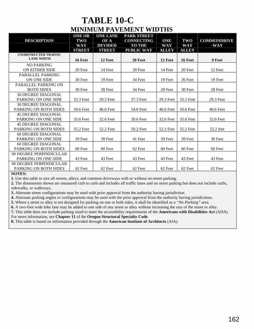
162
TABLE 10-CMINIMUM PAVEMENT WIDTHS
DESCRIPTIONONE OR
TWOWAY
STREET
ONE LANEOF A
DEVIDEDSTREET
PARK STREETCONNECTING
TO THEPUBLIC WAY
ONEWAY
ALLEY
TWOWAY
ALLEY
COMMONDRIVE-WAY
UNOBSTRUCTED TRAFFIC LANE WIDTH 16 Feet 12 Feet 20 Feet 12 Feet 16 Feet 9 Feet
NO PARKINGON EITHER SIDE 20 Feet 14 Feet 30 Feet 14 Feet 20 Feet 12 Feet
PARALLEL PARKINGON ONE SIDE 30 Feet 19 Feet 34 Feet 19 Feet 26 Feet 19 Feet
PARALLEL PARKING ONBOTH SIDES 30 Feet 28 Feet 34 Feet 28 Feet 30 Feet 28 Feet
30 DEGREE DIAGONALPARKING ON ONE SIDE 33.3 Feet 29.3 Feet 37.3 Feet 29.3 Feet 33.3 Feet 29.3 Feet30 DEGREE DIAGONAL
PARKING ON BOTH SIDES 50.6 Feet 46.6 Feet 54.6 Feet 46.6 Feet 50.6 Feet 46.6 Feet45 DEGREE DIAGONALPARKING ON ONE SIDE 35.6 Feet 32.6 Feet 39.6 Feet 32.6 Feet 35.6 Feet 32.6 Feet45 DEGREE DIAGONAL
PARKING ON BOTH SIDES 55.2 Feet 52.2 Feet 59.2 Feet 52.2 Feet 55.2 Feet 52.2 feet60 DEGREE DIAGONALPARKING ON ONE SIDE 39 Feet 39 Feet 41 Feet 39 Feet 39 Feet 39 Feet60 DEGREE DIAGONAL
PARKING ON BOTH SIDES 60 Feet 60 Feet 62 Feet 60 Feet 60 Feet 60 Feet90 DEGREE PERPINDICULAR
PARKING ON ONE SIDE 43 Feet 43 Feet 43 Feet 43 Feet 43 Feet 43 Feet90 DEGREE PERPINDICULAR
PARKING ON BOTH SIDES 62 Feet 62 Feet 62 Feet 62 Feet 62 Feet 62 FeetNOTES:1. Use this table to size all streets, alleys, and common driveways with or without on-street parking.2. The dimensions shown are measured curb to curb and includes all traffic lanes and on street parking but does not include curbs,sidewalks, or walkways.3. Alternate street configurations may be used with prior approval from the authority having jurisdiction.4. Alternate parking angles or configurations may be used with the prior approval from the authority having jurisdictions.5. Where a street or alley is not designed for parking on one or both sides, it shall be identified as a “No Parking” area.6. A two-foot wide bike lane may be added to one side of any street or alley without increasing the size of the street or alley.7. This table does not include parking sized to meet the accessibility requirements of the Americans with Disabilities Act (ADA).For more information, see Chapter 11 of the Oregon Structural Specialty Code.8. This table is based on information provided through the American Institute of Architects (AIA).
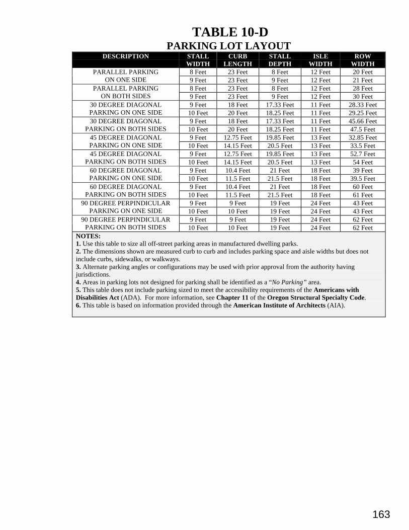
163
TABLE 10-DPARKING LOT LAYOUT
DESCRIPTION STALLWIDTH
CURBLENGTH
STALLDEPTH
ISLEWIDTH
ROWWIDTH
8 Feet 23 Feet 8 Feet 12 Feet 20 FeetPARALLEL PARKINGON ONE SIDE 9 Feet 23 Feet 9 Feet 12 Feet 21 Feet
8 Feet 23 Feet 8 Feet 12 Feet 28 FeetPARALLEL PARKINGON BOTH SIDES 9 Feet 23 Feet 9 Feet 12 Feet 30 Feet
9 Feet 18 Feet 17.33 Feet 11 Feet 28.33 Feet30 DEGREE DIAGONALPARKING ON ONE SIDE 10 Feet 20 Feet 18.25 Feet 11 Feet 29.25 Feet
9 Feet 18 Feet 17.33 Feet 11 Feet 45.66 Feet30 DEGREE DIAGONALPARKING ON BOTH SIDES 10 Feet 20 Feet 18.25 Feet 11 Feet 47.5 Feet
9 Feet 12.75 Feet 19.85 Feet 13 Feet 32.85 Feet45 DEGREE DIAGONALPARKING ON ONE SIDE 10 Feet 14.15 Feet 20.5 Feet 13 Feet 33.5 Feet
9 Feet 12.75 Feet 19.85 Feet 13 Feet 52.7 Feet45 DEGREE DIAGONALPARKING ON BOTH SIDES 10 Feet 14.15 Feet 20.5 Feet 13 Feet 54 Feet
9 Feet 10.4 Feet 21 Feet 18 Feet 39 Feet60 DEGREE DIAGONALPARKING ON ONE SIDE 10 Feet 11.5 Feet 21.5 Feet 18 Feet 39.5 Feet
9 Feet 10.4 Feet 21 Feet 18 Feet 60 Feet60 DEGREE DIAGONALPARKING ON BOTH SIDES 10 Feet 11.5 Feet 21.5 Feet 18 Feet 61 Feet
9 Feet 9 Feet 19 Feet 24 Feet 43 Feet90 DEGREE PERPINDICULARPARKING ON ONE SIDE 10 Feet 10 Feet 19 Feet 24 Feet 43 Feet
9 Feet 9 Feet 19 Feet 24 Feet 62 Feet90 DEGREE PERPINDICULARPARKING ON BOTH SIDES 10 Feet 10 Feet 19 Feet 24 Feet 62 Feet
NOTES:1. Use this table to size all off-street parking areas in manufactured dwelling parks.2. The dimensions shown are measured curb to curb and includes parking space and aisle widths but does notinclude curbs, sidewalks, or walkways.3. Alternate parking angles or configurations may be used with prior approval from the authority havingjurisdictions.4. Areas in parking lots not designed for parking shall be identified as a “No Parking” area.5. This table does not include parking sized to meet the accessibility requirements of the Americans withDisabilities Act (ADA). For more information, see Chapter 11 of the Oregon Structural Specialty Code.6. This table is based on information provided through the American Institute of Architects (AIA).
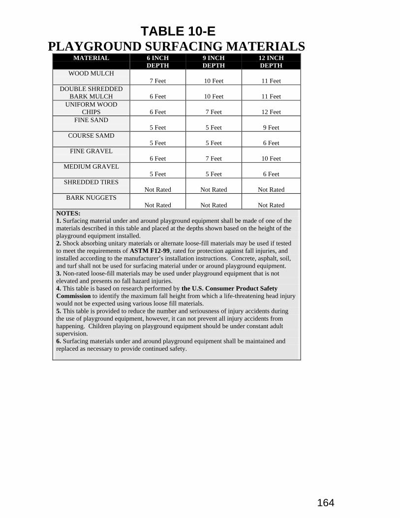
164
TABLE 10-EPLAYGROUND SURFACING MATERIALS
MATERIAL 6 INCHDEPTH
9 INCHDEPTH
12 INCHDEPTH
WOOD MULCH7 Feet 10 Feet 11 Feet
DOUBLE SHREDDEDBARK MULCH 6 Feet 10 Feet 11 Feet
UNIFORM WOODCHIPS 6 Feet 7 Feet 12 Feet
FINE SAND5 Feet 5 Feet 9 Feet
COURSE SAMD5 Feet 5 Feet 6 Feet
FINE GRAVEL6 Feet 7 Feet 10 Feet
MEDIUM GRAVEL5 Feet 5 Feet 6 Feet
SHREDDED TIRESNot Rated Not Rated Not Rated
BARK NUGGETSNot Rated Not Rated Not Rated
NOTES:1. Surfacing material under and around playground equipment shall be made of one of thematerials described in this table and placed at the depths shown based on the height of theplayground equipment installed.2. Shock absorbing unitary materials or alternate loose-fill materials may be used if testedto meet the requirements of ASTM F12-99, rated for protection against fall injuries, andinstalled according to the manufacturer’s installation instructions. Concrete, asphalt, soil,and turf shall not be used for surfacing material under or around playground equipment.3. Non-rated loose-fill materials may be used under playground equipment that is notelevated and presents no fall hazard injuries.4. This table is based on research performed by the U.S. Consumer Product SafetyCommission to identify the maximum fall height from which a life-threatening head injurywould not be expected using various loose fill materials.5. This table is provided to reduce the number and seriousness of injury accidents duringthe use of playground equipment, however, it can not prevent all injury accidents fromhappening. Children playing on playground equipment should be under constant adultsupervision.6. Surfacing materials under and around playground equipment shall be maintained andreplaced as necessary to provide continued safety.
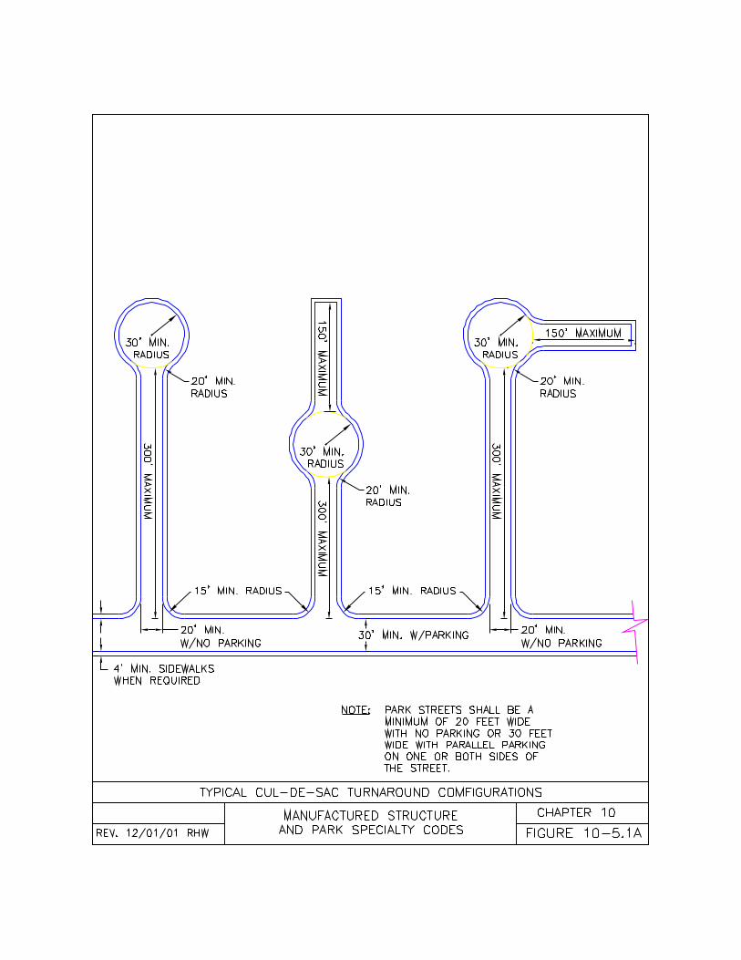
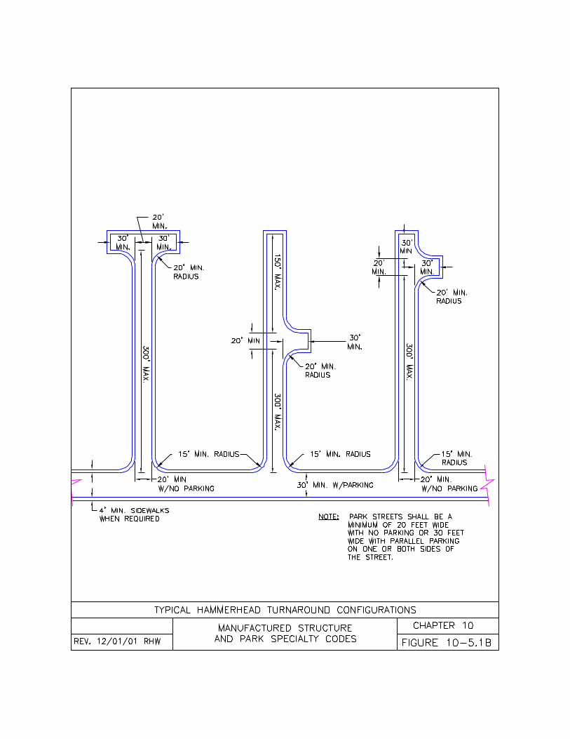
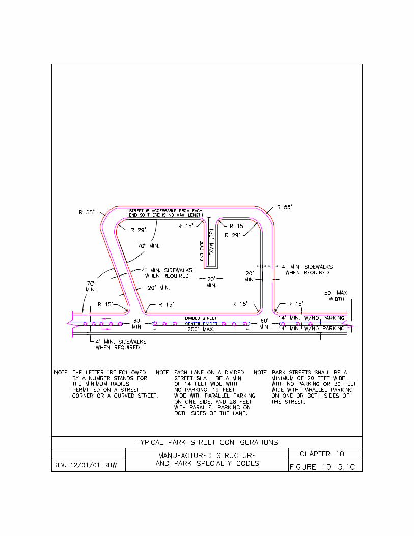
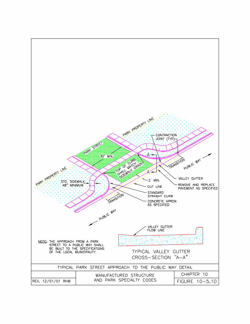
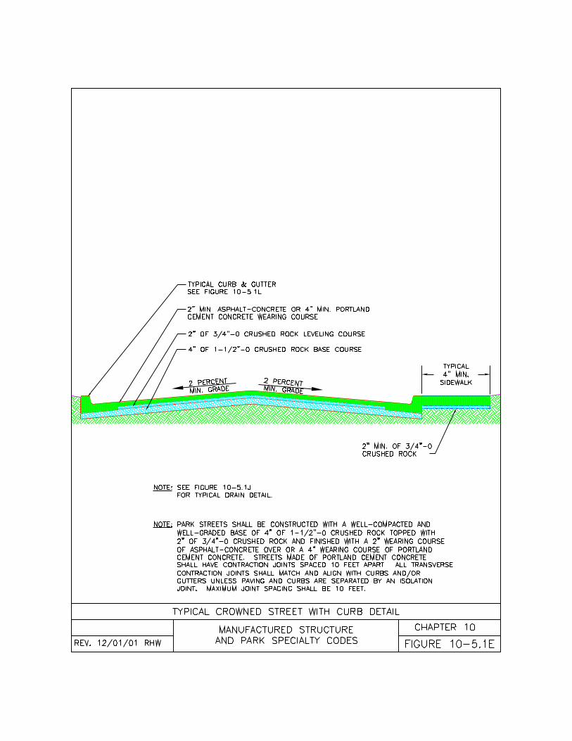
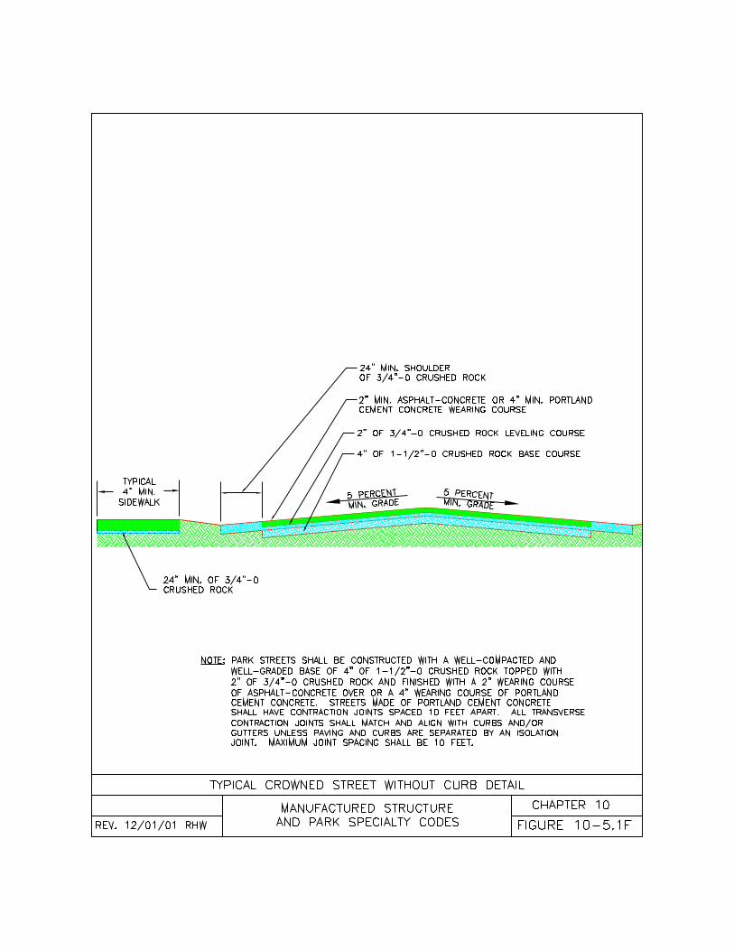
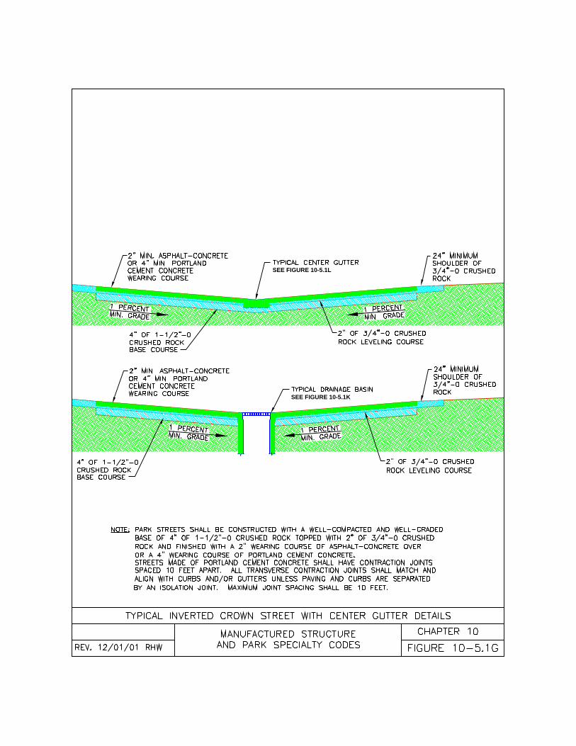
SEE FIGURE 10-5.1L
SEE FIGURE 10-5.1K
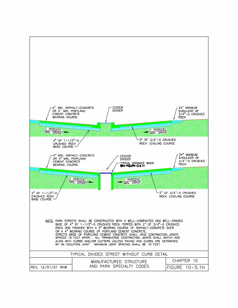
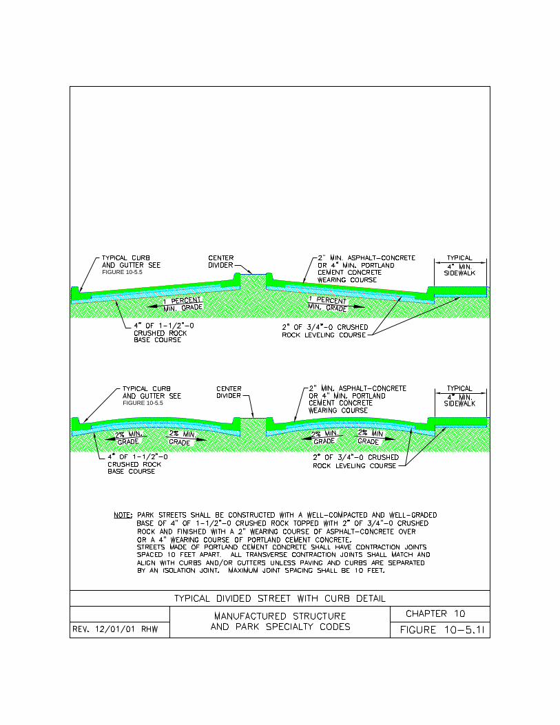
FIGURE 10-5.5
FIGURE 10-5.5
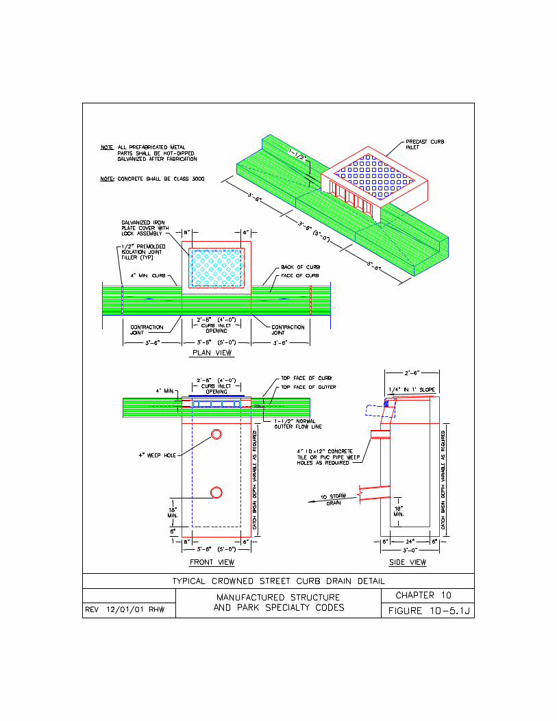
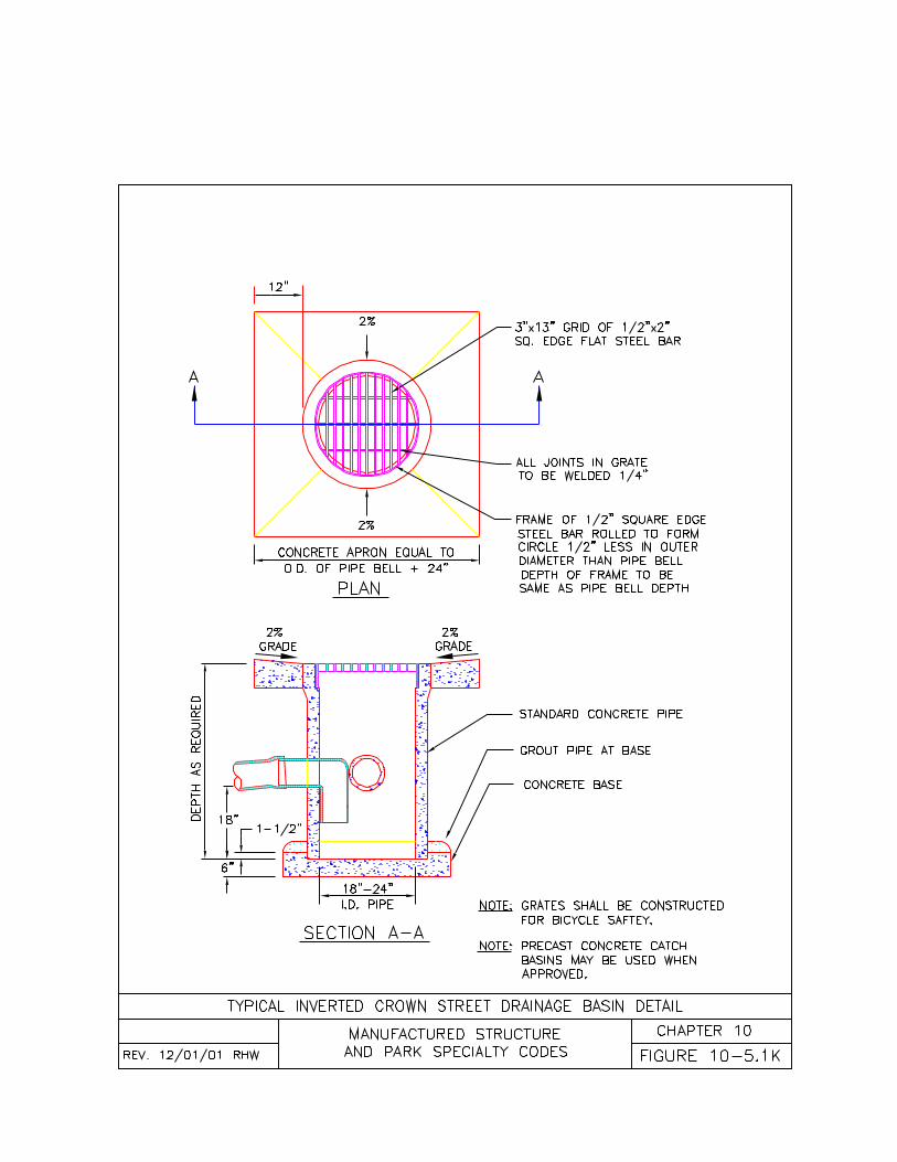
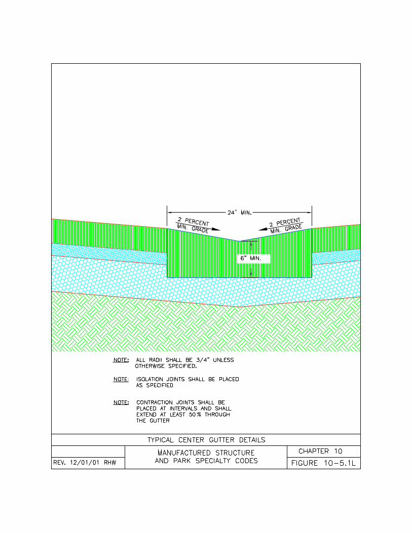
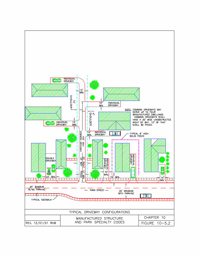
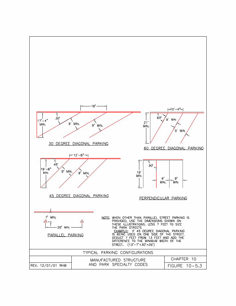
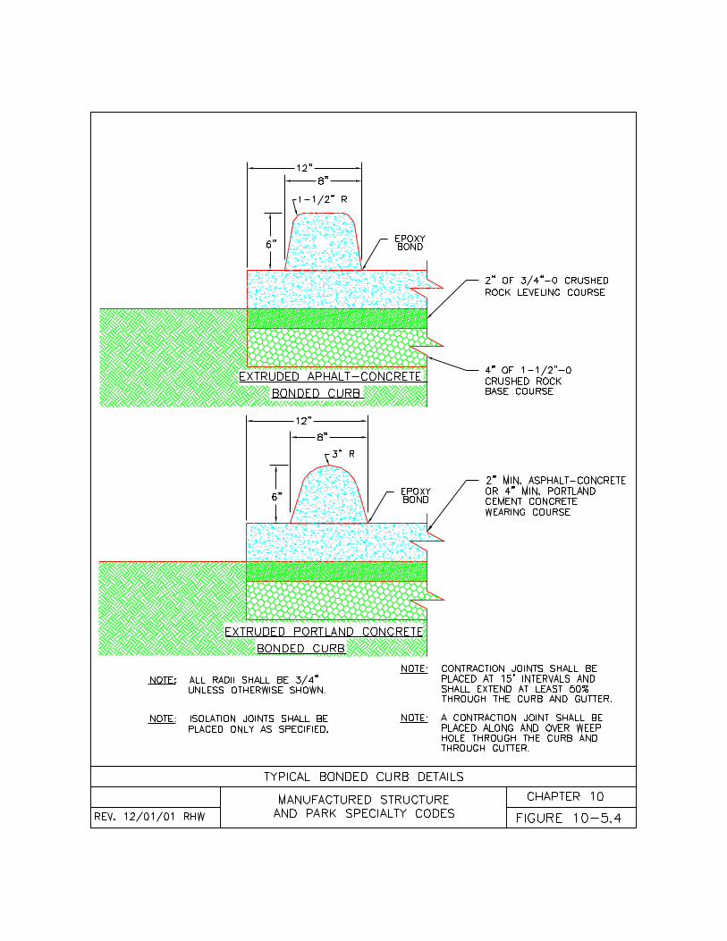
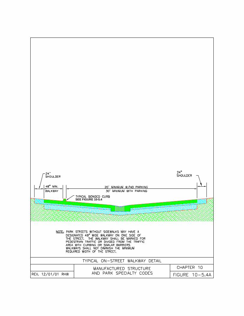
SEE FIGURE 10-5.4
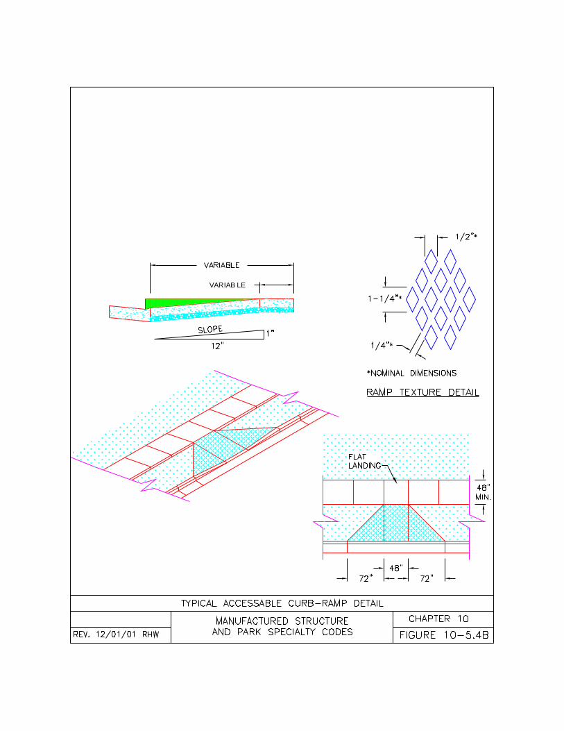
VARIABLE
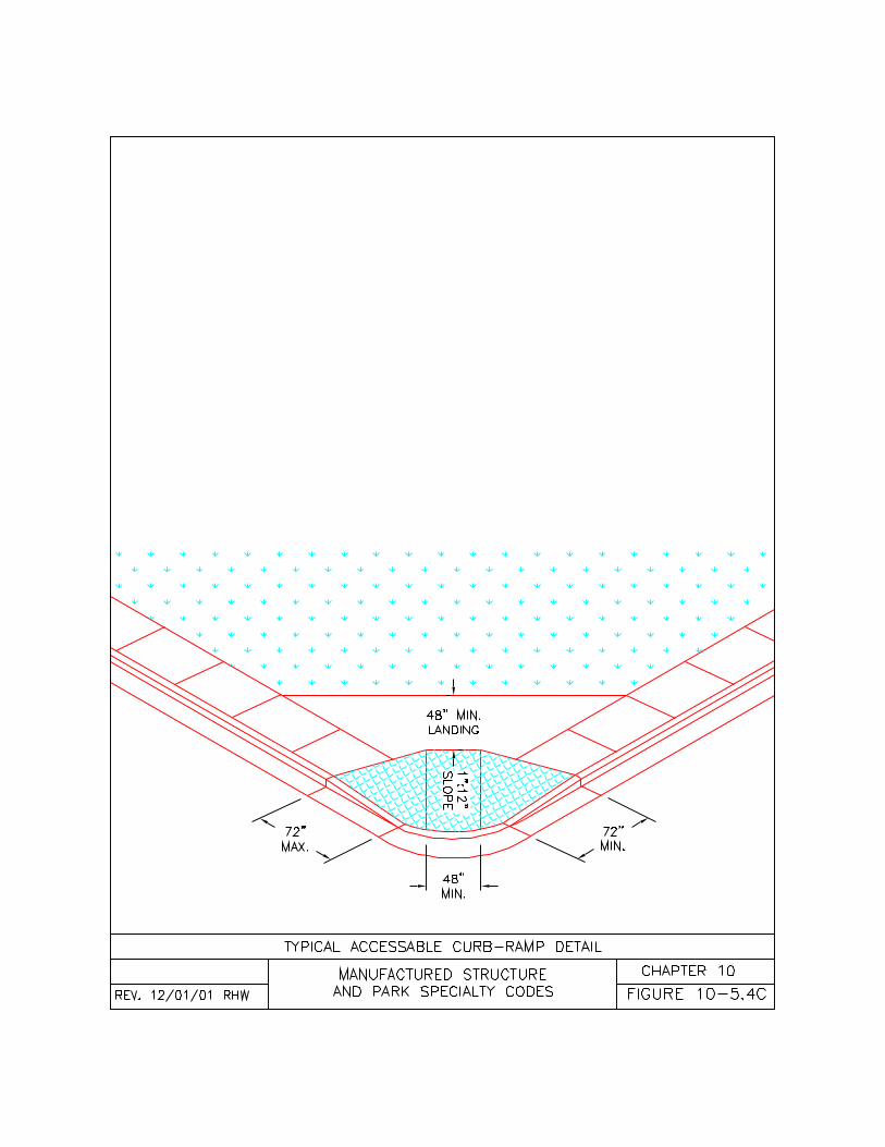
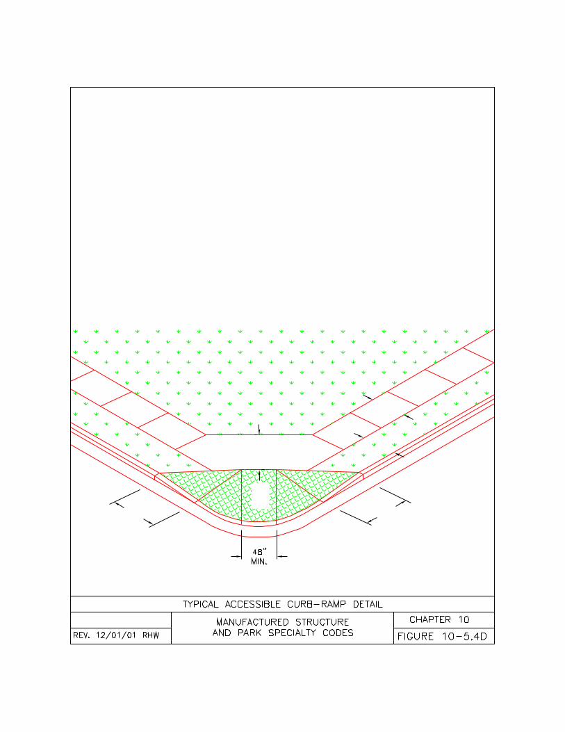
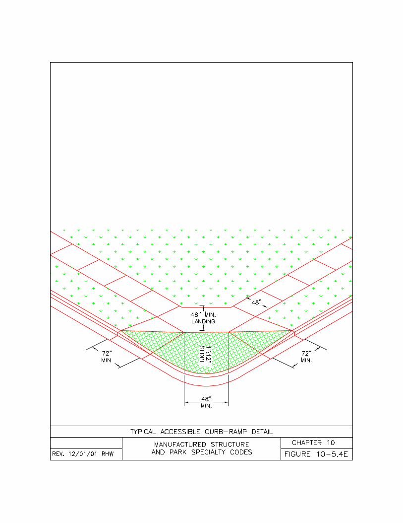
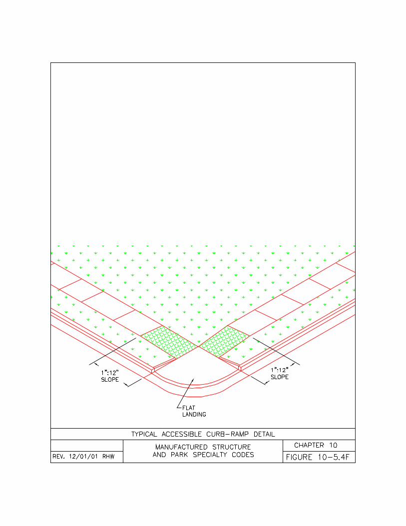
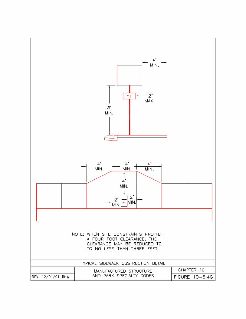
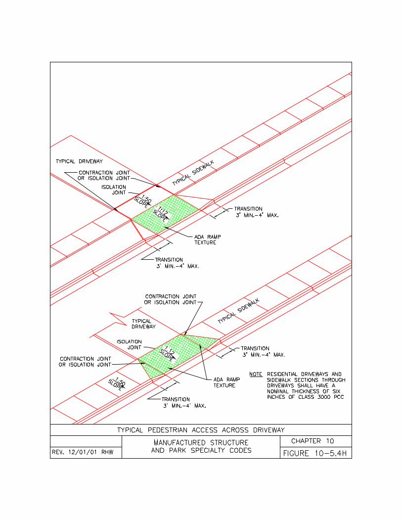
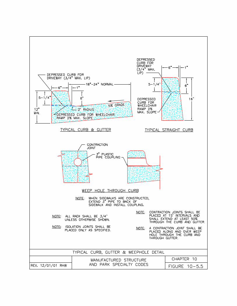
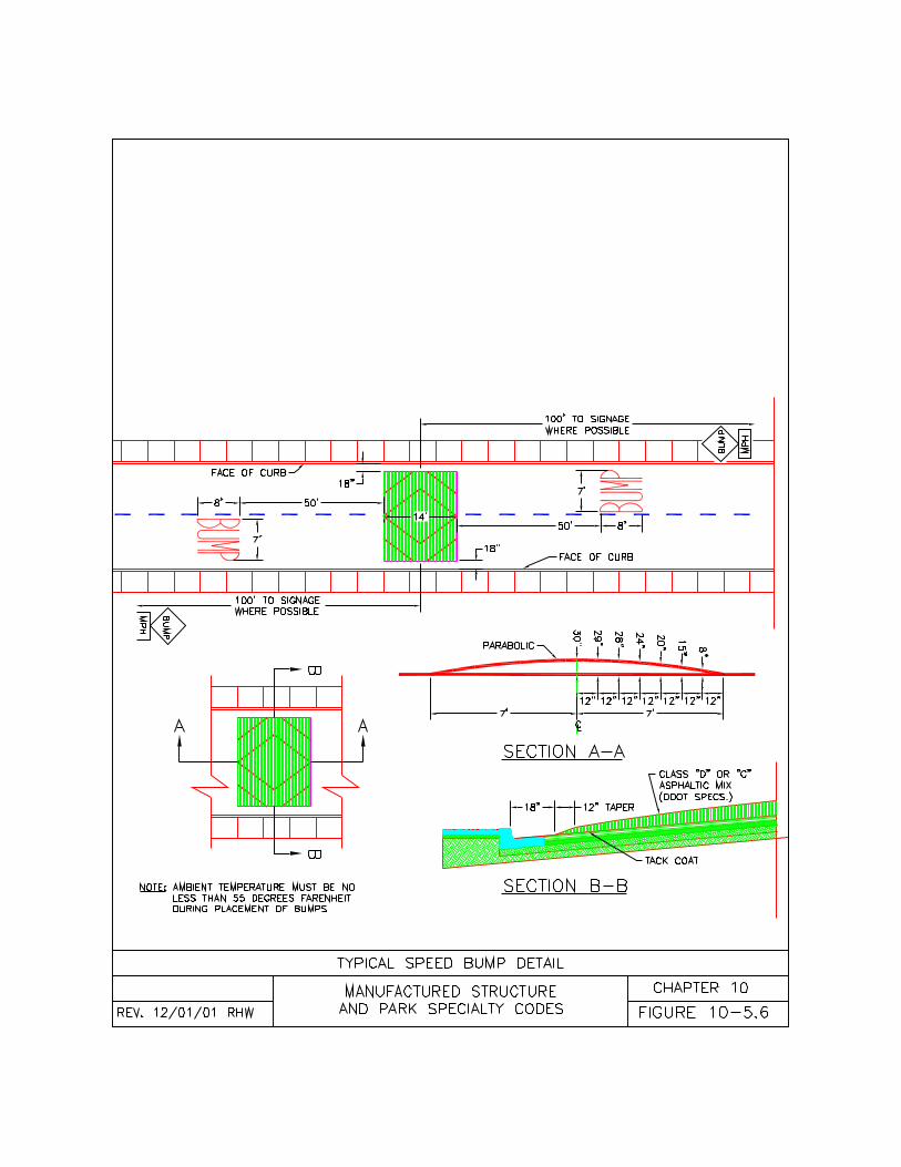
165
Appendix A
DEFINITIONS
This code uses terminology unique to the manufactured dwelling and construction industry. The following areexplanations of the terminology used in this code as derived from several recognized sources. Unlessotherwise expressly stated, the following definitions shall, for the purpose of this code, have the meaningsindicated in this appendix. Definitions quoted from other documents are from the most recent publication ofthose documents at the time this code was printed. Where terms are not defined in this code, such termsshall have the meanings ascribed to them in the reference standards. Where terms are not defined in eitherthis code or the referenced standards, such terms shall have their ordinary accepted meanings within thecontext with which they are used according to Webster’s Third New International Dictionary of the EnglishLanguage, Unabridged, Copyright 1986.
• “Accessible” has the following meanings:• “Accessible”, as defined in NFPA 501-1999, means able to approach, access a fixture, connection,
appliance, or equipment. Access shall be permitted to require the removal of an access panel, door,or similar obstruction.
• “Accessible, Readily”, as defined in NFPA 501-1999, means direct access without the necessity ofremoving any panel, door, or similar obstruction.
• “Accessibility”, as it relates to ORS 447.210, means the removal of architectural barriers for thepurpose of providing full access to persons with disabilities.
• “Accessory Building or Structure”, as defined in ORS 446.003, means any portable, demountable orpermanent structure established for use of the occupant of the manufactured structure and as furtherdefined by rule by the director.• “Accessory Building”, as defined in OAR 918-500-0005, means an accessory building as defined
in ORS 446.003(1) and specifically includes but is not limited to cabanas, ramadas, storage sheds,garages, and basements.
• “Accessory Structures”, as defined in OAR 918-500-0005, means an accessory structure asdefined in ORS 446.003(1) and specifically includes but is not limited to awnings, carports, decks,steps and ramps.
• “Adjustment of Equipment”, as defined in OAR 918-500-0005, means the adjustment of the rate, flow,speed, temperature, etc. as necessary for the continued operation of the equipment but does not includethe repair, replacement, conversion, alteration or addition to any equipment.
• “Affected Buildings”, as defined in ORS 447.210, includes any place of public accommodations andcommercial facilities designed, constructed and altered in compliance with the accessibility standardsestablished by the Americans with Disabilities Act. “Affected Buildings” also includes any governmentbuilding that is subject to Title II of the Americans with Disabilities Act. “Affected Buildings” alsoincludes private entities, private membership clubs and churches that have more than one floor level andmore than 4,000 square feet in ground area or that are more than 20 feet in height, measured from thetop surface of the lowest flooring to the highest interior overhead finish of the building. (See definition ofcommercial facilities.)
• “Air conditioner”, as defined in NFPA 501-1999, means all equipment intended or installed for thepurpose of processing the treatment of air so as to control simultaneously its temperature, humidity,cleanliness, and distribution to meet the requirements of the conditioned space. (does not includeevaporative coolers)
• “Alteration”, as defined in ORS 446.003, means any change, addition, repair, conversion, replacement,modification or removal of any equipment or installation which may affect the operation, construction oroccupancy of a manufactured structure.• “Alteration” does not mean:
• Minor repairs with approved component parts;• Conversion of listed fuel burning appliances in accordance with the terms of their listing; or• Adjustment and maintenance of equipment; or replacement of equipment or accessories in
kind. (See definition of replacement in kind)• “Anchoring System”, as defined in OAR 918-500-0005, means the equipment or materials used to
secure a manufactured home to the ground.• “Approved”, as defined in ORS 446.003, means approved, licensed or certified by the Department of
Consumer and Business Services or its designee.
166
• “Attached Garage”, as defined in OAR 918-500-0005, means a garage which is designed to bestructurally independent of a manufactured dwelling but may be attached to a manufactured dwellingaccording to this code.
• “Authority Having Jurisdiction”, as defined in OAR 918-500-0005, means the Building Codes Divisionor local government which has been appointed by the Administrator to inspect and issue permits forinstallation, alteration or conversion of manufactured dwellings, equipment, accessory buildings andstructures.
• “Awning”, as defined in ORS 446.003, means any stationary structure, permanent or demountable,used in conjunction with a manufactured structure, other than window awning, for the purpose ofproviding shelter from the sun and rain, and having a roof with supports and not more than one wall orstorage cabinet substituting for a wall. (also known as a patio cover)
• “Base Flood”, as defined in 44 CFR Chapter 1, means the flood having a one percent chance of beingequaled or exceeded in any given year.
• “Board”, as defined in ORS 446.003, means the Manufactured Structures and Parks Advisory Board.• “Bonding”, as defined in NFPA 501-1999, means the permanent joining of metallic parts to form an
electrically conductive path that will ensure electrical continuity and the capacity to conduct safely anycurrent likely to be imposed.
• “Breakaway Wall”, as defined in 44 CFR Chapter 1, means a wall that is not part of the structuralsupport of the building and is intended through its design and construction to collapse under specificlateral loading forces, without causing damage to the elevated portion of the building or supportingfoundation system.
• “Building”, as defined in OAR 918-500-0005, means any permanent building but does not includemanufactured dwellings or manufactured dwelling accessory buildings.
• “Building Drain”, as defined in the OAR 918-500-0005, means that part of the lowest piping of adrainage system which receives the discharge from soil, waste and other drainage pipes inside the wallsof the manufactured dwelling and conveys it to the building sewer.
• “Building Sewer”, as defined in the Oregon One and Two Family Dwelling Specialty Code, meansthat part of the horizontal piping of a drainage system which extends from the end of the building drainand which receives the discharge of the building drain and conveys it to a public sewer, private sewer,individual sewage disposal system, or other point of disposal.
• “Building Supply”, as defined in the Oregon One and Two Family Dwelling Specialty Code, meansthe pipe carrying potable water from the water meter or other source of water supply to a building orother point of use or distribution on the lot. Building supply shall also mean water service.
• “Cabana”, as defined in ORS 446.003(6), means a stationary, light-weight structure which may beprefabricated or demountable, with two or more walls, used adjacent to and in conjunction with amanufactured structure to provide additional living space.
• “Carport”, as defined in ORS 446.003, means a stationary structure consisting of a roof with itssupports and not more than one wall, or storage cabinet substituting for a wall, and used for sheltering amotor vehicle.
• “Chassis”, as defined in NFPA 501-1999, means the entire transportation system comprising thefollowing subsystems: drawbar and coupling mechanism, frame, running gear assembly, and lights.
• “Clearance”, as defined in OAR 918-500-0005, means the minimum allowable distance between twoadjacent surfaces or points.
• “Combination Park”, as defined in OAR 918-500-0005, means a lot or tract of land that has beenapproved to contain both a manufactured dwelling or mobile home park and a recreation park.
• “Combustible Material”, as defined in NFPA 501-1999, means any material not meeting the definitionof limited-combustible or noncombustible material in Section 3.2 of NFPA 501-1999.
• “Comfort Cooling Equipment”, as defined in NFPA 501-1999, means all equipment intended orinstalled for the purpose of processing the treatment of air so as to control simultaneously itstemperature, humidity, cleanliness, and distribution to meet the requirements of the conditioned space.(does not include evaporative coolers)
• “Commercial Facilities”, as defined in ORS 447.210, includes non-residential facilities, such as officebuildings, factories, and warehouses, whose operations affect commerce.
• “Concealed”, as defined in OAR 918-500-0005, means rendered inaccessible by the structure or finishof the manufactured dwelling, accessory building, or accessory structure.
• “Conversion” or “to convert”, as defined in ORS 446.003(9), means the process of changing amanufactured structure in whole or in part from one type of vehicle or structure to another.
• “DAPIA” means a state or private organization that has been accepted by the Secretary of HUD toevaluate and approve manufactured home designs and quality control procedures.
167
• “Decorative Appliance”, as defined in NFPA 54-1999, means a self-contained, freestanding, fuel-gasburning appliance designed for installation only in a vented fireplace and whose primary function lies inthe aesthetic effect of the flame.
• “Direct Supervision”, as defined in OAR 918-500-0005, means being physically present 85 percent ofeach day to provide leadership and direction on the job site to limited installers installing manufactureddwellings.
• “Direct Vent”, as defined in NFPA 54-1999, means appliances that are constructed and installed so thatall air for combustion is derived directly from the outside atmosphere and all flue gases are discharged tothe outside atmosphere.
• “Drain”, as defined in NFPA 501-1999, means a pipe that carries waste, water, or water-borne waste ina drainage system.
• “Drain Connector”, as defined in NFPA 501-1999, means the removable extension, consisting of allpipes, fittings, and appurtenances, from the drain outlet to the drain inlet serving the manufactured home.
• “Drain, Main”, as defined in NFPA 501-1999, means the lowest pipe of a drainage system that receivessewage from all the fixtures within a manufactured home and conducts these wastes to the drain outlet.
• “Drain Outlet”, as defined in NFPA 501-1999, means the lowest end of the main or secondary drain towhich a sewer connection is made.
• “Drainage System”, as defined in NFPA 501-1999, means all piping, within or attached to the structure,that conveys sewage or other liquid waste to the drain outlet, not including the drain connector.
• “Dwelling Unit”, as defined in NFPA 501-1999, means one or more habitable rooms, designed to beoccupied by one or more persons, with facilities for living, sleeping, cooking, and eating.
• “Earthquake-Resistant Bracing System”, as defined in OAR 918-500-0005, means a certified andapproved anchoring, bracing, or support system designed and constructed to protect the health andsafety of the occupants of, and reducing damage to, a manufactured dwelling in the event of anearthquake.
• “Engineered Foundation System”, as defined in OAR 918-500-005, means a certified and approvedengineered system of prefabricated foundation supports installed to manufacturer’s installationinstructions. (formerly known as a “Full Foundation System)
• “EPDM” means ethylene propylene diolefin monomer, a rubber sheeting used to prevent waterpenetration in roofing, foundations and other similar applications where moisture or water penetrationmust be eliminated or minimized.
• “Equipment”, as defined in ORS 446.003, means materials, appliances, subassembly, devices, fixtures,fittings and apparatuses used in the construction, plumbing, mechanical and electrical systems of amanufactured structure.
• “Factory Built Porch”, as defined in OAR 918-500-0005, means an exterior porch, deck, or landing,including roof, built by the manufactured dwelling manufacturer and shipped with the manufactureddwelling.
• “Feeder Assembly”, as defined in NFPA 501-1999, means the overhead or under-chassis feederconductors, including the grounding conductor, together with the necessary fittings and equipment, or apower supply cord approved for manufactured home use, that are designed for the purpose of deliveringenergy from the source of electrical supply to the distribution panel board within the manufactured home.
• “Field Technical Service”, as defined in OAR 918-500-0005, means the clarification of technical data,including, but not limited to, Division interpretations, investigations or training relating to the application oflaws, rules, codes, standards and regulations administered and enforced by the Building Codes Division.
• “Fill”, as defined in OAR 918-500-0005, means a man made deposit of materials intended to raise anexisting grade and includes the following types:• “Engineered Fill”, means fill over 12 inches in depth placed in layers of soil, crushed stone, or
masonry waste material, free of expansive soils and organic materials, compacted and testedaccording to accepted engineering practices to insure that it meets the required load bearingcapacity and specified compaction standards as determined by laboratory tests of soil samples fromthe fill material.
• “Non Engineered Fill”, means fill of 12 inches or less in depth consisting of soil, crushed stone, ormasonry waste material, free of expansive soils and organic materials, compacted with two passesof a vibrating compacting machine.
• “Fill” does not include the 6 inches of gravel required on some manufactured dwelling stands.• “Fireplace”, as defined in NFPA 54-1999, means a fire chamber and hearth constructed of
noncombustible material for use with solid fuels and provided with a chimney.• “Fireplace, Masonry”, as defined in NFPA 54-1999, means a hearth and fire chamber of solid
masonry units such as bricks, stones, listed masonry units, or reinforced concrete, provided with asuitable chimney.
168
• “Fireplace, Factory-Built”, as defined in NFPA 501-1999, means a hearth, fire chamber, andchimney assembly composed of listed factory-build components assembled in accordance with theterms of listing to form a complete fireplace.
• “Fireplace Stove”, as defined in NFPA 501-1999, means a chimney connected solid fuel-burningstove having part of its fire chamber open to the room.
• “Flood Hazard Area”, as defined in 44 CFR Chapter 1, means all zones identified on the FEMA’s FloodInsurance Rate Map.
• “Flood Insurance Rate Map or FIRM”, as defined in 44 CFR Chapter 1, means an official map of acommunity, on which FEMA has delineated both the special hazard areas and the risk premium zonesapplicable to the community.
• “Flood Plain”, as defined in 44 CFR Chapter 1, means any land area susceptible to being inundated bywater from any source.
• “Flood Way”, as defined in 44 CFR Chapter 1, means the channel of a river or other water course andthe adjacent land areas that must be reserved in order to discharge the base flood without cumulativelyincreasing the water surface elevation more than a designated height.
• “Footing”, as defined in NFPA 501-1999, means that portion of the support system that transmits loadsdirectly to the soil.
• “Foundation Wall”, as defined in OAR 918-500-0005, means concrete, block, or wood stem wallsupporting the perimeter of the manufactured dwelling.
• “Frame”, as defined in NFPA 501-1999, means the fabricated, rigid substructure which providesconsiderable support to the affixed manufactured home structure, both during transport and on-site; andalso provides a platform for securement of the running gear assembly, the draw bar, and couplingmechanism.
• “Garage”, as defined in OAR 918-500-0005, means a structure located on a manufactured dwelling sitedesigned for the storage of motor vehicles.
• “Gas Supply Connector”, as defined in NFPA 501-1999, means a listed flexible connector designed toconnect the manufactured home to the gas supply source.
• “Grade” has the following meanings:• “Grade”, as it relates to plumbing and as defined in NFPA 501-1999, means the fall (slope) of a pipe
in reference to a horizontal plane expressed in inches per foot length (millimeters per meters).• “Grade”, as it relates to the earth and as defined in Oregon One and Two Family Dwelling
Specialty Code, means the finished ground level adjoining the building at all exterior walls.• “Ground”, as defined in NFPA 501-1999, means a conductive connection, whether intentional or
accidental, between an electrical circuit or equipment and earth, or through some conducting body thatserves in place of the earth.
• “Grounded”, as defined in NFPA 501-1999, means connected to earth, or to some conducting body thatserves in place of the earth.
• “Ground Anchor”, as defined in NFPA 501-1999, means any device at a manufactured home standdesigned to transfer manufactured home anchoring loads to the ground.
• “Ground Level Installation”, as defined in OAR 918-500-0005, means a manufactured dwelling with abelow-grade foundation system and a perimeter retaining wall or foundation which is back filled againstit.
• “Habitable Area”, as defined in OAR 918-500-0005, means an indoor area intended for humanhabitation consist of, but not be limited to, areas used for living, eating, cooking, sleeping, or recreationalpurposes.
• “Habitable Room”, as defined in NFPA 501-1999, means a room or an enclosed floor space intendedfor living, eating, food preparation, or sleeping purposes, not including bathrooms, foyers, hallways, andother accessory floor spaces.
• “Heating Appliance”, as defined in NFPA 501-1999, means an appliance for comfort heating or fordomestic water heating.
• “Heat-Producing Appliance”, as defined in NFPA 501-1999, means all heating and cooking appliancesand fuel burning appliances.
• “Heat Pump”, as defined in NFPA 54-1999, means an automatically operated appliance utilizing arefrigeration system for supplying either heated air or liquid, or heated and/or cooled air or liquid.
• “Immediate Family” as defined in OAR 918-500-0005, means father, mother, brother, sister, son,daughter, son-in-law, daughter-in-law, grandson, granddaughter, grandfather, grandmother, stepmother,stepfather, stepson, stepdaughter, brother-in-law, or sister-in-law.
• “Installation”, as defined in ORS 446.003, in relation to:• “Construction” means the arrangements and methods of construction, fire and life safety, electrical,
plumbing and mechanical equipment and systems within a manufactured structure.
169
• “Siting” means the manufactured structure and cabana foundation support and tie-down, thestructural, fire and life safety, electrical, plumbing and mechanical equipment and materialconnections and the installation of skirting and temporary steps.
• “Insignia”, as defined in ORS 446.003 means:• For a manufactured dwelling built to the HUD standards for such a dwellings, the HUD label; or• For all other manufactured structures, the insignia issued by this state indicating compliance with
state law.• “Installer”, as defined in ORS 446.003, means any individual licensed by the director to install, set up,
connect, hook up, block, tie down, secure, support, install temporary steps, install skirting for or makeelectrical, plumbing or mechanical connections to manufactured dwellings or cabanas or who providesconsultation or supervision for any of these activities, except architects licensed under ORS 671.010 to671.220 or engineers licensed under ORS 672.002 to 672.325.
• “IPIA” means a state or private organization that has been accepted by the Secretary of HUD toevaluate the ability of manufactured home manufacturers to follow approved quality control proceduresand provide ongoing surveillance of the manufacturing process.
• “Labeled”, as defined in OAR 918-500-0005, means equipment or materials used in the manufacture orinstallation of a manufactured dwelling, to which has been attached a label, symbol or other identifyingmark of a nationally recognized testing laboratory, inspection agency or other organization whichevaluates products to nationally recognized standards and periodically inspects production of equipmentand materials to show compliance with those standards for usage in a specified manner.
• “Listing Agency” as defined in OAR 918-500-0005, means an agency that: Is regularly engaged inconducting its own tests, listing, labeling or contracting its testing procedures to a nationally recognizedtesting agency; Maintains a periodic inspection program on production of currently listed products; andPublishes, at a minimum, an annual report which is used to determine whether products have beentested to such national standards and found safe for use in a specified manner.
• “Load Bearing Device”, as defined in OAR 918-500-0005, means any equipment or device used in thesupport of a manufactured dwelling including but not limited to footings, piers, caps and shims.
• “Load, Dead”, as defined in NFPA 501-1999, means the weight of all permanent construction, includingwalls, floors, roof, partitions, and fixed service equipment.
• “Load, Live”, as defined in NFPA 501-1999, means the weight superimposed by the use andoccupancy of the manufactured home, including wind load and snow load, but not including dead load.
• “Load, Wind”, as defined in NFPA 501-1999, means the lateral or vertical pressure or uplift on themanufactured home due to wind blowing in any direction.
• “Lot”, as defined by statute in ORS 446.003, means any space, area or tract of land, or portion of amanufactured dwelling park or mobile home park, which is designated or used for occupancy by onemanufactured dwelling.
• “Park Lighting” terminology used in this code shall be based on the following definitions.• “Candela”, as defined by the International System of Units (SI), means the SI unit of luminous
intensity (formerly called the candle). One candela equals one lumen per steradian.• “Disability Glare”, as defined by the Northwest Lighting Industry Association, means glare
resulting in reduced visual performance and visibility often accompanied by discomfort glare.• “Discomfort Glare”, as defined by the Northwest Lighting Industry Association, means glare
producing discomfort but which does not necessarily interfere with visual performance of visibility.• “Footcandle”, as defined by the Northwest Lighting Industry Association, means a standard
measurement of illuminance, representing the amount of illuminance on a surface on foot square onwhich there is a uniformly distributed flus of one lumen.
• “Illuminance”, as defined by the Illuminating Engineering Society of North America, means thedensity of incident luminous flux on a surface. Illuminance is the standard metric for lighting levels,and is measured in lux (lx) or footcandles (fc).
• “Lumen”, as defined by the Illuminating Engineering Society of North America, means thequantity of luminous flux emitted within a unit solid angle (one steradian) by a point source with onecandela intensity in all directions.
• “Luminaire”, as defined by the Illuminating Engineering Society of North America, means acomplete lighting unit, consisting of a lamp or lamps together with the components required todistribute the light, position the lamps, and connect the lamps to a power supply (often referred to asa fixture).
• “Lx”, as defined in the International System of Units (SI), means the unit of illuminance equal toone lumen per square meter or 10,764 lx is equal to one foot candle.
• “Photocell”, as defined by the Illuminating Engineering Society of North America, means adevice that measures the amount of incident light present in a space.
170
• “Visual Comfort Probability (VCP)”, as defined by the Illuminating Engineering Society ofNorth America, means the rating of a lighting system expressed as a percentage of the people who,when viewing from a specified location and in a specified direction, will be expected to find itcomfortable in terms of discomfort glare.
• “Main Frame”, as defined in NFPA 501-1999, means the structural component on which the body of themanufactured home is mounted.
• “Maintenance of Equipment”, as defined in OAR 918-500-0005, means performing routine tasks suchas lubricating or changing filters, washers, fuses or bulbs as necessary for the continued operation of theequipment but does not include the replacement, conversion, alteration or addition of or to anyequipment.
• “Manufactured Dwelling” means a manufactured home, mobile home or residential trailer, as definedin ORS 446.003 (Manufactured dwelling does not mean any building or structure subject to the structuralspecialty code adopted pursuant to ORS 455.100 to 455.450 or any unit identified by the manufactureras a prefabricated structure, modular building, or recreational vehicle)
• “Manufactured Structure”, as defined in ORS 446.003, means a recreational vehicle (including parktrailers), a recreational structure, or manufactured dwelling. (Manufactured structure does not mean anybuilding or structure subject to the structural specialty code adopted pursuant to ORS 455.100 to455.450 or any unit identified by the manufacturer as a prefabricated structure or modular building)
• “Manufacturer’s Representative”, as defined in OAR 918-500-0005, means an employee, dealer orperson authorized by a manufacturer through contract to act on behalf of the manufacturer.
• “Minor Repair”, as defined in OAR 918-500-0005, means a simple repair such as replacing brokenglass, fittings, devices or fixtures, using approved component parts but does not include the repair orreplacement of major portions of the structural, plumbing, electrical or mechanical system orconversions, alterations or additions.
• “Model”, as defined in OAR 918-500-0005, means an individual manufactured structure, as designatedby the manufacturer, intended to be manufactured with a specific floor plan indicating a fixed location ofall walls, cabinets, structural components, and plumbing, mechanical and electrical equipment asapproved by the authority having jurisdiction.
• “Multiple”, as defined in OAR 918-500-0005, means two or more individual manufactured dwellingsdesigned to be adjoined with a zero clearance between them.
• “Municipality”, as defined in ORS 446.003, means a city, county or other unit of local governmentotherwise authorized by law to enact codes.
• “Noncompliance”, as defined in OAR 918-500-0005, means a failure of a manufactured dwelling,alteration or installation to comply with an appropriate building code.
• “Notice of Violation”, as defined in OAR 918-500-0005, means written notification by the Divisionstating the manufactured dwelling or equipment may not be used, rented, leased, or sold or offered forrent, lease, or sale due to violations of ORS Chapter 446 or the appropriate building code. (Also knownas, “Red Tag”, “Stop Work Order”, “Prohibited Sales Notice”).
• “Occupied Space”, as defined in the Oregon One and Two Family Dwelling Specialty Code, meansthe total area of all buildings or structures on any lot or parcel of ground projected on a horizontal plane,excluding permitted projections as allowed by this code.
• “Option”, as defined in OAR 918-500-0005 means a provision made during the manufacture of a hometo facilitate the future installation of any appliance or other equipment (e.g., air conditioner, wet bar ordishwasher).
• “Park Building”, as defined in OAR 918-500-0005, means any non residential building used for parkpurposes.
• “Park Street” or “Park Driveway”, as defined in OAR 918-500-0005, means a private way that affordsprincipal means of access to abutting individual manufactured dwelling lots and auxiliary buildings.
• “Park Trailer”, as defined in OAR 918-500-0005, means a vehicle built on a single chassis, mounted onwheels, designed to provide recreational, seasonal or temporary living quarters, and which has a grosstrailer area not exceeding 400 square feet in the set-up mode with all attachments. Such a vehicle maybe connected to utilities necessary for operation of installed fixtures and appliances and shall be referredto and identified by the manufacturer or converter as a recreational vehicle.
• “Pier”, as defined in NFPA 501-1999, means that portion of the support system between the footing andthe manufactured home, exclusive of caps and shims.
• “Play Area”, as defined in OAR 918-500-0005, means an area inside a park exclusively dedicated forchildren to play and exercise but does not include a park club house, pool, storage lot or other area setaside for the general use of the park residents.
• “Plenum”, as defined in NFPA 501-1999, means an air compartment that is part of an air-distributingsystem, to which one or more ducts or outlets are connected.
171
• “Porch”, as defined in NFPA 501A-1999, means an outside walking area having a floor that is elevatedmore than eight inches (203 mm) above grade.
• “Prefabricated Cabana”, as defined in OAR 918-500-0005, means a cabana built at an off site locationand transported to the site for installation.
• “Prefabricated Foundation System”, as defined in OAR 918-500-0005, means a listed or approvedengineered system of prefabricated foundation supports installed to the device manufacturer’sinstallation instructions.
• “Prefabricated Pier”, as defined in OAR 918-500-0005, means a listed or approved individual pierwhich is manufactured at an off site location but does not include concrete masonry units or earthquake-resistant bracing systems.
• “Public Way”, as defined in OAR 918-500-0005, means a public street, road, or hi-way providingaccess to a park.
• “Quick Disconnect Device”, as defined in NFPA 501-1999, means a hand-operated device whichprovides a means for connecting and disconnecting a gas supply or connecting gas systems, and whichis equipped with an automatic means to shut off the gas supply when the device is disconnected.
• “Ramada”, as defined in ORS 446.003, means a stationary structure having a roof extending over amanufactured structure, which may also extend over a patio or parking space for motor vehicles, and isused principally for protection from snow, sun or rain.
• “Readily Accessible”, see accessible.• “Recessed Porch”, as defined in OAR 918-500-0005, means an open floor area supported by the main
frame which is located outside the exterior walls of the manufactured dwelling which may be enclosed bya roof, three or less walls, screening or glass.
• “Regulator, Pressure”, as defined in NFPA 54-1999, means a device placed in a gas line for reducing,controlling, and maintaining the pressure that portion of the piping system downstream of the device.
• “Regulator, Service”, as defined in NFPA 54-1999, means a pressure regulator installed by the servinggas supplier to reduce and limit the service line gas pressure to the delivery pressure.
• “Repair”, as defined in OAR 918-500-0005, means the reconstruction or renewal of any part of anexisting manufactured dwelling or piece of equipment for the purpose of its maintenance (See alteration).
• “Replacement In Kind”, as defined in OAR 918-500-0005, means replacing equipment or accessorieswith approved like equipment or accessories, such as switches, thermostats, fittings, elements, ormotors, but does not include the replacement of major portions of the structural, plumbing, electrical, ormechanical system.
• “Roof Jack”, as defined in NFPA 501-1999, means that portion of a manufactured home heater flue orvent assembly, including the cap, insulating means, flashing, and ceiling plate, located in and above theroof of a manufactured home.
• “Room Heater, Vented”, as defined in NFPA 54-1999, means a vented self contained, free standingnon recessed, fuel –gas burning appliance for furnishing warm air to the space in which installed, directlyfor the heater without duct connections.
• “Running Gear Assembly”, as defined in NFPA 501-1999, means the subsystem consisting ofsuspension springs, axles, bearings, wheels, hubs, tires, and brakes, with their related hardware.
• “Sealed Combustion System Appliance”, as defined in NFPA 501-1999, means an appliance that byits inherent design is constructed so that all air supplied for combustion to the appliance’s combustionsystem, and all products of combustion are completely isolated from the atmosphere of the space whereit is installed.
• “Service Equipment, Manufactured Home”, as defined in NFPA 501-1999, means the equipmentcontaining the disconnecting means, over current protective devices and receptacles or other means forconnecting a manufactured home feeder assembly.
• “Set Up”, see the definition of installation.• “Single Family Dwelling”, as defined in OAR 918-500-0005, means a manufactured dwelling used by
an individual or two or more persons related by blood or marriage or a group of not more than tenpersons not related by blood or marriage living together. When located in a labor camp as defined inOAR 437-02-0142 (which the Building Codes Division adopted by reference as OAR 918-450-0005)single family dwelling shall include manufactured dwellings with not more than five bedrooms, used tohouse up to ten persons not related by blood or marriage.
• “Single Station Alarm Device”, as defined in NFPA 501-1999, means an assembly incorporating thesmoke detector sensor, the electrical control equipment, and the alarm-sounding device in one unit.
• “Site, Manufactured Dwelling”, as defined in OAR 918-500-0005, means a designated parcel of landdesigned to accommodate a manufactured dwelling, its accessory structures or buildings, and accessoryequipment for the exclusive use of the occupants.
• “Skirting”, as defined in ORS 446.003, means a weather resistant material used to enclose the spacebelow the manufactured structure.
172
• “Smoke Alarm”, as defined in ORS 479.250, means a self-contained single or multiple station detectiondevice for products of combustion other than heat that conforms to the state building code, rules of theState Fire Marshal and that is listed by Underwriters Laboratories or any other nationally recognizedtesting laboratory. “Smoke alarm” includes but is not limited to devices listed under UL 217 (1998).“Smoke alarm” may include two or more single station units wired to operate in conjunction with eachother.
• “Smoke Detector”, as defined in ORS 479.250, means a device that is not self contained, that detectsproducts of combustion other than heat, that is intended for use in conjunction with a central controlpanel, that conforms to the state building code and rules of the State Fire Marshal and that is listed byUnderwriters Laboratories or any other nationally recognized testing laboratory. “Smoke detector”includes but is not limited to devices listed under UL 268 (1998).
• “Stand”, as defined in OAR 918-500-0005, means that area of the manufactured dwelling site which hasbeen reserved for the placement of a manufactured dwelling or accessory structure.
• “Structure”, as defined in OAR 918-500-0005, means that which is built or constructed, an edifice orbuilding of any kind, or piece of work artificially built up or composed of parts joined together in somedefinite manner.
• “Substantial Damage”, as defined by FEMA in 44 CFR Chapter 1, means that the retail cost ofrepairing a dwelling up to code equals or exceeds 50 percent of the pre-damage market value of thedwelling (excluding land value).
• “Support System”, as defined in NFPA 501-1999, means a combination of footings, piers, caps, andshims that will, when properly installed, support the manufactured home.
• “Tag”, as defined in OAR 918-500-0005, means a label or insignia issued by the Division and applied tomanufactured dwellings to indicate compliance with federal or state laws, rules and regulations (Seeinsignia).
• “Testing Laboratory” or “Testing Agency”, as defined in OAR 918-500-0005, means an organization:In the business of testing equipment and systems; Qualified and equipped to perform or to observeexperimental testing to approved standards; Not under the jurisdiction or control of any singlemanufacturer or supplier for an affected industry; Which publishes reports including specified informationabout the equipment and systems tested and found safe for use in a specified manner; and Whosemethods and standards have been approved by the Division.
• “Tie-down”, as defined in ORS 446.003, means any device designed to anchor a manufacturedstructure securely to the ground (See anchor).
• “Transportation system”, (see chassis).• “Under-floor Enclosure”, as defined in OAR 918-500-0005, means the perimeter skirting, foundation
wall or retaining wall used to enclose the under floor area of a manufactured dwelling.• “Utilities”, as defined in ORS 446.003, means the water, sewer, gas or electric services provided on a
lot for a manufactured structure.• “Utility Connection”, as defined in OAR 918-500-0005, means: Installation and connection of the
manufactured dwelling electrical feeders to the electrical service disconnect; Installation and connectionof the manufactured dwelling drain (building drain) to the sewer utility termination (building sewer);Installation and connection of the manufactured dwelling water distribution system to the water utilitytermination (building supply); and Installation and connection of the manufactured dwelling fuel gasdistribution system to the gas utility termination.
• “Utility Termination”, as defined in OAR 918-500-0005, means: The electrical service equipmentprovided on a lot for the manufactured dwelling utility connection (also known as the service disconnect);The building sewer provided on a lot for the manufactured dwelling utility connection; and The buildingwater supply provided on a lot for the manufactured dwelling utility connection.
• “Valve, Service Shut Off”, as defined in NFPA 54-1999, means a valve, installed by the serving gassupplier between the service meter or source of supply and the customer piping system, to shut off theentire piping system.
• “Vent, Gas”, as defined in NFPA 501-1999, means factory-built vent piping and vent fittings, listed by anapproved testing agency, that are assembled and sued in accordance with the terms of their listings forconveying flue gasses to the outside atmosphere.
• “Vent System”, as defined in NFPA 501-1999, means that part of a piping installation that providescirculation of air within a drainage system.
• “Vertical Tie”, as defined in 24 CFR 3280.302, means a tie intended to resist the uplifting or overturningforces.
• “Visual Inspection”, as defined in OAR 918-500-0005, means an inspection by the Division of thevisible portions of completed construction for the purpose of identifying code violations or approving andissuing an insignia of compliance.
173
• “Water distribution System”, as defined in NFPA 501-1999, means potable water piping within, orpermanently attached to, the manufactured home.
• “Water Heater”, as defined in NFPA 501-1999, means an appliance for heating water for domesticpurposes other than space heating.
• “Weatherization”, as defined in OAR 918-500-0005, means the act of improving a manufactureddwellings ability to limit heat loss and air infiltration by adding insulation, sealing ducts and openings,replacing windows and doors, and by making other improvements to increase the energy efficiency ofthe manufactured dwelling.
• “Wildfire Hazard Zone”, as defined in the OOTFDSC, means an area legally determined by theauthority having jurisdiction to have special hazards caused by a combination of combustible naturalfuels, topography, and climatic conditions that result in a significant hazard of catastrophic fire overrelatively long periods each year. (Wildfire hazard zones are determined using criteria established by theOregon Department of Forestry).
174
APPENDIX B
ACRONYMS
This code uses terminology and acronyms unique to the manufactured dwelling and construction industry.The following are explanations of acronyms used in this code. and are included here for the convenience ofthe user.
• “AA” means Aluminum Association.• “ABS” means acrylonitrile-butadiene-styrene.• “ICF” means insulated concrete form.• “ADA” means Americans with Disabilities Act.• “ADAG” means Americans with Disabilities Act Accessibility Guidelines.• “AGA” means American Gas Association.• “AHA” means American Hardboard Association.• “AISC” means American Institute of Steel Construction, Inc.• “AISI” means American Iron and Steel Institute.• “AMP” means ampere.• “ANSI” means American National Standards Institute.• “APA” means American Plywood Association.• “ASME” means American Society of Mechanical Engineering.• “ASTM” means the American Society for Testing and Materials.• “AWPA” means the American Wood-Preservers’ Association.• “BFE” means the base flood elevation.• “BTU” means British Thermal Units.• “CFM” means Cubic feet per minute.• “CFR” means Code of Federal Regulations.• “CMU” means concrete masonry unit.• “CPVC” means chlorinated polyvinyl chloride.• “DAPIA” means Design Approval Primary Inspection Agency.• “DL” means dead load.• “DOT” means the U.S. Department of Transportation.• “EPDM” means ethylene propylene diolefin monomer,• “ERB” means earthquake-resistant bracing.• “FEMA” means Federal Emergency Management Agency.• “FIRM” means Flood Insurance Rate Map.• “FHA” has two uses:
• Relating to federal mortgage loans means the Federal Housing Administration;• Relating to discriminatory sales or rental practices means the Fair Housing Act.
• “HUD” means U.S. Department of Housing and Urban Development.• “ICF” means insulated concrete form.• “IPIA” means Production Inspection Primary Inspection Agency.• “LAG” means lowest adjacent grade.• “LL” means live load.• “MBS” means masonry block skirting.• “MD&P” means Oregon Manufactured Dwelling and Park Specialty Code.• “NEC” means National Electrical Code.• “NFIP” means National Flood Insurance Program.• “NFPA” means National Fire Protection Association.• “OAR” means Oregon Administrative Rule.• “ORS” means Oregon Revised Statute.• “PB” means Polybutylene.• “PCP” means positive connection pier.• “PEX” means crosslinked polyethylene.• “PFP” means prefabricated foundation pier.• “PSI” means pounds per square inch.• “PSF” means pounds per square foot.

175
• “PVC” means polyvinyl chloride.• “RPP” means recessed perimeter piers.• “SI” means the International System of Units.
• “UL” means Underwriters Laboratories, Inc.
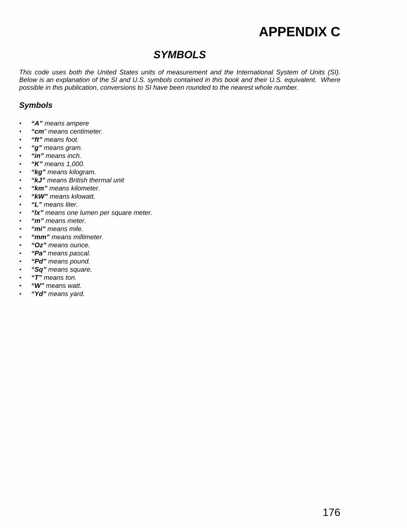
176
APPENDIX C
SYMBOLS
This code uses both the United States units of measurement and the International System of Units (SI).Below is an explanation of the SI and U.S. symbols contained in this book and their U.S. equivalent. Wherepossible in this publication, conversions to SI have been rounded to the nearest whole number.
Symbols
• “A” means ampere• “cm” means centimeter.• “ft” means foot.• “g” means gram.• “in” means inch.• “K” means 1,000.• “kg” means kilogram.• “kJ” means British thermal unit• “km” means kilometer.• “kW” means kilowatt.• “L” means liter.• “lx” means one lumen per square meter.• “m” means meter.• “mi” means mile.• “mm” means millimeter.• “Oz” means ounce.• “Pa” means pascal.• “Pd” means pound.• “Sq” means square.• “T” means ton.• “W” means watt.• “Yd” means yard.