Embed Size (px)
Citation preview

181
ORIGINAL PAPER
Nagoya J. Med. Sci. 75. 181 ~ 192, 2013
MECHANICAL ADVANTAGES OF A TRUSS-STRUCTURE-BASED FRACTURE FIXATION SYSTEM
– A NOVEL FRACTURE FIXATION DEVICE “PINFIX” –
TeTSuya arai, Michiro yaMaMoTo, KaTSuyuKi iwaTSuKi, Tadahiro NaTSuMe, TaKaaKi ShiNohara, MaSahiro TaTebe, Shigeru KuriMoTo,
hideyuKi oTa, Shuichi KaTo and hiToShi hiraTa
Department of Hand Surgery, Nagoya University Graduate School of Medicine, Nagoya, Japan
abSTracT
a small, light, ball-joint device called PinFix, which can instantly convert a simple percutaneous cross pin fracture fixation system into a rigid external fracture fixation system based on truss structure, was developed. The purpose of this study was to compare the mechanical load and breaking strength of this truss-structure-based fixation system to that of the conventionally used external cantilever structure-based fixation system. Three types of mechanical loading tests, axial, bending, and torsion, were performed on an artificial fractured bone treated with either three-dimensional PinFix fixation, two-dimensional PinFix fixation, or conventional external fixation. The three- and two-dimensional PinFix fixations showed signifi-cantly more stiffness than conventional fixation on all three loading tests. Finite element analysis was next performed to calculate the stress distribution of the parts in PinFix and in the conventional fixator. The applied stress to the rod and connectors of PinFix was much less than that of the conventional external fixator. These results reflected the physical characteristic of truss structure in which applied load is converted to pure tension or compression forces along the members of the PinFix. in conclusion, PinFix is a simple fracture fixation system that has a truss-structure with a high rigidity.
Key words: truss-structure, fracture fixation system, PinFix
iNTroducTioN
Providing sufficient stability, preservation of circulation, and avoidance of infection at the fracture site are the three most important requirements for promoting fracture healing.1-3) in order to provide an optimal healing environment, various fracture fixation techniques have been developed, such as transcutaneous Kirschner wire (K-wire) fixation, external fixation, plating, and intramedullary nailing.3-5) each method has its advantages and disadvantages. in terms of circulation preservation and infection avoidance, transcutaneous Kirschner wire (K-wire) fixation and external fixation have theoretical advantages over plating and intramedullary nailing due to their minimum damage to soft tissues and fracture fragments.6, 7) in addition, these procedures are usually performed following closed reduction. conversely, plating and intramedullary nailing tend
received: February 20, 2013; accepted: May 13, 2013
corresponding author: Tetsuya arai
department of hand Surgery, Nagoya university graduate School of Medicine,
65 Tsurumai-cho, Showa-ku, Nagoya 466-8550, Japan
Tel: +81-52-744-2957; Fax: +81-52-744-2964, e-mail: [email protected]
182
Tetsuya Arai et al.
to be more harmful to the fracture site, but they generally allow more precise reduction, provide better stability, and allow patients more freedom of daily activity during fracture healing.8-10)
Percutaneous K-wire fixation is a cost-effective procedure that does not require any special devices for implementation. it is also technically less demanding and is highly versatile in terms of its range of application.11) however, fixation provided by K-wires alone is less secure and carries significantly higher risk of loss of reduction than other techniques even when applied to fractures in the upper extremities.12) external fixation can generally provide much higher stability at the fracture site than K-wire fixation.13-15) connections between the external fixation device and its screws are located outside of the body. because of the much longer lever arms compared to those of internal fixation devices, a huge moment of force develops around them. Therefore, all of the components have to be rigidly fixed so that the fixator system can keep its shape. This makes the external fixator a heavy, cumbersome, and less versatile device. as a result, most external fixators are designed for a specific site or a specific type of fracture and are supplied with special jigs for assembly. external fixator devices use a cantilever structure, and they are only supported on one side with screws that project horizontally in space.16) These factors make the external fixation devices more expensive and more technically demanding compared to K-wire fixation.
in architecture, bridges are designed and constructed using cantilever methods. To ameliorate the moment around the connections and to make them more robust against cyclic drifts, the use of diagonal support frames and sway braces is highly recommended.17) The X-bracing system is one of the easiest methods to transfer lateral loads in buildings.18) cross-bracing systems, with or without friction dampers, are believed to be fundamental for the seismic response.19) Therefore, cantilevered bridges in architecture are seldom completed as true cantilevers but are instead completed as truss bridges.17) a truss is a structure comprising one or more triangular units constructed with straight members whose ends are connected at joints, referred to as nodes,20) and external forces act only at the nodes and result in forces on the members that are either tensile or compressive, resulting in exclusion of moment.21, 22)
we have developed a novel ball-joint device named the PinFix that instantly converts a simple crossed K-wire fixation system into a robust external fixation system by constructing a truss structure.
The purpose of this study was to compare the mechanical load and breaking strength of the fracture fixation of PinFix to those of the conventional cantilever external fixator using an artificial bone model and finite element analysis.
MaTeriaLS aNd MeThodS
Mechanical loading testsThe PinFix is a plastic ball-joint weighing 2.9 g that can connect pins (ø1.6–2.4 mm) with
rods (ø3 mm) at any desired angle to form a truss-structure-based fracture fixation system. as shown in Fig. 1(a-e), the pins are inserted in a crisscross fashion across the fracture site. This is a universal system that can be used to construct either two- or three-dimensional fixations in any configuration.
a 30 radius sawbone with a cancellous inner core and a foam cortical shell (26 cm long, 5.5-mm canal diameter; Model #1027, Pacific research Laboratories, inc., Vashon, wa, uSa) was prepared for axial and bending load testing. The proximal radial shaft of each specimen was potted with a metallic adapter, leaving approximately 10 cm of the radius exposed. For the axial and bending load testing, an oscillating saw was used to create a transverse osteotomy
183
TRUSS-STRUCTURE-BASED FRACTURE FIXATION
3 mm proximal to the styloid process. a 3-mm fracture gap was created by making a second transverse osteotomy 3 mm proximal to the initial cut, and this section of bone was removed to simulate the complete lack of cortical contact seen in severely comminuted, unstable, extra-articular, distal radius fractures. The fracture models were divided randomly into the following groups: three-dimensional PinFix fixation (group a, n=5, Fig. 2a), two-dimensional PinFix fixation (group b, n=5, Fig. 2b), and conventional external fixation (hoffman ii mini external Fixator Stryker, Mahwah, NJ; group c, n=5, Fig. 2c). in the PinFix groups, 2.4-mm Kirschner wires were used for fixation. in group c, 3-mm dedicated threaded pins were used for fixation.
The fracture models were placed on the loading platform of a universal testing machine (autograph ag-1, Shimazu, Kyoto, Japan). each specimen was loaded at a rate of 1 N/s to a maximum load of 3-mm displacement for both axial (Fig. 3a) and bending loads (Fig. 3b), with 2-mm/min cross head speed. To generate optimal loading, a three-dimensional plastic gripping adaptor was put on the distal end of the sawbone radius during axial loading and on the volar side of the distal fragment during bending loading. displacements of 1, 2, and 3 mm were compared in the three groups, and the load-displacement curve was plotted for each axial and bending load.
in the torsion loading, the machine had to grip both ends of the bones, but the radius bone could not be gripped firmly because of the shape. instead, the femur sawbones were used. Fifteen femurs (Model #1130, Pacific research Laboratories, inc. Vashon, wa, uSa) were prepared for torsion load testing. both sides of the femur were cut at 10 cm from the fracture site and fixed
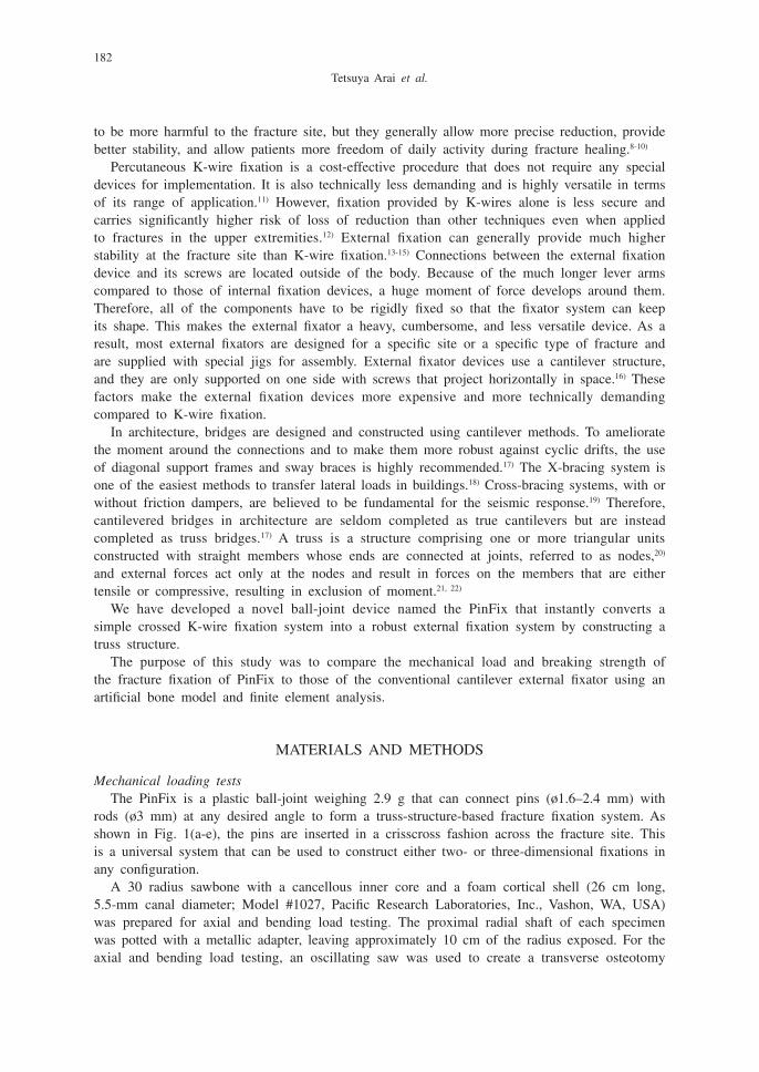
Fig. 1(a, b, c, d, e) Mechanism of the PinFix. The PinFix is a plastic ball-joint weighing 2.9 g that can connect pins (ø1.6–2.4 mm) with rods (ø3 mm) at any desired angle to form a truss-structure-based fracture fixation system. ‘a’ is the view from above. ‘b’ is the view from below. ‘c’ is the view from the side.
The pins are inserted across the fracture site in a crisscross fashion. This is a universal system that can construct either two- or three-dimensional fixations in any configuration. The assembly is infinite (d and e)
184
Tetsuya Arai et al.
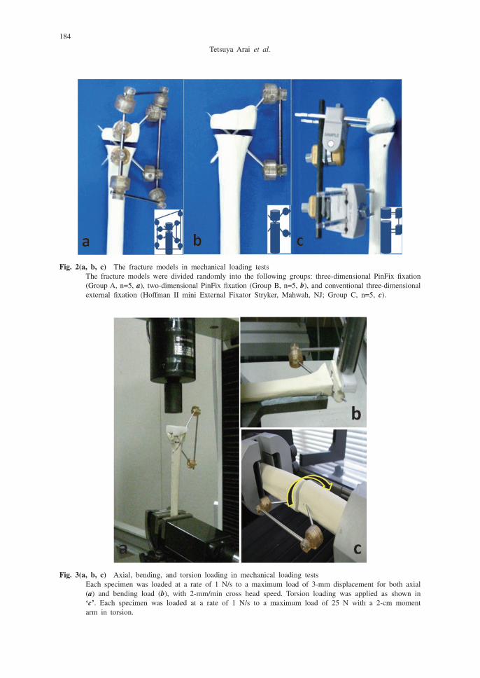
Fig. 3(a, b, c) axial, bending, and torsion loading in mechanical loading tests each specimen was loaded at a rate of 1 N/s to a maximum load of 3-mm displacement for both axial
(a) and bending load (b), with 2-mm/min cross head speed. Torsion loading was applied as shown in ‘c’. each specimen was loaded at a rate of 1 N/s to a maximum load of 25 N with a 2-cm moment arm in torsion.
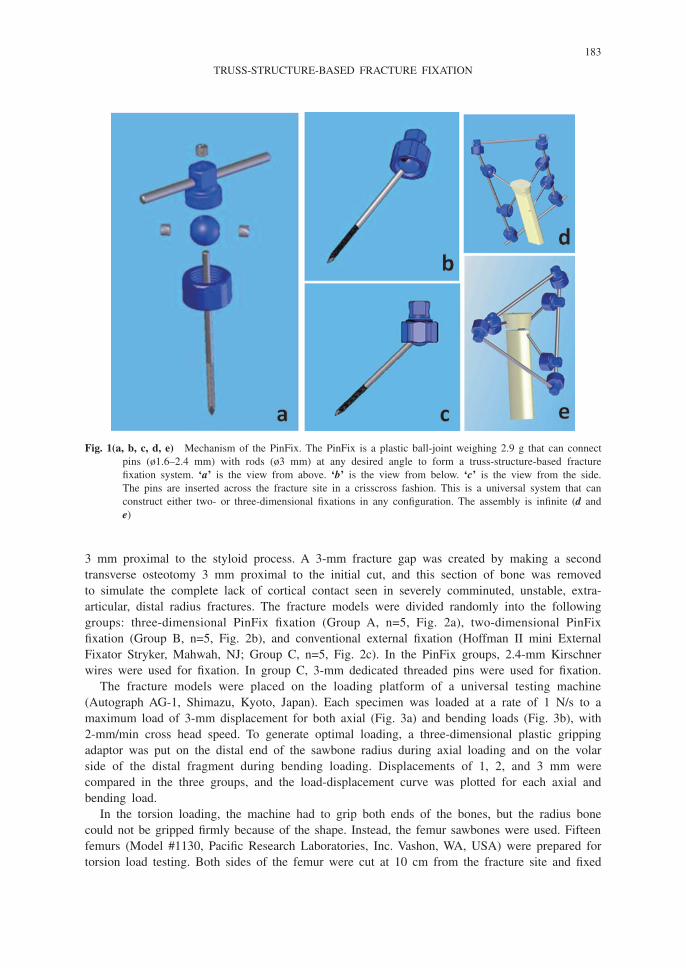
Fig. 2(a, b, c) The fracture models in mechanical loading tests The fracture models were divided randomly into the following groups: three-dimensional PinFix fixation
(group a, n=5, a), two-dimensional PinFix fixation (group b, n=5, b), and conventional three-dimensional external fixation (hoffman ii mini external Fixator Stryker, Mahwah, NJ; group c, n=5, c).
185
TRUSS-STRUCTURE-BASED FRACTURE FIXATION
using a metallic clamp of a testing machine (Low capacity Torsion Testing Systems, instron Japan, Kanagawa, Japan). The fracture fixation method using each fixator was tested in the same manner as the axial and bending loading. Torsion loading was applied as shown in Fig. 3c. each specimen was loaded at a rate of 1 N/s to a maximum load of 25 N with a 2-cm moment arm in torsion. rotations of 10 and 20 degrees were compared in the three groups, and the load-displacement curve was plotted.
Finite element analysisSimulated cylindrical bone that consisted of cancellous and cortical bone was created on the
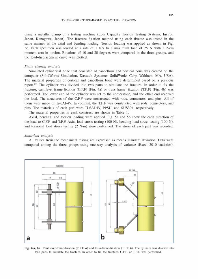
computer (Solidworks Simulation, dassault Systemes Solidworks corp. waltham, Ma, uSa). The material properties of cortical and cancellous bone were determined based on a previous report.23) The cylinder was divided into two parts to simulate the fracture. in order to fix the fracture, cantilever-frame-fixation (c.F.F) (Fig. 4a) or truss-frame- fixation (T.F.F) (Fig. 4b) was performed. The lower end of the cylinder was set to the cornerstone, and the other end received the load. The structures of the c.F.F were constructed with rods, connectors, and pins. all of them were made of Ti-6al-4V. in contrast, the T.F.F was constructed with rods, connectors, and pins. The materials of each part were Ti-6al-4V, PPSu, and SuS304, respectively.
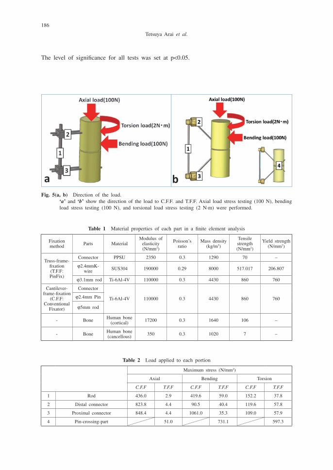
The material properties in each construct are shown in Table 1.axial, bending, and torsion loading were applied. Fig. 5a and 5b show the each direction of
the load to c.F.F and T.F.F. axial load stress testing (100 N), bending load stress testing (100 N), and torsional load stress testing (2 N∙m) were performed. The stress of each part was recorded.
Statistical analysisall values from the mechanical testing are expressed as means±standard deviation. data were
compared among the three groups using one-way analysis of variance (excel 2010 statistics).
Fig. 4(a, b) cantilever-frame-fixation (c.F.F. a) and truss-frame-fixation (T.F.F. b). The cylinder was divided into two parts to simulate the fracture. in order to fix the fracture, c.F.F. or T.F.F. was performed.
186
Tetsuya Arai et al.
The level of significance for all tests was set at p<0.05.
Table 1 Material properties of each part in a finite element analysis
Fixation method Parts Material
Modulus of elasticity (N/mm2)
Poisson’s ratio
Mass density (kg/m3)
Tensile strength (N/mm2)
yield strength (N/mm2)
Truss-frame-fixation (T.F.F: PinFix)
connector PPSu 2350 0.3 1290 70 –
φ2.4mmK-wire SuS304 190000 0.29 8000 517.017 206.807
φ3.1mm rod Ti-6al-4V 110000 0.3 4430 860 760
cantilever-frame-fixation
(c.F.F: conventional
Fixator)
connector
Ti-6al-4V 110000 0.3 4430 860 760φ2.4mm Pin
φ5mm rod
- bone human bone (cortical) 17200 0.3 1640 106 –
- bone human bone (cancellous) 350 0.3 1020 7 –
Table 2 Load applied to each portion
Maximum stress (N/mm2)
axial bending Torsion
C.F.F T.F.F C.F.F T.F.F C.F.F T.F.F
1 rod 436.0 2.9 419.6 59.0 152.2 37.8
2 distal connector 823.8 4.4 90.5 40.4 119.6 57.8
3 Proximal connector 848.4 4.4 1061.0 35.3 109.0 57.9
4 Pin-crossing-part 51.0 731.1 597.3
Fig. 5(a, b) direction of the load. ‘a’ and ‘b’ show the direction of the load to c.F.F. and T.F.F. axial load stress testing (100 N), bending
load stress testing (100 N), and torsional load stress testing (2 N∙m) were performed.

187
TRUSS-STRUCTURE-BASED FRACTURE FIXATION
reSuLTS
Mechanical loading testsAxial loading:
The load-displacement curve of the axial load is shown in Fig. 6. The load of 1-mm displacement for each group (a, b, c) with axial loading was 102.3±24.1 N, 56.2±18.2 N, and 14.9±3.7 N, respectively. That of 2-mm displacement was 209.4±37.2 N, 120.5±16.5 N, and 30.3±3.9 N, respectively, and 3-mm displacement was 310.9±48.8 N, 181.3±41.0 N, and 44.8±5.6 N, respectively.
comparisons between group a and c, and between group b and c, at 1-mm, at 2-mm, and at 3-mm displacements showed significant differences, with p-values of p=0.0001 and p=0.0134 at 1 mm, p=0.0001 and p=0.0111 at 2 mm, and p=0.0001 and p=0.0093 at 3 mm, respectively.
Bending loadingThe load-displacement curve of the bending load is shown in Fig. 7. The load of 1-mm
displacement for each group (a, b, c) in the bending loading was 21.8±13.9 N, 17.3±5.4 N, and 12.3±0.5 N, respectively. That of 2-mm displacement was 55.1±22.2 N, 43.8±9.2 N, and 23.7±2.2 N, respectively, and 3-mm displacement was 98.9±17.8 N, 68.5±13.0 N, and 32.0±3.1 N, respectively.
comparisons between group a and c and between group b and c at 1-mm and 2-mm displacements did not show significant differences (p=0.2022, p=0.4667, respectively). in con-trast, significant differences were found at 3-mm displacement, with p-values of p=0.0001 and p=0.0061, respectively.
Torsion loading:
Fig. 6 The load-displacement curves of the axial load. The meaning of each line is as follows: group a (dotted line), group b (continuous line), and group c (long dashed dotted line). comparisons of two different fixations for group a and group c and for group b and group c, demonstrate significant differences at 1-mm displacement (p=0.0001, p=0.0134, respectively), at 2-mm displacement (p=0.0001, p=0.0111), and at 3-mm displacement (p=0.0001, p=0.0093).

188
Tetsuya Arai et al.
Fig. 7 The load-displacement curves of the bending load. comparisons of two different fixations for group a and group c and for group b and group c, show
no significant differences at 1-mm displacement (p=0.2022, p=0.4667, respectively). although there are no significant differences between PinFix and conventional fixators at 1-mm and
2-mm displacements, a significant difference is seen at 3-mm displacement between group a and group c (p=0.0001) and between group b and group c (p=0.0061).
Fig. 8 The load-angle curves of the torsion load. comparisons of two different fixations for group a and group c and for group b and group c,
demonstrate significant differences at 10 degrees rotation (p=0.0000, p=0.0012), at 20 degrees rotation (p=0.0001, p=0.0111), and at 3-mm displacement (p=0.0000, p=0.0013). The three-dimensional PinFix fixation is strongest in torsion loading.

189
TRUSS-STRUCTURE-BASED FRACTURE FIXATION
The load-angle curve of torsion loading is shown in Fig. 8. The torque of 10-degree rotation for each group (a, b, c) in the torsion loading was 37.2±4.0 N∙m, 22.5±1.7 N∙m, and 16.4±1.4 N∙m, respectively. That of 20-degree rotation was 58.6±4.8 N∙m, 33.0±1.1 N∙m, and 24.7±2.7 N∙m, respectively.
comparisons between group a and c and between group b and at 10-degree and 20-degree rotations demonstrated significant differences, with p-values of p<0.0000 and p=0.0012 at 10 degrees, and p=0.0001 and p=0.0111 at 20 degrees, respectively. The three-dimensional PinFix fixation was the strongest in torsion loading.
Finite element analysisas can be seen in Tables 1 and 2, finite element analysis (Fea) showed remarkable differences
in the stress distribution pattern between c.F.F and T.F.F. under all three loading conditions. in axial loading, stress in the rod was 436.0 N/mm2 in c.F.F, while that in T.F.F, was 2.9 N/mm2, and stress at the distal and proximal connectors of c.F.F was 823.8 N/mm2 and 848.4 N/mm2, while stress at the distal and proximal connectors of T.F.F. were 4.4 N/mm2 and 4.4 N/mm2, respectively. in bending loading, stress on the rod was 419.6 N/mm2 in c.F.F, while that in T.F.F was 59.0 N/mm2, and stress at the distal and proximal connectors of c.F.F was 90.5 N/mm2 and 1061.0 N/mm2, respectively, while stress at the distal and proximal connectors of T.F.F. was 40.4 N/mm2 and 35.3 N/mm2, respectively. in torsion loading, stress on the rod was 152.2 N/mm2 in c.F.F, while that in T.F.F was 37.8 N/mm2, and stress at the distal and proximal connectors of c.F.F was 119.6 N/mm2 and 109.0 N/mm2, respectively, while stress at the distal and proximal connecters of c.F.F was 57.8 N/mm2 and 57.9 N/mm2, respectively.
The results clearly demonstrated the differences between c.F.F. and T.F.F. under all three loading conditions. on the other hand, in T.F.F., a relatively high stress concentration takes place along the crossing pins inside the bone, with values of 51.0 N/mm2 in axial loading, 731.1 N/mm2 in bending loading, and 597.3 N/mm2 in torsion loading. it appears that higher stress concentrations occur in rods and connectors in c.F.F, while the same happens in crossing pins inside the bone in T.F.F. These results indicate that the applied load is converted to a pure compression or tension load along the pins in the PinFix, thereby significantly reducing stress in members outside the bones.
diScuSSioN
Truss-frames are composed of triangles that are the simplest geometric figure that will not deform once the lengths of the sides are fixed. in comparison, a four-sided figure such as a cantilever-frame will change shape in response to external forces. Therefore, both the angles and the lengths must be firmly fixed to retain its shape.
Finite element analysis clearly showed high stress concentrations at the angles of the cantilever frame. in contrast, in the case of a truss frame, the mechanical stress is spread along the pins crossing the fracture site, and, therefore, less stress concentration occurs at the joints or along the rods. Therefore, the structure can be constructed using relatively small and weak connecting materials. because of this, it was possible to make the PinFix with plastic parts as light as 3 g each. despite the lightweight material used, all mechanical load testing clearly demonstrated that the PinFix truss fixation can better withstand mechanical stresses in all directions than can conventional external fixator systems.
in truss structure, it is noteworthy that the predicted axial force is significantly smaller than the bending or torsion force. This result could be explained by the law of the lever.24) in the
190
Tetsuya Arai et al.
case of axial load analysis, the axis of the applied load is almost collinear with the longitudinal axis of the bone. Therefore, the lever arm is practically zero. in contrast, in the case of bending and torsional load testing, the axis of the load is distant from the action point. a much larger lever arm in these tests results in much higher mechanical stress at the action point.
on the other hand, Fea showed a relatively high stress concentration along the pins around the cross part despite the fact that the two pins are not connected to each other within the bone in the PinFix. This reflects the physical characteristics of the truss, in which the applied deforming force is converted into pure compression or tension stress along the parts. This type of structure is widely used in a variety of truss constructions, such as brown truss bridges.25, 26)
The mechanical loading test clearly showed the greater stiffness of the truss-frame, both of the three- and two-dimensional PinFix, than that of the cantilever-frame. in addition, the three-dimensional PinFix was obviously stiffer than the two-dimensional PinFix. This indicates that a more robust structure can be constructed by combining the simple truss structures. in fact, according to Pouangare,27) a complex three-dimensional truss, alias ‘the space-truss’, can give constructions with extremely high strength.
in our mechanical study, sawbones were used. The main advantage28) of using sawbones is that their use has been well validated in comparisons with cadaver specimens, and they are considerably better represented in hand and upper extremity biomechanics research. in fact, a variety of problems with cadaver specimens have been pointed out, including high cost, tenuous availability, handling and storage challenges, and a remarkable degree of inter-specimen variability that reportedly exceeds 100% of the mean in some metrics.
historically, crisscross pin fixation has been widely used in fracture management.13) it is a less invasive fracture fixation technique that can be performed at any medical facility that uses simple fracture treatment devices such as image intensifiers, drills, and Kirschner wires. in addition, the technique is also widely used during surgery to temporarily maintain reduction until internal fixation with plates is completed. The caveat is that it is much less reliable compared to other fracture techniques and almost always requires additional supports such as cast immobilization.29) however, once the PinFix is attached to the Kirschner wires, it instantaneously becomes a stronger supporting device compared to other fixation systems.
PinFix is not the only external fixator using the truss structure. The cPX system developed by Mirza et al. is a uniplane external fixation system that supports multiple, small, 1.6-mm cross-pins.30) using a cadaveric fracture model, Strauss et al. compared the cPX system with volar locking plate fixation and concluded that there was no significant difference between the two fixation techniques. Their results also proved the mechanical advantages of a truss system. The problem of cPX is that it is a site-specific fracture fixation system. it can only be applied to a limited number of fracture types of the distal radius, such as ao type b2 or b3.31) in contrast, the PinFix can be used in various types and at various sites of fracture without requiring any special devices. indeed, a distal radius fracture might be a good indication for the PinFix, and it can also be used for forearm, elbow, and humerus fractures.
This study clearly demonstrated the usefulness of introducing the basics of structural engineer-ing to the designing of fracture fixation devices.
in conclusion, by taking the mechanical advantages of truss structures into consideration, a simple fracture fixation device, the PinFix, which can convert a simple cross pin fixation into an extremely robust external fixation system by inducing drastic changes in load distribution, was successfully developed.
191
TRUSS-STRUCTURE-BASED FRACTURE FIXATION
acKNowLedgeMeNTS
None of the authors of this manuscript has received any type of support, benefits, or funding from any commercial party related directly or indirectly to the subject of this article.
reFereNceS
1) worlock P, Slack r, harvey L. The prevention of infection in open fractures: an experimental study of the effect of fracture stability. Injury 1994; 25: 31–38.
2) Miclau T, Martin re. The evolution of modern plate osteosynthesis. Injury 1997; 28: S-a3-S-a6. 3) reynders Pa, broos PLo. healing of closed femoral shaft fractures treated with the ao unreamed femoral
nail. a comparative study with the ao reamed femoral nail. Injury 2000; 31: 367–371. 4) calder Pr, achan P, barry M. diaphyseal forearm fractures in children treated with intramedullary fixation:
outcome of K-wire versus elastic stable intramedullary nail. Injury 2003; 34: 278–282. 5) brooks Kr, capo JT, warburton M. internal fixation of distal radius fractures with novel intramedullary
implants. Clinical Orthopaedics Related Research 2006; 445: 42–50. 6) hamid r. Mostafavi cS. crossed Pin Fixation of displaced Supracondylar humerus Fractures in children.
Clinical Orthopaedics Related Research 2000; 376: 56–61. 7) Tu yK, Lin ch, Su Ji. unreamed interlocking Nail versus external Fixator for open Type iii Tibia
Fractures. The Journal of Trauma 1995; 39: 361–367. 8) Michael S. revolution in plate osteosynthesis: new internal fixator systems. J Orthop Sci 2003; 8: 252–258. 9) Koval KJ, harrast JJ, anglen Jo. Fractures of the distal part of the radius. The evolution of practice over
time. where’s the evidence? J Bone Joint Surg American Volume 2008; 90: 1855–1861.10) chung Kc, Shauver MJ, birkmeyer Jd. Trends in the united States in the treatment of distal radial fractures
in the elderly. J Bone Joint Surg American Volume 2009; 91: 1868–1873.11) Faraj a. Percutaneous intramedullary fixation of metacarpal shaft fractures. J Hand Surg 1999; 24: 76–79.12) Shalom S. complications of K-wire fixation of fractures and dislocations in the hand and wrist. Arch Orthop
Trauma Surg 2001; 121: 527–530.13) handoll hhg, Vaghela MV, Madhok r. Percutaneous pinning for treating distal radial fractures in adults
(review). Cochrane Review 2008: 1–70.14) handoll hhg, huntley JS, Madhok r. external fixation versus conservative treatment for distal radial
fractures in adults (review). Cochrane Review 2008: 1–78.15) Margic K. external fixation of closed metacarpal and phalangeal fractures of digits. a prospective study
of one hundred consecutive patients. J Hand Surg 2006; 31: 30–40.16) wolfe Sw, austin g, Lorenze M. a biomechanical comparison of different wrist external Fixators with
and without K-wire augmentation. J Hand Surg 1999; 24a: 516–524.17) Shama aa, Mander Jb, chen SS. ambient vibration and seismic evaluation of a cantilever truss bridge.
Engineering Structures 2001; 23: 1281–1292.18) wakabayashi M. design of earthquake-resistant buildings. The Mcgraw-hill companies, inc 1986.19) colajanni P. Seismic response of braced frames with and without friction dampers. Engng Struct 1993; 17:
129–140.20) deb K, gulati S. design of truss-structures for minimum weight using genetic algorithms. Finite Elements
in Analysis and Design 2001; 37: 447–465.21) gil L, andreu a. Shape and cross-section optimisation of a truss structure. Computers & Structures. 2001;
79(7): 681–689. 22) Pedersen NL, Nielsen aK. optimization of practical trusses with constraints on eigenfrequencies, displace-
ments, stresses, and buckling. Structural and Multidisciplinary Optimization 2003; 25: 436–445.23) okazaki y, goto e, doi K. Mechanical Simulation of compression hip Screw (chS) and hip Screw Nail
(hSN). Clinical Biomechanics 2009; 30: 229–232 (in Japanese).24) westneat Mw. a biomechanical model for analysis of muscle force, power output and lower jaw motion
in fishes. J Theoretical Biology 2003; 223: 269–281.25) brown J. Truss bridge. united States Patent office 1857; Specification of letters Patent No17722.26) dylan M, Lamar bwS. Structural analyses of Two historic covered wooden bridges. Journal of Bridge
Engineering 2004; 9: 623–633.27) Pouangare cc. New structural systems for tall buildings: the space-truss concept. The Structural Design of
192
Tetsuya Arai et al.
Tall Buildings 1995; 4: 155–168.28) reed Jd, Stanbury SJ, Menorca rM, elfar Jc. The emerging utility of composite bone models in biome-
chanical studies of the hand and upper extremity. J Hand Surg 2013; 38: 583–587.29) van aaken J, beaulieu Jy, Fusetti c. Long-term outcomes of closed reduction and percutaneous pinning
for the treatment of distal radius fractures. J Hand Surg 2009; 34: 963; author reply 963–964.30) Mirza a, reinhart MK, bove JJ. Treatment of distal radius Fractures with a Nonbridging cross-Pin Fixator
(The cPX System). Techniques in Hand & Upper Extremity Surgery 2009; 13: 104–109.31) Strauss eJ, banerjee d, Kummer FJ. evaluation of a novel, nonspanning external fixator for treatment of
unstable extra-articular fractures of the distal radius: biomechanical comparison with a volar locking plate. J Trauma 2008; 64: 975–981.