Embed Size (px)
Citation preview
当社の圧力センサは「流体の圧力」を「電気信号」に変
換する圧力変換器です。
半導体技術を駆使し、センサ素子から各種応用製品ま
で一貫して自社生産を行っています。おもな特長は次の
とおりです。
1.小型、軽量
2.すぐれた電気的、機械的特性
3.使用目的に適合した幅広い製品群
A pressure sensor is a device that converts fluid pressure in to an e lect r ica l s ignal . COPAL ELECTRONICS pressure sensors are man u fac-tured from the semiconductor pressure sensing chips to a variety of pressure sensor products at its own facility.
COPAL ELECTRONICS pressure sensors feature:1. Compact and light weight2 . Exce l l en t e l ec t r i ca l and mechan i ca l
performance3. Wide range of products to choose from for
various applications
a)拡散形半導体圧力トランスジューサ…
Pシリーズ
圧力を電気信号に変換する基本的な素子。定電流を印
加すると圧力に比例した電圧を出力します。正圧の場合
はプラス、負荷の場合はマイナスの電圧が出力されます。
■製品ラインアップ ■ PRODUCT LINE-UPa) Diffusion type semi-conductor pressure sensors ···
P seriesA basic pressure sensing device which converts pressure into an electrical signal.The output is in the form of vo l tage which is proportional to the applied pressure.The output voltage will be positive when the pressure is positive and negative when the pressure is negative with a constant current source connected.
b)アンプ内蔵型圧力トランスジューサ…
PAシリーズ
拡散形半導体圧力トランスジューサと電子回路を組合せ、
圧力をアナログ電気信号として出力する圧力センサです。
電子回路は、圧力トランスジューサに必要な駆動電流を作
り出す 電圧・電流変換部 及び圧力トランスジューサの出
力を増幅し、規定された出力に調整する増幅部で、構成さ
れます。
信号出力は、圧力変化に比例した電気信号であり、電圧
変化(電圧出力型)若しくは、電流変化(電流出力型)と
なります。
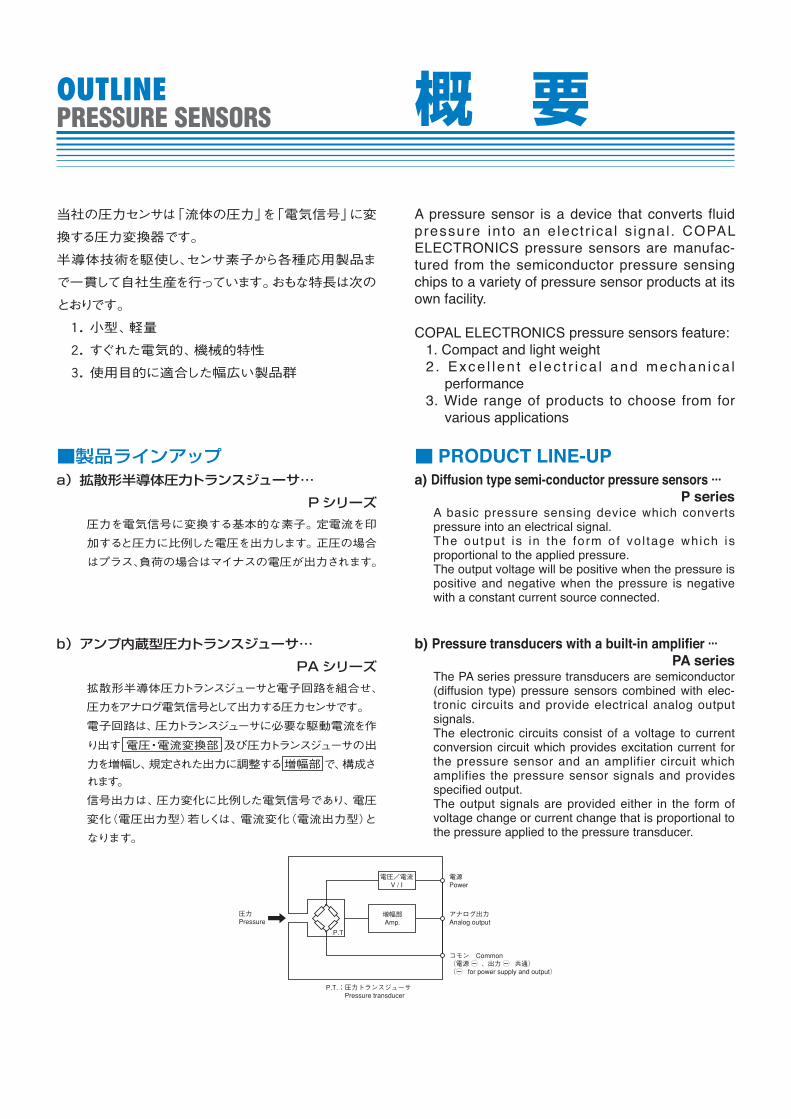
b) Pressure transducers with a built-in amplifier ···PA series
The PA series pressure transducers are semiconductor (diffusion type) pressure sensors combined with elec-tronic circuits and provide electrical analog output signals.The electronic circuits consist of a voltage to current conversion circuit which provides excitation current for the pressure sensor and an amplifier circuit which amplifies the pressure sensor signals and provides specified output.The output signals are provided either in the form of voltage change or current change that is proportional to the pressure applied to the pressure transducer.
圧力Pressure
増幅部Amp.
電源Power
アナログ出力Analog output
コモン Common(電源 C 、出力 C 共通)(C for power supply and output)
P.T.:圧力トランスジューサ Pressure transducer
電圧/電流V / I
P.T
OUTLINEPRESSURE SENSORS 概 要
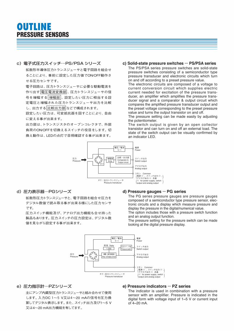
c) Solid-state pressure switches ··· PS/PSA seriesThe PS/PSA series pressure switches are solid-state pressure switches consisting of a semiconductor type pressure transducer and electronic circuits which turn on and off accord ing to a preset pressure value.The electronic circuits are composed of a voltage to current conversion circuit which supplies electric current needed for excitation of the pressure trans-ducer, an amplifier which amplifies the pressure trans-ducer signal and a comparator & output circuit which compares the amplified pressure transducer output and the preset voltage corresponding to the preset pressure value and turns the output transistor on and off.The pressure setting can be made easily by adjusting the potentiometer.The switch output is given by an open collector transistor and can turn on and off an external load. The state of the switch output can be visually confirmed by an indicator LED.
c)電子式圧力スイッチ…PS/PSAシリーズ
拡散形半導体圧力トランスジューサと電子回路を組合せ
ることにより、事前に設定した圧力値でON/OFF動作さ
せる圧力センサです。
電子回路は、圧力トランスジューサに必要な駆動電流を
作り出す電圧電流変換部、圧力トランスジューサの信
号を増幅する 増幅部 、設定したい圧力に相当する設
定電圧と増幅された圧力トランスジューサ出力を比較
し、出力する比較出力部などで構成されます。
設定したい圧力は、可変抵抗器を回すことにより、自由
に変える事が出来ます。
出力部は、トランスジスタのオープンコレクタで、外部
負荷のON/OFFを切換えるスイッチの役目をします。切
換え動作は、LEDの点灯で目視確認する事が出来ます。
e)圧力指示計…PZシリーズ
主にアンプ内蔵型圧力トランスジューサと組み合わせて使用
します。入力DC1~5 V又は4~20 mAの信号を圧力換
算してデジタル表示します。また、スイッチ出力及び1~5 V
又は4~20 mA出力機能を有してます。
e) Pressure indicators ··· PZ seriesThe indicator is used in combination with a pressure sen sor with an amplifier. Pressure is indicated in the dig i tal form with voltage input of 1~5 V or current input of 4~20 mA.
d)圧力表示器…PGシリーズ
拡散形圧力トランスジューサと、電子回路を組合せ圧力を
デジタル数値で読み取る事が出来る様にした圧力センサ
です。
圧力スイッチ機能及び、アナログ出力機能も合せ持った
製品もあります。圧力スイッチの圧力設定は、デジタル数
値を見ながら設定する事が出来ます。
d) Pressure gauges ··· PG seriesThe PG series pressure gauges are pressure gauges composed of a semiconductor type pressure sensor, elec-tronic circuits and a display which measure pres sure and display the pressure in the digital/numerical value.The option includes those with a pressure switch function and an analog output function.The pressure setting for the pressure switch can be made looking at the digital pressure display.
圧力Pressure
増幅部Amp.
比較・出力部Comparator & Output circuit
電源Power
スイッチ出力Switch output
アナログ出力Analog output
コモン Common 電源 C 、スイッチ出力 C 、 アナログ出力 C 共通 C for power supply, switch output and analog output
P.T.:圧力トランスジューサ Pressure transducer
電圧/電流V / I
P.T
((
))
圧力Pressure
増幅・表示回路部Amp. & Display circuit
1.000
表示部 Display圧力スイッチ部Pressure switch
電源Power
スイッチ出力Switch output
アナログ出力Analog output
P.T:圧力トランスジューサ Pressure transducer
電圧/電流V / I
P.T
コモン Common 電源 C 、スイッチ出力 C 、 アナログ出力 C 共通 C for power supply, switch output and analog output
((
))
OUTLINEPRESSURE SENSORS
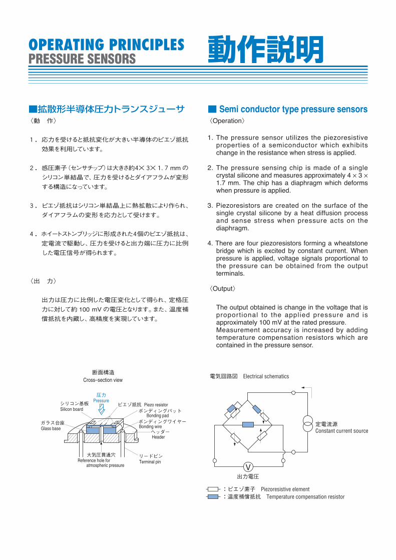
■拡散形半導体圧力トランスジューサ〈動 作〉
1.応力を受けると抵抗変化が大きい半導体のピエゾ抵抗
効果を利用しています。
2.感圧素子(センサチップ)は大きさ約4×3×1.7 mmの
シリコン単結晶で、圧力を受けるとダイアフラムが変形
する構造になっています。
3.ピエゾ抵抗はシリコン単結晶上に熱拡散により作られ、
ダイアフラムの変形を応力として受けます。
4.ホイートストンブリッジに形成された4個のピエゾ抵抗は、
定電流で駆動し、圧力を受けると出力端に圧力に比例
した電圧信号が得られます。
〈出 力〉
出力は圧力に比例した電圧変化として得られ、定格圧
力に対して約100 mVの電圧となります。また、温度補
償抵抗を内蔵し、高精度を実現しています。
■ Semi conductor type pressure sensors〈Operation〉
1. The pressure sensor utilizes the piezoresistive properties of a semiconductor which exhibits change in the resistance when stress is applied.
2. The pressure sensing chip is made of a single crystal silicone and measures approximately 4 × 3 × 1.7 mm. The chip has a diaphragm which deforms when pressure is applied.
3. Piezoresistors are created on the surface of the single crystal silicone by a heat diffusion process and sense stress when pressure acts on the diaphragm.
4. There are four piezoresistors forming a wheatstone bridge which is excited by constant current. When pressure is applied, voltage signals proportional to the pressure can be obtained from the output terminals.
〈Output〉
The output obtained is change in the voltage that is proport ional to the appl ied pressure and is approximately 100 mV at the rated pressure.Measurement accuracy is increased by adding temperature compensation resistors which are contained in the pressure sensor.
大気圧貫通穴Reference hole for atmospheric pressure
ガラス台座Glass base
シリコン基板Silicon board
圧力Pressure
ピエゾ抵抗ボンディングパット
ボンディングワイヤー
ヘッダー
Piezo resistor
Bonding pad
Bonding wire
Header
リードピンTerminal pin
断面構造Cross–section view
:ピエゾ素子 Piezoresistive element
電気回路図 Electrical schematics
:温度補償抵抗 Temperature compensation resistor
定電流源Constant current source
出力電圧V
OPERATING PRINCIPLESPRESSURE SENSORS 動作説明
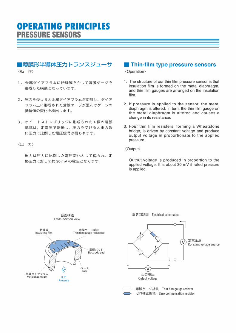
■薄膜形半導体圧力トランスジューサ〈動 作〉
1.金属ダイアフラムに絶縁膜を介して薄膜ゲージを
形成した構造となっています。
2.圧力を受けると金属ダイアフラムが変形し、ダイア
フラム上に形成された薄膜ゲージが歪んでゲージの
抵抗値の変化を検出します。
3.ホイートストンブリッジに形成された4個の薄膜
抵抗は、定電圧で駆動し、圧力を受けると出力端
に圧力に比例した電圧信号が得られます。
〈出 力〉
出力は圧力に比例した電圧変化として得られ、定
格圧力に対して約 30 mV の電圧となります。
■ Thin-film type pressure sensors〈Operation〉
1. The structure of our thin film pressure sensor is that insulation film is formed on the metal diaphragm, and thin film gauges are arranged on the insulation film.
2. If pressure is applied to the sensor, the metal diaphragm is altered. In turn, the thin film gauge on the metal diaphragm is altered and causes a change in its resistance.
3. Four thin film resisters, forming a Wheatstone bridge, is driven by constant voltage and produce output voltage in proportionate to the applied pressure.
〈Output〉
Output voltage is produced in proportion to the applied voltage. It is about 30 mV if rated pressure is applied.
OPERATING PRINCIPLESPRESSURE SENSORS
:薄膜ゲージ抵抗 Thin film gauge resistor
電気回路図 Electrical schematics
:ゼロ補正抵抗 Zero compensation resistor
定電圧源Constant voltage source
Output voltage出力電圧
V
V
圧力Pressure
電極パッドElectrode pad
薄膜ゲージ抵抗Thin �lm gauge resistance
絶縁膜Insulating �lm
ベースBase
金属ダイアフラムMetal diaphragm
断面構造Cross–section view
PA-838-D
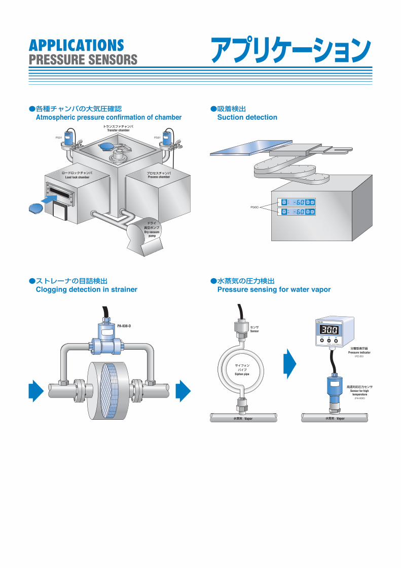
●ストレーナの目詰検出Clogging detection in strainer
Transfer chamber
Load lock chamber Process chamber
Dry vacuum pump
●各種チャンバの大気圧確認Atmospheric pressure confirmation of chamber
Sensor
Pressure indicator
Sensor for high temperature
Siphon pipe
Vapor Vapor
●水蒸気の圧力検出Pressure sensing for water vapor
●吸着検出Suction detection
APPLICATIONSPRESSURE SENSORS アプリケーション
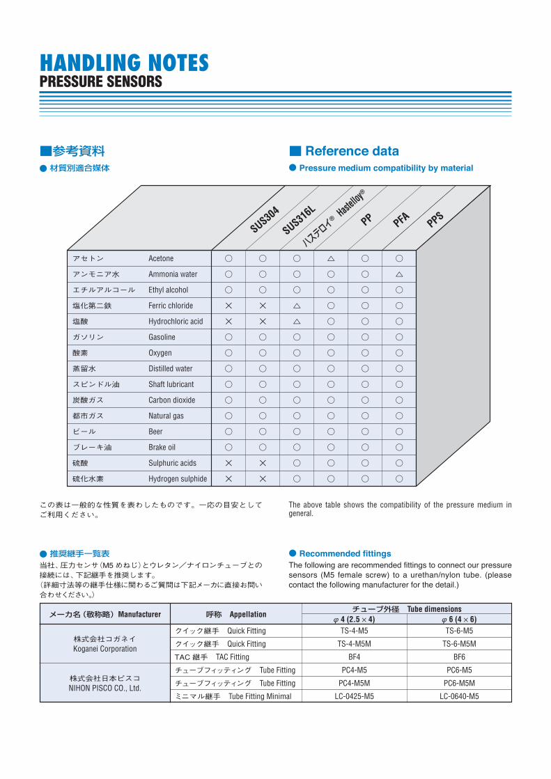
WorkForeign particle
Vacuum pump
Milling blade
APPLICATIONSPRESSURE SENSORS
●フライスなどのワークの着座不良検出Detection of foreign particle by fraise
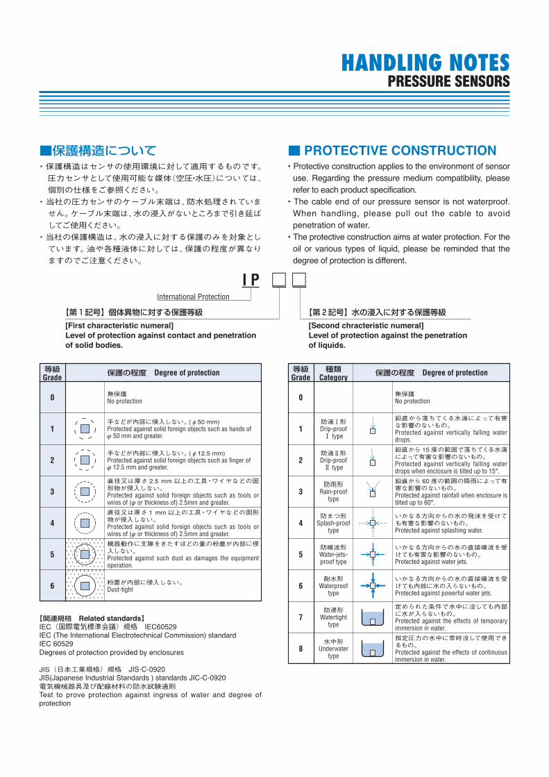
●河川の水位計測Measuring of water level
Vacuum pump
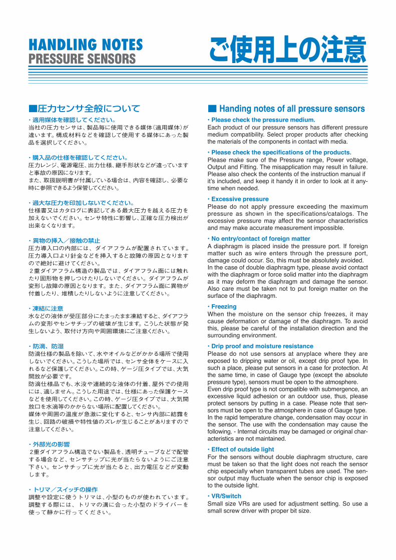
samples
Table for samples
●血液分析装置での吸引圧検出Detection of vacuum level for blood analyzing apparatus
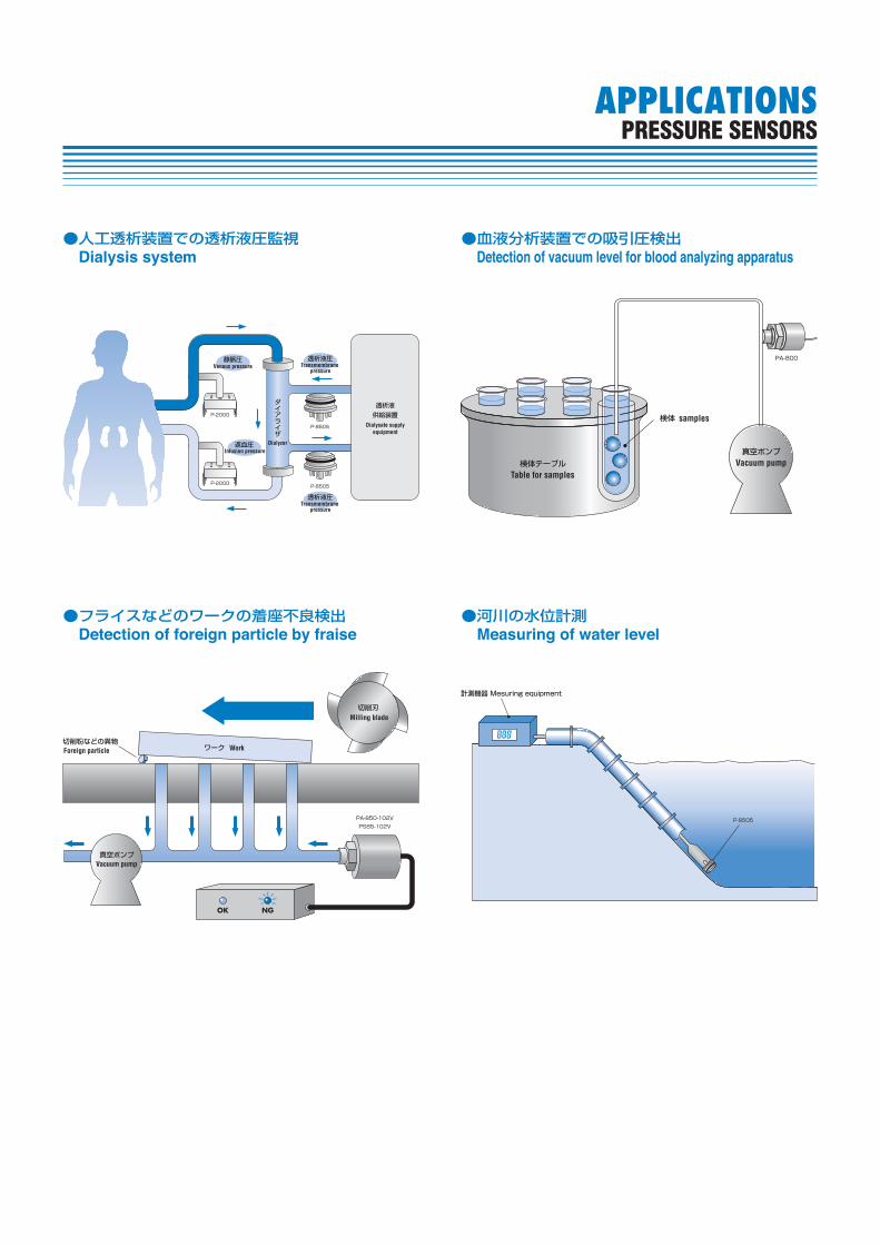
Venous pressure
Infusion pressureDialyzer
Transmembrane pressure
Transmembrane pressure
Dialysate supplyequipment
●人工透析装置での透析液圧監視Dialysis system
・適用媒体を確認してください。当社の圧力センサは、製品毎に使用できる媒体(適用媒体)が違います。構成材料などを確認して使用する媒体にあった製品を選択してください。
・購入品の仕様を確認してください。圧力レンジ、電源電圧、出力仕様、継手形状などが違っていますと事故の原因になります。また、取扱説明書が付属している場合は、内容を確認し、必要な時に参照できるよう保管してください。
・過大な圧力を印加しないでください。仕様書又はカタログに表記してある最大圧力を越える圧力を加えないでください。センサ特性に影響し、正確な圧力検出が出来なくなります。
・異物の挿入/接触の禁止圧力導入口の内部には、ダイアフラムが配置されています。圧力導入口より針金などを挿入すると故障の原因となりますので絶対に避けてください。2重ダイアフラム構造の製品では、ダイアフラム面には触れたり固形物を押しつけたりしないでください。ダイアフラムが変形し故障の原因となります。また、ダイアフラム面に異物が付着したり、堆積したりしないように注意してください。
・凍結に注意水などの液体が受圧部分にたまったまま凍結すると、ダイアフラムの変形やセンサチップの破壊が生じます。こうした状態が発生しないよう、取付け方向や周囲環境にご注意ください。
・防滴、防湿防滴仕様の製品を除いて、水やオイルなどがかかる場所で使用しないでください。こうした場所では、センサ全体をケースに入れるなど保護してください。この時、ゲージ圧タイプでは、大気開放が必要です。防滴仕様品でも、水没や連続的な液体の付着、屋外での使用には、適しません。こうした用途では、仕様にあった保護ケースなどを使用してください。この時、ゲージ圧タイプでは、大気開放口を水滴等のかからない場所に配置してください。媒体や周囲の温度が急激に変化すると、センサ内部に結露を生じ、回路の破損や特性値のズレが生じることがありますので注意してください。
・外部光の影響2重ダイアフラム構造でない製品を、透明チューブなどで配管する場合など、センサチップに光が当たらないようにご注意下さい。センサチップに光が当たると、出力電圧などが変動します。
・トリマ/スイッチの操作調整や設定に使うトリマは、小型のものが使われています。調整する際には、トリマの溝に合った小型のドライバーを使って静かに行ってください。
Each product of our pressure sensors has different pres sure medium compatibility. Select proper products after check ing the materials of the components in contact with media.
Please make sure of the Pressure range, Power voltage, Output and Fitting. The misapplication may result in failure. Please also check the contents of the instruction manu al if
time when needed.
Please do not apply pressure exceeding the maximum pres sure as shown in the specifications/catalogs. The exces sive pressure may affect the sensor characteristics and may make accurate measurement impossible.
A diaphragm is placed inside the pressure port. If foreign matter such as wire enters through the pressure port, damage could occur. So, this must be absolutely avoided.In the case of double diaphragm type, please avoid contact with the diaphragm or force solid matter into the diaphragm as it may deform the diaphragm and damage the sensor. Also care must be taken not to put foreign matter on the surface of the diaphragm.
When the moisture on the sensor chip freezes, it may cause deformation or damage of the diaphragm. To avoid this, please be careful of the installation direction and the surrounding environment.
Please do not use sensors at anyplace where they are exposed to dripping water or oil, except drip proof type. In such a place, please put sensors in a case for protection. At the same time, in case of Gauge type (except the absolute pressure type), sensors must be open to the atmosphere.Even drip proof type is not compatible with submergence, an excessive liquid adhesion or an outdoor use, thus, please protect sensors by putting in a case. Please note that sen-sors must be open to the atmosphere in case of Gauge type.In the rapid temperature change, condensation may occur in the sensor. The use with the condensation may cause the fol low ing. - Internal circuits may be damaged or original char-ac ter istics are not maintained.
For the sensors without double diaphragm structure, care must be taken so that the light does not reach the sensor chip especially when transparent tubes are used. The sen-sor output may fluctuate when the sensor chip is exposed to the outside light.
Small size VRs are used for adjustment setting. So use a small screw driver with proper bit size.
■圧力センサ全般について ■ Handing notes of all pressure sensors
HANDLING NOTESPRESSURE SENSORS ご使用上の注意
HANDLING NOTESPRESSURE SENSORS
■参考資料 ■ Reference data材質別適合媒体 Pressure medium compatibility by material
推奨継手一覧表 Recommended fittings
この表は一般的な性質を表わしたものです。一応の目安としてご利用ください。
The above table shows the compatibility of the pressure medium in general.
当社、圧力センサ(M5めねじ)とウレタン/ナイロンチューブとの接続には、下記継手を推奨します。(詳細寸法等の継手仕様に関わるご質問は下記メーカに直接お問い合わせください。)
The following are recommended fittings to connect our pres sure sensors (M5 female screw) to a urethan/nylon tube. (please contact the following manufacturer for the detail.)
メーカ名(敬称略)Manufacturer
株式会社コガネイKoganei Corporation
クイック継手 Quick Fitting
クイック継手 Quick Fitting
TAC継手 TAC Fitting
チューブフィッティング Tube Fitting
チューブフィッティング Tube Fitting
ミニマル継手 Tube Fitting Minimal
TS-4-M5 TS-6-M5
TS-4-M5M TS-6-M5M
BF4 BF6
PC4-M5 PC6-M5
PC4-M5M PC6-M5M
LC-0425-M5 LC-0640-M5
株式会社日本ピスコNIHON PISCO CO., Ltd.
呼称 Appellationチューブ外径 Tube dimensions
φ 4 (2.5 × 4) φ 6 (4 × 6)
アセトン
アンモニア水
エチルアルコール
塩化第二鉄
塩酸
ガソリン
酸素
蒸留水
スピンドル油
炭酸ガス
都市ガス
ビール
ブレーキ油
硫酸
硫化水素
Acetone
Ammonia water
Ethyl alcohol
Ferric chloride
Hydrochloric acid
Gasoline
Oxygen
Distilled water
Shaft lubricant
Carbon dioxide
Natural gas
Beer
Brake oil
Sulphuric acids
Hydrogen sulphide
○
○
○
×
×
○
○
○
○
○
○
○
○
×
×
○
○
○
×
×
○
○
○
○
○
○
○
○
×
×
○
○
○
△
△
○
○
○
○
○
○
○
○
○
○
△
○
○
○
○
○
○
○
○
○
○
○
○
○
○
○
○
○
○
○
○
○
○
○
○
○
○
○
○
○
○
△
○
○
○
○
○
○
○
○
○
○
○
○
○
SUS304
SUS316L
ハステロイ
® Hastelloy®
PP PFA PPS
HANDLING NOTESPRESSURE SENSORS
【関連規格 Related standards】IEC(国際電気標準会議)規格 IEC60529IEC (The International Electrotechnical Commission) standard IEC 60529Degrees of protection provided by enclosures
JIS(日本工業規格)規格 JIS-C-0920JIS(Japanese Industrial Standards ) standards JIC-C-0920電気機械器具及び配線材料の防水試験通則Test to prove protection against ingress of water and degree of protection
■保護構造について ■・保護構造はセンサの使用環境に対して適用するものです。
圧力センサとして使用可能な媒体(空圧・水圧)については、
個別の仕様をご参照ください。
・当社の圧力センサのケーブル末端は、防水処理されていま
せん。ケーブル末端は、水の浸入がないところまで引き延ば
してご使用ください。
・当社の保護構造は、水の浸入に対する保護のみを対象とし
ています。油や各種液体に対しては、保護の程度が異なり
ますのでご注意ください。
Protective construction applies to the environment of sen sor use. Regarding the pressure medium compatibility, pleas e refer to each product specification.
When handling, please pull out the cable to avoid penetration of water.The protective construction aims at water pro tec tion. For the oil or various types of liquid, please be remind ed that the degree of protection is different.
I P □ □International Protection
【第1記号】個体異物に対する保護等級
Level of protection against contact and penetration
【第2記号】水の浸入に対する保護等級
Level of protection against the penetration
等級Grade
0 無保護No protection
1
2
3
手などが内部に侵入しない。(φ50 mm)Protected against solid foreign objects such as hands ofφ 50 mm and greater.
手などが内部に侵入しない。(φ12.5 mm)Protected against solid foreign objects such as finger ofφ 12.5 mm and greater.
直径又は厚さ 2.5 mm以上の工具・ワイヤなどの固形物が侵入しない。Protected against solid foreign objects such as tools or wires of (φ or thickness of) 2.5mm and greater.
4
5
6
直径又は厚さ 1 mm以上の工具・ワイヤなどの固形物が侵入しない。Protected against solid foreign objects such as tools or wires of (φ or thickness of) 2.5mm and greater.機器動作に支障をきたすほどの量の粉塵が内部に侵入しない。Protected against such dust as damages the equipment operation.
粉塵が内部に侵入しない。Dust-tight
保護の程度 Degree of protection 等級Grade
0
1
2
3
防滴Ⅰ形Drip-proof Ⅰ type
防滴Ⅱ形Drip-proof Ⅱ type
防雨形Rain-proof
type
無保護No protection
鉛直から落ちてくる水滴によって有害な影響のないもの。Protected against vertically falling water drops.鉛直から15 度の範囲で落ちてくる水滴によって有害な影響のないもの。Protected against vertically falling water drops when enclosure is tilted up to 15°.鉛直から60度の範囲の降雨によって有害な影響のないもの。Protected against rainfall when enclosure is tilted up to 60°.
4
5
防まつ形Splash-proof
type
防噴流形Water-jets-proof type
いかなる方向からの水の飛沫を受けても有害な影響のないもの。Protected against splashing water.
いかなる方向からの水の直接噴流を受けても有害な影響のないもの。Protected against water jets.
6
7
8
耐水形Waterproof
type
防浸形Watertight
type
水中形Underwater
type
いかなる方向からの水の直接噴流を受けても内部に水の入らないもの。Protected against powerful water jets.
定められた条件で水中に没しても内部に水が入らないもの。Protected against the effects of temporary immersion in water.指定圧力の水中に常時没して使用できるもの。Protected against the effects of continuous immersion in water.
種類Category 保護の程度 Degree of protection
HANDLING NOTESPRESSURE SENSORS
General
When wiring or changing wire, please turn off the power.Care must be taken when checking operations by con nect-ing wires with clips.Please turn off the power when pulling out or putting on the connector as well.Please make sure of appropriate wiring before turning on the power.
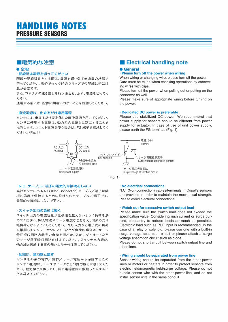
Please use stabilized DC power. We recommend that power supply for sensors should be different from power supply for actuator. In case of use of unit power supply, please earth the FG terminal. (Fig. 1)
全般・配線時は電源を切ってください配線や配線替えをする際は、電源を切り必ず無通電の状態で
行ってください。動作チェック時のクリップでの配線は特に注
意が必要です。
また、コネクタの抜き差しを行う場合も、必ず、電源を切ってく
ださい。
通電する前には、配線に間違いのないことを確認してください。
・直流電源は、出来るだけ専用電源センサには、出来るだけ安定化した直流電源を用いてください。
センサに使用する電源は、動力系の電源とは別にすることを
推奨します。ユニット電源を使う場合は、FG端子を接地してく
ださい。(Fig. 1)
・N.C. ケーブル/端子の電気的な接続をしない当社センサにあるN.C.(Non-Connection)ケーブル/端子は機
械的強度を保持するために設けられたケーブル/端子です。
電気的な接続はしないで下さい。
・スイッチ出力の負荷は軽くスイッチ出力の電流容量が仕様値を越えないように負荷を決
めてください。突入電流やサージ電流などを考え、出来るだけ
軽負荷となるようにしてください。PLC入力など電子式の負荷
を推奨しますリレーやソレノイドなどが負荷の場合は、サージ
電圧吸収回路内蔵品の負荷を選ぶか、外部にダイオードなど
のサージ電圧吸収回路を付けてください。スイッチ出力線が、
他の線と短絡する事の無いよう十分注意してください。
・配線は、動力線と離すセンサを外来の電界/磁界/サージ電圧から保護するため
センサの配線は、モータやヒータなどの動力線とは離してくだ
さい。動力線と束線したり、同じ電線管内に敷設したりするこ
とは避けてください。
■電気的な注意 ■ Electrical handling note
are provided in order to maintain the mechanical strength. Please avoid electrical connections.
Please make sure the switch load does not exceed the specification value. Considering rush current or surge cur-rent, please try to reduce loads as much as possible. Electronic load such as PLC input is recommended. In the case of a relay or solenoid, please use one with a built-in surge volt age absorp tion circuit or please attach a surge voltage absorp tion circuit such as diode.Please do not short circuit between switch output line and other lines.
Sensor wiring should be separated from the other power lines or motors or heaters in order to protect sensors from elec tric field/magnetic field/surge voltage. Please do not bundle sensor wire with the other power line, and do not install sensor wire in the same con duit.
AC 入力AC input
DC 出力DC output
電源(+)Power (+)
コイルソレノイドCoil solenoid サージ電圧吸収素子
Surge voltage absorption element
サージ電圧吸収回路Surge voltage absorption circuit
FG
FG端子を接地FG terminal earth
ユニット電源使用時Unit power supply
(Fig. 1)
HANDLING NOTESPRESSURE SENSORS
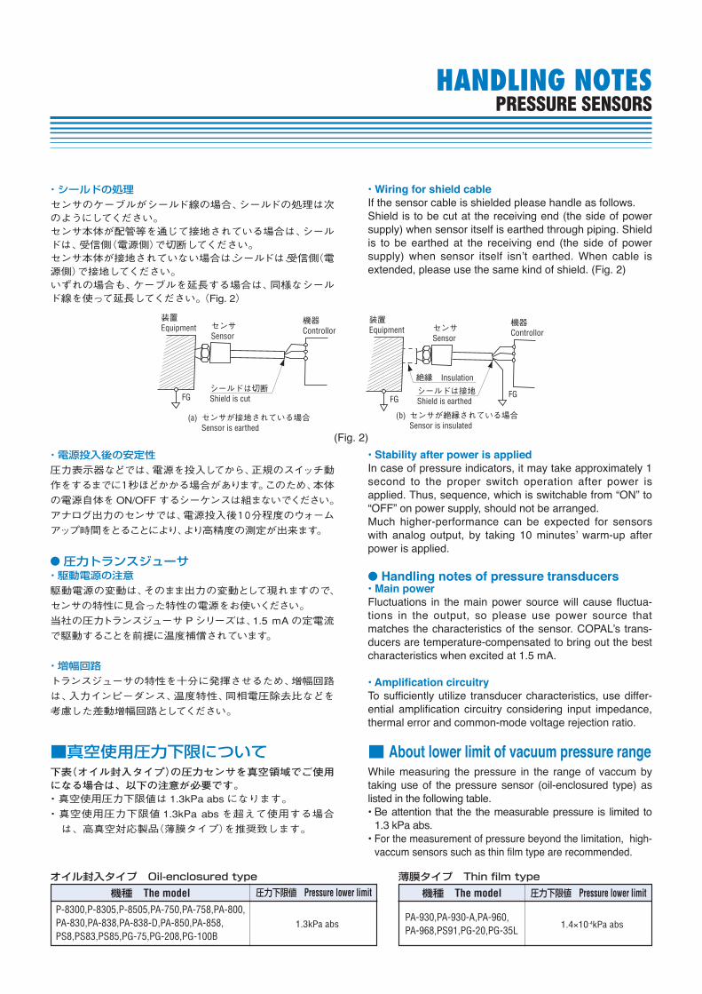
If the sensor cable is shielded please handle as follows.Shield is to be cut at the receiving end (the side of power supply) when sensor itself is earthed through piping. Shield is to be earthed at the receiving end (the side of power
extended, please use the same kind of shield. (Fig. 2)
In case of pressure indicators, it may take approximately 1 second to the proper switch operation after power is applied. Thus, sequence, which is switchable from “ON” to “OFF” on power supply, should not be arranged.Much higher-performance can be expected for sensors
power is applied.
Handling notes of pressure transducers
Fluctuations in the main power source will cause fluctu a-tions in the output, so please use power source that
duc ers are temperature-compensated to bring out the best char acteristics when excited at 1.5 mA.
To sufficiently utilize transducer characteristics, use differ-en tial amplification circuitry considering input impedance, ther mal error and common-mode voltage rejection ratio.
・シールドの処理センサのケーブルがシールド線の場合、シールドの処理は次のようにしてください。センサ本体が配管等を通じて接地されている場合は、シールドは、受信側(電源側)で切断してください。センサ本体が接地されていない場合は、シールドは、受信側(電源側)で接地してください。いずれの場合も、ケーブルを延長する場合は、同様なシールド線を使って延長してください。(Fig. 2)
・電源投入後の安定性圧力表示器などでは、電源を投入してから、正規のスイッチ動
作をするまでに1秒ほどかかる場合があります。このため、本体
の電源自体をON/OFFするシーケンスは組まないでください。
アナログ出力のセンサでは、電源投入後10分程度のウォーム
アップ時間をとることにより、より高精度の測定が出来ます。
圧力トランスジューサ・駆動電源の注意駆動電源の変動は、そのまま出力の変動として現れますので、
センサの特性に見合った特性の電源をお使いください。
当社の圧力トランスジューサPシリーズは、1.5 mAの定電流
で駆動することを前提に温度補償されています。
・増幅回路トランスジューサの特性を十分に発揮させるため、増幅回路
は、入力インピーダンス、温度特性、同相電圧除去比などを
考慮した差動増幅回路としてください。
装置Equipment センサ
Sensor
FG
(a)
機器Controllor
シールドは切断Shield is cut
シールドは接地Shield is earthed
センサが接地されている場合Sensor is earthed
装置Equipment センサ
Sensor
FG
(b)
機器Controllor
絶縁 Insulation
センサが絶縁されている場合Sensor is insulated
FG
(Fig. 2)
While measuring the pressure in the range of vaccum by taking use of the pressure sensor (oil-enclosured type) as listed in the following table.
Be attention that the the measurable pressure is limited to 1.3 kPa abs. For the measurement of pressure beyond the limitation, high-vaccum sensors such as thin film type are recommended.
下表(オイル封入タイプ)の圧力センサを真空領域でご使用になる場合は、以下の注意が必要です。・真空使用圧力下限値は 1.3kPa abs になります。
・真空使用圧力下限値 1.3kPa abs を超えて使用する場合
は、高真空対応製品(薄膜タイプ)を推奨致します。
■真空使用圧力下限について ■ About lower limit of vacuum pressure range
オイル封入タイプ Oil-enclosured type 薄膜タイプ Thin film type
機種 The model 機種 The model圧力下限値 Pressure lower limit 圧力下限値 Pressure lower limitP-8300,P-8305,P-8505,PA-750,PA-758,PA-800,PA-830,PA-838,PA-838-D,PA-850,PA-858,PS8,PS83,PS85,PG-75,PG-208,PG-100B
PA-930,PA-930-A,PA-960,PA-968,PS91,PG-20,PG-35L
1.3kPa abs 1.4×10⁻⁴kPa abs
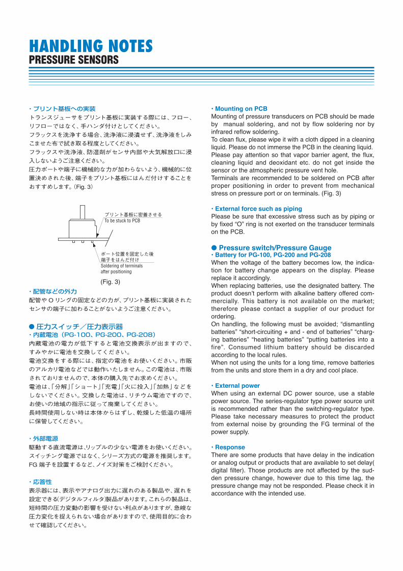
Mounting of pressure transducers on PCB should be made by manual soldering, and not by flow solder ing nor by infrared reflow soldering.To clean flux, please wipe it with a cloth dipped in a clean ing liquid. Please do not immerse the PCB in the cleaning liquid.Please pay attention so that vapor barrier agent, the flux, cleaning liquid and deoxidant etc. do not get inside the sensor or the atmospheric pressure vent hole.Terminals are recommended to be soldered on PCB after proper positioning in order to prevent from mechanical stress on pressure port or on terminals. (Fig. 3)
Please be sure that excessive stress such as by piping or by fixed “O” ring is not exerted on the transducer terminals on the PCB.
Pressure switch/Pressure Gauge
When the voltage of the battery becomes low, the indi ca-tion for battery change appears on the display. Please replace it accordingly.When replacing batteries, use the designated battery. The
mer cial ly. This battery is not available on the market; therefore please con tact a supplier of our product for ordering.On handling, the following must be avoided; “dismantling bat ter ies” “short-circuiting + and - end of batteries” “charg-ing batteries” “heating batteries” “putting batteries into a fire”. Consumed lithium battery should be discarded accord ing to the local rules.When not using the units for a long time, remove batteries from the units and store them in a dry and cool place.
When using an external DC power source, use a stable power source. The series-regulator type power source unit is rec ommended rather than the switching-regulator type. Please take necessary measures to protect the product from external noise by grounding the FG terminal of the power supply.
There are some products that have delay in the indication or analog output or products that are available to set delay( digital filter). Those products are not affected by the sud-den pressure change, however due to this time lag, the pres sure change may not be responded. Please check it in accor dance with the intended use.
・プリント基板への実装トランスジューサをプリント基板に実装する際には、フロー、
リフローではなく、手ハンダ付けとしてください。
フラックスを洗浄する場合、洗浄液に浸漬せず、洗浄液をしみ
こませた布で拭き取る程度としてください。
フラックスや洗浄液、防湿剤がセンサ内部や大気解放口に浸
入しないようご注意ください。
圧力ポートや端子に機械的な力が加わらないよう、機械的に位
置決めされた後、端子をプリント基板にはんだ付けすることを
おすすめします。(Fig. 3)
・配管などの外力配管やOリングの固定などの力が、プリント基板に実装された
センサの端子に加わることがないようご注意ください。
圧力スイッチ/圧力表示器・内蔵電池(PG-100、PG-200、PG-208)内蔵電池の電力が低下すると電池交換表示が出ますので、
すみやかに電池を交換してください。
電池交換をする際には、指定の電池をお使いください。市販
のアルカリ電池などでは動作いたしません。この電池は、市販
されておりませんので、本体の購入先でお求めください。
電池は、「分解」「ショート」「充電」「火に投入」「加熱」などを
しないでください。交換した電池は、リチウム電池ですので、
お使いの地域の指示に従って廃棄してください。
長時間使用しない時は本体からはずし、乾燥した低温の場所
に保管してください。
・外部電源駆動する直流電源は、リップルの少ない電源をお使いください。
スイッチング電源ではなく、シリーズ方式の電源を推奨します。
FG端子を設置するなど、ノイズ対策をご検討ください。
・応答性表示器には、表示やアナログ出力に遅れのある製品や、遅れを
設定できる(デジタルフィルタ)製品があります。これらの製品は、
短時間の圧力変動の影響を受けない利点がありますが、急峻な
圧力変化を捉えられない場合がありますので、使用目的に合わ
せて確認してください。
HANDLING NOTESPRESSURE SENSORS
ポート位置を固定した後端子をはんだ付けSoldering of terminalsafter positioning
プリント基板に密着させるTo be stuck to PCB
(Fig. 3)
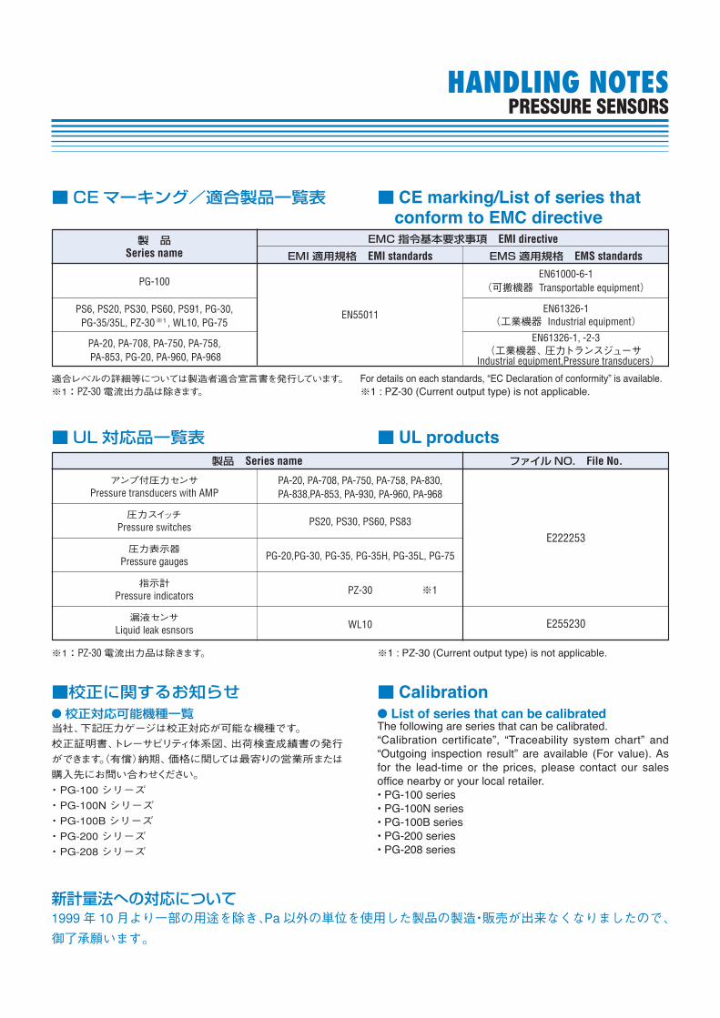
■CEマーキング/適合製品一覧表 ■conform to EMC directive
適合レベルの詳細等については製造者適合宣言書を発行しています。※1:PZ-30電流出力品は除きます。
For details on each standards, “EC Declaration of conformity” is available.※1 : PZ-30 (Current output type) is not applicable.
※1:PZ-30電流出力品は除きます。 ※1 : PZ-30 (Current output type) is not applicable.
■UL対応品一覧表 ■ UL products
List of series that can be calibratedThe following are series that can be calibrated.“Calibration certificate”, “Traceability system chart” and “Outgoing inspection result” are available (For value). As for the lead-time or the prices, please contact our sales office nearby or your local retailer.
校正対応可能機種一覧当社、下記圧力ゲージは校正対応が可能な機種です。
校正証明書、トレーサビリティ体系図、出荷検査成績書の発行
ができます。(有償)納期、価格に関しては最寄りの営業所または
購入先にお問い合わせください。
・PG-100 シリーズ
・PG-100N シリーズ
・PG-100B シリーズ
・PG-200 シリーズ
・PG-208 シリーズ
■校正に関するお知らせ ■ Calibration
製 品Series name
PS6, PS20, PS30, PS60, PS91, PG-30, PG-35/35L, PZ-30 , WL10, PG-75
PA-20, PA-708, PA-750, PA-758, PA-853, PG-20, PA-960, PA-968
PG-100
EN55011
EN61000-6-1(可搬機器 Transportable equipment)
EN61326-1(工業機器 Industrial equipment)
EN61326-1, -2-3(工業機器、圧力トランスジューサ
Industrial equipment,Pressure transducers)
EMC指令基本要求事項 EMI directiveEMI 適用規格 EMI standards EMS適用規格 EMS standards
HANDLING NOTESPRESSURE SENSORS
新計量法への対応について1999 年 10月より一部の用途を除き、Pa以外の単位を使用した製品の製造・販売が出来なくなりましたので、
御了承願います。
製品 Series name
アンプ付圧力センサPressure transducers with AMP
E222253
E255230
PA-20, PA-708, PA-750, PA-758, PA-830, PA-838,PA-853, PA-930, PA-960, PA-968
圧力スイッチPressure switches PS20, PS30, PS60, PS83
PG-20,PG-30, PG-35, PG-35H, PG-35L, PG-75
PZ-30 ※1
WL10
圧力表示器Pressure gauges
指示計Pressure indicators
漏液センサLiquid leak esnsors
ファイルNO. File No.
※1
HANDLING NOTESPRESSURE SENSORS
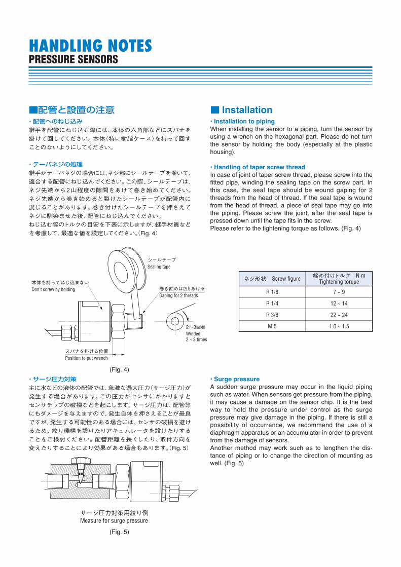
When installing the sensor to a piping, turn the sensor by using a wrench on the hexagonal part. Please do not turn the sensor by holding the body (especially at the plastic hous ing).
In case of joint of taper screw thread, please screw into the fitted pipe, winding the sealing tape on the screw part. In this case, the seal tape should be wound gaping for 2 threads from the head of thread. If the seal tape is wound from the head of thread, a piece of seal tape may go into the piping. Please screw the joint, after the seal tape is pressed down until the tape fits in the screw.Please refer to the tightening torque as follows. (Fig. 4)
A sudden surge pressure may occur in the liquid piping such as water. When sensors get pressure from the piping, it may cause a damage on the sensor chip. It is the best way to hold the pressure under control as the surge pressure may give damage in the piping. If there is still a possibility of occur rence, we recommend the use of a diaphragm appa ra tus or an accumulator in order to prevent from the damage of sensors.Another method may work such as to lengthen the dis-tance of piping or to change the direction of mounting as well. (Fig. 5)
・配管へのねじ込み継手を配管にねじ込む際には、本体の六角部などにスパナを
掛けて回してください。本体(特に樹脂ケース)を持って回す
ことのないようにしてください。
・テーパネジの処理継手がテーパネジの場合には、ネジ部にシールテープを巻いて、
適合する配管にねじ込んでください。この際、シールテープは、
ネジ先端から2山程度の隙間をあけて巻き始めてください。
ネジ先端から巻き始めると裂けたシールテープが配管内に
混じることがあります。巻き付けたシールテープを押さえて
ネジに馴染ませた後、配管にねじ込んでください。
ねじ込む際のトルクの目安を下表に示しますが、継手材質など
を考慮して、最適な値を設定してください。(Fig. 4)
・サージ圧力対策主に水などの液体の配管では、急激な過大圧力(サージ圧力)が
発生する場合があります。この圧力がセンサにかかりますと
センサチップの破損などを起こします。サージ圧力は、配管等
にもダメージを与えますので、発生自体を押さえることが最良
ですが、発生する可能性のある場合には、センサの破損を避け
るため、絞り機構を設けたりアキュムレータを設けたりする
ことをご検討ください。配管距離を長くしたり、取付方向を
変えたりすることにより効果がある場合もあります。(Fig. 5)
■配管と設置の注意 ■ Installation
ネジ形状 Screw figure 締め付けトルク N·mTightening torque
R 1/8
R 1/4
R 3/8
M 5
7 ~ 9
12 ~ 14
22 ~ 24
1.0 ~ 1.5
サージ圧力対策用絞り例Measure for surge pressure
本体を持ってねじ込まないDon’t screw by holding
シールテープSealing tape
巻き始めは2山あけるGaping for 2 threads
スパナを掛ける位置Position to put wrench
2~3回巻Winded 2 ~ 3 times
(Fig. 4)
(Fig. 5)
Pa(N/m2)
Pa(N/m2) kPaMPabarmbar(hPa)kgf/cm2
mmH2O(mmAq)inH2OmmHg(Torr)inHgpsiatm
kPa MPa bar mbar(hPa) kgf/cm2 mmH2O(mmAq) inH2O mmHg(Torr) inHg psi atm
1
1 × 10³
1 × 10⁶
1 × 10⁵
1 × 10²
9.80665 × 10⁴
9.80638
2.49082 × 10²
1.33322 × 10²
3.38639 ¥ 103
6.89476 × 10³
1.01325 × 10⁵
1 × 10⁻³
1
1 × 10³
1 × 10²
1 × 10⁻¹
9.80665 × 10
9.80638 × 10⁻³
2.49082 × 10⁻¹
1.33322 × 10⁻¹
3.38639
6.89476
1.01325 × 10²
1 × 10⁻⁶
1 × 10⁻³
1
1 × 10⁻¹
1 × 10⁻⁴
9.80665 × 10⁻²
9.80638 × 10⁻⁶
2.49082 × 10⁻⁴
1.33322 × 10⁻⁴
3.38639 × 10⁻³
6.89476 × 10⁻³
1.01325 × 10⁻¹
1 × 10⁻⁵
1 × 10⁻²
1 × 10
1
1 × 10⁻³
9.80665 × 10⁻¹
9.80638 × 10⁻⁵
2.49082 × 10⁻³
1.33322 × 10⁻³
3.38639 × 10⁻²
6.89476 × 10⁻²
1.01325
1 × 10
1 × 10⁴
1 × 10³
1
9.80665 × 10²
9.80638 × 10⁻²
2.49082
1.33322
3.38639 × 10
6.89476 × 10
1.01325 × 10³
1.01972 × 10⁻²
1.01972 × 10
1.01972
1.01972 × 10⁻³
1
9.99972 × 10⁻⁵
2.53993 × 10⁻³
1.35951 × 10⁻³
3.45316 × 10⁻²
7.03070 × 10⁻²
1.03323
1.01974 × 10²
1.01974 × 10⁵
1.01974 × 10⁴
1.01974 × 10
1.00003 × 10⁴
1
2.54000 × 10
1.35955 × 10
3.45325 × 10²
7.03089 × 10²
1.03326 × 10⁴
4.01474
4.01474 × 10³
4.01474 × 10²
4.01474 × 10⁻¹
3.93712 × 10²
3.93701 × 10⁻²
1
5.35255 × 10⁻¹
1.35955 × 10
2.768076 × 10
4.06794 × 10²
7.50062
7.50062 × 10³
7.50062 × 10²
7.50062 × 10⁻¹
7.35559 × 10²
7.35559 × 10⁻²
1.86827
1
2.54000 × 10
5.17149 × 10
7.60000 × 10²
2.95300 × 10⁻¹
2.95300 × 10²
2.95300 × 10
2.95300 × 10⁻²
2.89590 × 10
2.89582 × 10⁻³
7.35539 × 10⁻²
3.93701 × 10⁻²
1
2.03602
2.99213 × 10
1.45038 × 10⁻¹
1.45038 × 10²
1.45038 × 10
1.45038 × 10⁻²
1.42233 × 10
1.42229 × 10⁻³
3.61263 × 10⁻²
1.93368 × 10⁻²
4.91154 × 10⁻¹
1
1.46960 × 10
9.86923 × 10⁻³
9.86923
9.86923 × 10⁻¹
9.86923 × 10⁻⁴
9.67841 × 10⁻¹
9.67814 × 10⁻⁵
2.45825 × 10⁻³
1.31579 × 10⁻³
3.34211 × 10⁻²
6.80460 × 10⁻²
1
1 × 10⁻² 1.01972 × 10⁻⁵ 1.01974 × 10⁻¹ 4.01474 × 10⁻³ 7.50062 × 10⁻³ 2.95300 × 10⁻⁴ 1.45038 × 10⁻⁴ 9.86923 × 10⁻⁶
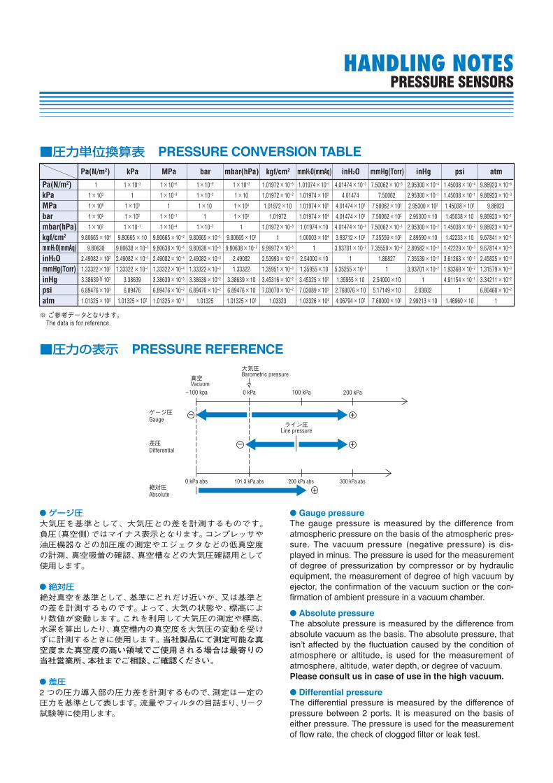
■圧力単位換算表
■圧力の表示 大気圧Barometric pressure
真空Vacuum
ライン圧Line pressure
ゲージ圧Gauge
差圧Differential
絶対圧Absolute
– +
– +
+
–100 kpa 0 kPa 100 kPa 200 kPa
300 kPa abs200 kPa abs101.3 kPa abs0 kPa abs
ゲージ圧大気圧を基準として、大気圧との差を計測するものです。負圧(真空側)ではマイナス表示となります。コンプレッサや油圧機器などの加圧度の測定やエジェクタなどの低真空度の計測、真空吸着の確認、真空槽などの大気圧確認用として使用します。
絶対圧絶対真空を基準として、基準にどれだけ近いか、又は基準との差を計測するものです。よって、大気の状態や、標高により数値が変動します。これを利用して大気圧の測定や標高、水深を算出したり、真空槽内の真空度を大気圧の変動を受けずに計測するときに使用します。当社製品にて測定可能な真空度また真空度の高い領域でご使用される場合は最寄りの当社営業所、本社までご相談、ご確認ください。
差圧2 つの圧力導入部の圧力差を計測するもので、測定は一定の圧力を基準として表します。流量やフィルタの目詰まり、リーク試験等に使用します。
Gauge pressureThe gauge pressure is measured by the difference from atmos pheric pressure on the basis of the atmospheric pres -sure. The vacuum pressure (negative pressure) is dis-played in minus. The pressure is used for the mea sure ment of degree of pressurization by compressor or by hydraulic equip ment, the measurement of degree of high vac u um by ejector, the confirmation of the vacuum suction or the con-fir ma tion of ambient pressure in a vacuum cham ber.
Absolute pressureThe absolute pressure is measured by the difference from absolute vacuum as the basis. The absolute pressure, that
atmos phere or altitude, is used for the measurement of atmos phere, altitude, water depth, or degree of vacuum.
Differential pressureThe differential pressure is measured by the difference of pressure between 2 ports. It is measured on the basis of either pressure. The pressure is used for the measurement of flow rate, the check of clogged filter or leak test.
HANDLING NOTESPRESSURE SENSORS
※ご参考データとなります。The data is for reference.
一般仕様・定格圧力 圧力センサの仕様を保証する圧力値。
・最大圧力 圧力センサに印加できる最大の圧力値。定
格圧力をこえ最大圧力を印加後、定格圧力
内でのセンサ特性の仕様は保証。(但し、オフ
セット電圧/ゼロ電圧は変化する可能性が有
ります。)
・破壊圧力 圧力センサが電気的又は機械的に破壊する
圧力値。この場合は、測定中の圧力媒体が
外部へ漏れだす可能性が高く注意が必要。
・補償温度 圧力センサの仕様値を保証している温度範囲。
当社の圧力センサは、一般的に0 °C~50 °C
の範囲。
・動作温度 圧力センサが破損しない温度範囲。補償温
度を超えて使用する場合は、仕様値は保証で
きないが動作は可能。
・保存温度 圧力センサが破損せず保存できる温度範囲。
但し、保存の状態は、無負荷(電源、圧力が
印加されていない)の事。
・動作湿度 圧力センサが破損せず動作できる湿度範囲。
但し、急激な温度変化などにより圧力センサ
に結露が生じた場合、破損する可能性があり
注意が必要。
・ブリッジ抵抗 圧力センサの入力端子間の抵抗値。入力
端子・出力端子ともに開放された状態。
General specifications
The maximum value of the pressure at which all the specifications of the pressure sensor can be met or the value of the pressure which can be continuously applied to the pressure sensor without losing the performance characteristics to meet all the sensor specifications.
The maximum pressure which can be applied to the pressure sensor. The sensor specifications are to be met even after the maximum pressure is applied to the sensor for a short period of time. (However, there is a possibi l i ty that the offset voltage/zero voltage changes.)
The pressure at which the pressure sensor is mechanically or electrically damaged.It should be noted that at this pressure, pressure media may leak out from the pressure sensor.
The temperature range within which the sensor specifications are satisfied.Our standard pressure sensors are compensated for a temperature range of 0 to 50 °C.
The temperature range within which the pressure sensor can be used without causing any permanent damage.Pressure sensors may be used at a temperature beyond the compensated temperature range but within the operating temperature range. However, in this case, sensor specifications may not be met.
The temperature range within which the pressure sensor can be stored without causing any permanent change in the sensor speci f icat ions. No load conditions, namely, no power supply and no pressure application are assumed for the storage.
The humidity range within which the pressure sensor can be operated without causing any permanent change in the sensor specifications.It is to be noted that the condensation that may be generated due to a rapid temperature change may damage the pressure sensor.
The resistance between the input terminals of the pressure sensor which is measured with the input and output terminals open.
GLOSSARYPRESSURE SENSORS 用語の説明
GLOSSARYPRESSURE SENSORS
・適用媒体 圧力センサが使用できる流体。当社の圧力
センサは、測定する流体により気体用、気
体/液体用に分類。
・絶縁抵抗 圧力センサのハウジング(圧力ポート)とセン
サ回路間の直流抵抗値。
・耐電圧 圧力センサのハウジング(圧力ポート)とセン
サ回路間に印加しても漏れ電流が流れない
交流電圧値。
・駆動電圧/電流 圧力センサを駆動(動作)するため
の供給電圧/電流。一般的に圧力
トランスジューサ Pシリーズは直流
電流駆動、その他の圧力センサは
直流電圧駆動。
アナログ出力・オフセット電圧 圧力センサに圧力を加えない時の出
力電圧。但し、絶対圧タイプの圧力
センサは絶対真空の時の出力電圧。
・ゼロ電圧/電流 圧力センサに圧力を加えない時の
出力。但し、絶対圧タイプの圧力
センサは、絶対真空の時の出力。
・スパン電圧/電流 圧力センサに定格圧力を加えた時の
出力とゼロ電圧/電流との差。
・直線性 圧力センサに無負荷から定格圧力を加えた
時、無負荷と定格圧力を結ぶ出力の直線と
実測値の差。(Fig. 1)
誤差はスパン出力に対する百分率(%F.S.)
で表示。
・ヒステリシス 圧力センサに圧力を無負荷より定格圧力ま
で増加し定格圧力より無負荷まで減少させた
時の出力の同一圧力値における最大差。誤
差は、スパン出力に対する百分率(%F.S.)で
表示。(Fig. 1)
Our pressure sensors consist of two compatible fluids type: Gases only and gases and liquids.
The DC resistance between the housing of the pressure sensor (pressure port) and the sensor circuit.
The AC voltage which can be applied between the housing of the pressure sensor and the sensor circuit without leakage current.
The supply voltage/current to operate the pressure sensor.Our standard pressure sensors without amplifier is excited by current, whereas other pressure sensors are driven by voltage.
Analog output
The output voltage when no pressure is applied to the pressure sensor.In the case of absolute pressure type pressure sen-sors, the offset voltage is at the absolute vacuum.
The output when no pressure is applied to the pres-sure sensor.In the case of absolute pressure type, zero voltage / current is at the absolute vacuum.
The difference between the output when rated pressure is applied to the pressure sensor and the zero voltage/current.
The maximum deviation of the actually measured output from the linear output which is defined by connecting the no load output and rated output points when the pressure is increased from no load to the rated pressure. (Fig. 1) The error is expressed in percent against the span output.
The maximum difference between the output when the pressure to the pressure sensor is increased from no load to the rated pressure and the output when the pressure is decreased from the rated pressure to no load. The error is expressed in percent against the span output. (Fig. 1)
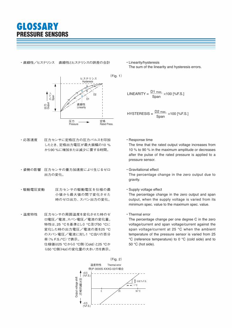
・直線性/ヒステリシス 直線性とヒステリシスの誤差の合計The sum of the linearity and hysteresis errors.
LINEARITY = ×100 [%F.S.]D1 max.Span
HYSTERESIS = ×100 [%F.S.]D2 max.Span
ヒステリシスHysteresis
直線性Linearity
圧力Pressure
定格Rated Press.
出力
Out
putスパン
Span
D1
D2
(Fig. 1)
・応答速度 圧力センサに定格圧力の圧力パルスを印加
したとき、定格出力電圧が最大振幅の10 %
から90 %に増加または減少に要する時間。
・姿勢の影響 圧力センサの重力加速度により生じるゼロ
出力の変化。
・駆動電圧変動 圧力センサの駆動電圧を仕様の最
小値から最大値の間で変化させた
時のゼロ出力、スパン出力の変化。
・温度特性 圧力センサの周囲温度を変化させた時のゼ
ロ電圧/電流、スパン電圧/電流の変化量。
特性は、25 °Cを基準とし0 °C及び50 °Cに
変化した時の出力電圧/電流の差を25 °C
のスパン電圧/電流に対し1 °C当りの百分
率(% F.S./°C)で表示。
仕様値は25 °Cから0 °C側(Cold)と25 °Cか
ら50 °C側(Hot)の変化量の大きい方を表示。
The time that the rated output voltage increases from 10 % to 90 % in the maximum amplitude or decreases after the pulse of the rated pressure is applied to a pressure sensor.
The percentage change in the zero output due to gravity.
The percentage change in the zero output and span output, when the supply voltage is varied from its minimum spec. value to the maximum spec. value.
The percentage change per one degree C in the zero voltage/current and span voltage/current against the span voltage/current at 25 °C when the ambient temperature of the pressure sensor is varied from 25 °C (reference temperature) to 0 °C (cold side) and to 50 °C (hot side).
+0.5(%F.S.)
Out
put v
olta
ge s
hift
出力電圧変化
–0.5(%F.S.)
0 25 50 °C
0.02 % F.S.
1 °C
温度特性 Thermal error例)P-3000S-XXXG-02の場合
(Fig. 2)
GLOSSARYPRESSURE SENSORS
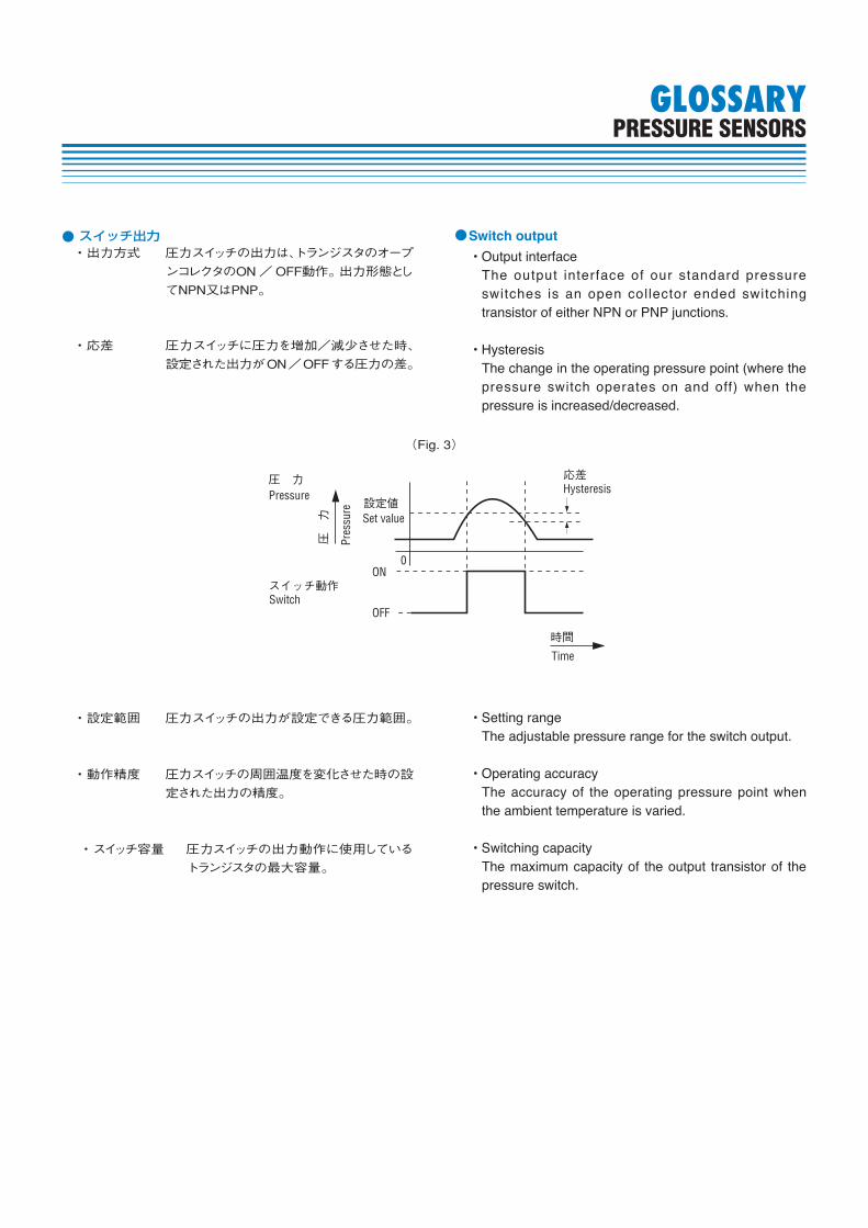
スイッチ出力・出力方式 圧力スイッチの出力は、トランジスタのオープ
ンコレクタのON/OFF動作。出力形態とし
てNPN又はPNP。
・応差 圧力スイッチに圧力を増加/減少させた時、
設定された出力がON/OFFする圧力の差。
Switch output
The output interface of our standard pressure switches is an open collector ended switching transistor of either NPN or PNP junctions.
The change in the operating pressure point (where the pressure switch operates on and off) when the pressure is increased/decreased.
設定値
圧 力
スイッチ動作
圧 力
応差Hysteresis
0ON
Set value
Pres
sure
Switch
Pressure
OFF
時間
Time
(Fig. 3)
・設定範囲 圧力スイッチの出力が設定できる圧力範囲。
・動作精度 圧力スイッチの周囲温度を変化させた時の設
定された出力の精度。
・スイッチ容量 圧力スイッチの出力動作に使用している
トランジスタの最大容量。
The adjustable pressure range for the switch output.
The accuracy of the operating pressure point when the ambient temperature is varied.
The maximum capacity of the output transistor of the pressure switch.
GLOSSARYPRESSURE SENSORS
表示・定格表示 圧力表示器/指示計の定格圧力に対する
表示。
・表示回数 圧力表示器/指示計の一定時間に表示す
る回数。
・表示精度 圧力表示器/指示計の周囲温度一定時の
表示の精度。
環境試験・振動 圧力センサに規定の周波数、振幅をX, Y, Z
方向に一定時間与える。
・衝撃 圧力センサに規定の衝撃をX, Y, Z 方向に
一定回数与える。
・圧力サイクル 圧力センサに無負荷から定格圧力を1サ
イクルとして規定回数与える。
・耐湿度 圧力センサを規定の温度・湿度の雰囲気に
一定時間放置する。
※環境試験に関する条件は、圧力センサ毎に規定し、その判定
は出力電圧/電流、スイッチ出力設定値、圧力表示をスパン
電圧/電流又は定格圧力に対する百分率で表示。
Display (for pressure gauges and pressure monitors)
The range of pressure displayed and is from a no load value to the rated pressure.
The number of display cycles per second.
The display accuracy when the ambient temperature of the display is varied.
Environmental test
This test checks for the effect the pressure sensor undergoes after the vibration of certain frequency and certain amplitude is applied to the pressure sensor for a specified period of time.
This test checks for the effect on the pressure sensor after the shock of certain magnitude and certain wave shape is applied to the pressure sensor a specified number of times.
The pressure sensor is checked after the application of no load and rated pressure is repeated a specified number of times.
The effect on the pressure sensor is checked after the sensor is subjected to a high temperature and high humidity condition for a specified period of time.
※The environmental test conditions for the above tests are specified for each product individually.The effect of the test is checked in terms of a percentage change in the output voltage/current, switch output settings and displayed pressure against either the span voltage/current or the rated pressure.
GLOSSARYPRESSURE SENSORS
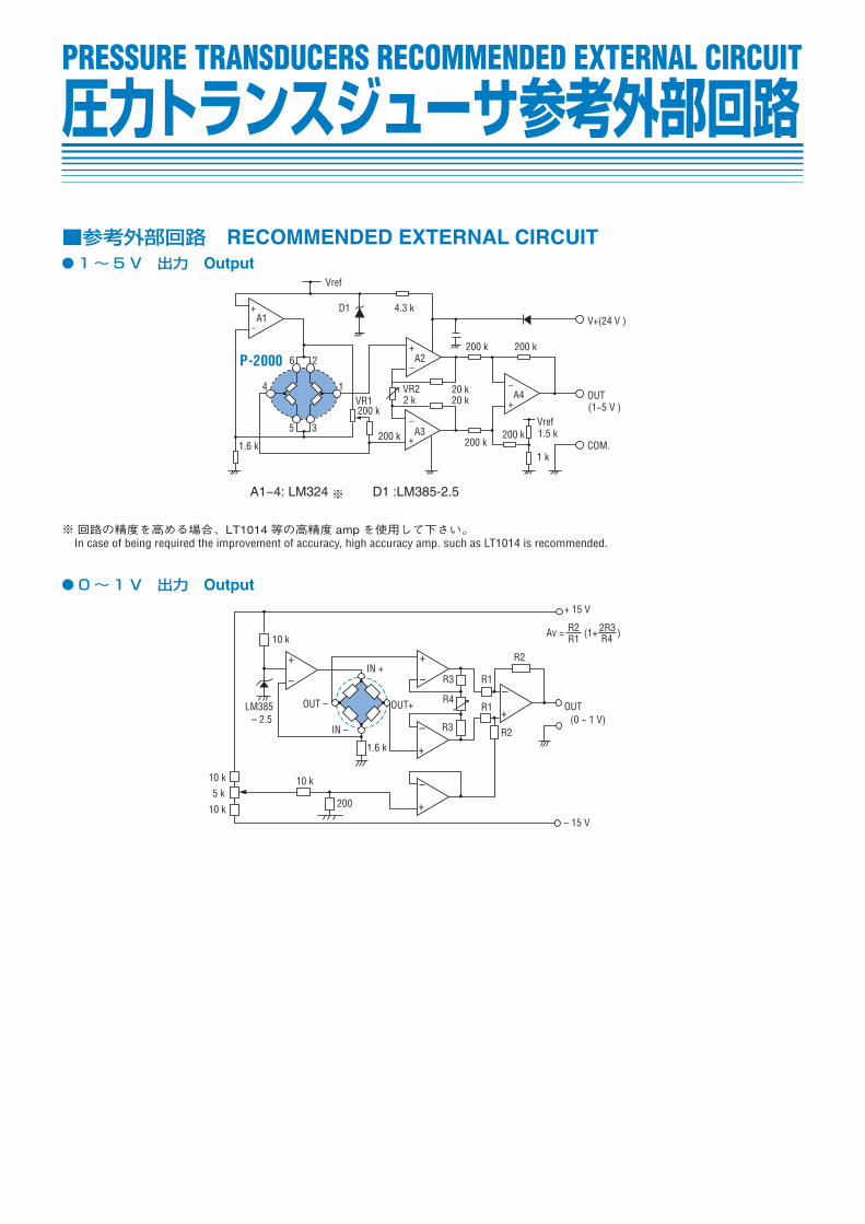
■参考外部回路 RECOMMENDED EXTERNAL CIRCUIT1~ 5 V 出力 Output
0~ 1 V 出力 Output
圧力トランスジューサ参考外部回路PRESSURE TRANSDUCERS RECOMMENDED EXTERNAL CIRCUIT
1.6 k
5
4
6 2
1
3
A1
Vref
D1 4.3 k
A2
VR22 kVR1
200 k
200 k A3200 k
200 k
200 k 200 k
20 k20 k
1 k
1.5 kVref
A4
A1~4: LM324 D1 :LM385-2.5
V+(24 V )
OUT(1~5 V )
COM.
+
_
+_
+_
+
_
P-2000
1.6 k
200
10 k5 k
10 k
10 k
– 2.5LM385
10 k
OUT –
IN +
OUT+
IN –
R3
R4
R3
R1
R1
R2
R2
OUT(0 ~ 1 V)
– 15 V
+ 15 V
Av = R2R1 (1+ 2R3
R4 )
+
–
+
–
–
+
–
+
–
+
※回路の精度を高める場合、LT1014 等の高精度 ampを使用して下さい。 In case of being required the improvement of accuracy, high accuracy amp. such as LT1014 is recommended.
※
Red
White
Black
R
2 4 V
5 V
C O M
V +
O U T
C O M
R : 4.7 kΩ (TTL)
20 kΩ (C-MOS)
シーケンサ
V +
O U T
C O M
Red
White
Black
DC OUT
IN
Common
2 4 V
1/10
V +
O U T
C O M
Red
White
Black I
I
圧力スイッチ
O U T
C O M Black
White
Pressure Switch
圧力スイッチPressure Switch
圧力スイッチPressure SwitchSequencer
圧力スイッチPressure Switch
Relay
D : 逆起電圧吸収回路
Back voltage protection circuit
D
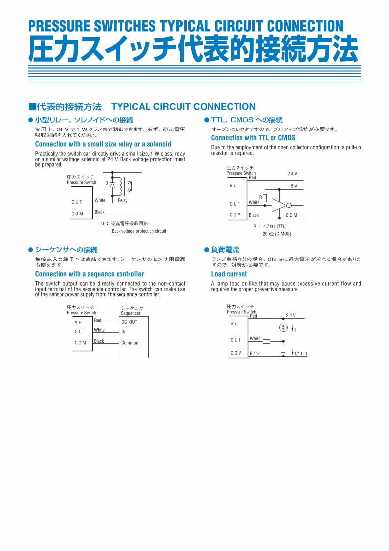
小型リレー、ソレノイドへの接続実用上、24 Vで1 Wクラスまで制御できます。必ず、逆起電圧吸収回路を入れてください。
Connection with a small size relay or a solenoidPractically the switch can directly drive a small size, 1 W class, relay or a similar wattage solenoid at 24 V. Back voltage protection must be prepared.
シーケンサへの接続無接点入力端子へは直結できます。シーケンサのセンサ用電源も使えます。
Connection with a sequence controllerThe switch output can be directly connected to the non-contact input terminal of the sequence controller. The switch can make use of the sensor power supply from the sequence controller.
TTL、CMOSへの接続オープンコレクタですので、プルアップ抵抗が必要です。
Connection with TTL or CMOSDue to the employment of the open collector configuration, a pull-up resistor is required.
負荷電流ランプ負荷などの場合、ON時に過大電流が流れる場合がありますので、対策が必要です。
Load currentA lamp load or like that may cause excessive current flow and requires the proper preventive measure.
■代表的接続方法 TYPICAL CIRCUIT CONNECTION
圧力スイッチ代表的接続方法PRESSURE SWITCHES TYPICAL CIRCUIT CONNECTION