Embed Size (px)
Citation preview
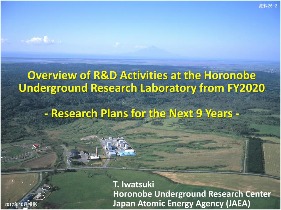
T. IwatsukiHoronobe Underground Research CenterJapan Atomic Energy Agency (JAEA)
Overview of R&D Activities at the Horonobe Underground Research Laboratory from FY2020
- Research Plans for the Next 9 Years -
資料26-2
2012年10月撮影
Buffering capacity test Influence on EBS test
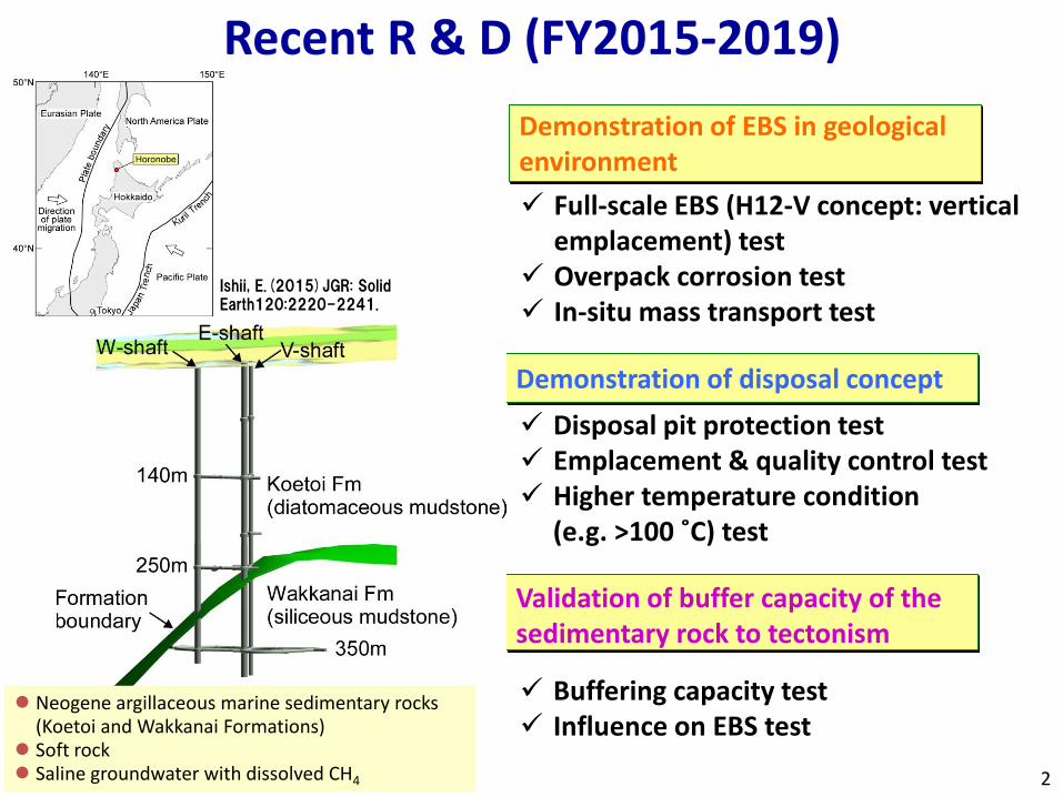
Demonstration of EBS in geological environment
Demonstration of disposal concept
Validation of buffer capacity of the sedimentary rock to tectonism
Full-scale EBS (H12-V concept: vertical emplacement) test
Overpack corrosion test In-situ mass transport test
Disposal pit protection test Emplacement & quality control test Higher temperature condition
(e.g. >100 ˚C) test
Recent R & D (FY2015-2019)
2
Neogene argillaceous marine sedimentary rocks (Koetoi and Wakkanai Formations)
Soft rock Saline groundwater with dissolved CH4
Ishii, E.(2015)JGR: Solid Earth120:2220-2241.
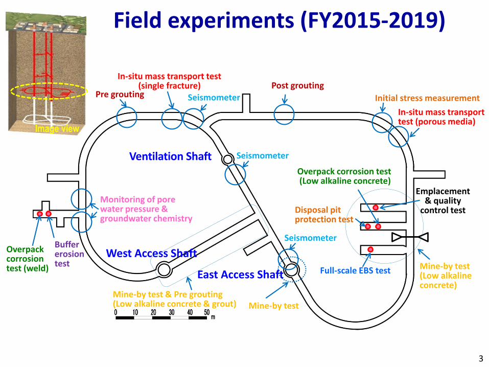
Emplacement & quality
control test
Full-scale EBS test
Monitoring of pore water pressure & groundwater chemistry
Ventilation Shaft
East Access Shaft
West Access Shaft
Post grouting
Initial stress measurement
In-situ mass transport test (porous media)
In-situ mass transport test (single fracture)
Seismometer
Seismometer
Seismometer
Pre grouting
Overpack corrosion test (weld)
Buffer erosion test
Overpack corrosion test(Low alkaline concrete)
Disposal pit protection test
Mine-by test(Low alkaline concrete)
Mine-by testMine-by test & Pre grouting(Low alkaline concrete & grout)
Field experiments (FY2015-2019)
3
Image view
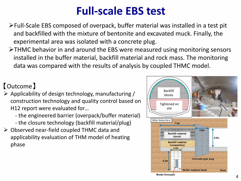
Full-Scale EBS composed of overpack, buffer material was installed in a test pit and backfilled with the mixture of bentonite and excavated muck. Finally, the experimental area was isolated with a concrete plug.
THMC behavior in and around the EBS were measured using monitoring sensors installed in the buffer material, backfill material and rock mass. The monitoring data was compared with the results of analysis by coupled THMC model.
Backfill blocks
Tightened on site
【Outcome】 Applicability of design technology, manufacturing /
construction technology and quality control based on H12 report were evaluated for…
- the engineered barrier (overpack/buffer material)- the closure technology (backfill material/plug)
Observed near-field coupled THMC data and applicability evaluation of THM model of heating phase
Full-scale EBS test
4
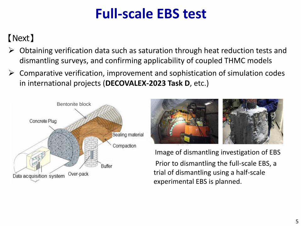
Image of dismantling investigation of EBS
Prior to dismantling the full-scale EBS, a trial of dismantling using a half-scale experimental EBS is planned.
【Next】
Obtaining verification data such as saturation through heat reduction tests and dismantling surveys, and confirming applicability of coupled THMC models
Comparative verification, improvement and sophistication of simulation codes in international projects (DECOVALEX-2023 Task D, etc.)
5
Full-scale EBS test
Bentonite block
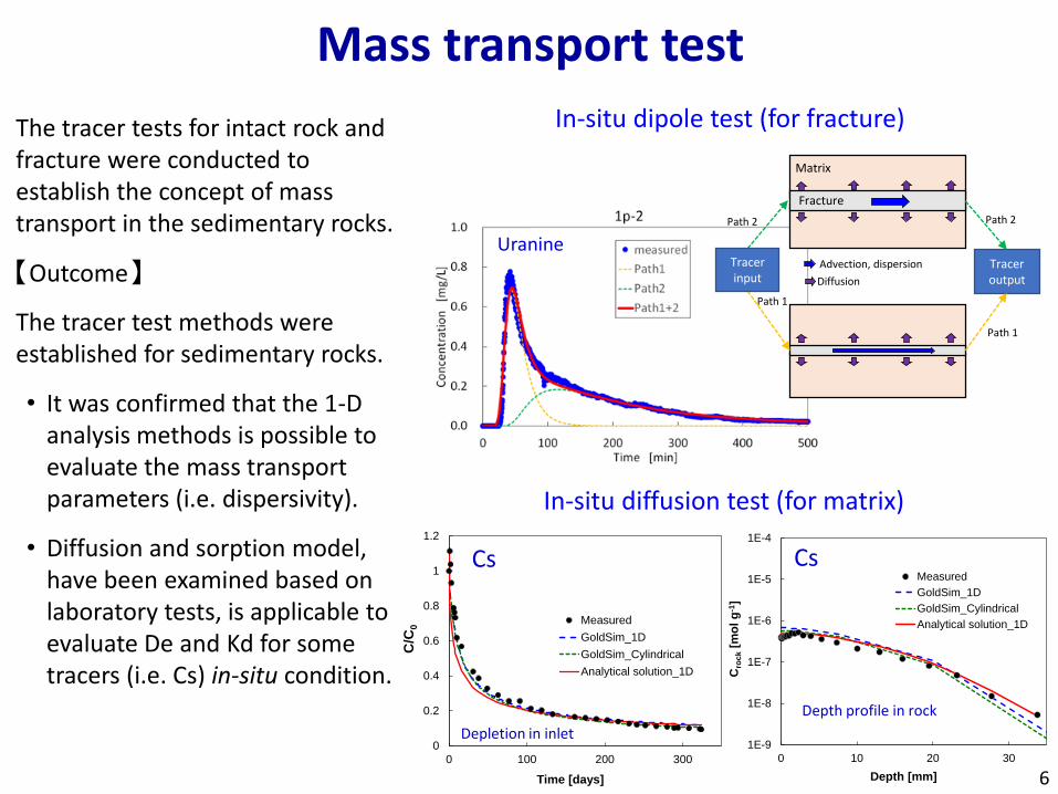
Mass transport test
The tracer tests for intact rock and fracture were conducted to establish the concept of mass transport in the sedimentary rocks.
【Outcome】
The tracer test methods were established for sedimentary rocks.
• It was confirmed that the 1-D analysis methods is possible to evaluate the mass transport parameters (i.e. dispersivity).
• Diffusion and sorption model, have been examined based on laboratory tests, is applicable to evaluate De and Kd for some tracers (i.e. Cs) in-situ condition.
In-situ diffusion test (for matrix)
0
0.2
0.4
0.6
0.8
1
1.2
0 100 200 300
C/C
0
Time [days]
Measured
GoldSim_1D
GoldSim_Cylindrical
Analytical solution_1D
1E-9
1E-8
1E-7
1E-6
1E-5
1E-4
0 10 20 30
Cro
ck
[mo
l g
-1]
Depth [mm]
Measured
GoldSim_1D
GoldSim_Cylindrical
Analytical solution_1D
Depth profile in rock
Cs Cs
Depletion in inlet
In-situ dipole test (for fracture)
Advection, dispersion
Matrix
Fracture
Diffusion
Tracer output
Tracer input
Path 2 Path 2
Path 1
Path 1
Uranine
6
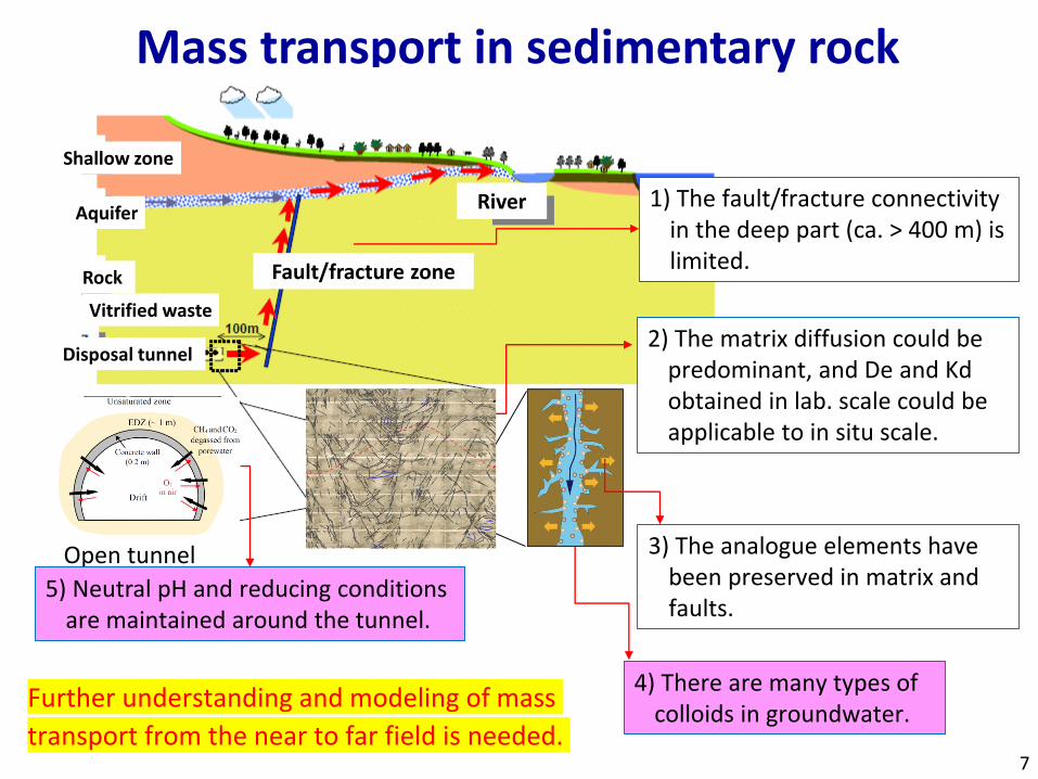
Mass transport in sedimentary rock
Open tunnel
Disposal tunnel
Rock
Aquifer
Shallow zone
River
Fault/fracture zone
Vitrified waste
2) The matrix diffusion could be predominant, and De and Kd obtained in lab. scale could be applicable to in situ scale.
1) The fault/fracture connectivity in the deep part (ca. > 400 m) is limited.
4) There are many types of colloids in groundwater.
3) The analogue elements have been preserved in matrix and faults.
5) Neutral pH and reducing conditions are maintained around the tunnel.
Further understanding and modeling of mass
transport from the near to far field is needed.7
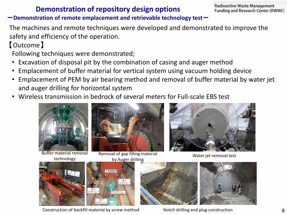
Demonstration of repository design options-Demonstration of remote emplacement and retrievable technology test-
The machines and remote techniques were developed and demonstrated to improve the safety and efficiency of the operation. 【Outcome】Following techniques were demonstrated;• Excavation of disposal pit by the combination of casing and auger method• Emplacement of buffer material for vertical system using vacuum holding device• Emplacement of PEM by air bearing method and removal of buffer material by water jet
and auger drilling for horizontal system• Wireless transmission in bedrock of several meters for Full-scale EBS test
Notch drilling and plug constructionConstruction of backfill material by screw method
下部狭隘部
左上スクリュー
左下スクリュー
右上スクリュー
下スクリュー
Buffer material removal technology
Removal of gap filling material by Auger drilling
Water jet removal test
8
Demonstration of repository design options-Demonstration of remote emplacement-
9
The original version of this slide contains a video that shows
the site activities of the remote emplacement experiment.
Demonstration of repository design options-Demonstration of retrievable technology-
10
The original version of this slide contains a video that shows
the site activities of the retrievable technology experiment.
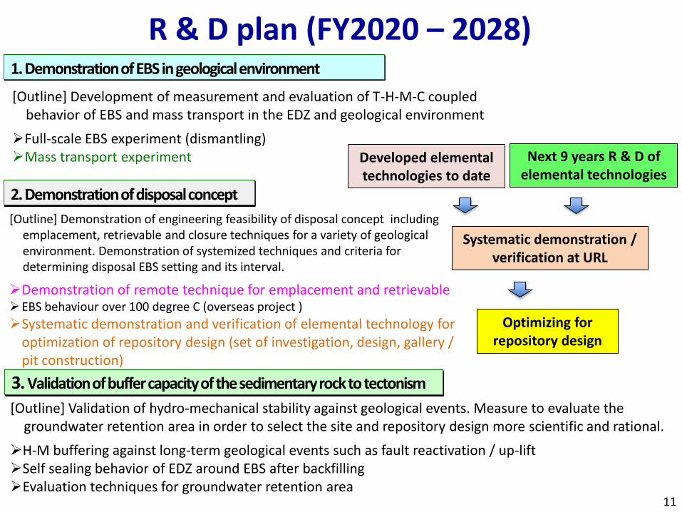
1. Demonstration of EBS in geological environment
[Outline] Development of measurement and evaluation of T-H-M-C coupled behavior of EBS and mass transport in the EDZ and geological environment
Full-scale EBS experiment (dismantling)Mass transport experiment
2. Demonstration of disposal concept
[Outline] Demonstration of engineering feasibility of disposal concept including emplacement, retrievable and closure techniques for a variety of geological environment. Demonstration of systemized techniques and criteria for determining disposal EBS setting and its interval.
Demonstration of remote technique for emplacement and retrievableEBS behaviour over 100 degree C (overseas project )
Systematic demonstration and verification of elemental technology for optimization of repository design (set of investigation, design, gallery / pit construction)
R & D plan (FY2020 – 2028)
[Outline] Validation of hydro-mechanical stability against geological events. Measure to evaluate the groundwater retention area in order to select the site and repository design more scientific and rational.
H-M buffering against long-term geological events such as fault reactivation / up-liftSelf sealing behavior of EDZ around EBS after backfillingEvaluation techniques for groundwater retention area
3. Validation of buffer capacity of the sedimentary rock to tectonism
11
Developed elemental technologies to date
Systematic demonstration / verification at URL
Optimizing forrepository design
Next 9 years R & D ofelemental technologies
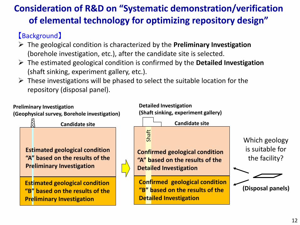
Consideration of R&D on “Systematic demonstration/verification of elemental technology for optimizing repository design”
【Background】 The geological condition is characterized by the Preliminary Investigation
(borehole investigation, etc.), after the candidate site is selected. The estimated geological condition is confirmed by the Detailed Investigation
(shaft sinking, experiment gallery, etc.). These investigations will be phased to select the suitable location for the
repository (disposal panel).
Candidate site
Preliminary Investigation(Geophysical survey, Borehole investigation)
Estimated geological condition “A” based on the results of the Preliminary Investigation
Candidate site
Detailed Investigation(Shaft sinking, experiment gallery)
Confirmed geological condition “A” based on the results of the Detailed Investigation
Confirmed geological condition “B” based on the results of the Detailed Investigation
Shaf
t
Which geology is suitable for the facility?
(Disposal panels)
12
Estimated geological condition “B” based on the results of the Preliminary Investigation
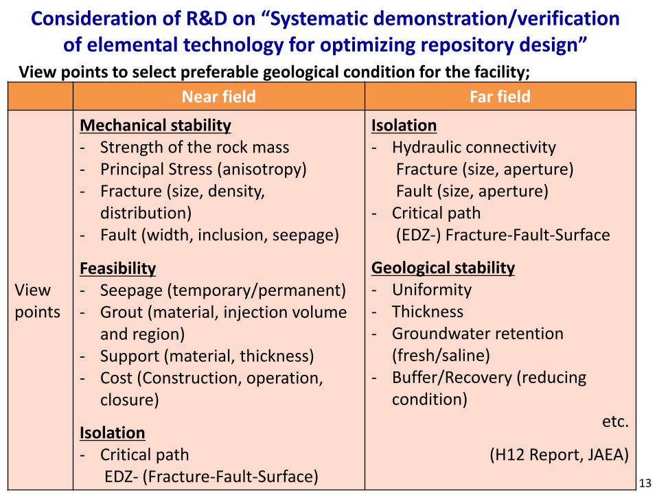
Near field Far field
View points
Mechanical stability- Strength of the rock mass- Principal Stress (anisotropy)- Fracture (size, density,
distribution)- Fault (width, inclusion, seepage)
Feasibility- Seepage (temporary/permanent)- Grout (material, injection volume
and region)- Support (material, thickness)- Cost (Construction, operation,
closure)
Isolation- Critical path
EDZ- (Fracture-Fault-Surface)
Isolation- Hydraulic connectivity
Fracture (size, aperture)Fault (size, aperture)
- Critical path(EDZ-) Fracture-Fault-Surface
Geological stability- Uniformity- Thickness- Groundwater retention
(fresh/saline)- Buffer/Recovery (reducing
condition)etc.
(H12 Report, JAEA)
View points to select preferable geological condition for the facility;
Consideration of R&D on “Systematic demonstration/verification of elemental technology for optimizing repository design”
13
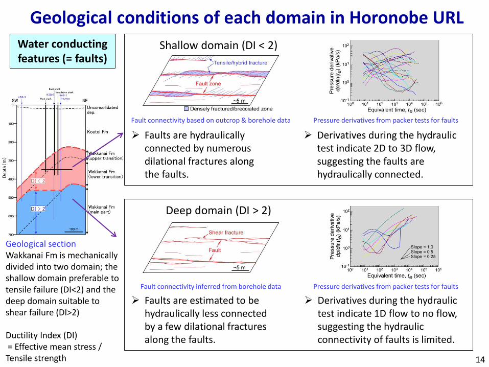
Water conducting features (= faults)
Geological sectionWakkanai Fm is mechanically divided into two domain; the shallow domain preferable to tensile failure (DI<2) and the deep domain suitable to shear failure (DI>2)
Ductility Index (DI)= Effective mean stress / Tensile strength
Geological conditions of each domain in Horonobe URL
Derivatives during the hydraulic test indicate 2D to 3D flow, suggesting the faults are hydraulically connected.
Fault connectivity based on outcrop & borehole data Pressure derivatives from packer tests for faults
Fault connectivity inferred from borehole data
Faults are hydraulically connected by numerous dilational fractures along the faults.
Faults are estimated to be hydraulically less connected by a few dilational fractures along the faults.
Derivatives during the hydraulic test indicate 1D flow to no flow, suggesting the hydraulic connectivity of faults is limited.
Pressure derivatives from packer tests for faults
Shallow domain (DI < 2)
Deep domain (DI > 2)
14
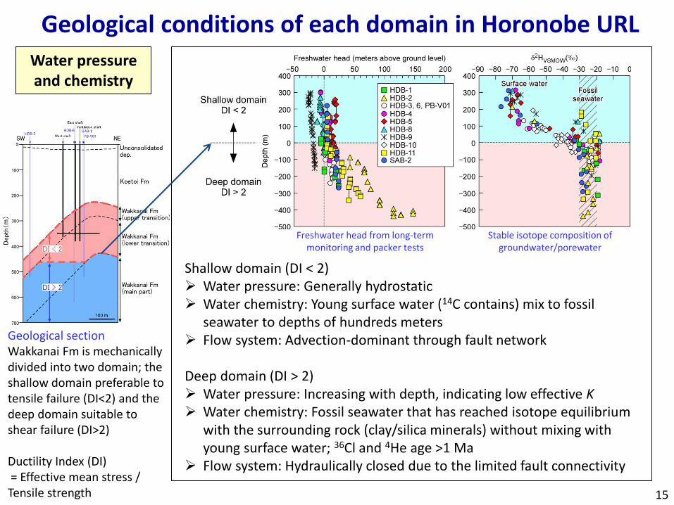
Shallow domain (DI < 2) Water pressure: Generally hydrostatic Water chemistry: Young surface water (14C contains) mix to fossil
seawater to depths of hundreds meters Flow system: Advection-dominant through fault network
Deep domain (DI > 2) Water pressure: Increasing with depth, indicating low effective K Water chemistry: Fossil seawater that has reached isotope equilibrium
with the surrounding rock (clay/silica minerals) without mixing with young surface water; 36Cl and 4He age >1 Ma
Flow system: Hydraulically closed due to the limited fault connectivity
Freshwater head from long-term monitoring and packer tests
Stable isotope composition of groundwater/porewater
Water pressure and chemistry
Geological conditions of each domain in Horonobe URL
15
Geological sectionWakkanai Fm is mechanically divided into two domain; the shallow domain preferable to tensile failure (DI<2) and the deep domain suitable to shear failure (DI>2)
Ductility Index (DI)= Effective mean stress / Tensile strength
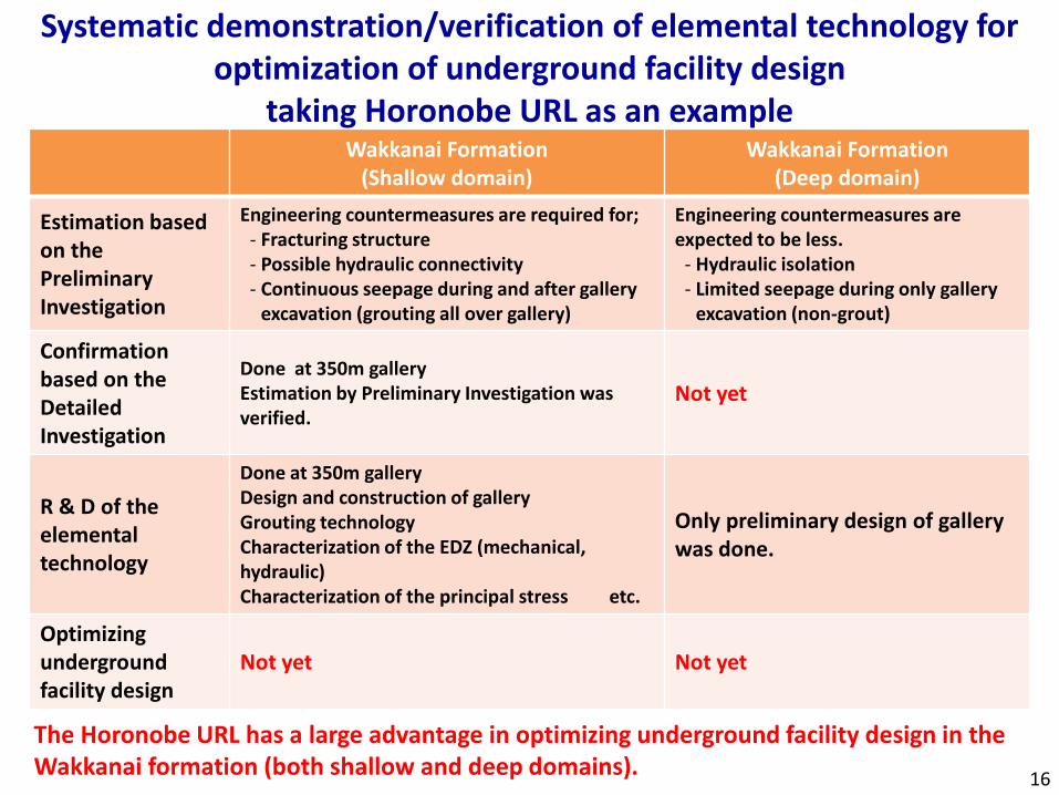
Systematic demonstration/verification of elemental technology for optimization of underground facility design
taking Horonobe URL as an exampleWakkanai Formation
(Shallow domain)Wakkanai Formation
(Deep domain)
Estimation based on the Preliminary Investigation
Engineering countermeasures are required for;- Fracturing structure- Possible hydraulic connectivity- Continuous seepage during and after gallery
excavation (grouting all over gallery)
Engineering countermeasures are expected to be less.
- Hydraulic isolation- Limited seepage during only gallery
excavation (non-grout)
Confirmationbased on the Detailed Investigation
Done at 350m galleryEstimation by Preliminary Investigation was verified.
Not yet
R & D of the elemental technology
Done at 350m galleryDesign and construction of galleryGrouting technologyCharacterization of the EDZ (mechanical, hydraulic)Characterization of the principal stress etc.
Only preliminary design of gallery was done.
Optimizing undergroundfacility design
Not yet Not yet
The Horonobe URL has a large advantage in optimizing underground facility design in the Wakkanai formation (both shallow and deep domains).
16
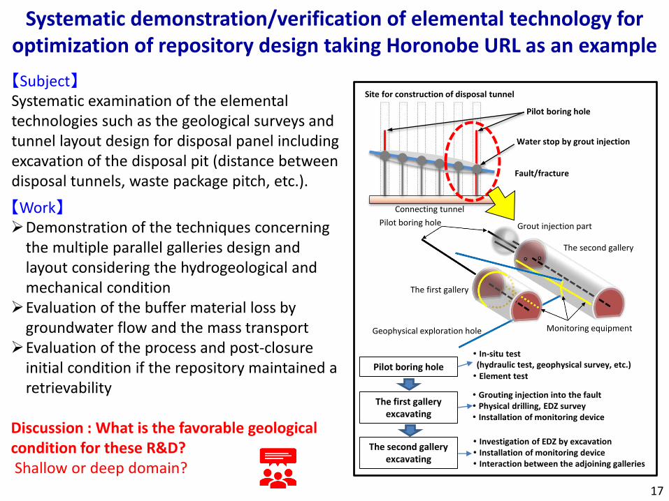
【Subject】Systematic examination of the elemental technologies such as the geological surveys and tunnel layout design for disposal panel including excavation of the disposal pit (distance between disposal tunnels, waste package pitch, etc.).
【Work】Demonstration of the techniques concerning
the multiple parallel galleries design and layout considering the hydrogeological and mechanical condition
Evaluation of the buffer material loss by groundwater flow and the mass transport
Evaluation of the process and post-closure initial condition if the repository maintained a retrievability
Discussion : What is the favorable geological condition for these R&D? Shallow or deep domain?
17
Pilot boring hole
・ In-situ test (hydraulic test, geophysical survey, etc.)・ Element test
The second galleryexcavating
The first galleryexcavating
・ Grouting injection into the fault・ Physical drilling, EDZ survey・ Installation of monitoring device
・ Investigation of EDZ by excavation・ Installation of monitoring device・ Interaction between the adjoining galleries
Site for construction of disposal tunnel
Water stop by grout injection
Pilot boring hole
Connecting tunnel
Grout injection part
Geophysical exploration hole Monitoring equipment
Pilot boring hole
The first gallery
The second gallery
Fault/fracture
Systematic demonstration/verification of elemental technology for optimization of repository design taking Horonobe URL as an example
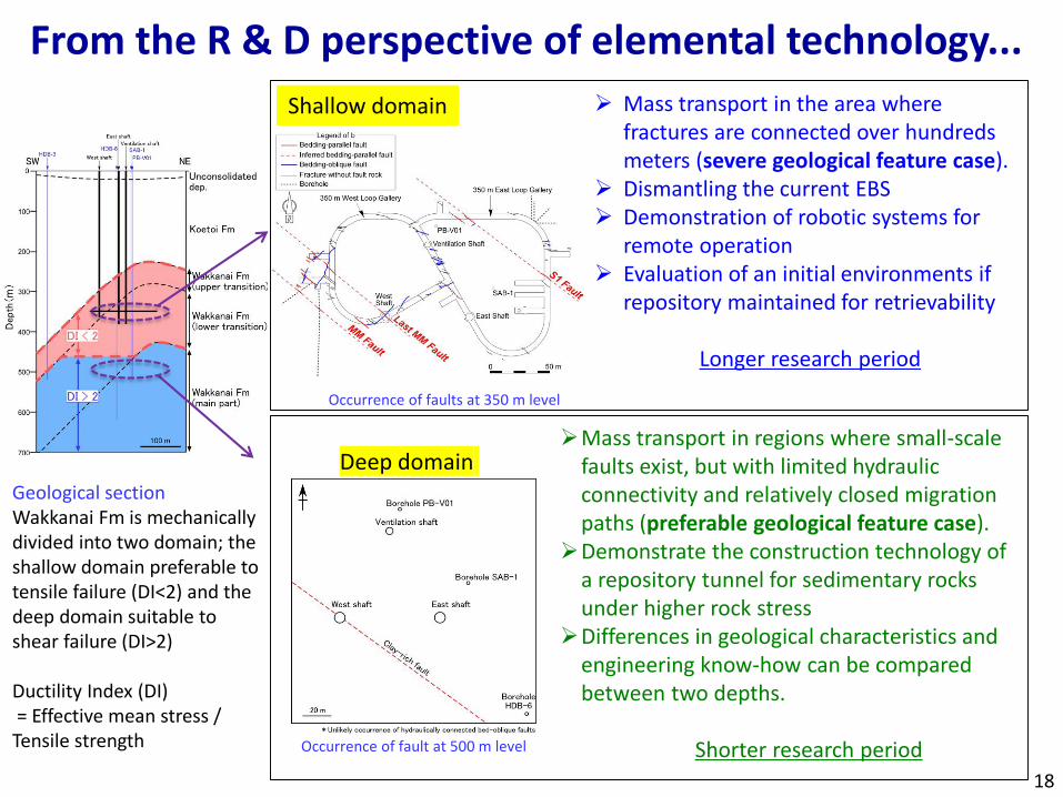
Mass transport in the area where fractures are connected over hundreds meters (severe geological feature case).
Dismantling the current EBS Demonstration of robotic systems for
remote operation Evaluation of an initial environments if
repository maintained for retrievability
Longer research period
Mass transport in regions where small-scale faults exist, but with limited hydraulic connectivity and relatively closed migration paths (preferable geological feature case).
Demonstrate the construction technology of a repository tunnel for sedimentary rocks under higher rock stress
Differences in geological characteristics and engineering know-how can be compared between two depths.
Shorter research period
From the R & D perspective of elemental technology...
Occurrence of faults at 350 m level
Occurrence of fault at 500 m level
Shallow domain
Deep domain
18
Geological sectionWakkanai Fm is mechanically divided into two domain; the shallow domain preferable to tensile failure (DI<2) and the deep domain suitable to shear failure (DI>2)
Ductility Index (DI)= Effective mean stress / Tensile strength
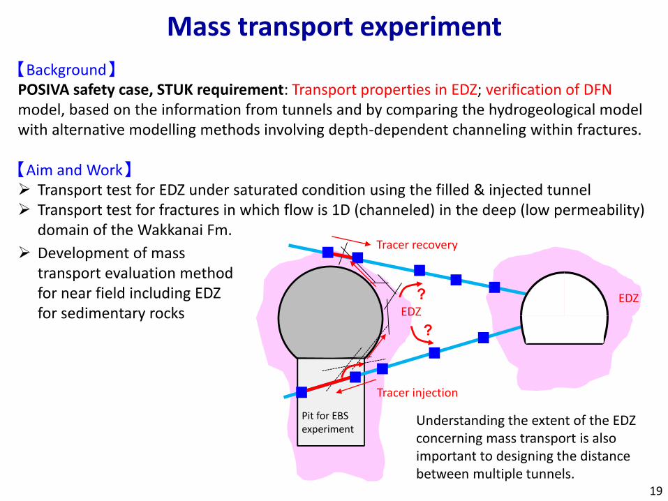
【Background】POSIVA safety case, STUK requirement: Transport properties in EDZ; verification of DFN model, based on the information from tunnels and by comparing the hydrogeological model with alternative modelling methods involving depth-dependent channeling within fractures.
【Aim and Work】 Transport test for EDZ under saturated condition using the filled & injected tunnel Transport test for fractures in which flow is 1D (channeled) in the deep (low permeability)
domain of the Wakkanai Fm.
Understanding the extent of the EDZ concerning mass transport is also important to designing the distance between multiple tunnels.
EDZ
Tracer injection
Tracer recovery
Pit for EBS experiment
?
?
EDZ
Mass transport experiment
19
Development of mass transport evaluation method for near field including EDZ for sedimentary rocks
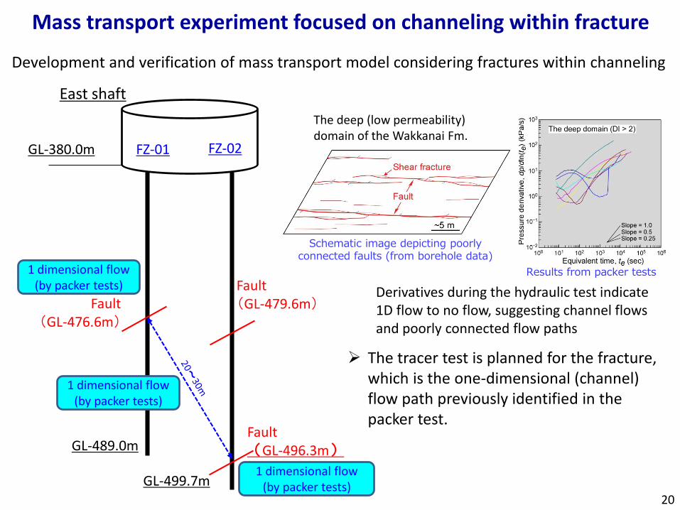
Mass transport experiment focused on channeling within fracture
The tracer test is planned for the fracture, which is the one-dimensional (channel) flow path previously identified in the packer test.
FZ-01 FZ-02GL-380.0m
East shaft
GL-489.0m
GL-499.7m
Fault(GL-476.6m)
Fault(GL-496.3m)
Fault(GL-479.6m)
1 dimensional flow(by packer tests)
1 dimensional flow(by packer tests)
1 dimensional flow(by packer tests)
Schematic image depicting poorly connected faults (from borehole data)
Derivatives during the hydraulic test indicate 1D flow to no flow, suggesting channel flows and poorly connected flow paths
Results from packer tests
The deep (low permeability) domain of the Wakkanai Fm.
20
Development and verification of mass transport model considering fractures within channeling
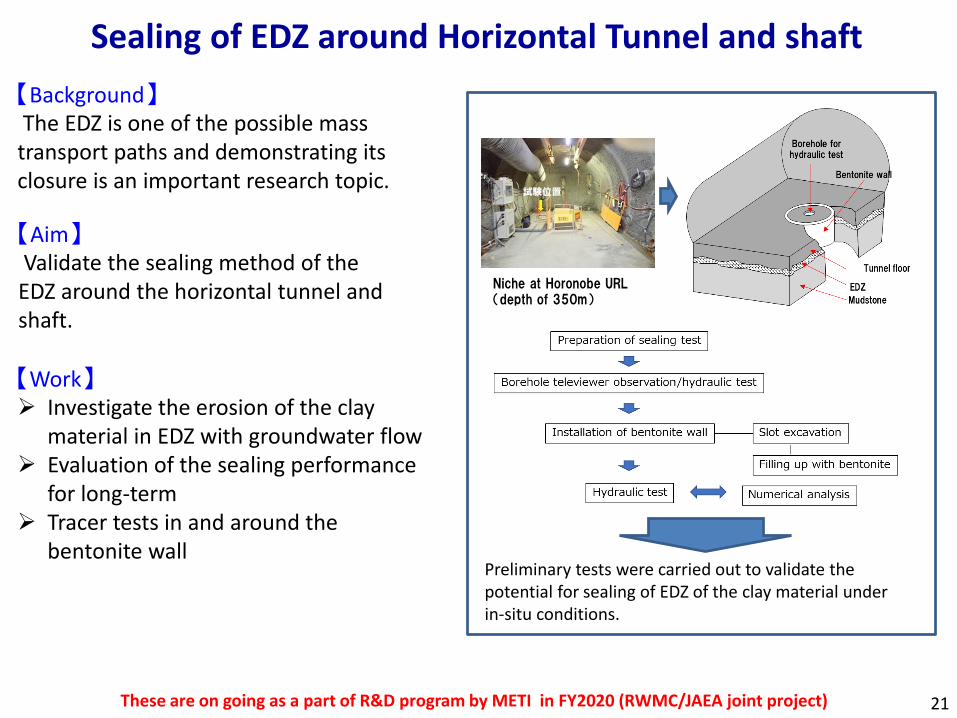
【Aim】Validate the sealing method of the
EDZ around the horizontal tunnel and shaft.
【Work】 Investigate the erosion of the clay
material in EDZ with groundwater flow Evaluation of the sealing performance
for long-term Tracer tests in and around the
bentonite wallPreliminary tests were carried out to validate the potential for sealing of EDZ of the clay material under in-situ conditions.
Niche at Horonobe URL(depth of 350m)
21
Sealing of EDZ around Horizontal Tunnel and shaft
These are on going as a part of R&D program by METI in FY2020 (RWMC/JAEA joint project)
【Background】The EDZ is one of the possible mass
transport paths and demonstrating its closure is an important research topic.
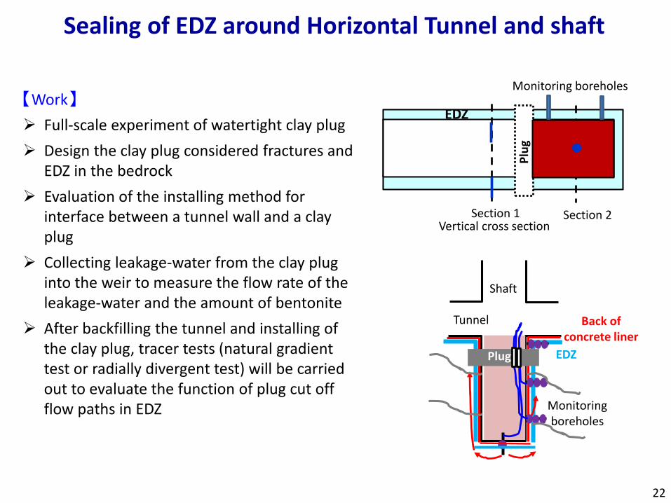
【Work】
Full-scale experiment of watertight clay plug
Design the clay plug considered fractures and EDZ in the bedrock
Evaluation of the installing method for interface between a tunnel wall and a clay plug
Collecting leakage-water from the clay plug into the weir to measure the flow rate of the leakage-water and the amount of bentonite
After backfilling the tunnel and installing of the clay plug, tracer tests (natural gradient test or radially divergent test) will be carried out to evaluate the function of plug cut off flow paths in EDZ
22
プラグ
Section 2Section 1Vertical cross section
EDZ
Sealing of EDZ around Horizontal Tunnel and shaft
Shaft
Tunnel Back of concrete liner
EDZPlug
Monitoring boreholes
Monitoring boreholes
Plu
g
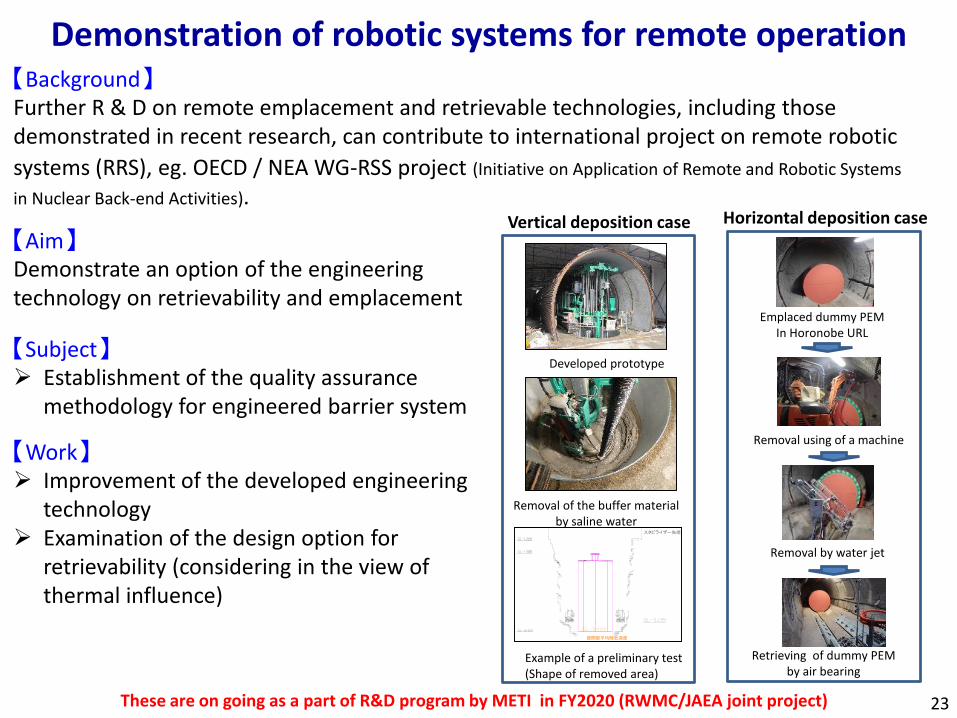
【Aim】Demonstrate an option of the engineering technology on retrievability and emplacement
【Subject】 Establishment of the quality assurance
methodology for engineered barrier system
【Work】 Improvement of the developed engineering
technology Examination of the design option for
retrievability (considering in the view of thermal influence)
Developed prototype
Removal of the buffer material by saline water
Example of a preliminary test(Shape of removed area)
Emplaced dummy PEMIn Horonobe URL
Removal using of a machine
Removal by water jet
Retrieving of dummy PEM by air bearing
Vertical deposition case Horizontal deposition case
These are on going as a part of R&D program by METI in FY2020 (RWMC/JAEA joint project)
Demonstration of robotic systems for remote operation
23
【Background】Further R & D on remote emplacement and retrievable technologies, including those demonstrated in recent research, can contribute to international project on remote robotic
systems (RRS), eg. OECD / NEA WG-RSS project (Initiative on Application of Remote and Robotic Systems
in Nuclear Back-end Activities).
R&D on retrievability and environment
【Aim】 Estimation of the initial condition and relating process if the repository maintained
retrievability Understanding the impact on the safety function of natural barriers due to the existence of
open tunnels during the retrievability period
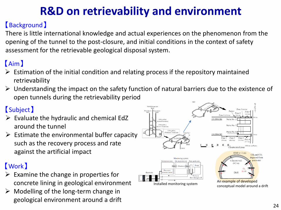
【Subject】 Evaluate the hydraulic and chemical EdZ
around the tunnel Estimate the environmental buffer capacity
such as the recovery process and rate against the artificial impact
Installed monitoring systemAn example of developed conceptual model around a drift
【Work】 Examine the change in properties for
concrete lining in geological environment Modelling of the long-term change in
geological environment around a drift24
【Background】There is little international knowledge and actual experiences on the phenomenon from the opening of the tunnel to the post-closure, and initial conditions in the context of safety assessment for the retrievable geological disposal system.
Domestic/international cooperation
Domestic cooperationTohoku Univ., Univ. of Tokyo, Nagoya Univ. Kyoto Univ., CRIEPI, AIST, RWMC, NIES, etc.
International cooperationDECOVALEX-2023: Development of modelling and simulation technique of T-H-M
process in the EBS (JAEA, KAERI, TaiPower, CAS, BGR)Mont Terri Project: FS-B, Imaging the long-term loss of faulted host rock integrityClay Club: Information exchange regarding clay property, etc.Pacific Rim Partnership: Under consideration to produce a charter for the URL
Working Group (JAEA, CRISO, Sandia, KAERI, TaiPower….)
Horonobe URL has been aiming to become an international research center. The 25th Technical Committee Meeting on JAEA’s URL Projects also recommended to enhance the international cooperation using the Horonobe Center.
Any suggestions?25