Embed Size (px)
DESCRIPTION
laguna tools platninum series tablesaw
Citation preview
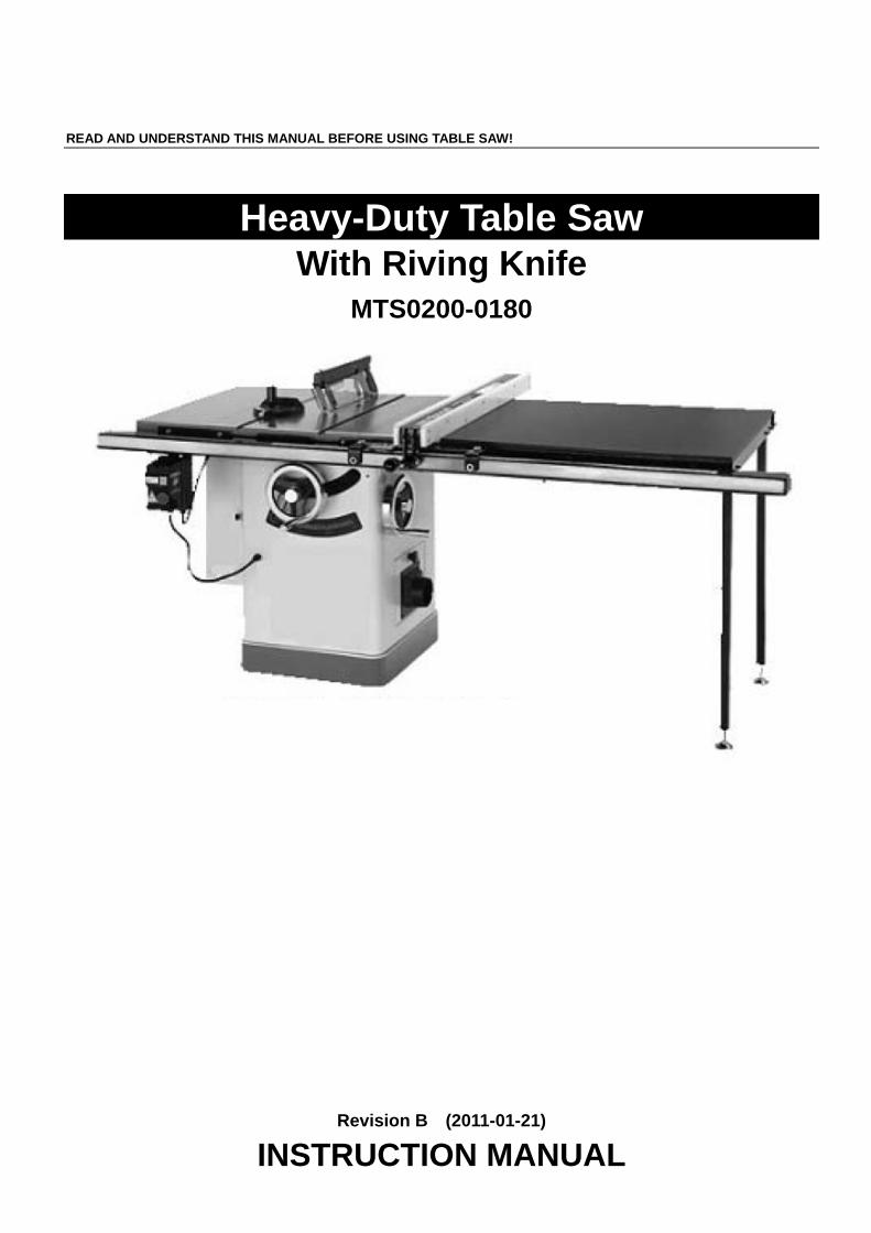
READ AND UNDERSTAND THIS MANUAL BEFORE USING TABLE SAW!
Heavy-Duty Table Saw
With Riving Knife MTS0200-0180
Revision B (2011-01-21)
INSTRUCTION MANUAL

Please save this manual for future reference Heavy-duty table saw 2
PRODUCT SPECIFICATIONS
Item HW110LG-30 HW110LG-50 weight 550Ibs 590Ibs length/width/height 62"×41"×40" 82"×41"×40"
Product Dimensions foot print(length/width) 20"×20"
Electrical: switch magnetic with thermal overload
protection type TEFC capacitor start induction
3HP-220V-1PH 12.8A horsepower/voltage/phase/amps
3HP-220V(380V)-3PH 7.43A/4.8A 3450 RPM/60HZ speed/cycle
2850 RPM/50HZ Moter power transfer Triple V-belt Drive
maximum blade diameter 10" riving knife/spreader thickness 0.1"(2.5mm) required blade body thickness 0.071"-0.094"(1.8-2.4mm) required blade kerf thickness 0.102"-0.126"(2.6-3.2mm) maximum width of Dado 13/16" blade tilt left 0-45° arbor size 5/8“ arbor speed 4300 RPM
blade information arbor bearings sealed and permanently lubricated maximum depth of cut at 90° 3-1/8" maximum depth of cut at 45° 2-3/16" maximum rip to right of blade-standard 30" 50"
cutting capacities maximum rip to left of blade 12" floor to table height 34" main table--length/width/thickness 20"×27"×1-1/2" distance front of table to center of blade 17-1/4"
Table informations distance front of table to blade of maximum cut 12-1/4"
fence information fence size--length/width/height 48"×4-1/8"×2-1/2" miter gauge information miter gauge slot type T-slot
miter gauge slot type-- width/height 3/4" ×3/8"
other information paint power coated dust port size 4"
NOTICE: Shipping Dimensions Unlisted,please contact with us for order;
Please save this manual for future reference Heavy-duty table saw 3
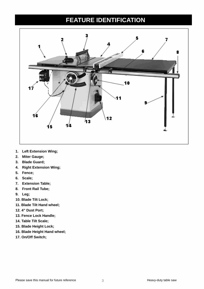
FEATURE IDENTIFICATION
1. Left Extension Wing; 2. Miter Gauge; 3. Blade Guard; 4. Right Extension Wing; 5. Fence; 6. Scale; 7. Extension Table; 8. Front Rail Tube; 9. Leg; 10. Blade Tilt Lock; 11. Blade Tilt Hand wheel; 12. 4” Dust Port; 13. Fence Lock Handle; 14. Table Tilt Scale; 15. Blade Height Lock; 16. Blade Height Hand wheel; 17. On/Off Switch;
Please save this manual for future reference Heavy-duty table saw 4
WARRANTY INFORMATION LIMITED WARRANTY
One year PROOF OF PURCHASE
Please keep your dated proof of purchase for warranty and servicing purposes REPLACEMENT PARTS
About replacement parts, Please use the 10 digit part numbers listed in this manual for all part orders where applicable. LIMITED TOOL WARRANTY
we makes every effort to ensure that this product meets high quality and durability standards. we warrants to the original retail consumer a 1-year limited warranty as of the date the product was purchased at retail and that each product is free from defects in materials. Warranty does not apply to defects due directly or indirectly to misuse, abuse, normal wear and tear, negligence or accidents, repairs done by an unauthorized service center, alterations and lack of maintenance. we shall in no event be liable for death, injuries to persons or property or for incidental, special or consequential damages arising from the use of our products.
To take advantage of this limited warranty, return the product at your expense together with your dated proof of purshase to us ,we will either repair or replace the product if any part or parts covered under this warranty which examination proves to be defective in workmanship or material during the warranty period.
SAFETY INSTRUCTION GENERALSAFETYINSTRUCTIONS FOR POWER TOOLS 1. KNOW YOUR TOOL
Read and understand the owners manual and labels affixed to the tool. Learn its application and limitations as well as its specific potential hazards. 2.GROUND THE TOOL.
This tool is equipped with an approved 3-conductor cord and a3-prong grounding type plug to fit the proper grounding type receptacle. The green conductor in the cord is the grounding wire. NEVER connect the green wire to a live terminal. 3. KEEPGUARDS IN PLACE.
Keep in good working order, properly adjusted and aligned. 4. REMOVE ADJUSTING KEYS AND WRENCHES.
Form habit of checking to see that keys and adjusting wrenches are removed from tool before turning it on. 5. KEEPWORK AREA CLEAN.
Cluttered areas and benches invite accidents. Make sure the floor is clean and not slippery due to wax and sawdust build-up. 6. AVOID DANGEROUS ENVIRONMENT.
Don’t use power tools in damp or wet locations or expose them to rain. Keep work area well lit and provide adequate surroun-ding work space 7. KEEPCHILDREN AWAY.
All visitors should be kept a safe distance from work area. 8. MAKE WORKSHOPCHILD-PROOF.
With padlocks, master switches or by removing starter keys. 9. USE PROPER SPEED.
A tool will do a better and safer job when operated at the proper speed. 10. USE RIGHT TOOL.
Don’t force the tool or the attachment to do a job for which it was not designed. 11. WEAR PROPER APPAREL.
Do not wear loose clothing, gloves, neckties or jewelry (rings, watch) because they could get caught in moving parts. Non-slip footwear is recommended. Wear protective hair covering to contain long hair. Roll up long sleeves above the elbows. 12. ALWAYS WEAR SAFETY GLASSES.
Always wear safety glasses. Everyday eyeglasses only have impact resistant lenses, thet are NOT safety glasses. Also use a face or dust mask if cutting operation is dusty. 13. DON’T OVERREACH.
Keep proper footing and balance at all times. 14. MAINTAIN TOOL WITH CARE.
Keep tools sharp and clean for best and safest performance. Follow instructions for lubricating and changing
Please save this manual for future reference Heavy-duty table saw 5
accessories. 15. DISCONNECT TOOLS.
Before servicing, when changing accessories or attachments. 16. AVOID ACCIDENTAL STARTING.
Make sure the switch is in the ‘’OFF’ ’position before plugging in. 17. USE RECOMMENDED ACCESSORIES.
Consult the manual for recommended accessories. Follow the instructions that accompany the accessories. The use of improper accessories may cause hazards. 18. NEVER STAND ON TOOL.
Serious injury could occur if the tool tips over .Do not store materials such that it is necessary to stand on the tool to reach them. 19. CHECK DAMAGED PARTS.
Before further use of the tool, a guard or other parts that are damaged should be carefully checked to ensure that they will operate properly and perform their intended function. Check for alignment of moving parts, breakage of parts, mounting, and any other conditions that may affect its operation. A guard or other parts that are damaged should be properly repaired or replaced. 20. NEVER LEAVE MACHINE RUNNING UNATTENDED.
Turn power ‘’OFF’’. Don’t leave any tool running until it comes to a complete stop.
SPECIFIC SAFETYINSTRUCTIONS FOR TABLE SAWS 1. ALWAYS USE A GUARD.
Always use a guard, splitter and anti-kickback fingers on all “thru-sawing” operations. Thru-sawing operations are those when the blade cuts completely through the work piece as in ripping or crosscutting. 2. ALWAYS HOLD THE WORK.
Always hold the work firmly against the miter gauge or fence. 3. ALWAYS USE A PUSHSTICK.
For ripping narrow stock. Refer to ripping applications in instruction manual where push sticks are covered in detail. 4.NEVER.
Never perform any operations “free-hand” which means using your hands to support or guide the work piece. Always use either the fence or the miter gauge to position and guide the work piece. 5.NEVER.
Never stand or have any part of your body in line with the path of the saw blade. 6.NEVER REACH BEHIND.
Never reach behind or over the cutting tool with either hand for any reason. 7. MOVE THE RIP FENCE.
Move the rip fence out of the way when crosscutting. 8. WHEN CUTTING MOULDINGS.
Never run the stock between the fence and the moulding cutter-head. Refer to moulding applications in the accessory manual for details. 9. DIRECTION OF FEED.
Feed work into the blade against the direction of rotation. 10. NEVER.
Never use the fence as a cut-off gauge when you are cross-cutting. 11. NEVER.
Never attempt to free a stalled saw blade without first turning the saw OFF. 12. PROVIDE ADEQUATE SUPPORT.
To the rear and sides of the table saw for wide or long work pieces. 13. AVOID KICKBACKS.
Avoid kickbacks (work thrown back towards you) by keeping the blade sharp, by keeping the rip fence parallel to the saw blade, by keeping the splitter and anti-kickback fingers and guard in place and operating, by not releasing work before it is pushed all the way past the saw blade, and by not ripping work that is twisted or warped or does not have a straight edge to guide along the fence. 14. AVOID AWKWARD OPERATIONS.
Avoid awkward operations and hand positions where a sudden slip could cause your hand to move into the spinning blade.
Please save this manual for future reference Heavy-duty table saw 6
ELECTRICAL REQUIREMENTS POWER SUPPLY:
BEFORE YOU CONNECT THE MACHINE TO THE POWER SOURCE, YOU MUST KNOW THE PRE-WIRED VOLTAGE OF YOUR MACHINE, AND KNOW THE POWER SUPPLY.
If you are unsure, consult a qualified electrician. THIS CABINET SAW CAME PRE-WIRED : 220V/1PH: PRE-WIRED FOR 220V/1PH Cord:----------3Wire 220V/3PH: PRE-WIRED FOR 220V/3PH Cord:----------4Wire 380V/3PH: PRE-WIRED FOR 380V/3PH Cord:----------5Wire You can change the connections from 220V/3PH to 380V/3PH.or from 380V/3PH to 220V/3PH, If you are unsure, you must consult a qualified electrician. GROUNDING; WARNING:IF OUTLET IS NOT PROPERLY GROUNDED, THIS CABINET SAW CAN CAUSE ELECTRICAL SHOCK, PARTICULARLY WHEN USED IN DAMP LOCATIONS. TO AVOID SHOCK OR FIRE,IF THE POWER CORD IS WORN OR DAMAGED IN ANY WAY, HAVE IT REPLACED IMMEDIATELY.
Not all outlets are properly grounded. If you are not sure if your outlet is properly grounded, have it checked by a qualified electrician.
This cabinet saw must be grounded, if it should malfunction or breakdown, grounding provides a path of least resistance for electric current, which reduces the risk of electric shock. EXTENSION CORDS:
Makes sure the extension cord rating is suitable for the amperage listed on the machine's motor plate. An undersize cord will cause a drop in line voltage resulting in loss of power and overheating. Fig shows the correct size cord to use based on cord length and motor plate amp rating. If in doubt, use the next heavier gauge. The smaller the gauge number, the heavier the cord.
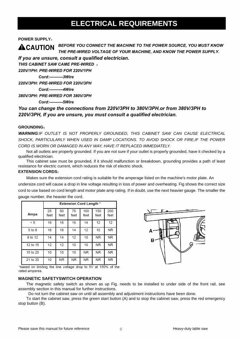
MAGNETIC SAFETYSWITCH OPERATION The magnetic safety switch as shown as up Fig. needs to be installed to under side of the front rail, see
assembly section in this manual for further instructions. Do not turn the cabinet saw on until all assembly and adjustment instructions have been done.
To start the cabinet saw, press the green start button (A) and to stop the cabinet saw, press the red emergency stop button (B).
Please save this manual for future reference Heavy-duty table saw 7
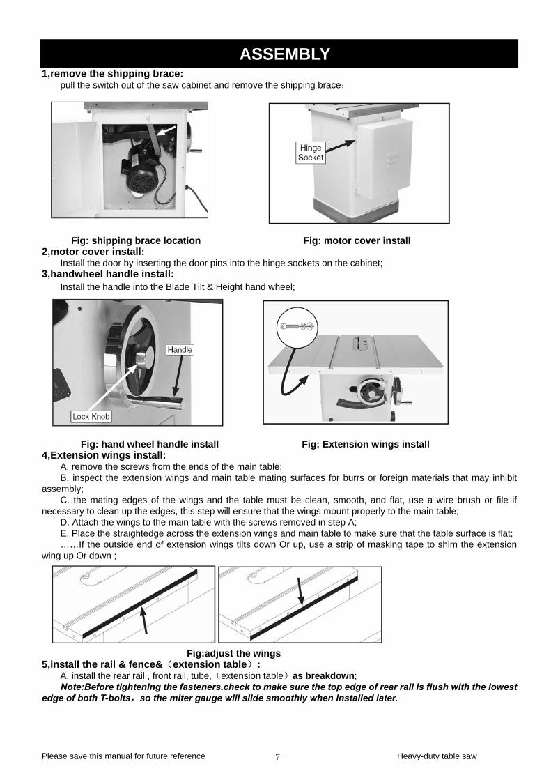
ASSEMBLY 1,remove the shipping brace:
pull the switch out of the saw cabinet and remove the shipping brace;
Fig: shipping brace location Fig: motor cover install
2,motor cover install: Install the door by inserting the door pins into the hinge sockets on the cabinet;
3,handwheel handle install: Install the handle into the Blade Tilt & Height hand wheel;
Fig: hand wheel handle install Fig: Extension wings install 4,Extension wings install:
A. remove the screws from the ends of the main table; B. inspect the extension wings and main table mating surfaces for burrs or foreign materials that may inhibit
assembly; C. the mating edges of the wings and the table must be clean, smooth, and flat, use a wire brush or file if
necessary to clean up the edges, this step will ensure that the wings mount properly to the main table; D. Attach the wings to the main table with the screws removed in step A; E. Place the straightedge across the extension wings and main table to make sure that the table surface is flat; ……If the outside end of extension wings tilts down Or up, use a strip of masking tape to shim the extension
wing up Or down ;
Fig:adjust the wings 5,install the rail & fence&(extension table):
A. install the rear rail , front rail, tube,(extension table)as breakdown; Note:Before tightening the fasteners,check to make sure the top edge of rear rail is flush with the lowest
edge of both T-bolts,so the miter gauge will slide smoothly when installed later.
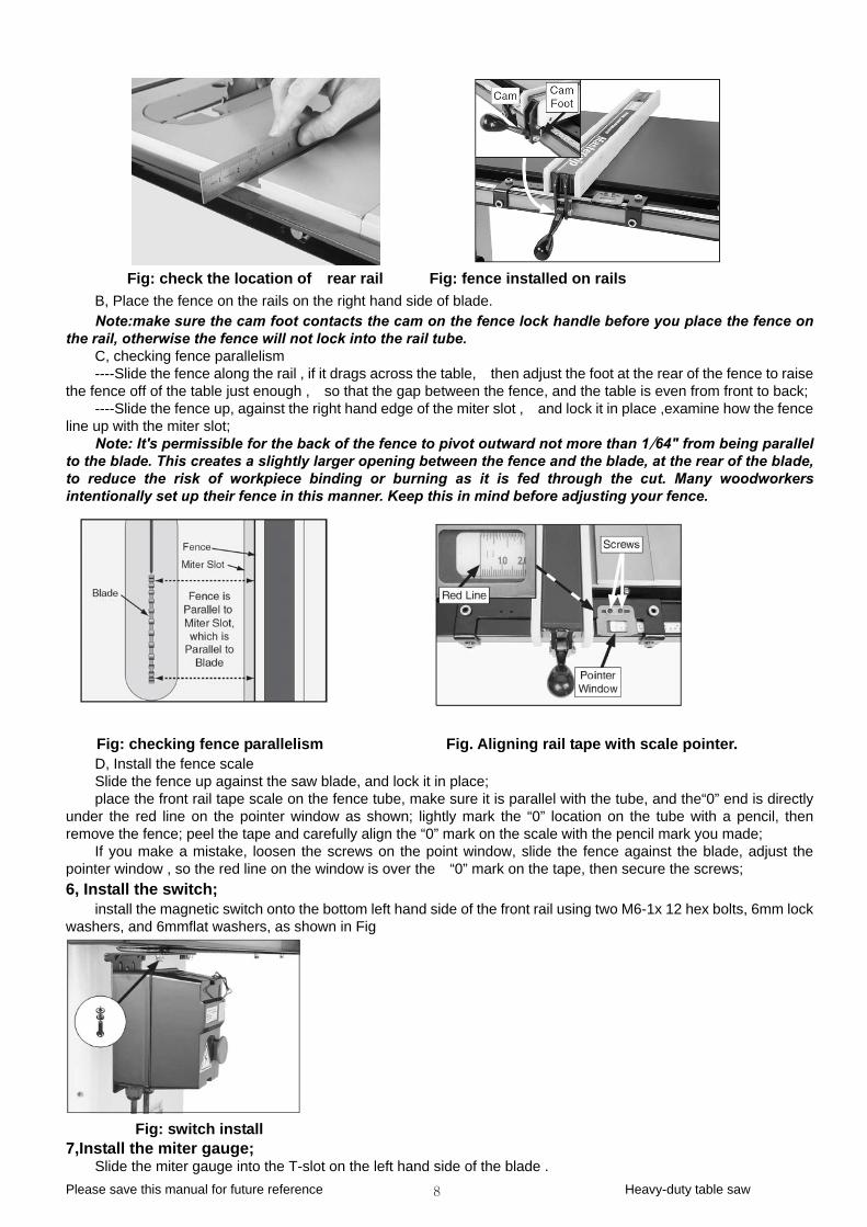
Please save this manual for future reference Heavy-duty table saw 8
Fig: check the location of rear rail Fig: fence installed on rails B, Place the fence on the rails on the right hand side of blade. Note:make sure the cam foot contacts the cam on the fence lock handle before you place the fence on
the rail, otherwise the fence will not lock into the rail tube. C, checking fence parallelism ----Slide the fence along the rail , if it drags across the table, then adjust the foot at the rear of the fence to raise
the fence off of the table just enough , so that the gap between the fence, and the table is even from front to back; ----Slide the fence up, against the right hand edge of the miter slot , and lock it in place ,examine how the fence
line up with the miter slot; Note: It's permissible for the back of the fence to pivot outward not more than 1⁄64" from being parallel
to the blade. This creates a slightly larger opening between the fence and the blade, at the rear of the blade, to reduce the risk of workpiece binding or burning as it is fed through the cut. Many woodworkers intentionally set up their fence in this manner. Keep this in mind before adjusting your fence.
Fig: checking fence parallelism Fig. Aligning rail tape with scale pointer. D, Install the fence scale Slide the fence up against the saw blade, and lock it in place; place the front rail tape scale on the fence tube, make sure it is parallel with the tube, and the“0” end is directly
under the red line on the pointer window as shown; lightly mark the “0” location on the tube with a pencil, then remove the fence; peel the tape and carefully align the “0” mark on the scale with the pencil mark you made;
If you make a mistake, loosen the screws on the point window, slide the fence against the blade, adjust the pointer window , so the red line on the window is over the “0” mark on the tape, then secure the screws; 6, Install the switch;
install the magnetic switch onto the bottom left hand side of the front rail using two M6-1x 12 hex bolts, 6mm lock washers, and 6mmflat washers, as shown in Fig
Fig: switch install
7,Install the miter gauge; Slide the miter gauge into the T-slot on the left hand side of the blade .
Please save this manual for future reference Heavy-duty table saw 9
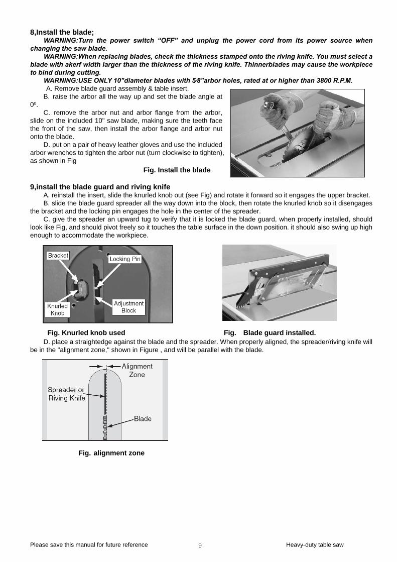
8,Install the blade; WARNING:Turn the power switch “OFF” and unplug the power cord from its power source when
changing the saw blade. WARNING:When replacing blades, check the thickness stamped onto the riving knife. You must select a
blade with akerf width larger than the thickness of the riving knife. Thinnerblades may cause the workpiece to bind during cutting.
WARNING:USE ONLY 10″diameter blades with 5⁄8″arbor holes, rated at or higher than 3800 R.P.M. A. Remove blade guard assembly & table insert.
B. raise the arbor all the way up and set the blade angle at 0º.
C. remove the arbor nut and arbor flange from the arbor, slide on the included 10" saw blade, making sure the teeth face the front of the saw, then install the arbor flange and arbor nut onto the blade.
D. put on a pair of heavy leather gloves and use the included arbor wrenches to tighten the arbor nut (turn clockwise to tighten), as shown in Fig
Fig. Install the blade 9,install the blade guard and riving knife
A. reinstall the insert, slide the knurled knob out (see Fig) and rotate it forward so it engages the upper bracket. B. slide the blade guard spreader all the way down into the block, then rotate the knurled knob so it disengages
the bracket and the locking pin engages the hole in the center of the spreader. C. give the spreader an upward tug to verify that it is locked the blade guard, when properly installed, should
look like Fig, and should pivot freely so it touches the table surface in the down position. it should also swing up high enough to accommodate the workpiece.
Fig. Knurled knob used Fig. Blade guard installed. D. place a straightedge against the blade and the spreader. When properly aligned, the spreader/riving knife will
be in the "alignment zone," shown in Figure , and will be parallel with the blade.
Fig. alignment zone
Please save this manual for future reference Heavy-duty table saw 10
ADJUSTMENTS 1,BLADE RAISING AND TILTING MECHANISM;
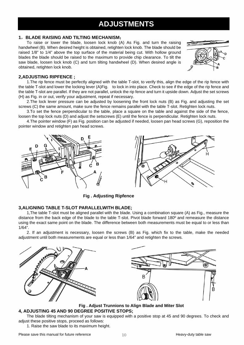
To raise or lower the blade, loosen lock knob (A) As Fig. and turn the raising handwheel (B). When desired height is obtained, retighten lock knob. The blade should be raised 1/8” to 1/4” above the top surface of the material being cut. With hollow ground blades the blade should be raised to the maximum to provide chip clearance. To tilt the saw blade, loosen lock knob (C) and turn tilting handwheel (D). When desired angle is obtained, retighten lock knob. 2,ADJUSTING RIPFENCE ;
1.The rip fence must be perfectly aligned with the table T-slot, to verify this, align the edge of the rip fence with the table T-slot and lower the locking lever (A)Fig. to lock in into place. Check to see if the edge of the rip fence and the table T-slot are parallel. If they are not parallel, unlock the rip fence and turn it upside down. Adjust the set screws (H) as Fig. in or out, verify your adjustment, repeat if necessary.
2.The lock lever pressure can be adjusted by loosening the front lock nuts (B) as Fig. and adjusting the set screws (C) the same amount, make sure the fence remains parallel with the table T-slot. Retighten lock nuts.
3.To set the fence perpendicular to the table, place a square on the table and against the side of the fence, loosen the top lock nuts (D) and adjust the setscrews (E) until the fence is perpendicular. Retighten lock nuts.
4.The pointer window (F) as Fig. position can be adjusted if needed, loosen pan head screws (G), reposition the pointer window and retighten pan head screws.
Fig . Adjusting Ripfence 3,ALIGNING TABLE T-SLOT PARALLELWITH BLADE;
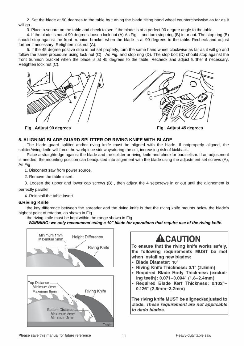
1,The table T-slot must be aligned parallel with the blade. Using a combination square (A) as Fig., measure the distance from the back edge of the blade to the table T-slot. Pivot blade forward 180º and remeasure the distance using the exact same point on the blade. The difference between both measurements must be equal to or less than 1/64”.
2. If an adjustment is necessary, loosen the screws (B) as Fig. which fix to the table, make the needed adjustment until both measurements are equal or less than 1/64” and retighten the screws.
Fig . Adjust Trunnions to Align Blade and Miter Slot 4, ADJUSTING 45 AND 90 DEGREE POSITIVE STOPS;
The blade tilting mechanism of your saw is equipped with a positive stop at 45 and 90 degrees. To check and adjust these positive stops, proceed as follows:
1. Raise the saw blade to its maximum height.
Please save this manual for future reference Heavy-duty table saw 11
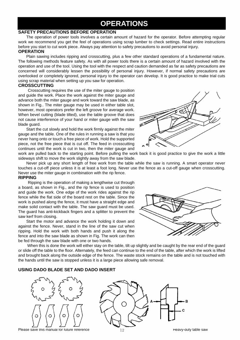
2. Set the blade at 90 degrees to the table by turning the blade tilting hand wheel counterclockwise as far as it will go.
3. Place a square on the table and check to see if the blade is at a perfect 90 degree angle to the table. 4. If the blade is not at 90 degrees loosen lock nut (A) As Fig. and turn stop ring (B) in or out. The stop ring (B)
should stop against the front trunnion bracket when the blade is at 90 degrees to the table. Recheck and adjust further if necessary. Retighten lock nut (A).
5. If the 45 degree postive stop is not set properly, turn the same hand wheel clockwise as far as it will go and follow the same procedure using lock nut (C) As Fig. and stop ring (D). The stop bolt (D) should stop against the front trunnion bracket when the blade is at 45 degrees to the table. Recheck and adjust further if necessary. Retighten lock nut (C).
Fig . Adjust 90 degrees Fig . Adjust 45 degrees
5. ALIGNING BLADE GUARD SPLITTER OR RIVING KNIFE WITH BLADE The blade guard splitter and/or riving knife must be aligned with the blade. If notproperly aligned, the
splitter/riving knife will force the workpiece sidewaysduring the cut, increasing risk of kickback. Place a straightedge against the blade and the splitter or riving knife and checkfor parallelism. If an adjustment
is needed, the mounting position can beadjusted into alignment with the blade using the adjustment set screws (A), As Fig
1. Disconect saw from power source. 2. Remove the table insert. 3. Loosen the upper and lower cap screws (B) , then adjust the 4 setscrews in or out until the alignement is
perfectly parallel. 4. Reinstall the table insert.
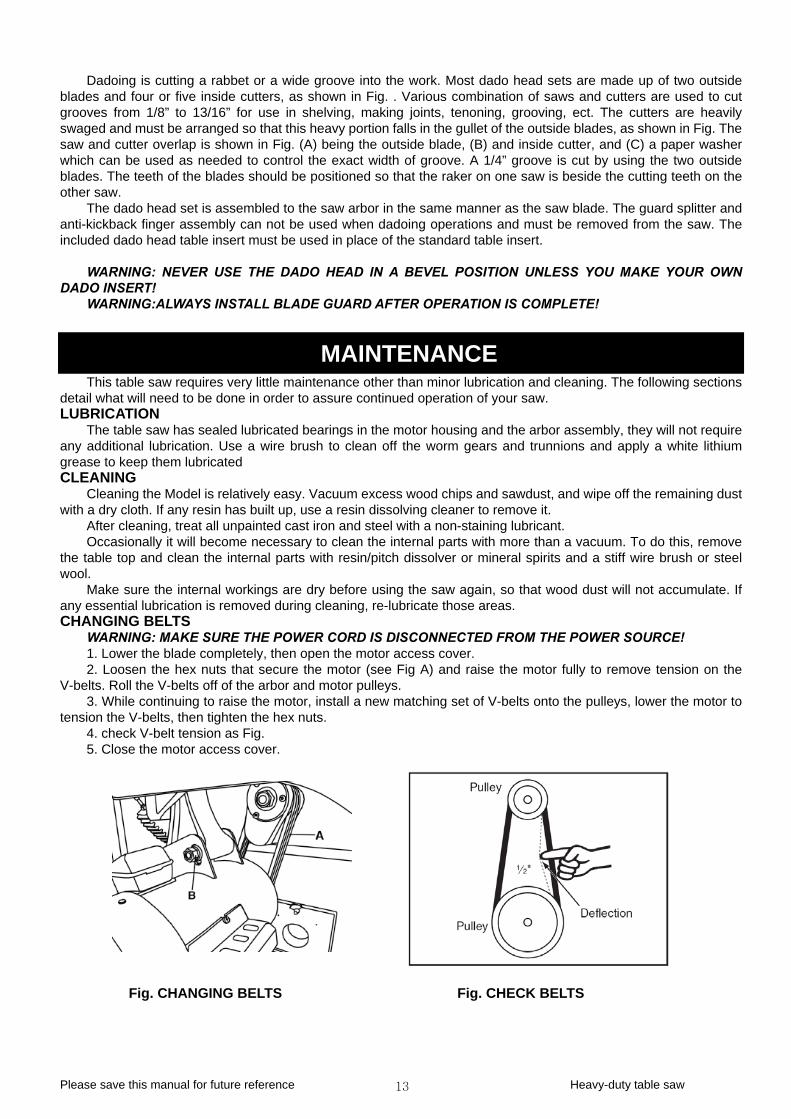
6.Riving Knife the key difference between the spreader and the riving knife is that the riving knife mounts below the blade's
highest point of rotation, as shown in Fig. the riving knife must be kept within the range shown in Fig WARNING: we only recommend using a 10" blade for operations that require use of the riving knife.
Please save this manual for future reference Heavy-duty table saw 12
OPERATIONS SAFETY PRECAUTIONS BEFORE OPERATION
The operation of power tools involves a certain amount of hazard for the operator. Before attempting regular work we recommend you get the feel of operations using scrap lumber to check settings. Read entire instructions before you start to cut work piece. Always pay attention to safety precautions to avoid personal injury. OPERATION
Plain sawing includes ripping and crosscutting, plus a few other standard operations of a fundamental nature. The following methods feature safety. As with all power tools there is a certain amount of hazard involved with the operation and use of the tool. Using the tool with the respect and caution demanded as far as safety precautions are concerned will considerably lessen the possibility of personal injury. However, if normal safety precautions are overlooked or completely ignored, personal injury to the operator can de ake trial cuts using scrap material when setting up you saw for operation.
rted
hile the saw is running. A smart operator never the fence as a cut-off gauge when crosscutting.
the
d of the table, after which the work is lifted tock remains on the table and is not touched with g safe removal.
velop. It is good practice to m
CROSSCUTTING Crosscutting requires the use of the miter gauge to position
and guide the work. Place the work against the miter gauge and advance both the miter gauge and work toward the saw blade, as shown in Fig.. The miter gauge may be used in either table slot, however, most operators prefer the left groove for average work. When bevel cutting (blade tilted), use the table groove that does not cause interference of your hand or miter gauge with the saw blade guard.
Start the cut slowly and hold the work firmly against the miter gauge and the table. One of the rules in running a saw is that you never hang onto or touch a free piece of work. Hold the suppopiece, not the free piece that is cut off. The feed in crosscutting continues until the work is cut in two, then the miter gauge and work are pulled back to the starting point. Before pulling the worksideways shift to move the work slightly away from the saw blade.
Never pick up any short length of free work from the table wtouches a cut-off piece unless it is at least a foot long. Never useNever use the miter gauge in combination with the rip fence. RIPPING
Ripping is
back it is good practice to give the work a little
the operation of making a lengthwise cut through a board, as shown in Fig., and the rip fence is used to position and guide the work. One edge of the work rides against the rip fence while the flat side of the board rest on the table. Since the work is pushed along the fence, it must have a straight edge and make solid contact with the table. The saw guard must be used. The guard has anti-kickback fingers and a splitter to prevent the saw kerf from closing.
Start the motor and advance the work holding it down and against the fence. Never, stand in the line of the saw cut when ripping. Hold the work with both hands and push it along fence and into the saw blade as shown in Fig. The work can then be fed through the saw blade with one or two hands.
When this is done the work will either stay on the table, tilt up sor slide off the table to the floor. Alternately, the feed can continue to the enand brought back along the outside edge of the fence. The waste sthe hands until the saw is stopped unless it is a large piece allowin
USING DADO BLADE SET AND DADO INSERT
lightly and be caught by the rear end of the guard
Pleas w 13
Dadoing is cutting a rabbet or a wide groove into the work. Most dado head sets are made up of two outside blades and four or five inside cutters, as shown in Fig. . Various combination of saws and cutters are used to cut grooves from 1/8” to 13/16” for use in shelving, making joints, tenoning, grooving, ect. The cutters are heavily swaged and must be arranged so that this heavy portion falls in the gullet of the outside blades, as shown in Fig. The saw and cutter overlap is shown in Fig. (A) being the outside blade, (B) and inside cutter, and (C) a per washer which can be used as needed to control the exact width of groove. A 1/4” groove is cut by using the two outside blades. The teeth of the blades should be positioned so that the raker on one saw is beside the cutting teeth on the other saw.
The dado head set is assembled to the saw arbor in the same manner as the saw blade. The gua splitter and anti-kickback finger assembly can not be used when dadoing operations and must be removed from the saw. The included dado head table insert must be used in place of the standard table insert.
pa
rd
WARNING: NEVER USE THE DADO HEAD IN A BEVEL POSITION UNLESS YOU MAKE YOUR OWN DADO INSERT!
WARNING:ALWAYS INSTALL BLADE GUARD AFTER OPERATION IS COMPLETE!
MAINTENANCE This table saw requires very little maintenance other than minor lubrication and cleaning. The following sections
deta
or assembly, they will not require any additional lubrication. Use a wire brush to clean off the worm gears and trunnions and apply a white lithium grea
off the remaining dust ith a dry cloth. If any resin has built up, use a resin dissolving cleaner to remove it.
After cleaning, treat all unpainted cast iron and steel with a non-staining lubricant. Occasionally it will become necessary t ore than a vacuum. To do this, remove
the table top and clean the internal parts w spirits and a stiff wire brush or steel woo
ood dust will not accumulate. If cation is removed during cleaning, re-lubricate those areas.
CHA
ly, then open the motor access cover. the hex nuts that secure the motor (see Fig A) and raise the motor fully to remove tension on the
V-be the pulleys, lower the motor to
tens
Fig. CHANGING BELTS Fig. CHECK BELTS
il what will need to be done in order to assure continued operation of your saw. LUBRICATION
The table saw has sealed lubricated bearings in the motor housing and the arb
se to keep them lubricated CLEANING
Cleaning the Model is relatively easy. Vacuum excess wood chips and sawdust, and wipew
o clean the internal parts with mith resin/pitch dissolver or mineral
l. Make sure the internal workings are dry before using the saw again, so that w
any essential lubriNGING BELTS
WARNING: MAKE SURE THE POWER CORD IS DISCONNECTED FROM THE POWER SOURCE! 1. Lower the blade complete2. Loosenlts. Roll the V-belts off of the arbor and motor pulleys. 3. While continuing to raise the motor, install a new matching set of V-belts ontoion the V-belts, then tighten the hex nuts. 4. check V-belt tension as Fig. 5. Close the motor access cover.
e save this manual for future reference Heavy-duty table sa
Please save this manual for future reference Heavy-duty table saw 14
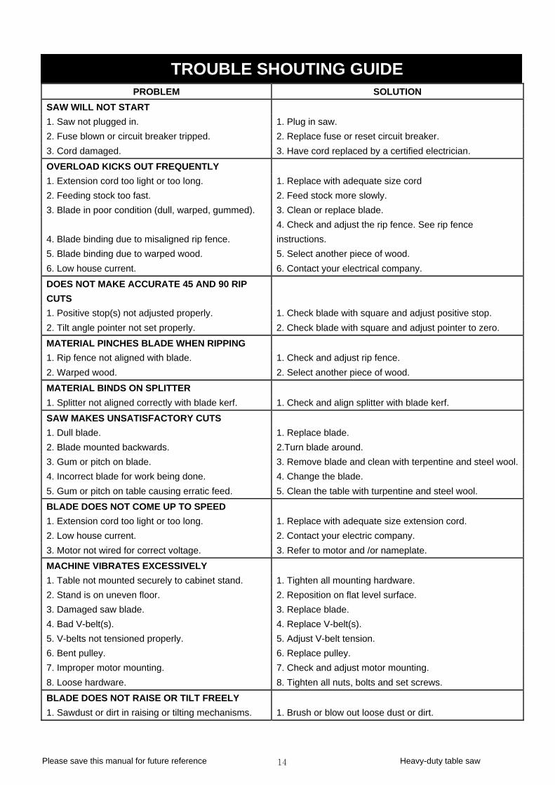
TROUBLE SHOUTING GUIDE PROBLEM SOLUTION
SAW WILL NOT START 1. Saw not plugged in. 1. Plug in saw. 2. Fuse blown or circuit breaker tripped. 2. Replace fuse or reset circuit breaker. 3. Cord damaged. 3. Have cord replaced by a certified electrician.
OVERLOAD KICKS OUT FREQUENTLY 1. Extension cord too light or too long. 1. Replace with adequate size cord 2. Feeding stock too fast. 2. Feed stock more slowly. 3. Blade in poor condition (dull, warped, gummed). 3. Clean or replace blade.
4. Blade binding due to misali4. Check and adjust the rip fence. See rip fence
gned rip fence. instructions. 5. Blade binding due to warped wood. 5. Select another piece of wood. 6. Low house curren 6. Contact your electrict. al company.
DOES NOT MAKE ACCURATE 45 AND 90 RIP CUTS 1. Positive stop(s) not adjusted properly. 1. Check blade with square and adjust positive stop. 2. Tilt angle pointer not set properly. zero. 2. Check blade with square and adjust pointer to
MATERIAL PINCHES BLADE WHEN RIPPING 1. Rip fence not aligned with blade. 1. Check and adjust rip fence. 2. Warped wood. 2. Select another piece of wood.
MATERIAL BINDS ON SPLITTER 1. Splitter not aligned correctly with blade kerf. 1. Check and align splitter with blade kerf.
SAW MAKES UNSATISFACTORY CUTS 1. Dull blade. 1. Replace blade. 2. Blade mounted backwards. 2.Turn blade around. 3. Gum or pitch on blade. 3. Remove blade and clean with terpentine and steel wool.4. Incorrect blade for work being done. 4. Change the blade. 5. Gum or pitch on table causing erratic feed. 5. Clean the table with turpentine and steel wool.
BLADE DOES NOT COME UP TO SPEED 1. Extension cord too light or too long. 1. eplace with adequate size exten R sion cord. 2. Low house current. 2. Contact your electric company. 3. Motor not wired for correct voltage. te. 3. Refer to motor and /or namepla
MACHINE VIBRATES EXCESSIVELY 1. Table not mounted securely to cabinet stand. 1. Tighten all mounting hardware. 2. Stand is on uneven floor. 2. Reposition on flat level surface. 3. Damaged saw blade. 3. Replace blade. 4. Bad V-belt(s). 4. Replace V-belt(s). 5. V-belts not tensioned properly. 5. Adjust V-belt tension. 6. Bent pulley. 6. Replace pulley. 7. Improper motor mounting. 7. Check and adjust motor mounting. 8. Loose hardware. 8. Tighten all nuts, bolts and set screws.
BLADE DOES NOT RAISE OR TILT FREELY 1. Sawdust or dirt in raising or tilting mechanisms. 1. Brush or blow out loose dust or dirt.
15
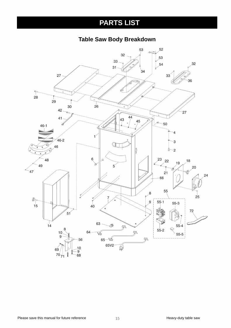
PART
Table Saw Body Breakdown
S LIST
Please save this manual for future reference Heavy-duty table saw

Please save this manual for future reference Heavy-duty table saw 16
Table Saw Body Parts List
REF# DERIPTION QTY REF# DERIPTION QTY 1 CABINET 1 42 HEX BOLT M10-1.5×20 12 CAP SCREW M10-1.25×25 4 43 FLAT WASHER 10MM 13 LOCK WASHER 10MM 4 44 LOCK WASHER 10MM 14 FLAT WASHER 10MM 4 45 HEX NOT M10-1.5 15 ANGLE SCALE 1 46 DUST CLIP 16 STRAIN RELIEF 1 46-1 UPPER BRUSH 17 CABINET PLATE 1 46-2 LOWER BRUSH 18 PHLP HD SCR M6-1×12 5 47 PHLP HD SCR M4-.7×12 39 FLAT WASHER 6MM 7 48 FLAT WASHER 4MM 3
10 LOCK WASHER 6MM 3 49 LOCK WASHER 4MM 314 MOTOR COVER 1 50 HOOK 315 KNOB M6-1 WASHER 6MM 118 CLEANOUT DOO T PLATE 119 DOOR LATCH 1 53 HEX NOT M5-.8 5
PHLP HD SCR M ×20 FL M MAG SW Y MS-15 LOCK CO 8
OL R ~18 SW K
MAG REW ON/OF S T NP2
E SCA 0
M P
6 POW 2.09 SE BLAC APE
PHLP 8×12 PH BUTTON 5-.8×16 DAD RT LO
NAME
1 51 INT TOOTHR 1 52 LIMI
20 21
KNOB M8-1.25 AT WASHER 8M
11
5455
5-.8ITCH ASSEMBL
31
22 WASHER 8MM 1 55-1 NTACTOR CHINT NC1-1 123 HEX NOT M8-1.25 1 55-2 ELAY CHINT NR2-25 12 124 DUST HOOD 1 55-3 ITCH BOX FRONT/BAC 125 PHLP HD SCR M8-.8×8 4 55-4 SWITCH COVER SC 126 TABLE 1 55-5 WITCH CHIN 127 XTENSION WING 2 56 WITCH BRACKET 128 P SCREW M8-1×3 6 63 STRAIN RELIEF 129 LOCK WASHER 8MM 6 64 OTOR CORD 14AWG×3C 130 FLAT WASHER 8MM 6 65 OWER CORD V1.01.09 131 STD TABLE INSERT 1 5V2 ER CORD W/PLUG V2.1 132 T SCREW M5-.8×12 8 66 K TRIM T 133 HD SCR M5-. 2 68 HEX BOLT M6-1×12 234 LP HD SCR M5-.8×20 2 69 HD CAP SCR M 236 O TABLE INSE 1 70 CK WASHER 5MM 239 UTCHEON 1 71 FLAT WASHER 5MM 240 OF PLATE RIVET(optional)
4 72 PUSH STICK 141 SHIPING BRACE 1
Pleas 17
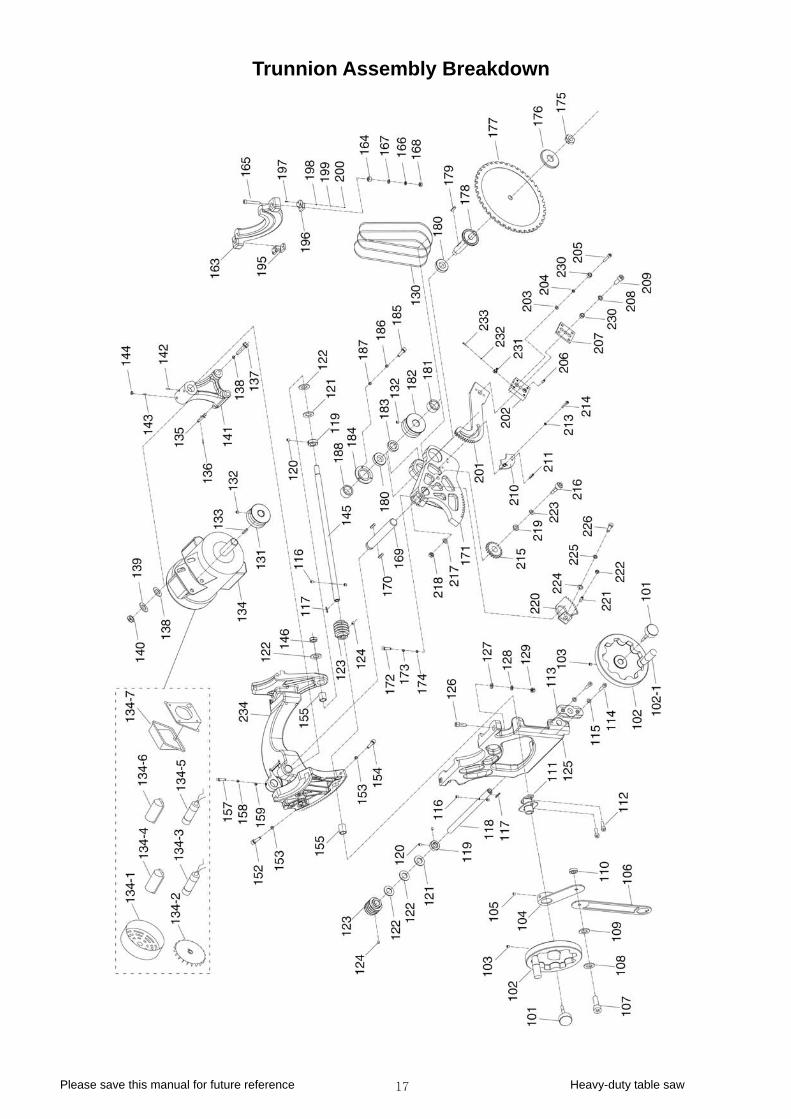
Trunnion Assembly Breakdown
e save this manual for future reference Heavy-duty table saw

Please save this manual for future reference Heavy-duty table saw 18
Trunnion Assembly Parts List
REF# DERIPTION QTY REF# DERIPTION QTY101 HAND WHEEL LOCK 2 164 ADJUST BOLT 2102 HAND WHEEL H NDLE 2 165 CAP SCREW M8-1.25×30 2
102-1 HAND WHEEL 2 166 FLAT WASHER 8MM 2103 SET SCREW M 8×12 2 167 LOCK WASHER 8MM 2104 ANGLE POIN R-1 1 168 HEX NUT M8-1.25 2105 SET SCREW M .8×6 1 169 HIGH SHAFT 1106 ANGLE POIN R-2 1 170 KEY 6×6×50 1107 CAP SCREW M 1×12 1 171 GEARED BEARING HOUSING 1108 LOCK WASHE 1 172 HEX BOLT M10-1.5×45 1109 FLAT WASHE MM 1 173 LOCK WASHER 10MM 1110 HEX NUT M 10MM 1111 ANGLE POINTER OR NUT 1112 CAP SCREW M R FLANGE 1113 PLATE 1 177 BLADE 10″40T 1
CAP 5
C
CO R
A
5-.TE5-
TE6-
R 6MM R 66-1 1 174 FLAT WASHER
BRACKET 1 175 ARB5-.8×25 2 176 ARBO
114 SCREW M8-1.25×2 2 178 BLADE ARBOR 1115 LOCK WASHER 8MM 2 179 KEY 5×5×30 1116 PIN-LOCK-SHAFT 4 180 BALL BEARING 6005 2Z 2117 KEY 5×5×36 2 181 OLLAR BLADE ARBOR 1118 ANGLE SHAFT 1 182 ARBOR PULLEY 1119 LOCK COLLAR 2 183 LLAR BLADE ARBO 1120 SET SCREW M6-1×8 4 184 FLANGE RING 1121 L PHLP 8×12
C
F RI
CAP 30 LOCK W 10MM F
LO M HE 5
SET 2 S FL
MOT PH CA 25
S R CAP A OVER
S C /4 S O
HE 00 FLA M CA 40 LO M FLA MM
MOTOR PORT
SET S 5×30 H 5
CA
FLA VE SET
SET SC -.7×12
OCK WASHER 18MM 2 185 HD SCR M5-. 3122 OPPER WASHER 18MM 4 186 LOCK WASHER 5MM 3123 WORM 2 187 FLAT WASHER 5MM 3124 SET SCREW M6-1×10 2 188 LOCK NUT M16-1.5 1125 RONT TRUNNION 1 195 LEFT BRACKET 1126 CAP SCREW M10-1.5×30 2 196 GHT BRACKET 1127 FLAT WASHER 10MM 2 197 SCREW M8-1.25× 4128 ASHER 2 198 LAT WASHER 8MM 4129 HEX NUT M10-1.5 2 199 CK WASHER 8M 4130 BELT SPZ 625 3 200 X NUT M8-1.2 4131 MOTOR PULLEY 1 201 BULL GEAR 1132 SCREW M5-.8×1 4 202 PLITTER ADJUST BLOCK 1133 KEY 5×5×30 1 203 AT WASHER 6MM 2134 OR 3HP 220V 1- 1 204 LOCK WASHER 6MM 2
134-1 FAN CONER 1 205 P SCREW M6-1× 2134-2 MOTOR FAN 1 206 SET SCREW M6-1×12 4134-3 R CAP 25M 370V 1-3/4×3 1 207 PLITTER TIGHTEN CLIP 1134-4 CITOR C 1 208 LOCK WASHER 6MM 1134-5 AP 200M 250V 1-1/4×2-3 1 209 HEX BOLT M6-1×20 1134-6 CAP ACITOR COVER 1 210 RIENTATION BAR 1134-7 WIRING JUNCTION BOX 1 211 ROLL PIN 5×25 2135 ORIENTATION PIN 1 213 LOCK WASHER 5MM 2136 ROLL PIN 4×28 1 214 CAP SCREW M5-.8×25 2137 X BOLT M12-1.75×1 1 215 GEAR 1138 T WASHER 12M 2 216 P SCREW M10-1.5× 1139 CK WASHER 12M 1 217 T WASHER 10 1140 HEX NUT M12-1.75 1 218 LOCK NUT M10-1.5 1141 FRAME SUP 1 219 GEAR SLEEVE 1142 SET SCREW M8-1.25×12 2 220 PLATE GEAR 1143 CREW M8-1.2 1 221 SET SCREW M6-1×20 3144 EX NUT M8-1.2 1 222 HEX NUT M6-1 3145 HIGH SHAFT 1 223 FENDER WASHER 10MM 1146 LOCK NUT M18-1.5 1 224 FLAT WASHER 8MM 1152 HEX BOLT M8-1.25×20 1 225 LOCK WASHER 8MM 1153 HEX NUT M8-1.25 2 226 P SCREW M8-1.25×20 1154 HEX BOLT M8-1.25×35 1 230 SPACER 3155 NGE CASTING SLEE 1 231 POSITION PIN SET 1157 SCREW M8-1.25×8 1 232 LOCK WASHER 4MM 2158 COMPRESSION SPRING 1 233 REW M4 2159 BALL 1 234 TRUNNION 1163 REAR TRUNNION 1
Please save this manual for future reference Heavy-duty table saw 19
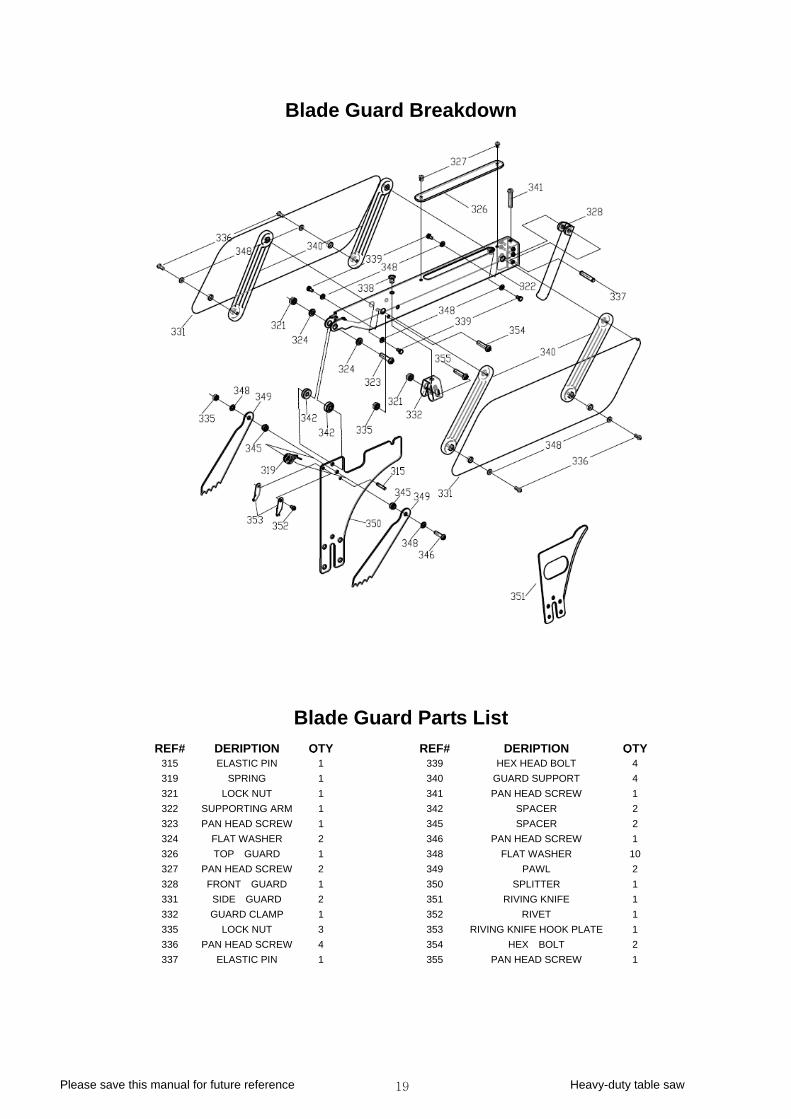
Blade Guard Breakdown
Blade Guard Parts List REF# DERIPTION QTY REF# DERIPTION QTY
315 ELASTIC PIN 1 339 HEX HEAD BOLT 4 319 SPRING 1 340 GUARD SUPPORT 321 LOCK NUT 1 341 PAN HEAD SCREW 1 322 SUPPORTING ARM 1 342 SPACER 2 323 PAN HEAD SCREW 1 345 SPACER 2 324 FLAT WASHER 2 346 PAN HEAD SCREW 1
4
326 TOP GUARD 1 348 FLAT WASHER 10 327 PAN HEAD SCREW 2 349 PAWL 2 328 FRONT GUARD 1 350 SPLITTER 1 331 SIDE GUARD 2 351 RIVING KNIFE 1 332 GUARD CLAMP RIVET 1 335 LOCK NUT IFE HOOK PLATE 1 336 PAN HEAD SCREW HEX BOLT 2
PA
1 3523 353 RIVING KN
4 354337 ELASTIC PIN 1 355 N HEAD SCREW 1
Please save this manual for future reference Heavy-duty table saw 20
it Gauge B kdow
REF# DESCRIPTION QT
M er rea n
Miter Gauge Parts List
Y REF# DESCRIPTION QTY 401A MITER GAUGE 1 420 MITER GAUGE FENCE 1 401 MITER BAR 1 421 SQUARE NUT 2 402 GIB 2 422 FLAT WASHER 4 403 SET SCREW M4-.7*6 4 423 ELASTIC WASHER 3 404 CAP SCREW M4-.7*14 2 424 LOCK LEVER 2 405 MITER RING 1 415 FLAT WASHER 4MM 1 406 FLAT HD SCR M5-.8*8 1 416 LOCK WASHER 4MM 1 407 MITER BODY PIVOT PIN 1 417 PHLP HD SCR M4-.7*8 1 408 MITER GUAGE BODY 1 418 MITER KNOB 1 409 MITER STOP PIN K ER WASHER 10MM 1 410 MITER STOP PIN BL HTEN SUPPORT 1 411 COMPRESSION SPRING 1 426 LOCK LEVER 1
M CAP *14
POINT AGE
NOB 1 419 FENDOCK 1 425 TIG
412 ITER STOP PIN 1 427 TIGHTEN PIN 1 413 SCREW M4-.7 2 428 TIGHTEN CLIP 1 414 ER MITER GU 1 429 LOCK NUT 1

Please save this manual for future reference Heavy-duty table saw 21
Fence Breakdown
11
Fence Parts List REF# DESCRIPTION QTY REF# DESCRIPTION QTY502 FANCE FACE 2 512 HEX BOLT M6-1*40 503 CAP SCREW M6-1*16 18 513 LOCK NUT M6-1 504 GLIDE PAD 2 514 HEX BOLT M10-1.5*45 505 FENCE SCALE WINDOW 1 515 LOCK NUT M10-1.25 506 SET SCREW M12-1.75*15 4 516 CAM FOOT 507 PHLP HD SCR M5-.8*10 2 517 MAGNET 1508 LOCK WASHER 5MM 2 518 CAM 1509 INDICATOR 2 519 FENCE LOCK KNOB 510 FENCE BODY 1 520 SET SCREW M12-1.75*30 511 SET SCREW 2 521 SPECIAL LOCKING NUT M12-1.75
111
114
Please save this manual for future reference Heavy-duty table saw 22
30”Rail & Extension Table Breakdown
606 LOCK WASHER 6MM 13 614 TABLE BOARD 1 607 FLAT WASHER 6MM 13 615 HEX BOLT M8-1.25*30 3 608 HEX BOLT 5/16-18*1-1/2 2
30”Rail & Extension Table Parts List
REF# DESCRIPTION QTY REF# DESCRIPTION QTY601 INSERT FENCE 2 609 LOCK WASHER 8MM 22602 GUIDE TUBE 1 610 FLAT WASHER 8MM 34603 SCALE 1 611 REAR RAIL 1 604 FRONT RAIL 1 612 HEX BOLT M8-1.25*40 6 605 CAP SCREW M6-1*16 5 613 HEX NUT M8-1.25 18
Please save this manual for future reference Heavy-duty table saw 23
50”Rail & Extension Table Breakdown
609 LOCK WASHER 8MM 22 620 HEX BOLT M8-1.25*30 3610 FLAT WASHER 8MM 34 621 GUIDE TUBE 1612 HEX B 1613 HE IL 1614 TA 1
50”Rail & Extension Table Parts List
REF# DESCRIPTION QTY REF# DESCRIPTION QTY601 INSERT FENCE 2 615 LEG 2605 CAP SCREW M6-1*16 5 616 FOOT 2606 LOCK WASHER 6MM 13 617 HEX BOLT M8-1.25×60 2607 FLAT WASHER 6MM 13 618 CAP SCREW M6-1*16 6608 HEX BOLT 5/16-18*1-1/2 2 619 CAP SCREW M8-1.25*20 4
OLT M8-1.25*40 6 622 SCALE X NUT M8-1.25 18 623 FRONT RA
BLE BOARD 1 624 REAR RAIL