Embed Size (px)
Citation preview
8/6/2019 Plc Adv Func
http://slidepdf.com/reader/full/plc-adv-func 1/28
287
16. ADVANCED LADDER LOGIC FUNCTIONS
16.1 INTRODUCTION
This chapter covers advanced functions, but this definition is somewhat arbitrary. The array
functions in the last chapter could be classified as advanced functions. The functions in this section tend
to do things that are not oriented to simple data values. The list functions will allow storage and recov-
ery of bits and words. These functions are useful when implementing buffered and queued systems. The
program control functions will do things that don’t follow the simple model of ladder logic execution -these functions recognize the program is executed left-to-right top-to-bottom. Finally, the input output
functions will be discussed, and how they allow us to work around the normal input and output scans.
16.2 LIST FUNCTIONS
16.2.1 Shift Registers
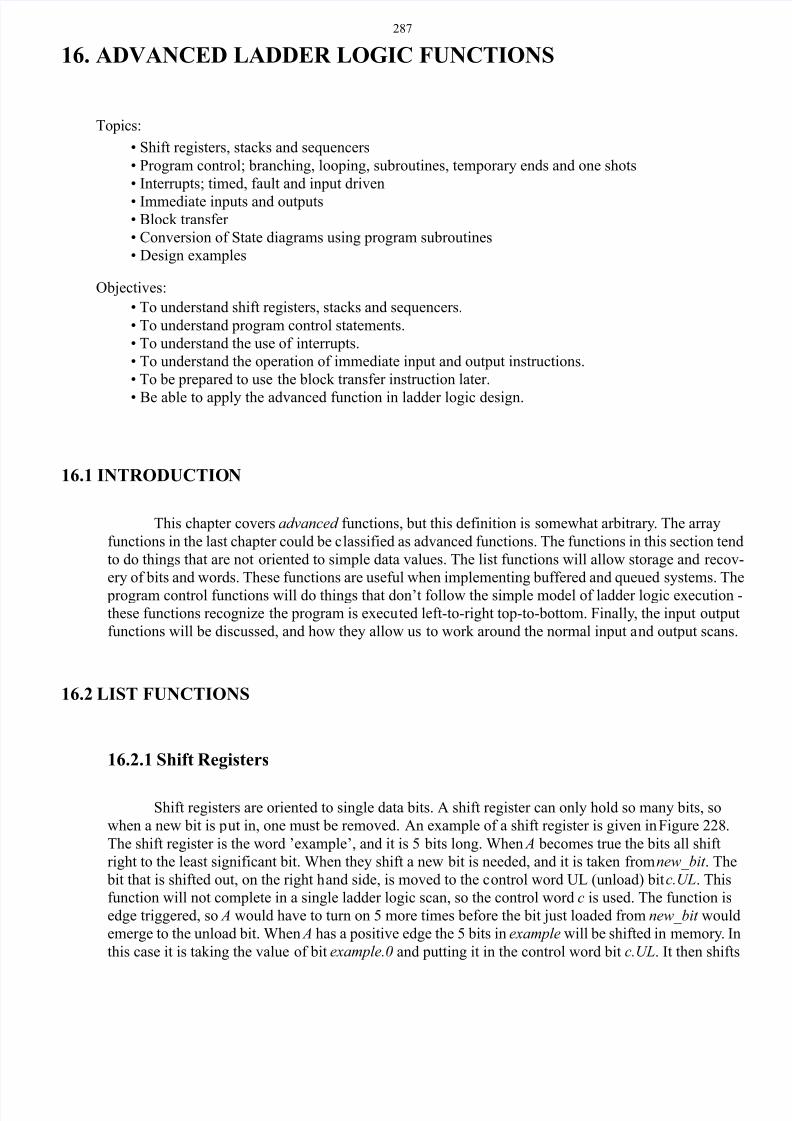
Shift registers are oriented to single data bits. A shift register can only hold so many bits, so
when a new bit is put in, one must be removed. An example of a shift register is given in Figure 228.
The shift register is the word ’example’, and it is 5 bits long. When A becomes true the bits all shift
right to the least significant bit. When they shift a new bit is needed, and it is taken from new_bit . The
bit that is shifted out, on the right hand side, is moved to the control word UL (unload) bit c.UL. This
function will not complete in a single ladder logic scan, so the control word c is used. The function is
edge triggered, so A would have to turn on 5 more times before the bit just loaded from new_bit would
emerge to the unload bit. When A has a positive edge the 5 bits in example will be shifted in memory. In
this case it is taking the value of bit example.0 and putting it in the control word bit c.UL. It then shifts
Topics:
Objectives:
• To understand shift registers, stacks and sequencers.
• To understand program control statements.
• To understand the use of interrupts.
• To understand the operation of immediate input and output instructions.
• To be prepared to use the block transfer instruction later.
• Be able to apply the advanced function in ladder logic design.
• Shift registers, stacks and sequencers
• Program control; branching, looping, subroutines, temporary ends and one shots
• Interrupts; timed, fault and input driven
• Immediate inputs and outputs• Block transfer
• Conversion of State diagrams using program subroutines
• Design examples
8/6/2019 Plc Adv Func
http://slidepdf.com/reader/full/plc-adv-func 2/28
288
the bits once to the right, example.0 = example.1 then example.1 = example.2 then example.2 = exam-
ple.3 then example.3 = example.4. Then the input bit is put into the most significant bit example.4 =
new_bit . The bits in the shift register would be shifted to the left with the BSR function.
Figure 228 Shift Register Functions
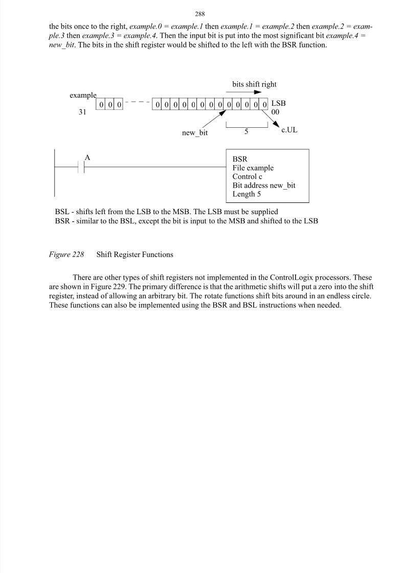
There are other types of shift registers not implemented in the ControlLogix processors. These
are shown in Figure 229. The primary difference is that the arithmetic shifts will put a zero into the shift
register, instead of allowing an arbitrary bit. The rotate functions shift bits around in an endless circle.
These functions can also be implemented using the BSR and BSL instructions when needed.
0 0 0 0 0 0 0 0 0 0 0 0 0 0 0 0
BSR File exampleControl cBit address new_bitLength 5
example
31LSB00
5
bits shift right
new_bit c.UL
BSL - shifts left from the LSB to the MSB. The LSB must be supplied
BSR - similar to the BSL, except the bit is input to the MSB and shifted to the LSB
A
8/6/2019 Plc Adv Func
http://slidepdf.com/reader/full/plc-adv-func 3/28
289
Figure 229 Shift Register Variations
16.2.2 Stacks
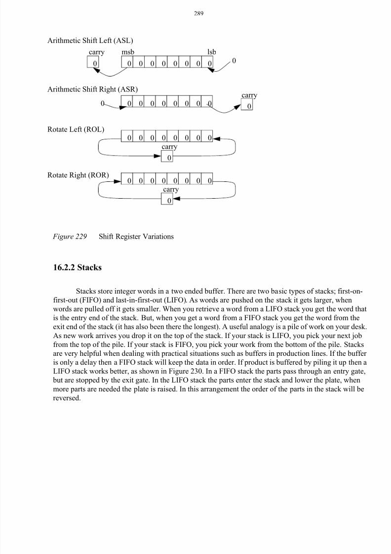
Stacks store integer words in a two ended buffer. There are two basic types of stacks; first-on-first-out (FIFO) and last-in-first-out (LIFO). As words are pushed on the stack it gets larger, when
words are pulled off it gets smaller. When you retrieve a word from a LIFO stack you get the word that
is the entry end of the stack. But, when you get a word from a FIFO stack you get the word from the
exit end of the stack (it has also been there the longest). A useful analogy is a pile of work on your desk.
As new work arrives you drop it on the top of the stack. If your stack is LIFO, you pick your next job
from the top of the pile. If your stack is FIFO, you pick your work from the bottom of the pile. Stacks
are very helpful when dealing with practical situations such as buffers in production lines. If the buffer
is only a delay then a FIFO stack will keep the data in order. If product is buffered by piling it up then a
LIFO stack works better, as shown in Figure 230. In a FIFO stack the parts pass through an entry gate,
but are stopped by the exit gate. In the LIFO stack the parts enter the stack and lower the plate, when
more parts are needed the plate is raised. In this arrangement the order of the parts in the stack will bereversed.
0 0 0 0 0 0 0 00 0
0 0 0 0 0 0 0 0 00
0 0 0 0 0 0 0 0
0
0 0 0 0 0 0 0 0
0
carry
carry
Arithmetic Shift Right (ASR)
Arithmetic Shift Left (ASL)
Rotate Left (ROL)
Rotate Right (ROR)
carry
carry
msb lsb
8/6/2019 Plc Adv Func
http://slidepdf.com/reader/full/plc-adv-func 4/28
290
Figure 230 Buffers and Stack Types
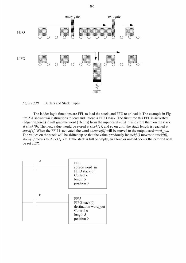
The ladder logic functions are FFL to load the stack, and FFU to unload it. The example in Fig-
ure 231 shows two instructions to load and unload a FIFO stack. The first time this FFL is activated
(edge triggered) it will grab the word (16 bits) from the input card word_in and store them on the stack,
at stack[0]. The next value would be stored at stack[1], and so on until the stack length is reached at
stack[4]. When the FFU is activated the word at stack[0] will be moved to the output card word_out .
The values on the stack will be shifted up so that the value previously in stack[1] moves to stack[0],
stack[2] moves to stack[1], etc. If the stack is full or empty, an a load or unload occurs the error bit will be set c.ER.
FIFO
LIFO
entry gate exit gate
FFLsource word_inFIFO stack[0]Control clength 5
position 0
FFUFIFO stack[0]destination word_outControl clength 5 position 0
A
B
8/6/2019 Plc Adv Func
http://slidepdf.com/reader/full/plc-adv-func 5/28
291
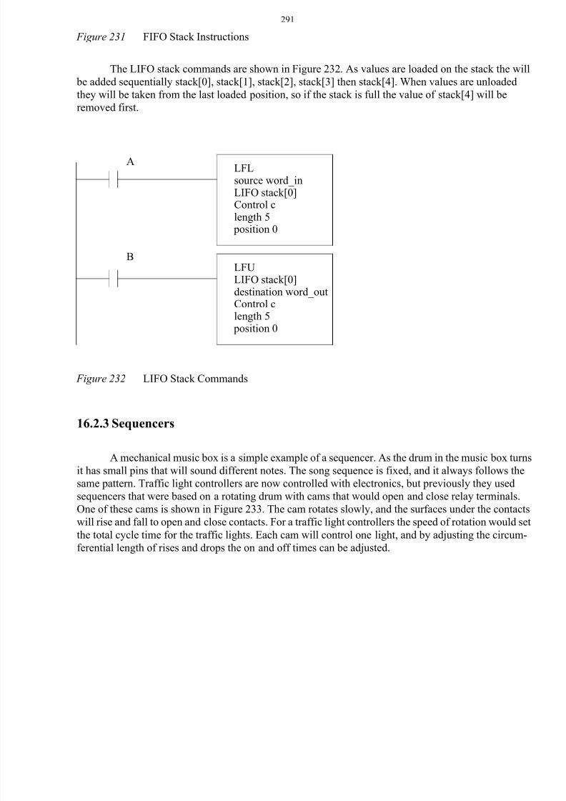
Figure 231 FIFO Stack Instructions
The LIFO stack commands are shown in Figure 232. As values are loaded on the stack the will
be added sequentially stack[0], stack[1], stack[2], stack[3] then stack[4]. When values are unloaded
they will be taken from the last loaded position, so if the stack is full the value of stack[4] will be
removed first.
Figure 232 LIFO Stack Commands
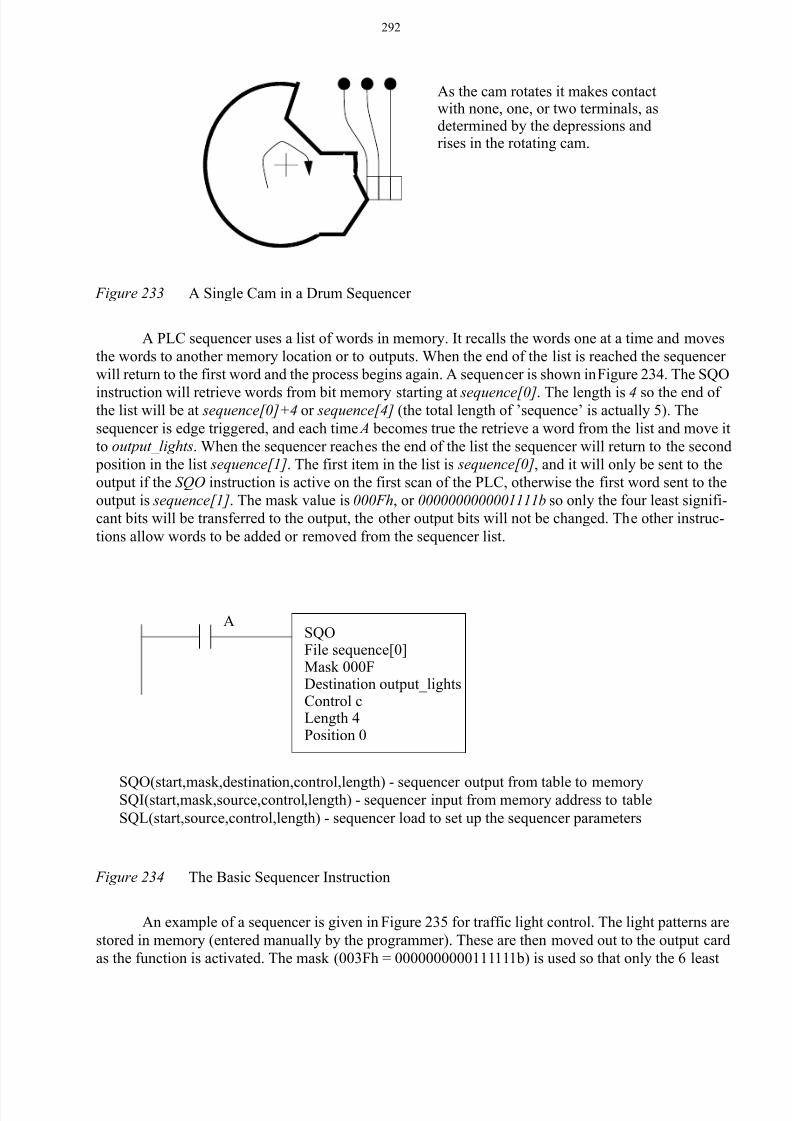
16.2.3 Sequencers
A mechanical music box is a simple example of a sequencer. As the drum in the music box turns
it has small pins that will sound different notes. The song sequence is fixed, and it always follows the
same pattern. Traffic light controllers are now controlled with electronics, but previously they used
sequencers that were based on a rotating drum with cams that would open and close relay terminals.
One of these cams is shown in Figure 233. The cam rotates slowly, and the surfaces under the contacts
will rise and fall to open and close contacts. For a traffic light controllers the speed of rotation would set
the total cycle time for the traffic lights. Each cam will control one light, and by adjusting the circum-
ferential length of rises and drops the on and off times can be adjusted.
LFLsource word_inLIFO stack[0]Control clength 5 position 0
LFU
LIFO stack[0]destination word_outControl clength 5 position 0
A
B
8/6/2019 Plc Adv Func
http://slidepdf.com/reader/full/plc-adv-func 6/28
292
Figure 233 A Single Cam in a Drum Sequencer
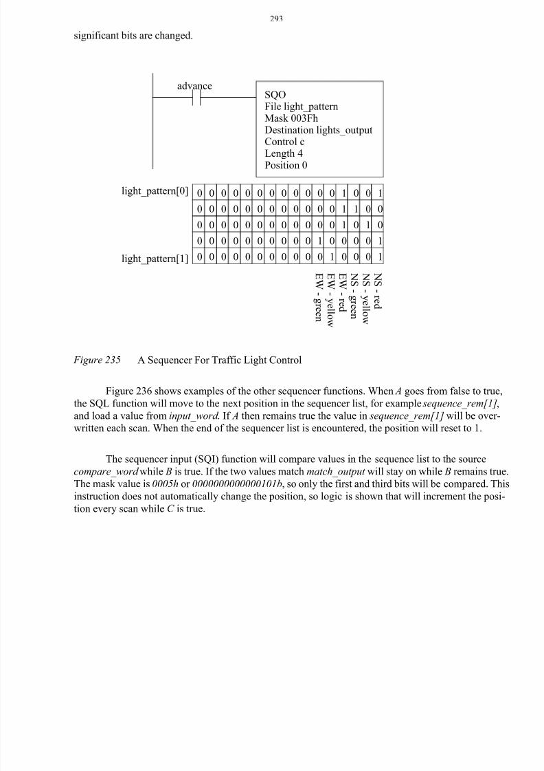
A PLC sequencer uses a list of words in memory. It recalls the words one at a time and moves
the words to another memory location or to outputs. When the end of the list is reached the sequencer
will return to the first word and the process begins again. A sequencer is shown in Figure 234. The SQO
instruction will retrieve words from bit memory starting at sequence[0]. The length is 4 so the end of the list will be at sequence[0]+4 or sequence[4] (the total length of ’sequence’ is actually 5). The
sequencer is edge triggered, and each time A becomes true the retrieve a word from the list and move it
to output_lights. When the sequencer reaches the end of the list the sequencer will return to the second
position in the list sequence[1]. The first item in the list is sequence[0], and it will only be sent to the
output if the SQO instruction is active on the first scan of the PLC, otherwise the first word sent to the
output is sequence[1]. The mask value is 000Fh, or 0000000000001111b so only the four least signifi-
cant bits will be transferred to the output, the other output bits will not be changed. The other instruc-
tions allow words to be added or removed from the sequencer list.
Figure 234 The Basic Sequencer Instruction
An example of a sequencer is given in Figure 235 for traffic light control. The light patterns are
stored in memory (entered manually by the programmer). These are then moved out to the output card
as the function is activated. The mask (003Fh = 0000000000111111b) is used so that only the 6 least
As the cam rotates it makes contactwith none, one, or two terminals, asdetermined by the depressions andrises in the rotating cam.
SQO(start,mask,destination,control,length) - sequencer output from table to memorySQI(start,mask,source,control,length) - sequencer input from memory address to table
SQL(start,source,control,length) - sequencer load to set up the sequencer parameters
SQOFile sequence[0]Mask 000FDestination output_lightsControl cLength 4Position 0
A
8/6/2019 Plc Adv Func
http://slidepdf.com/reader/full/plc-adv-func 7/28
293
significant bits are changed.
Figure 235 A Sequencer For Traffic Light Control
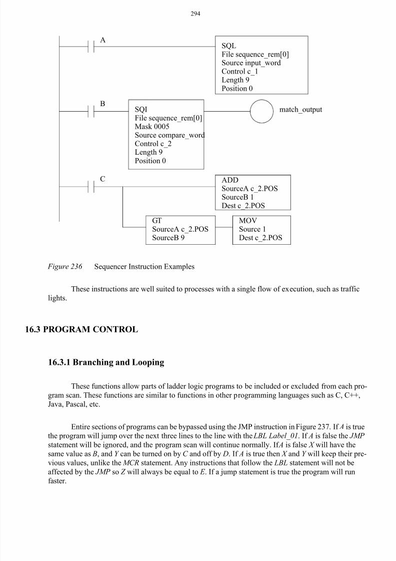
Figure 236 shows examples of the other sequencer functions. When A goes from false to true,
the SQL function will move to the next position in the sequencer list, for example sequence_rem[1],and load a value from input_word . If A then remains true the value in sequence_rem[1] will be over-
written each scan. When the end of the sequencer list is encountered, the position will reset to 1.
The sequencer input (SQI) function will compare values in the sequence list to the source
compare_word while B is true. If the two values match match_output will stay on while B remains true.
The mask value is 0005h or 0000000000000101b, so only the first and third bits will be compared. This
instruction does not automatically change the position, so logic is shown that will increment the posi-
tion every scan while C is true.
SQOFile light_patternMask 003Fh
Destination lights_outputControl cLength 4Position 0
0 0 0 0 0 0 0 0 0 0 0 0 1 1 0 0
0 0 0 0 0 0 0 0 0 0 0 0 1 0 1 0
0 0 0 0 0 0 0 0 0 0 1 0 0 0 0 1
0 0 0 0 0 0 0 0 0 0 0 1 0 0 0 1
light_pattern[0]
light_pattern[1] N S -r e d
N S - y e l l o w
N S - gr e e n
E W -r e d
E W - y e l l o w
E W - gr e e n
0 0 0 0 0 0 0 0 0 0 0 0 1 0 0 1
advance
8/6/2019 Plc Adv Func
http://slidepdf.com/reader/full/plc-adv-func 8/28
294
Figure 236 Sequencer Instruction Examples
These instructions are well suited to processes with a single flow of execution, such as traffic
lights.
16.3 PROGRAM CONTROL
16.3.1 Branching and Looping
These functions allow parts of ladder logic programs to be included or excluded from each pro-
gram scan. These functions are similar to functions in other programming languages such as C, C++,Java, Pascal, etc.
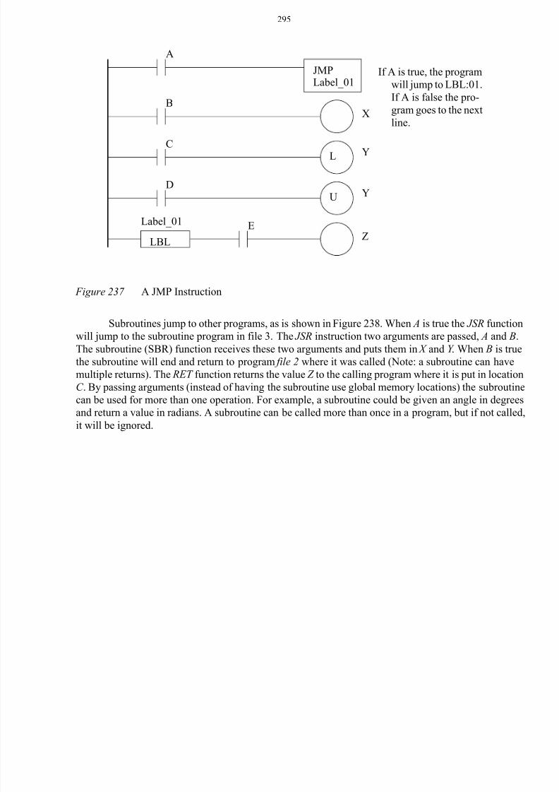
Entire sections of programs can be bypassed using the JMP instruction in Figure 237. If A is true
the program will jump over the next three lines to the line with the LBL Label_01. If A is false the JMP
statement will be ignored, and the program scan will continue normally. If A is false X will have the
same value as B, and Y can be turned on by C and off by D. If A is true then X and Y will keep their pre-
vious values, unlike the MCR statement. Any instructions that follow the LBL statement will not be
affected by the JMP so Z will always be equal to E . If a jump statement is true the program will run
faster.
SQIFile sequence_rem[0]Mask 0005Source compare_wordControl c_2Length 9Position 0
B
SQLFile sequence_rem[0]Source input_wordControl c_1Length 9Position 0
A
match_output
ADDSourceA c_2.POS
SourceB 1Dest c_2.POS
C
MOVSource 1Dest c_2.POS
GTSourceA c_2.POSSourceB 9
8/6/2019 Plc Adv Func
http://slidepdf.com/reader/full/plc-adv-func 9/28
295
Figure 237 A JMP Instruction
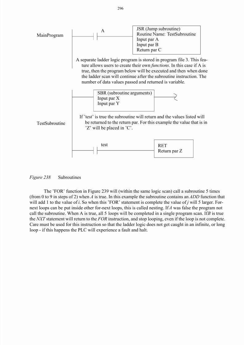
Subroutines jump to other programs, as is shown in Figure 238. When A is true the JSR function
will jump to the subroutine program in file 3. The JSR instruction two arguments are passed, A and B.
The subroutine (SBR) function receives these two arguments and puts them in X and Y . When B is true
the subroutine will end and return to program file 2 where it was called (Note: a subroutine can have
multiple returns). The RET function returns the value Z to the calling program where it is put in location
C . By passing arguments (instead of having the subroutine use global memory locations) the subroutine
can be used for more than one operation. For example, a subroutine could be given an angle in degrees
and return a value in radians. A subroutine can be called more than once in a program, but if not called,it will be ignored.
A
LBL
JMPLabel_01
If A is true, the program
will jump to LBL:01.
If A is false the pro-
gram goes to the next
line.
B
CL
DU
X
Y
Y
EZ
Label_01
8/6/2019 Plc Adv Func
http://slidepdf.com/reader/full/plc-adv-func 10/28
296
Figure 238 Subroutines
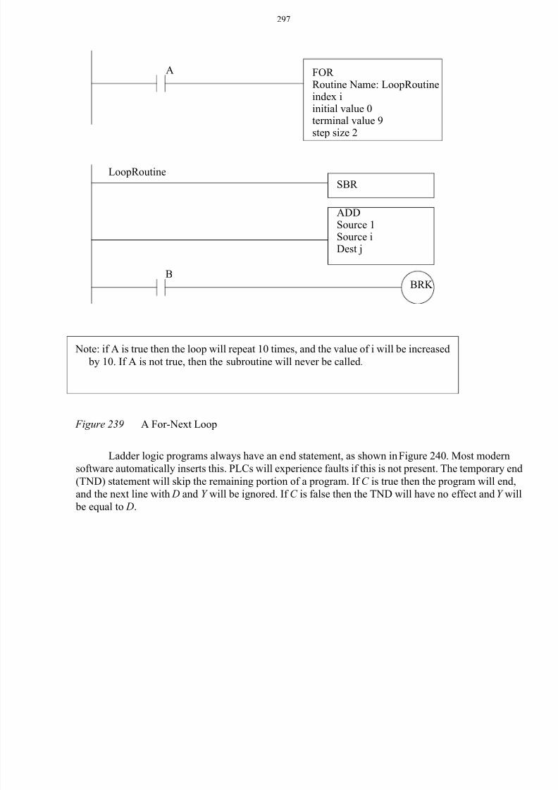
The ’FOR’ function in Figure 239 will (within the same logic scan) call a subroutine 5 times
(from 0 to 9 in steps of 2) when A is true. In this example the subroutine contains an ADD function that
will add 1 to the value of i. So when this ’FOR’ statement is complete the value of j will 5 larger. For-
next loops can be put inside other for-next loops, this is called nesting. If A was false the program not
call the subroutine. When A is true, all 5 loops will be completed in a single program scan. If B is true
the NXT statement will return to the FOR instruction, and stop looping, even if the loop is not complete.
Care must be used for this instruction so that the ladder logic does not get caught in an infinite, or long
loop - if this happens the PLC will experience a fault and halt.
A JSR (Jump subroutine)
test
MainProgram
TestSubroutine
Routine Name: TestSubroutineInput par AInput par BReturn par C
SBR (subroutine arguments)Input par X
A separate ladder logic program is stored in program file 3. This fea-ture allows users to create their own functions. In this case if A is
true, then the program below will be executed and then when done
the ladder scan will continue after the subroutine instruction. The
number of data values passed and returned is variable.
If ’test’ is true the subroutine will return and the values listed will
be returned to the return par. For this example the value that is in’Z’ will be placed in ’C’.
RETReturn par Z
Input par Y
8/6/2019 Plc Adv Func
http://slidepdf.com/reader/full/plc-adv-func 11/28
297
Figure 239 A For-Next Loop
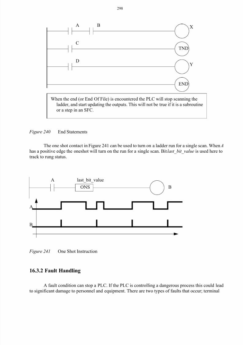
Ladder logic programs always have an end statement, as shown in Figure 240. Most modern
software automatically inserts this. PLCs will experience faults if this is not present. The temporary end
(TND) statement will skip the remaining portion of a program. If C is true then the program will end,
and the next line with D and Y will be ignored. If C is false then the TND will have no effect and Y will
be equal to D.
FOR Routine Name: LoopRoutineindex iinitial value 0terminal value 9
step size 2
ADDSource 1Source iDest j
A
Note: if A is true then the loop will repeat 10 times, and the value of i will be increased
by 10. If A is not true, then the subroutine will never be called.
BRK B
LoopRoutine
SBR
8/6/2019 Plc Adv Func
http://slidepdf.com/reader/full/plc-adv-func 12/28
298
Figure 240 End Statements
The one shot contact in Figure 241 can be used to turn on a ladder run for a single scan. When A
has a positive edge the oneshot will turn on the run for a single scan. Bit last_bit_value is used here to
track to rung status.
Figure 241 One Shot Instruction
16.3.2 Fault Handling
A fault condition can stop a PLC. If the PLC is controlling a dangerous process this could lead
to significant damage to personnel and equipment. There are two types of faults that occur; terminal
A
END
B X
When the end (or End Of File) is encountered the PLC will stop scanning the
ladder, and start updating the outputs. This will not be true if it is a subroutine
or a step in an SFC.
CTND
DY
AONS
last_bit_valueB
A
B
8/6/2019 Plc Adv Func
http://slidepdf.com/reader/full/plc-adv-func 13/28
299
(major) and warnings (minor). A minor fault will normally set an error bit, but not stop the PLC. A
major failure will normally stop the PLC, but an interrupt can be used to run a program that can reset
the fault bit in memory and continue operation (or shut down safely). Not all major faults are recover-
able. A complete list of these faults is available in PLC processor manuals.
The PLC can be set up to run a program when a fault occurs, such as a divide by zero. These
routines are program files under ’Control Fault Handler’. These routines will be called when a fault
occurs. Values are set in status memory to indicate the source of the faults.
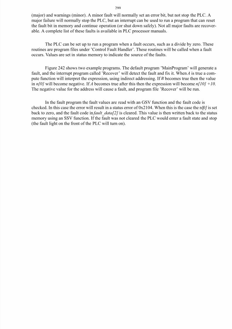
Figure 242 shows two example programs. The default program ’MainProgram’ will generate a
fault, and the interrupt program called ’Recover’ will detect the fault and fix it. When A is true a com-
pute function will interpret the expression, using indirect addressing. If B becomes true then the value
in n[0] will become negative. If A becomes true after this then the expression will become n[10] +10.
The negative value for the address will cause a fault, and program file ’Recover’ will be run.
In the fault program the fault values are read with an GSV function and the fault code is
checked. In this case the error will result in a status error of 0x2104. When this is the case the n[0] is set
back to zero, and the fault code in fault_data[2] is cleared. This value is then written back to the status
memory using an SSV function. If the fault was not cleared the PLC would enter a fault state and stop
(the fault light on the front of the PLC will turn on).
8/6/2019 Plc Adv Func
http://slidepdf.com/reader/full/plc-adv-func 14/28
300
Figure 242 A Fault Recovery Program
16.3.3 Interrupts
The PLC can be set up to run programs automatically using interrupts. This is routinely done for
a few reasons;
• to run a program at a regular timed interval (e.g. SPC calculations)
• to respond when a long instruction is complete (e.g. analog input)
• when a certain input changed (e.g. panic button)
Allen Bradley allows interrupts, but they are called periodic/event tasks. By default the main
program is defined as a ’continuous’ task, meaning that it runs as often as possible, typically 10-100
CPTDest n[1]Expressionn[n[0]] + 10
A
EQUSourceA fault_data[2]SourceB 0x2104
CLR Dest. fault_data[2]
MainProgram
Recover
MOVSource 0Dest N7:0
MOVSource -10Dest n[0]
B
GSVObject: PROGRAMInstance: THISAttribute: MAJORFAULTRECORDDest: fault_data (Note: DINT[11])
SSVObject: PROGRAMInstance: THISAttribute: MAJORFAULTRECORDDest: fault_data

8/6/2019 Plc Adv Func
http://slidepdf.com/reader/full/plc-adv-func 15/28
301
times per second. Only one continuos task is allowed. A ’periodic’ task can be created that has a given
update time. ’Event’ tasks can be triggered by a variety of actions, including input changes, tag
changes, EVENT instructions, and servo control changes.
A timed interrupt will run a program at regular intervals. To set a timed interrupt the program in
file number should be put in S2:31. The program will be run every S2:30 times 1 milliseconds. In Fig-
ure 243 program 2 will set up an interrupt that will run program 3 every 5 seconds. Program 3 will add
the value of I:000 to N7:10. This type of timed interrupt is very useful when controlling processes
where a constant time interval is important. The timed interrupts are enabled by setting bit S2:2/1 in
PLC-5s.
When activated, interrupt routines will stop the PLC, and the ladder logic is interpreted immedi-
ately. If multiple interrupts occur at the same time the ones with the higher priority will occur first. If
the PLC is in the middle of a program scan when interrupted this can cause problems. To overcome this
a program can disable interrupts temporarily using the UID and UIE functions. Figure 243 shows an
example where the interrupts are disabled for a FAL instruction. Only the ladder logic between the UID
and UIE will be disabled, the first line of ladder logic could be interrupted. This would be important if
an interrupt routine could change a value between n[0] and n[4]. For example, an interrupt could occur
while the FAL instruction was at n[7]=n[2]+5. The interrupt could change the values of n[1] and n[4],and then end. The FAL instruction would then complete the calculations. But, the results would be
based on the old value for n[1] and the new value for n[4].
Figure 243 Disabling Interrupts
UID
XA
UIE
FALControl clength 5 position 0Mode allDestination n[5 + c.POS]Expression n[c.POS] + 5
B
8/6/2019 Plc Adv Func
http://slidepdf.com/reader/full/plc-adv-func 16/28
302
16.4 INPUT AND OUTPUT FUNCTIONS
16.4.1 Immediate I/O Instructions
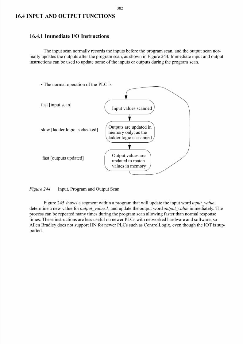
The input scan normally records the inputs before the program scan, and the output scan nor-
mally updates the outputs after the program scan, as shown in Figure 244. Immediate input and output
instructions can be used to update some of the inputs or outputs during the program scan.
Figure 244 Input, Program and Output Scan
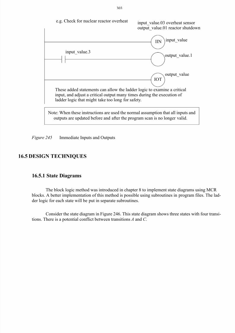
Figure 245 shows a segment within a program that will update the input word input_value,
determine a new value for output_value.1, and update the output word output_value immediately. The
process can be repeated many times during the program scan allowing faster than normal response
times. These instructions are less useful on newer PLCs with networked hardware and software, so
Allen Bradley does not support IIN for newer PLCs such as ControlLogix, even though the IOT is sup-
ported.
• The normal operation of the PLC is
fast [input scan]
slow [ladder logic is checked]
fast [outputs updated]
Input values scanned
Outputs are updated inmemory only, as theladder logic is scanned
Output values areupdated to matchvalues in memory
8/6/2019 Plc Adv Func
http://slidepdf.com/reader/full/plc-adv-func 17/28
303
Figure 245 Immediate Inputs and Outputs
16.5 DESIGN TECHNIQUES
16.5.1 State Diagrams
The block logic method was introduced in chapter 8 to implement state diagrams using MCR
blocks. A better implementation of this method is possible using subroutines in program files. The lad-
der logic for each state will be put in separate subroutines.
Consider the state diagram in Figure 246. This state diagram shows three states with four transi-
tions. There is a potential conflict between transitions A and C .
e.g. Check for nuclear reactor overheat input_value.03 overheat sensor output_value.01 reactor shutdown
input_valueIIN
IOToutput_value
These added statements can allow the ladder logic to examine a criticalinput, and adjust a critical output many times during the execution of ladder logic that might take too long for safety.
input_value.3output_value.1
Note: When these instructions are used the normal assumption that all inputs and
outputs are updated before and after the program scan is no longer valid.

8/6/2019 Plc Adv Func
http://slidepdf.com/reader/full/plc-adv-func 18/28
304
Figure 246 A State Diagram
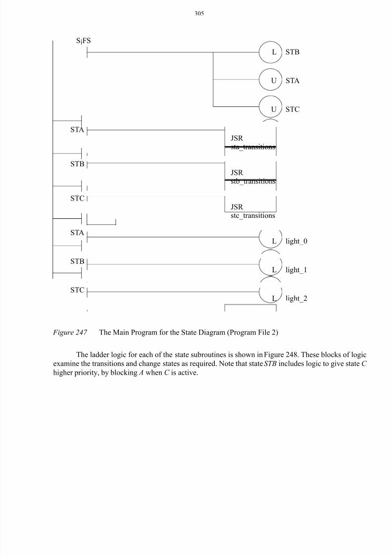
The main program for the state diagram is shown in Figure 247. This program is stored in the
MainProgram so that it is run by default. The first rung in the program resets the states so that the firstscan state is on, while the other states are turned off. The following logic will call the subroutine for
each state. The logic that uses the current state is placed in the main program. It is also possible to put
this logic in the state subroutines.
first scan
STA
STB
STC
A
B
C
D
light_0 = STA
light_1 = STB
light_2 = STC
8/6/2019 Plc Adv Func
http://slidepdf.com/reader/full/plc-adv-func 19/28
305
Figure 247 The Main Program for the State Diagram (Program File 2)
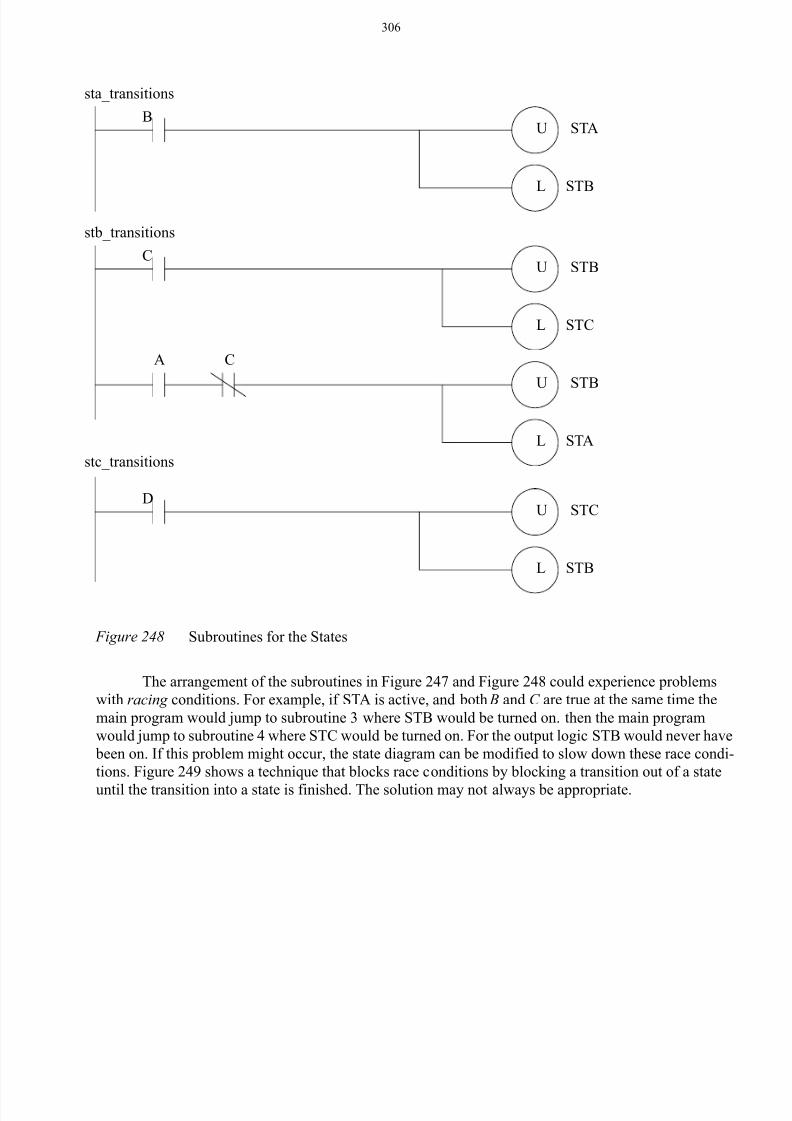
The ladder logic for each of the state subroutines is shown in Figure 248. These blocks of logic
examine the transitions and change states as required. Note that state STB includes logic to give state C
higher priority, by blocking A when C is active.
S:FS
L
U
U
STA
STB
STC
STAJSR sta_transitions
STBJSR stb_transitions
STCJSR stc_transitions
L light_0
L light_1
L light_2
STA
STB
STC
8/6/2019 Plc Adv Func
http://slidepdf.com/reader/full/plc-adv-func 20/28
306
Figure 248 Subroutines for the States
The arrangement of the subroutines in Figure 247 and Figure 248 could experience problems
with racing conditions. For example, if STA is active, and both B and C are true at the same time the
main program would jump to subroutine 3 where STB would be turned on. then the main program
would jump to subroutine 4 where STC would be turned on. For the output logic STB would never have
been on. If this problem might occur, the state diagram can be modified to slow down these race condi-
tions. Figure 249 shows a technique that blocks race conditions by blocking a transition out of a state
until the transition into a state is finished. The solution may not always be appropriate.
U
L STB
STCD
stc_transitions
U
L STC
STBC
U
L STA
STB
CA
stb_transitions
sta_transitions
U
L STB
STAB
8/6/2019 Plc Adv Func
http://slidepdf.com/reader/full/plc-adv-func 21/28
307
Figure 249 A Modified State Diagram to Prevent Racing
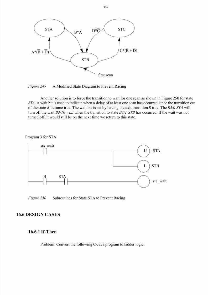
Another solution is to force the transition to wait for one scan as shown in Figure 250 for state
STA. A wait bit is used to indicate when a delay of at least one scan has occurred since the transition outof the state B became true. The wait bit is set by having the exit transition B true. The B3/0-STA will
turn off the wait B3/10-wait when the transition to state B3/1-STB has occurred. If the wait was not
turned off, it would still be on the next time we return to this state.
Figure 250 Subroutines for State STA to Prevent Racing
16.6 DESIGN CASES
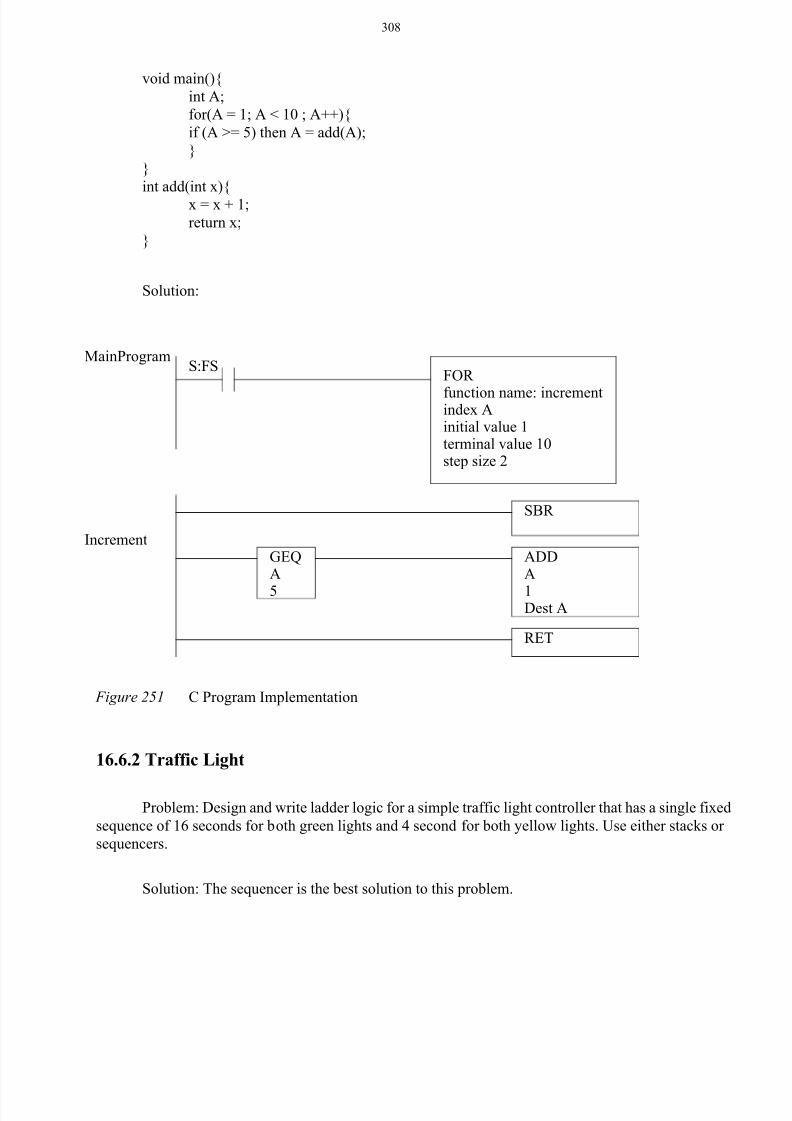
16.6.1 If-Then
Problem: Convert the following C/Java program to ladder logic.
first scan
STA
STB
STC
A*(B + D)
B*A
C*(B + D)
D*C
Program 3 for STA
sta_waitB
U
L STB
STAsta_wait
STA
8/6/2019 Plc Adv Func
http://slidepdf.com/reader/full/plc-adv-func 22/28
308
Solution:
Figure 251 C Program Implementation
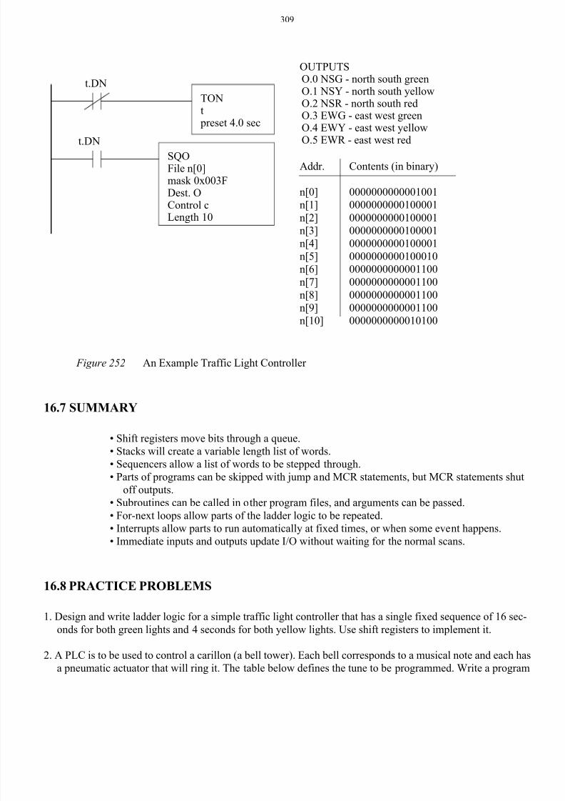
16.6.2 Traffic Light
Problem: Design and write ladder logic for a simple traffic light controller that has a single fixed
sequence of 16 seconds for both green lights and 4 second for both yellow lights. Use either stacks or
sequencers.
Solution: The sequencer is the best solution to this problem.
void main(){
int A;
for(A = 1; A < 10 ; A++){
if (A >= 5) then A = add(A);
}
}
int add(int x){
x = x + 1;
return x;
}
S:FS
SBR
MainProgram
Increment
RET
ADDA
1Dest A
FOR
function name: incrementindex Ainitial value 1terminal value 10step size 2
GEQA
5
8/6/2019 Plc Adv Func
http://slidepdf.com/reader/full/plc-adv-func 23/28
309
Figure 252 An Example Traffic Light Controller
16.7 SUMMARY
• Shift registers move bits through a queue.
• Stacks will create a variable length list of words.
• Sequencers allow a list of words to be stepped through.
• Parts of programs can be skipped with jump and MCR statements, but MCR statements shut
off outputs.
• Subroutines can be called in other program files, and arguments can be passed.
• For-next loops allow parts of the ladder logic to be repeated.
• Interrupts allow parts to run automatically at fixed times, or when some event happens.
• Immediate inputs and outputs update I/O without waiting for the normal scans.
16.8 PRACTICE PROBLEMS
1. Design and write ladder logic for a simple traffic light controller that has a single fixed sequence of 16 sec-
onds for both green lights and 4 seconds for both yellow lights. Use shift registers to implement it.
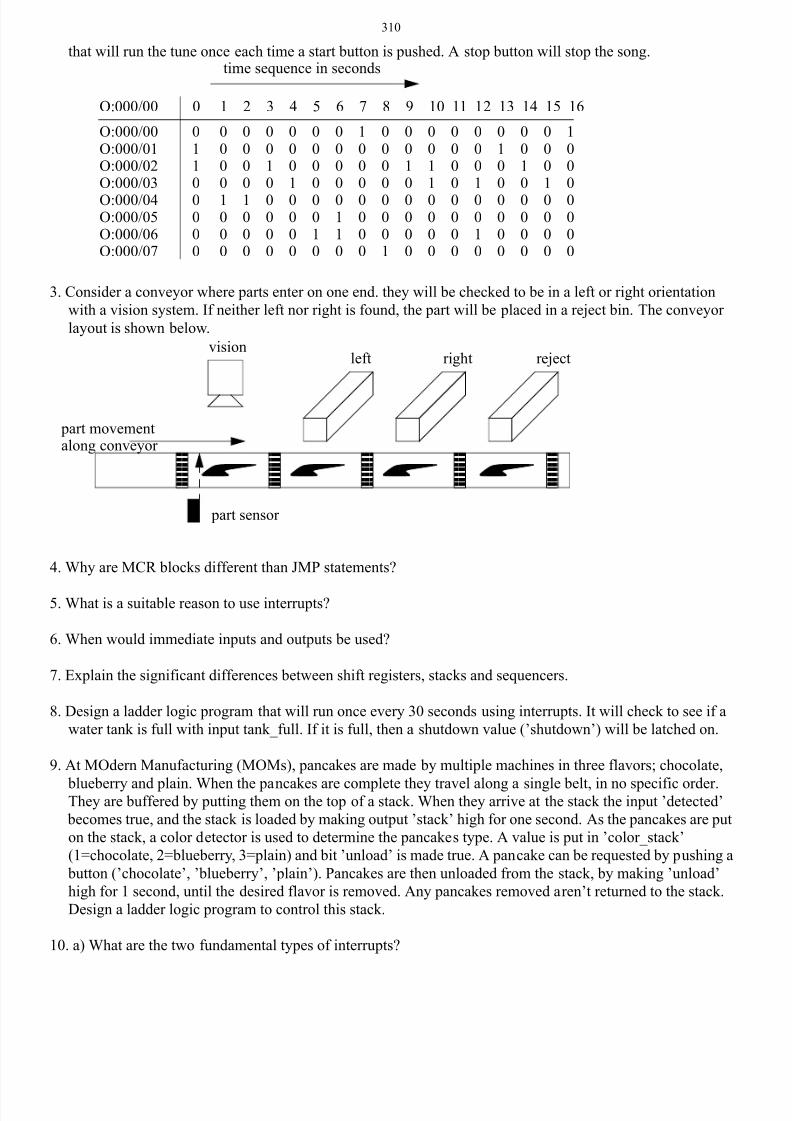
2. A PLC is to be used to control a carillon (a bell tower). Each bell corresponds to a musical note and each has
a pneumatic actuator that will ring it. The table below defines the tune to be programmed. Write a program
OUTPUTSO.0 NSG - north south greenO.1 NSY - north south yellowO.2 NSR - north south redO.3 EWG - east west greenO.4 EWY - east west yellow
O.5 EWR - east west red
TONt preset 4.0 sec
SQOFile n[0]mask 0x003F
t.DN
t.DN
Dest. OControl cLength 10
Addr.
n[0]
n[1]
n[2]
n[3]
n[4]
n[5]
n[6]
n[7]n[8]
n[9]
n[10]
Contents (in binary)
0000000000001001
0000000000100001
0000000000100001
0000000000100001
0000000000100001
0000000000100010
0000000000001100
00000000000011000000000000001100
0000000000001100
0000000000010100
8/6/2019 Plc Adv Func
http://slidepdf.com/reader/full/plc-adv-func 24/28
310
that will run the tune once each time a start button is pushed. A stop button will stop the song.
3. Consider a conveyor where parts enter on one end. they will be checked to be in a left or right orientation
with a vision system. If neither left nor right is found, the part will be placed in a reject bin. The conveyor
layout is shown below.
4. Why are MCR blocks different than JMP statements?
5. What is a suitable reason to use interrupts?
6. When would immediate inputs and outputs be used?
7. Explain the significant differences between shift registers, stacks and sequencers.
8. Design a ladder logic program that will run once every 30 seconds using interrupts. It will check to see if a
water tank is full with input tank_full. If it is full, then a shutdown value (’shutdown’) will be latched on.
9. At MOdern Manufacturing (MOMs), pancakes are made by multiple machines in three flavors; chocolate,
blueberry and plain. When the pancakes are complete they travel along a single belt, in no specific order.They are buffered by putting them on the top of a stack. When they arrive at the stack the input ’detected’
becomes true, and the stack is loaded by making output ’stack’ high for one second. As the pancakes are put
on the stack, a color detector is used to determine the pancakes type. A value is put in ’color_stack’
(1=chocolate, 2=blueberry, 3=plain) and bit ’unload’ is made true. A pancake can be requested by pushing a
button (’chocolate’, ’blueberry’, ’plain’). Pancakes are then unloaded from the stack, by making ’unload’
high for 1 second, until the desired flavor is removed. Any pancakes removed aren’t returned to the stack.
Design a ladder logic program to control this stack.
10. a) What are the two fundamental types of interrupts?
O:000/00O:000/01O:000/02O:000/03
O:000/04O:000/05O:000/06O:000/07
0110
0000
0000
1000
0000
1000
0010
0000
0001
0000
0000
0010
0000
0110
1000
0000
0000
0001
0010
0000
0011
0000
0000
0000
0001
0010
0100
0000
0010
0000
0001
0000
1000
0000
O:000/00 0 1 2 3 4 5 6 7 8 9 10 11 12 13 14 15 16
time sequence in seconds
visionleft right reject
part movement
part sensor
along conveyor
8/6/2019 Plc Adv Func
http://slidepdf.com/reader/full/plc-adv-func 25/28
311
b) What are the advantages of interrupts in control programs?
c) What potential problems can they create?
d) Which instructions can prevent this problem?
11. Write a ladder logic program to drive a set of flashing lights. In total there are 10 lights connected to
’lights[0]’ to ’lights[9]’. At any time every one out of three lights should be on. Every second the pattern on
the lights should shift towards ’lights[9]’.
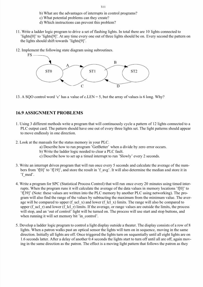
12. Implement the following state diagram using subroutines.
13. A SQO control word ‘c’ has a value of c.LEN = 5, but the array of values is 6 long. Why?
16.9 ASSIGNMENT PROBLEMS
1. Using 3 different methods write a program that will continuously cycle a pattern of 12 lights connected to a
PLC output card. The pattern should have one out of every three lights set. The light patterns should appear
to move endlessly in one direction.
2. Look at the manuals for the status memory in your PLC.
a) Describe how to run program ’GetBetter’ when a divide by zero error occurs.
b) Write the ladder logic needed to clear a PLC fault.c) Describe how to set up a timed interrupt to run ’Slowly’ every 2 seconds.
3. Write an interrupt driven program that will run once every 5 seconds and calculate the average of the num-
bers from ’f[0]’ to ’f[19]’, and store the result in ’f_avg’. It will also determine the median and store it in
’f_med’.
4. Write a program for SPC (Statistical Process Control) that will run once every 20 minutes using timed inter-
rupts. When the program runs it will calculate the average of the data values in memory locations ’f[0]’ to
’f[39]’ (Note: these values are written into the PLC memory by another PLC using networking). The pro-
gram will also find the range of the values by subtracting the maximum from the minimum value. The aver-
age will be compared to upper (f_ucl_x) and lower (f_lcl_x) limits. The range will also be compared toupper (f_ucl_r) and lower (f_lcl_r) limits. If the average, or range values are outside the limits, the process
will stop, and an ‘out of control’ light will be turned on. The process will use start and stop buttons, and
when running it will set memory bit ’in_control’.
5. Develop a ladder logic program to control a light display outside a theater. The display consists of a row of 8
lights. When a patron walks past an optical sensor the lights will turn on in sequence, moving in the same
direction. Initially all lights are off. Once triggered the lights turn on sequentially until all eight lights are on
1.6 seconds latter. After a delay of another 0.4 seconds the lights start to turn off until all are off, again mov-
ing in the same direction as the patron. The effect is a moving light pattern that follows the patron as they
ST0 ST1 ST2
FS
AB
C D
8/6/2019 Plc Adv Func
http://slidepdf.com/reader/full/plc-adv-func 26/28
312
walk into the theater.
6. Write the ladder logic diagram that would be required to execute the following data manipulation for a pre-
ventative maintenance program.
i) Keep track of the number of times a motor was started with toggle switch #1.
ii) After 2000 motor starts turn on an indicator light on the operator panel.
iii) Provide the capability to change the number of motor starts being tracked, prior to triggering
of the indicator light. HINT: This capability will only require the change of a value in a com-
pare statement rather than the addition of new lines of logic.iv) Keep track of the number of minutes that the motor has run.
v) After 9000 minutes of operation turn the motor off automatically and also turn on an indica-
tor light on the operator panel.
7. Parts arrive at an oven on a conveyor belt and pass a barcode scanner. When the barcode scanner reads a
valid barcode it outputs the numeric code as 32 bits to ’scanner_value’ and sets input ’scanner_value_valid’.
The PLC must store this code until the parts pass through the oven. When the parts leave the oven they are
detected by a proximity sensor connected to ’part_leaving’. The barcode value read before must be output to
’barcode_output’. Write the ladder logic for the process. There can be up to ten parts inside the oven at any
time.
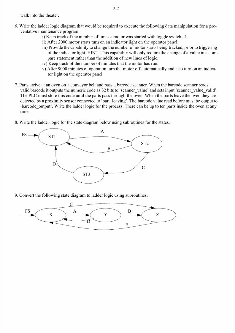
8. Write the ladder logic for the state diagram below using subroutines for the states.
9. Convert the following state diagram to ladder logic using subroutines.
ST1
ST2
ST3
A
B
CD
FS
FS A B
C
DE
X Y Z
8/6/2019 Plc Adv Func
http://slidepdf.com/reader/full/plc-adv-func 27/28
313
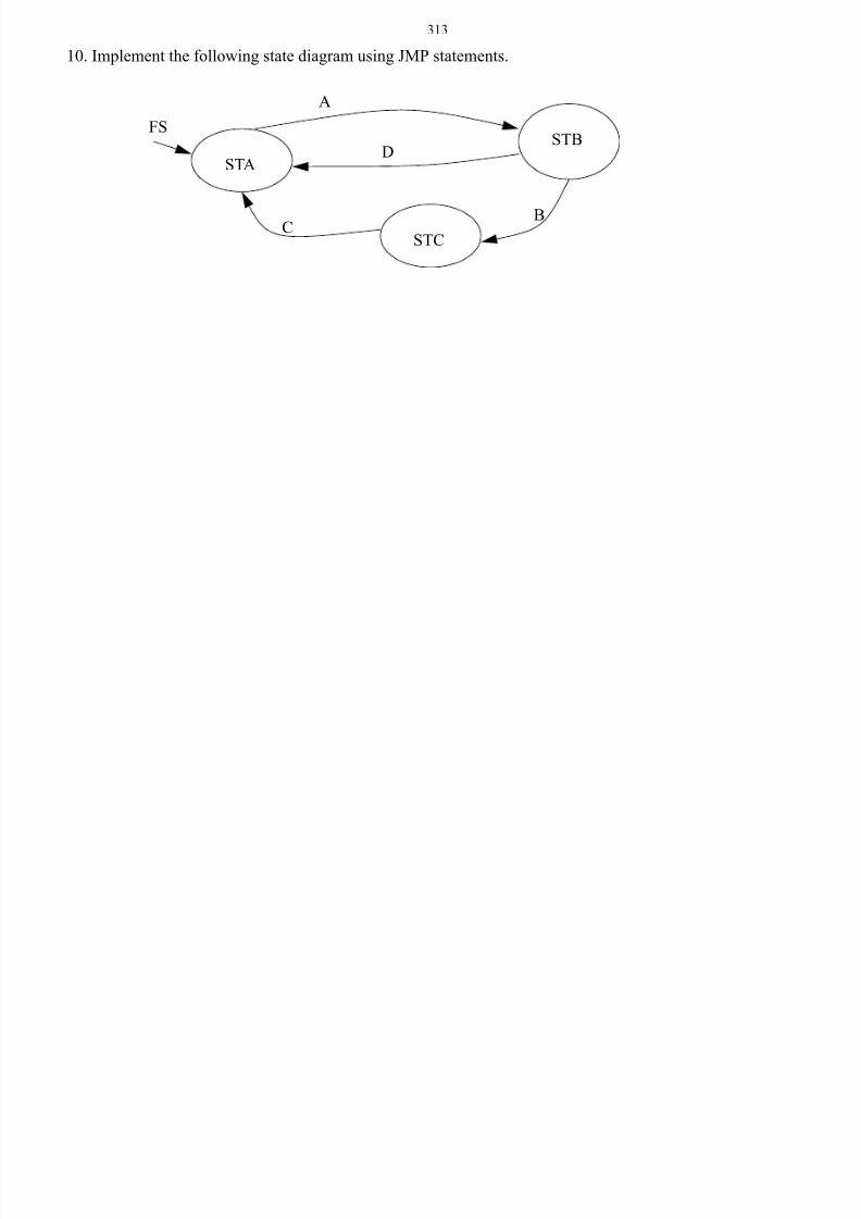
10. Implement the following state diagram using JMP statements.
FS
STA
STB
STC
A
BC
D

8/6/2019 Plc Adv Func
http://slidepdf.com/reader/full/plc-adv-func 28/28
314