Embed Size (px)
Citation preview
40
PLGPLG
SER
IE
Der Leise
PLG - SERIEStHe siLent
Dieses hoch robuste Linearführungssystem in den Baureihen PLG 16 – 63 wurde speziell für die Anwendung Werkzeugma-schinen und Industrierobotertechnik entwickelt.Als Antriebsele ment kommt unser bewährter kolbenstangenloser Zylinder in den Ø-Reihen 16 – 63 mm zum Einsatz.
This extremely robust linearsystem from the series PLG 16 – 63 has been especially developed for use in the machine tool and robototics industries.The move force for this guide is our proven rodless cylinder Ø 16 – 63 mm.
41
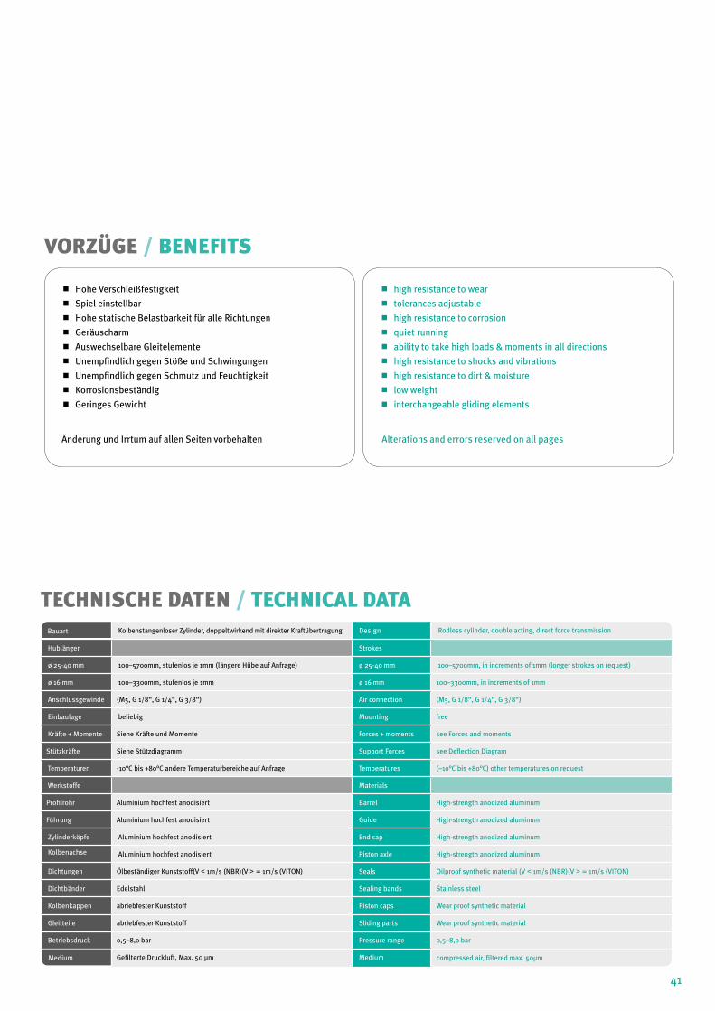
Hohe Verschleißfestigkeit
Spiel einstellbar
Hohe statische Belastbarkeit für alle Richtungen
Geräuscharm
Auswechselbare Gleitelemente
Unempfindlich gegen Stöße und Schwingungen
Unempfindlich gegen Schmutz und Feuchtigkeit
Korrosionsbeständig
Geringes Gewicht
Änderung und Irrtum auf allen Seiten vorbehalten
high resistance to wear
tolerances adjustable
high resistance to corrosion
quiet running
ability to take high loads & moments in all directions
high resistance to shocks and vibrations
high resistance to dirt & moisture
low weight
interchangeable gliding elements
Alterations and errors reserved on all pages
vORZÜGE / BENEFITS
TECHNISCHE DATEN / TECHNICAL DATABauart Kolbenstangenloser Zylinder, doppeltwirkend mit direkter Kraftübertragung Design Rodless cylinder, double acting, direct force transmission
Hublängen Strokes
ø 25-40 mm 100–5700mm, stufenlos je 1mm (längere Hübe auf Anfrage) ø 25-40 mm 100–5700mm, in increments of 1mm (longer strokes on request)
ø 16 mm 100–3300mm, stufenlos je 1mm ø 16 mm 100–3300mm, in increments of 1mm
Anschlussgewinde (M5, G 1/8“, G 1/4“, G 3/8“) Air connection (M5, G 1/8“, G 1/4“, G 3/8“)
Einbaulage beliebig Mounting free
Kräfte + Momente Siehe Kräfte und Momente Forces + moments see Forces and moments
Stützkräfte Siehe Stützdiagramm Support Forces see Deflection Diagram
Temperaturen -10°C bis +80°C andere Temperaturbereiche auf Anfrage Temperatures (–10°C bis +80°C) other temperatures on request
Werkstoffe Materials
Profilrohr Aluminium hochfest anodisiert Barrel High-strength anodized aluminum
Führung Aluminium hochfest anodisiert Guide High-strength anodized aluminum
Zylinderköpfe Aluminium hochfest anodisiert End cap High-strength anodized aluminum
Kolbenachse Aluminium hochfest anodisiert Piston axle High-strength anodized aluminum
Dichtungen Ölbeständiger Kunststoff(V < 1m/s (NBR)(V > = 1m/s (VITON) Seals Oilproof synthetic material (V < 1m/s (NBR)(V > = 1m/s (VITON)
Dichtbänder Edelstahl Sealing bands Stainless steel
Kolbenkappen abriebfester Kunststoff Piston caps Wear proof synthetic material
Gleitteile abriebfester Kunststoff Sliding parts Wear proof synthetic material
Betriebsdruck 0,5–8,0 bar Pressure range 0,5–8,0 bar
Medium Gefilterte Druckluft, Max. 50 µm Medium compressed air, filtered max. 50µm
42
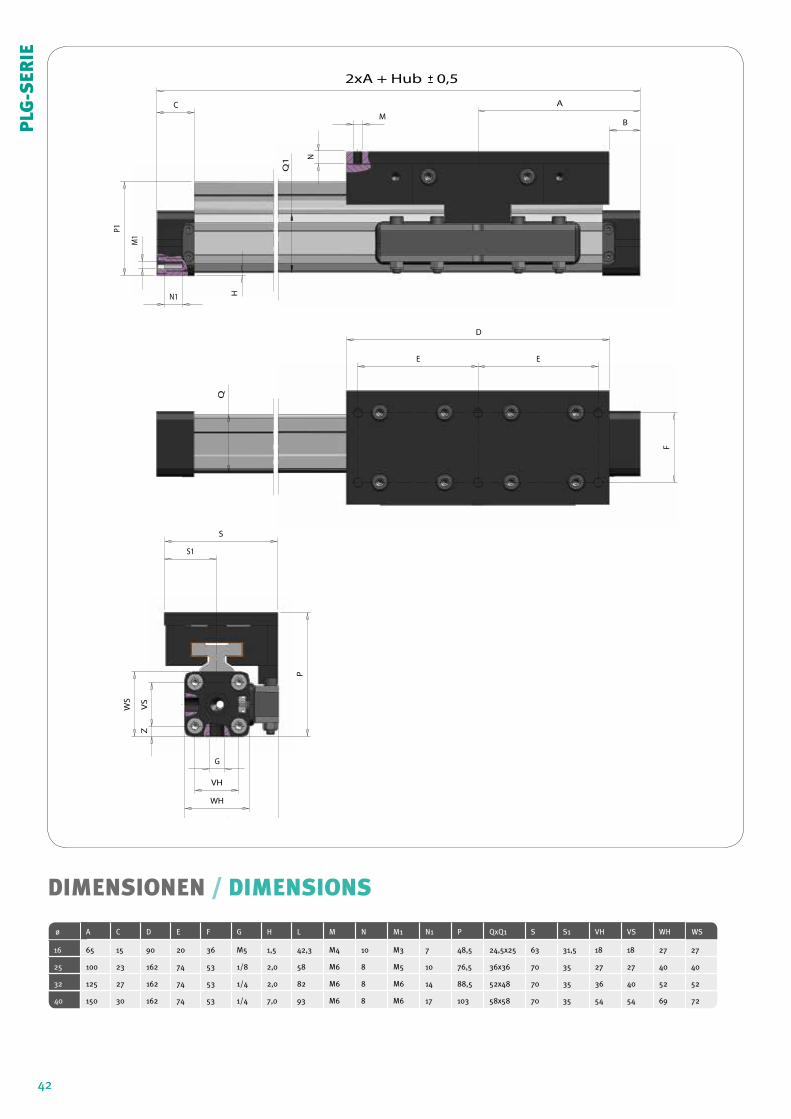
DIMENSIONEN / DIMENSIONS
ø A C D E F G H L M N M1 N1 P QxQ1 S S1 VH VS WH WS
16 65 15 90 20 36 M5 1,5 42,3 M4 10 M3 7 48,5 24,5x25 63 31,5 18 18 27 27
25 100 23 162 74 53 1/8 2,0 58 M6 8 M5 10 76,5 36x36 70 35 27 27 40 40
32 125 27 162 74 53 1/4 2,0 82 M6 8 M6 14 88,5 52x48 70 35 36 40 52 52
40 150 30 162 74 53 1/4 7,0 93 M6 8 M6 17 103 58x58 70 35 54 54 69 72
B
S
P
VH
VS
Z
F
S1
G
WH
L
WS
B
C
VH
VS
Z
F
E E
S1A
D
P1
H
WH
L
WS
Q
M
NN1
M1
Q1
2xA + Hub 0,5
PLG
-SER
IE
43
L
Mv
Ma
Mr
F
ha
y
hr hv
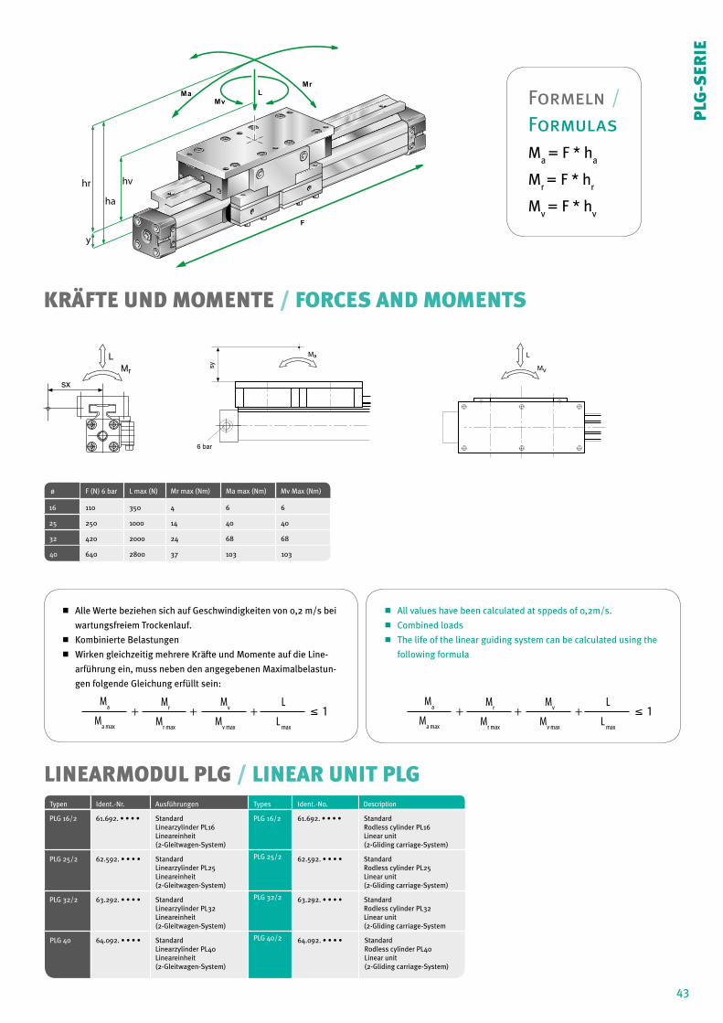
Alle Werte beziehen sich auf Geschwindigkeiten von 0,2 m/s bei
wartungsfreiem Trockenlauf.
Kombinierte Belastungen
Wirken gleichzeitig mehrere Kräfte und Momente auf die Line-
arführung ein, muss neben den angegebenen Maximalbelastun-
gen folgende Gleichung erfüllt sein:
All values have been calculated at sppeds of 0,2m/s.
Combined loads
The life of the linear guiding system can be calculated using the
following formula
KRÄFTE UND MOMENTE / FORCES AND MOMENTS
LINEARMODUL PLG / LINEAR UNIT PLG
ø F (N) 6 bar L max (N) Mr max (Nm) Ma max (Nm) Mv Max (Nm)
16 110 350 4 6 6
25 250 1000 14 40 40
32 420 2000 24 68 68
40 640 2800 37 103 103
Typen Ident.-Nr. Ausführungen Types Ident.-No. Description
PLG 16/2 61.692. • • • • StandardLinearzylinder PL16Lineareinheit(2-Gleitwagen-System)
PLG 16/2 61.692. • • • • StandardRodless cylinder PL16Linear unit(2-Gliding carriage-System)
PLG 25/2 62.592. • • • • StandardLinearzylinder PL25Lineareinheit(2-Gleitwagen-System)
PLG 25/2 62.592. • • • • StandardRodless cylinder PL25Linear unit(2-Gliding carriage-System)
PLG 32/2 63.292. • • • • StandardLinearzylinder PL32Lineareinheit(2-Gleitwagen-System)
PLG 32/2 63.292. • • • • StandardRodless cylinder PL32Linear unit(2-Gliding carriage-System
PLG 40 64.092. • • • • StandardLinearzylinder PL40Lineareinheit(2-Gleitwagen-System)
PLG 40/2 64.092. • • • • StandardRodless cylinder PL40Linear unit(2-Gliding carriage-System)
MrL
sx
Ma
6 bar
sy
L
Mv
Ma
Ma max
+ + + 1 Mr
Mr max
Mv
Mv max
L
L max
PLG
-SER
IEMa
Ma max
+ + + 1 Mr
Mr max
Mv
Mv max
L
L max
Formeln / FormulasM
a = F * h
a
Mr = F * h
r
Mv = F * h
v