Embed Size (px)
Citation preview
1
Stefanie DietrichPraktikum Plus
Allmend Hütte Project
2
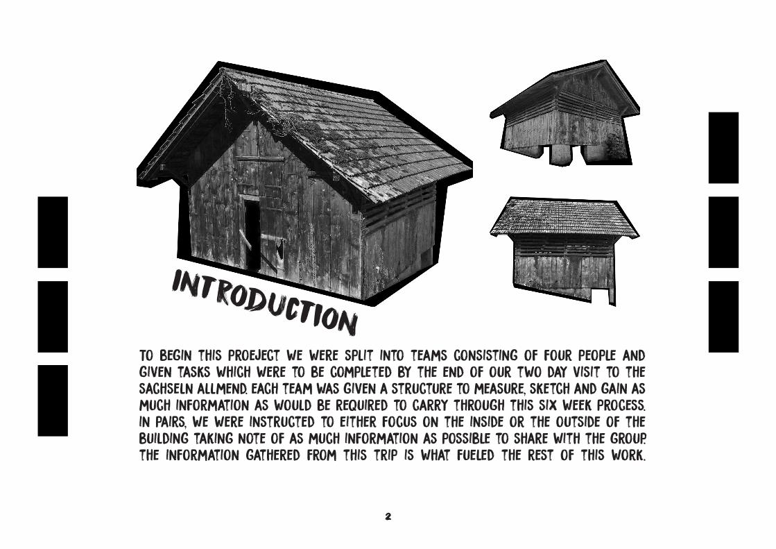
IntroductionTo begin this proeject we were split into teams consisting of four people and given tasks which were to be completed by the end of our two day visit to the sachseln allmend. each team was given a structure to measure, sketch and gain as much information as would be required to carry through this six week process. in pairs, we were instructed to either focus on the inside or the outside of the building taking note of as much information as possible to share with the group. the information gathered from this trip is what fueled the rest of this work.
3
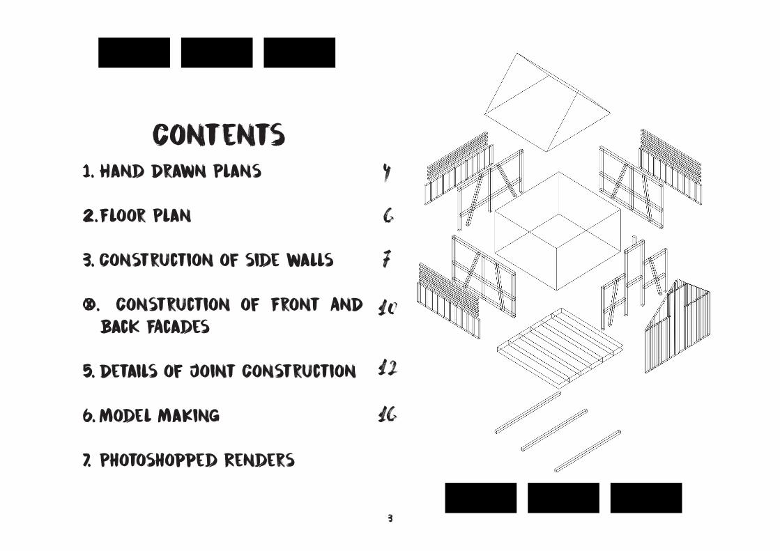
Contents1. Hand Drawn Plans
2. Floor Plan
3. Construction of side walls
4. Construction of Front AnD
Back FAcades
5. Details of Joint Construction
6. Model MaKing
7. Photoshopped Renders
4
6
7
10
12
16
4
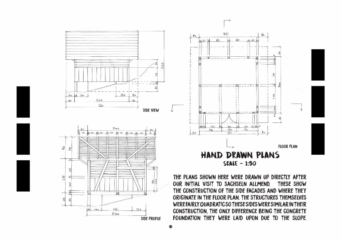
Hand Drawn PlansScale - 1:50
The plans shown here were drawn up directly after our initial visit to sachseln allmend. these show the construction of the side facades and where they originate in the floor plan. the structures themselves were fairly quadratic so these sides were similar in their construction, the only difference being the concrete foundation they were laid upon due to the slope.
Side View
Side Profile
Floor Plan
5
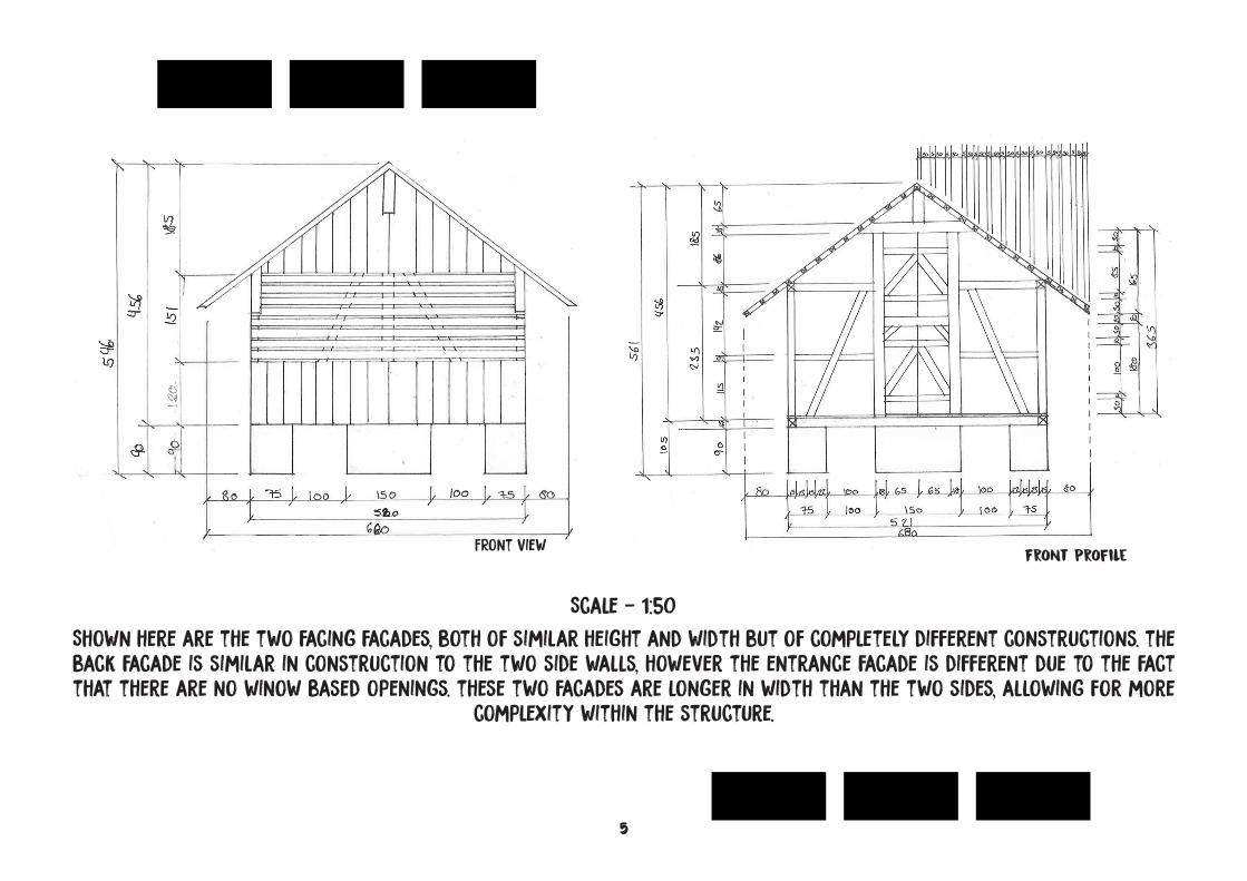
Shown here are the two facing facades, both of similar height and width but of completely different constructions. the back facade is similar in construction to the two side walls, however the entrance facade is different due to the fact that there are no winow based openings. these two facades are longer in width than the two sides, allowing for more
complexity within the structure.
FRont View Front Profile
Scale - 1:50
6
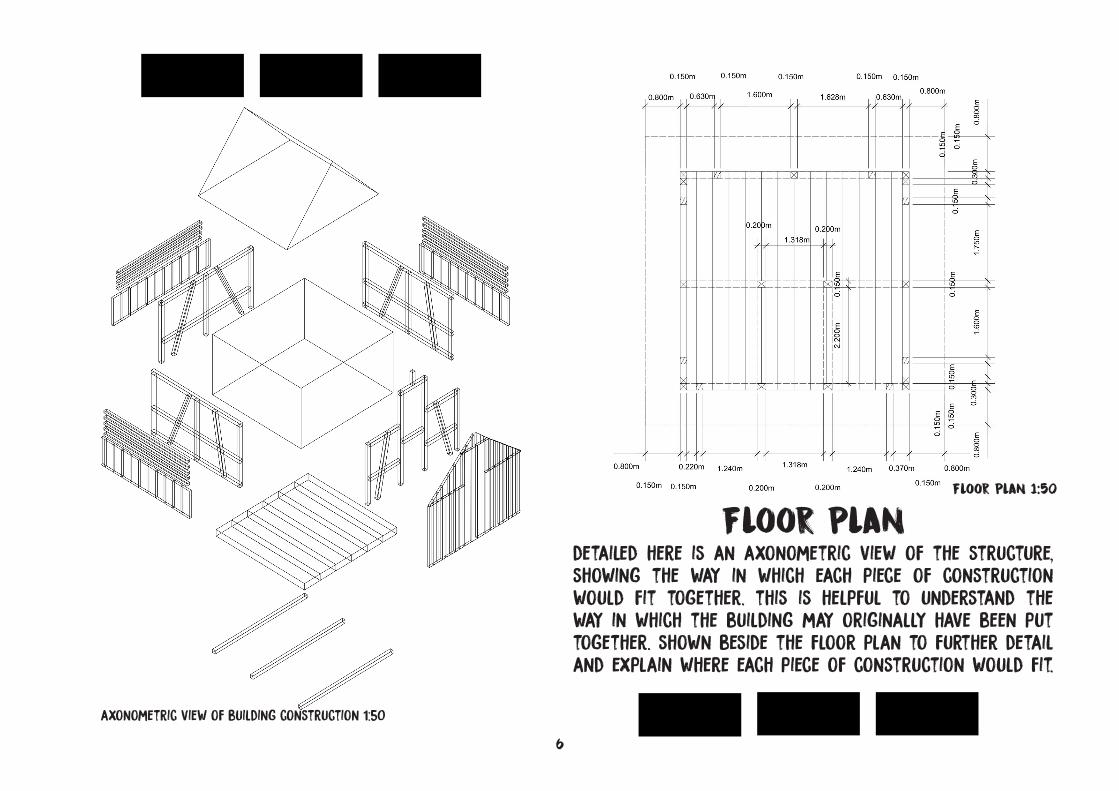
detailed here is an axonometric view of the structure, showing the way in which each piece of construction would fit together. this is helpful to understand the way in which the building may originally have been put together. shown beside the floor plan to further detail and explain where each piece of construction would fit.
Floor Plan
axonometric view of building construction 1:50
Floor Plan 1:50
7
0.120m
0.175m
0.060m
0.120m
0.085m
0.071m
0.120m
0.700m
0.120m
6.600m
1.714m
1.366m
1.660m
1.040m
1.890m
0.150m
0.890m
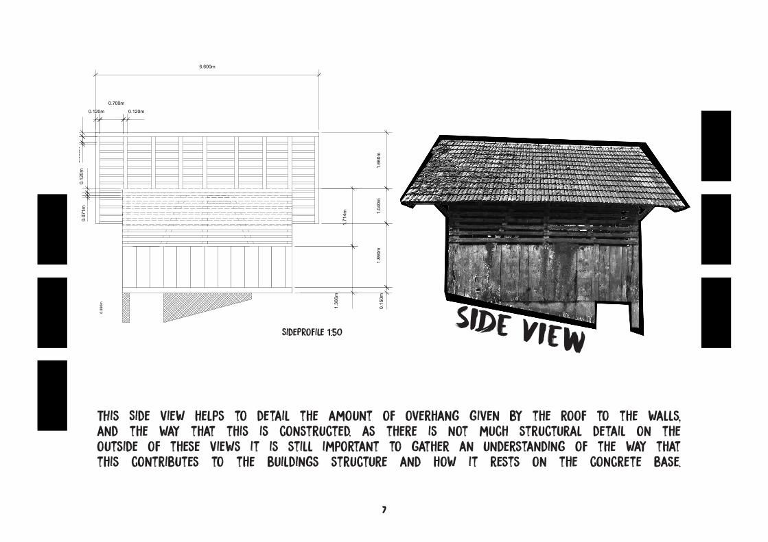
THis Side view helps to detail the amount of overhang given by the roof to the walls, and the way that this is constructed. as there is not much structural detail on the outside of these views it is still important to gather an understanding of the way that this contributes to the buildings structure and how it rests on the concrete base.
Side ViewSidePRofile 1:50
8
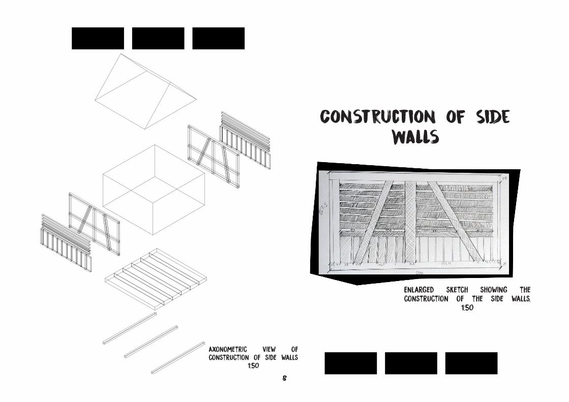
Construction of Side Walls
Axonometric view of construction of side walls
1:50
Enlarged sketch showing the construction of the side walls.
1:50
9
15
15
1.456
163
431
15
572
163
1.465
15
15
69
1.035
15
315
12
1.505
91.035
15
3155.00
2.90
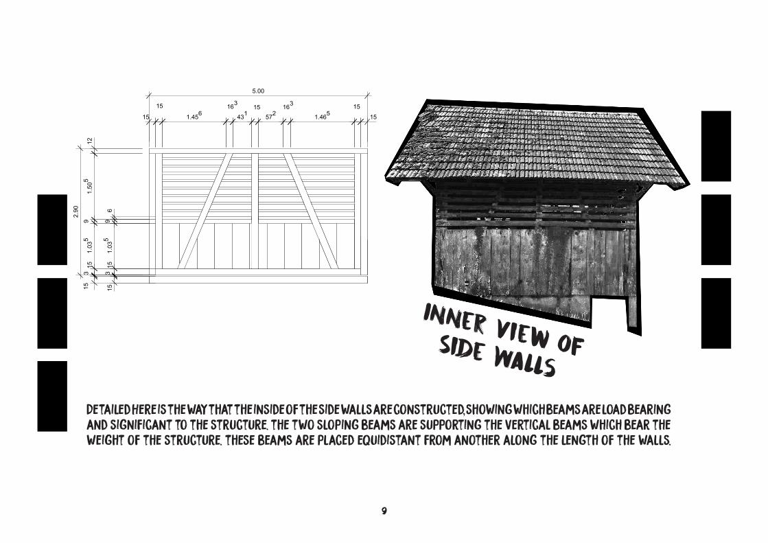
Inner View of Side WallsDetailed Here is the way that the inside of the side walls are constructed, showing which beams are load bearing and significant to the structure. the two sloping beams are supporting the vertical beams which bear the weight of the structure. these beams are placed equidistant from another along the length of the walls.
10
75 1.00 1.738
1.00 75 80
1.522
1.26
10
20
90
4.156
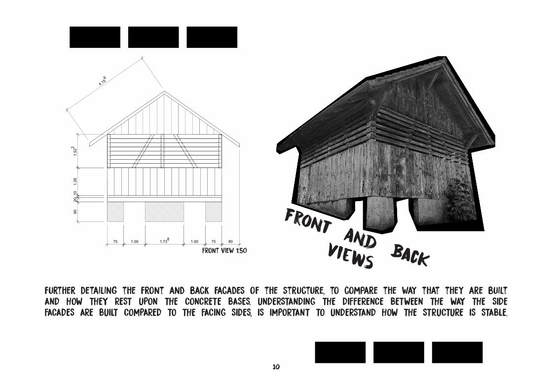
Front And Back Views
further detailing the front and back facades of the structure, to compare the way that they are built AND HOW THEY REST UPON THE CONCRETE BASES. UNDERSTANDING THE DIFFERENCE BETWEEN THE WAY THE SIDE FACADES ARE BUILT COMPARED TO THE FACING SIDES, IS IMPORTANT TO UNDERSTAND HOW THE STRUCTURE IS STABLE.
FRont View 1:50
11
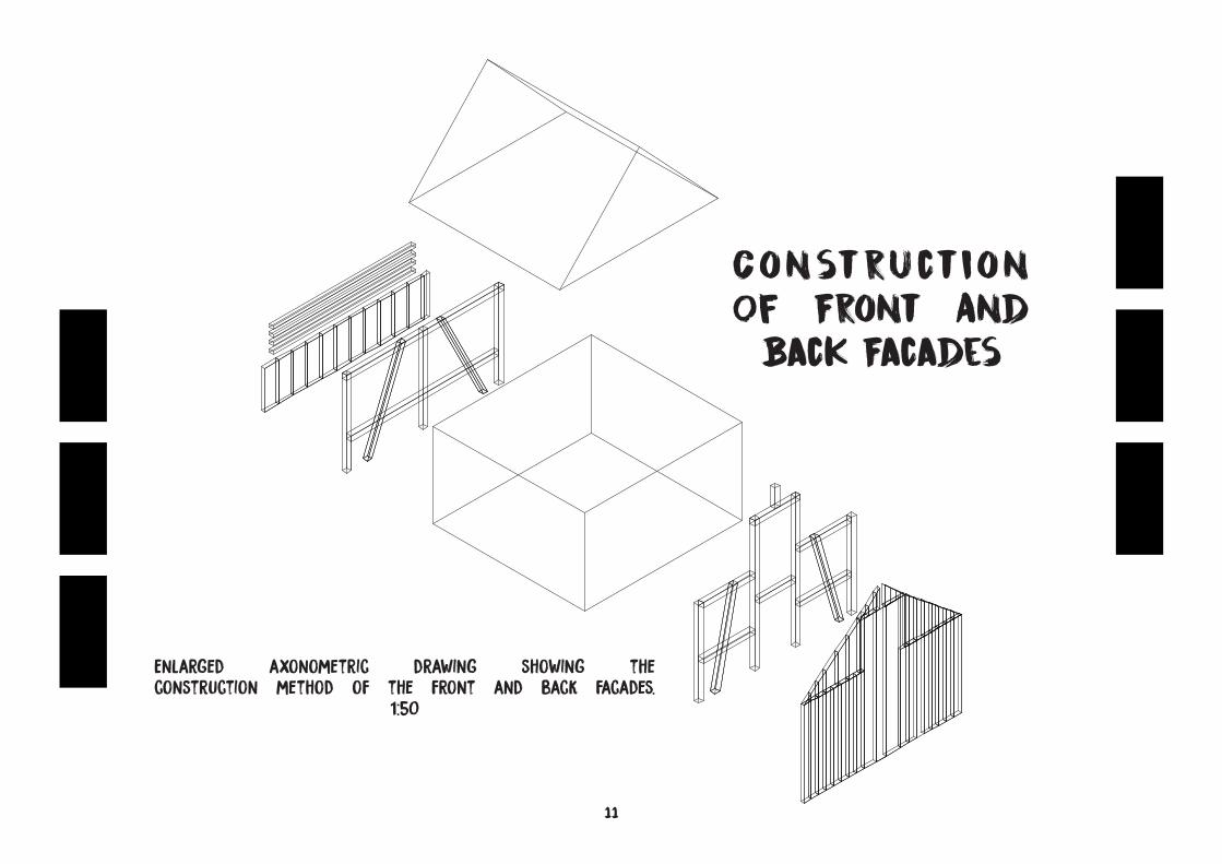
Construction Of Front And
Back Facades
Enlarged axonometric drawing showing the construction method of the front and back facades.
1:50
12
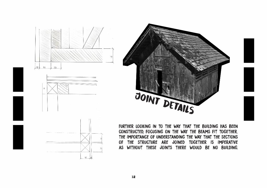
Joint DetailsFurther looking in to the way that the building has been constructed, focusing on the way the beams fit together. the importance of understanding the way that the sections of the structure are joined together is imperative as without these joints there would be no building.
13
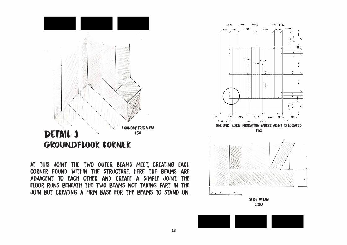
Detail 1GRoundFloor corner
At this joint the two outer beams meet, creating each corner found within the structure. here the beams are adjacent to each other and create a simple joint. the floor runs beneath the two beams not taking part in the join but creating a firm base for the beams to stand on.
Axonometric view1:50
Ground Floor indicating where joint is located1:50
Side view1:50
1475 1.00 1.73
81.00 75 80
1.522
1.26
10
20
90
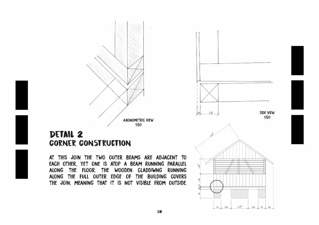
4.156Detail 2
Corner Construction
at this join the two outer beams are adjacent to each other, yet one is atop a beam running parallel along the floor. the wooden claddiWng running along the full outer edge of the building covers the join, meaning that it is not visible from outside.
Axonometric View1:50
Side View1:50
1575 1.00 1.73
81.00 75 80
1.522
1.26
10
20
90
4.156
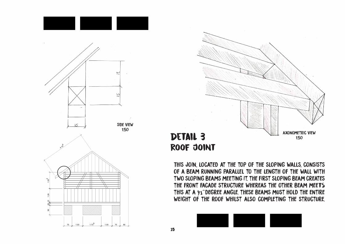
Detail 3Roof Joint
This join, located at the top of the sloping walls, consists of a beam running parallel to the length of the wall with two sloping beams meeting it. the first sloping beam creates the front facade structure whereas the other beam meets this at a 45 degree angle. these beams must hold the entire weight of the roof whilst also completing the structure.
axonometric View1:50
Side View1:50
16
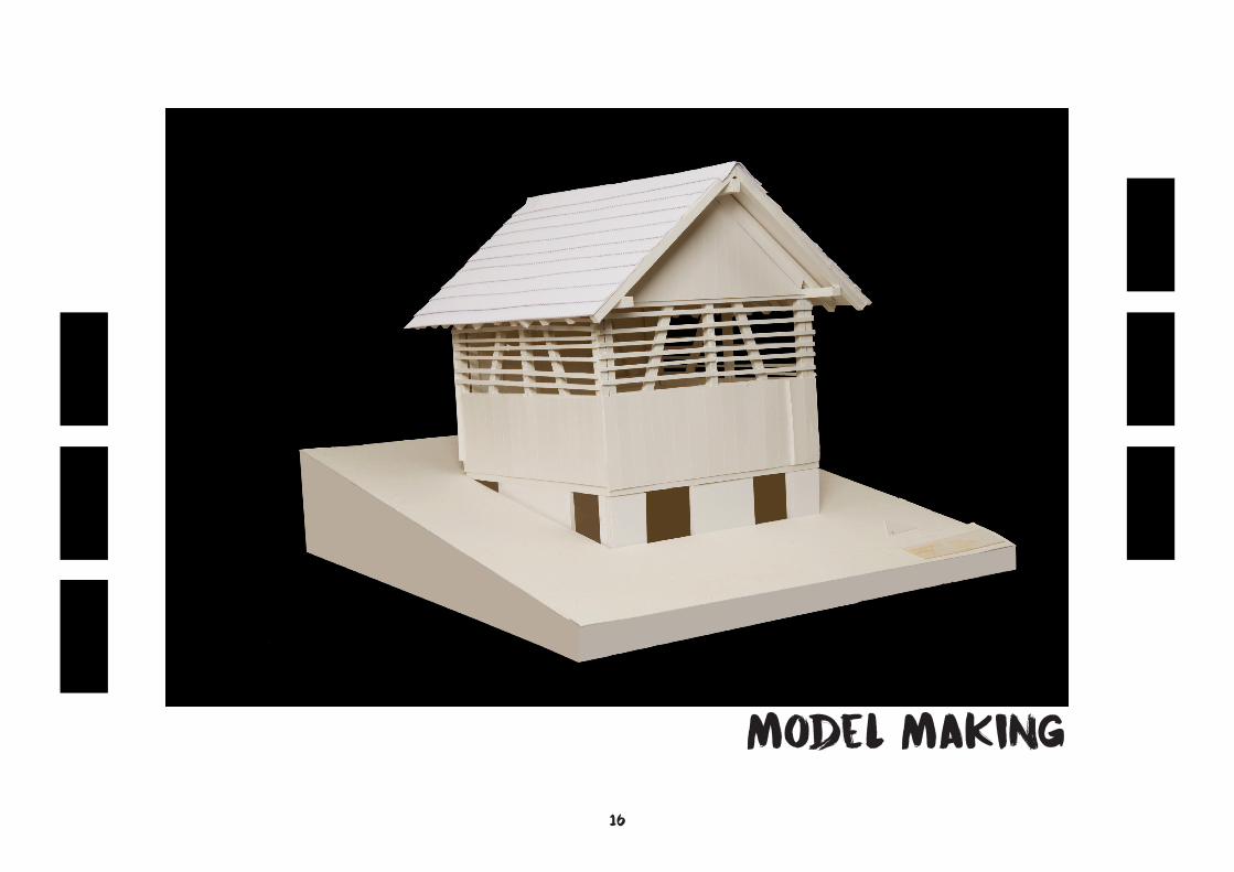
Model Making
17
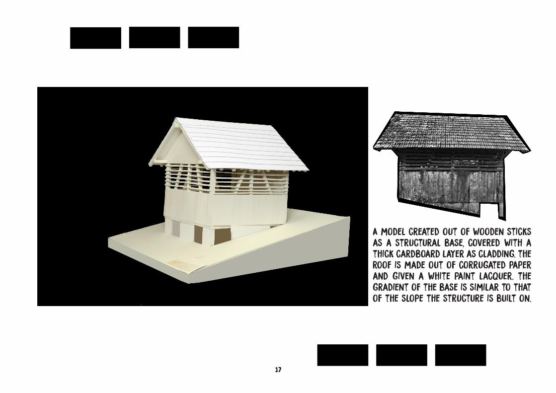
A model created out of wooden sticks as a structural base, covered with a thick cardboard layer as cladding. the roof is made out of corrugated paper and given a white paint lacquer. the gradient of the base is similar to that of the slope the structure is built on.
18
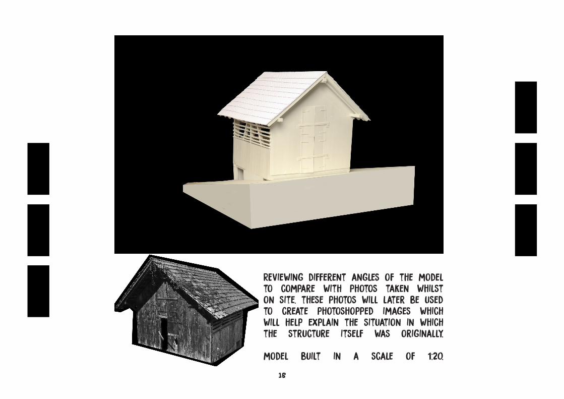
REviewing different angles of the model to compare with photos taken whilst on site. these photos will later be used to create photoshopped images which will help explain the situation in which the structure itself was originally.
model built in a scale of 1:20.
19
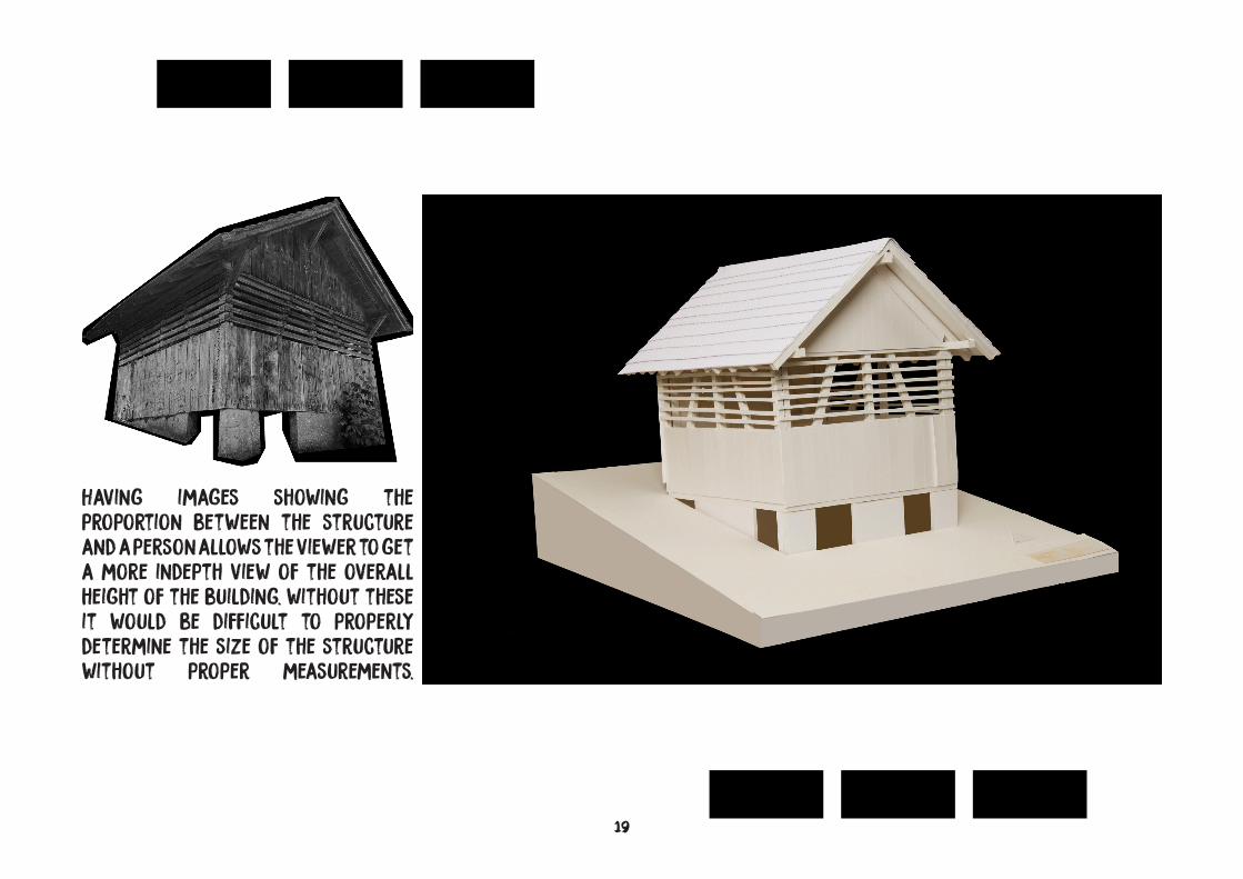
Having images showing the proportion between the structure and a person allows the viewer to get a more indepth view of the overall height of the building. without these it would be difficult to properly determine the size of the structure without proper measurements.
20
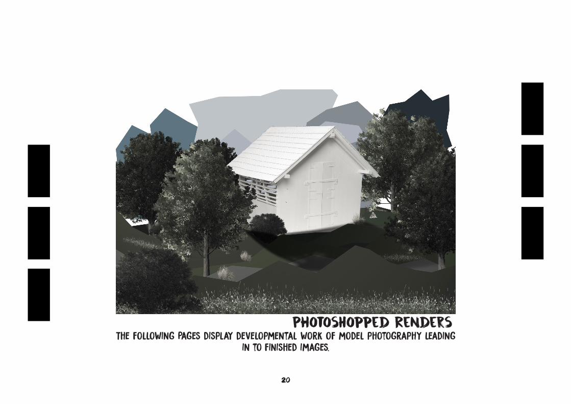
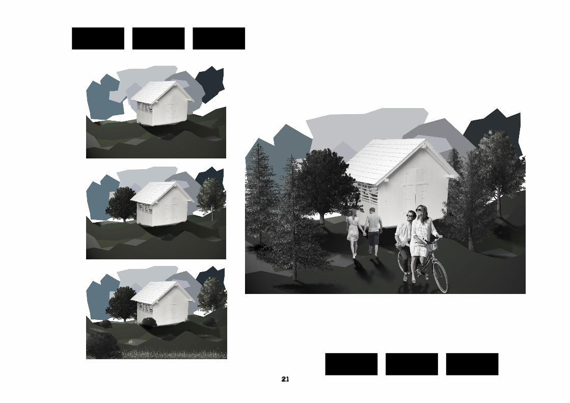
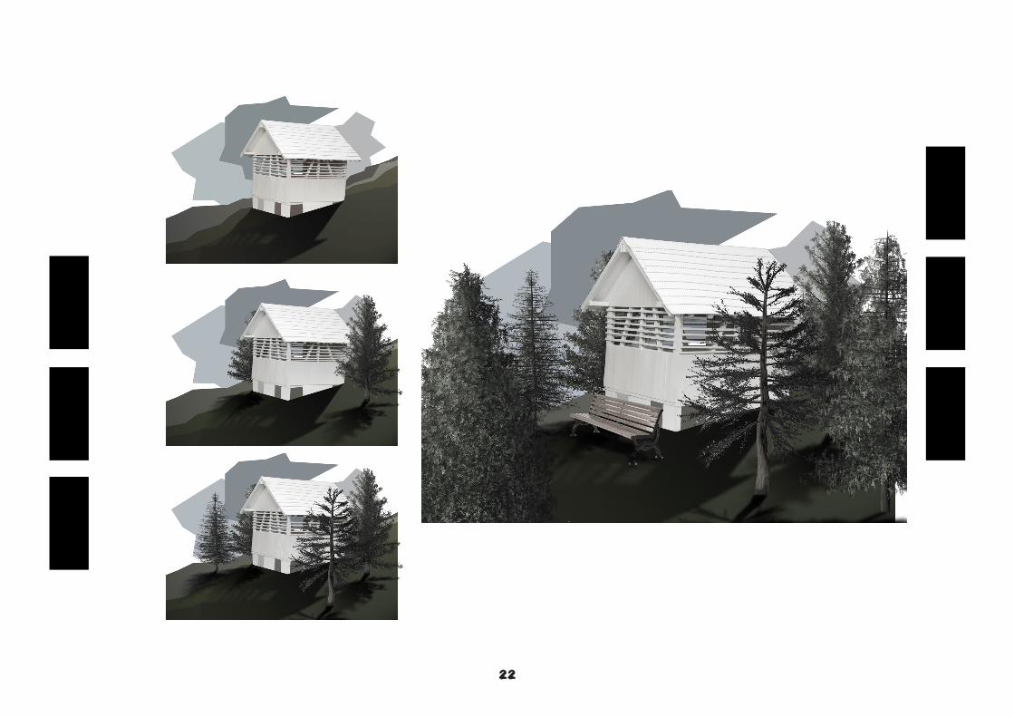
PHotoshopped RendersThe following Pages display developmental work of model photography leading
in to finished images.
21
22
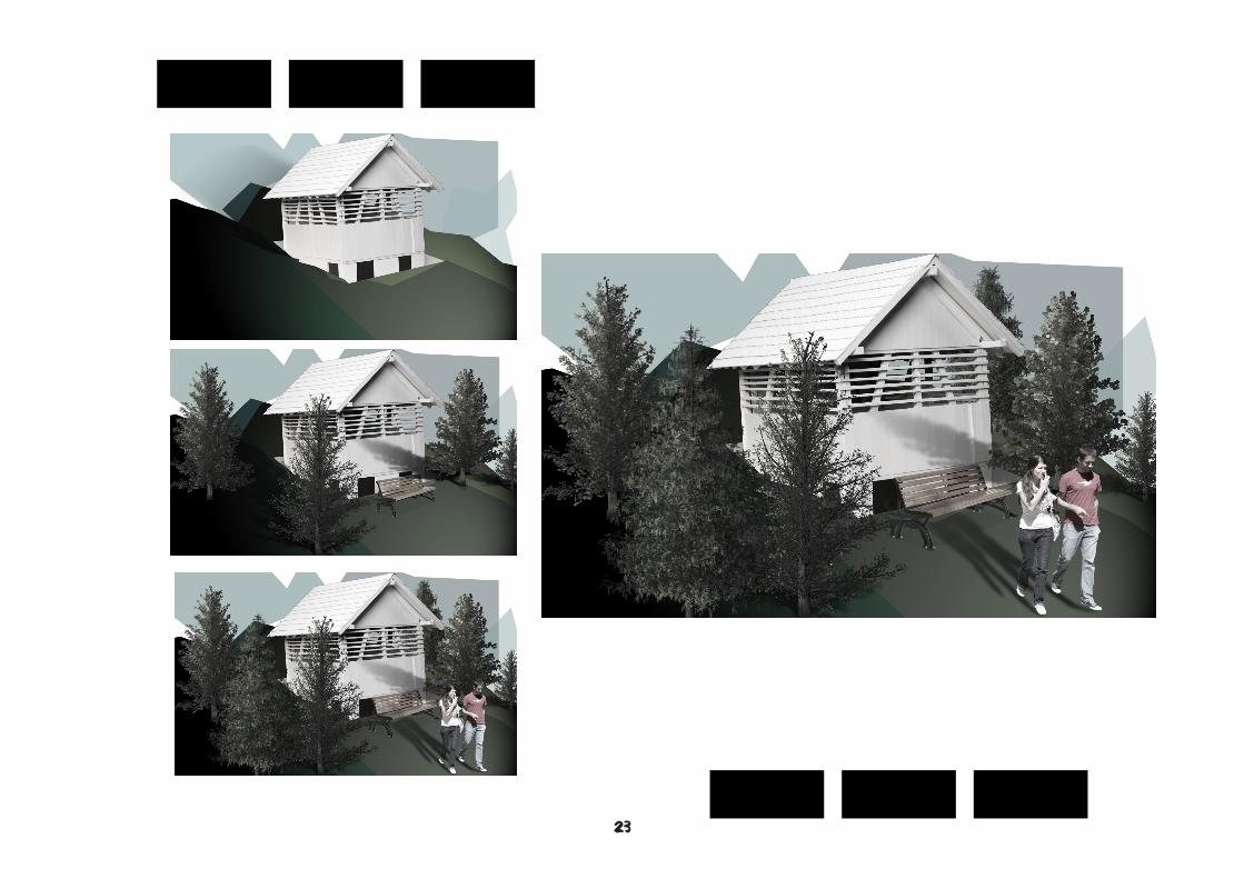
23
24
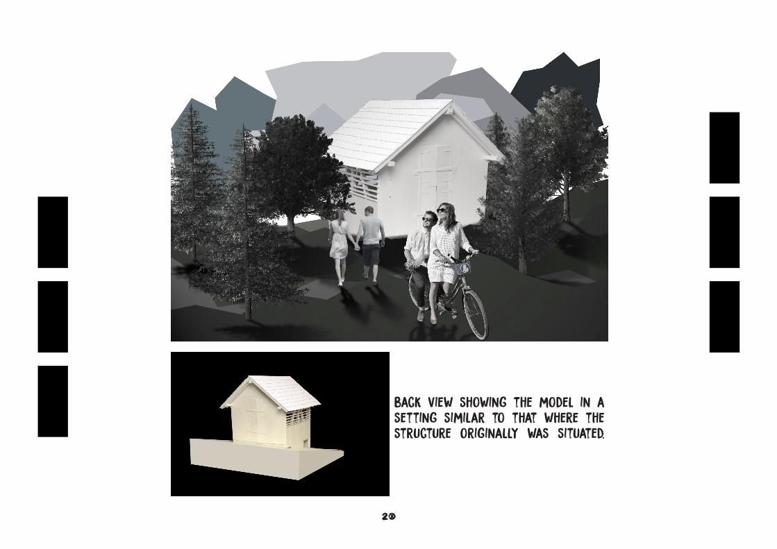
back view showing the model in a setting similar to that where the structure originally was situated.
25
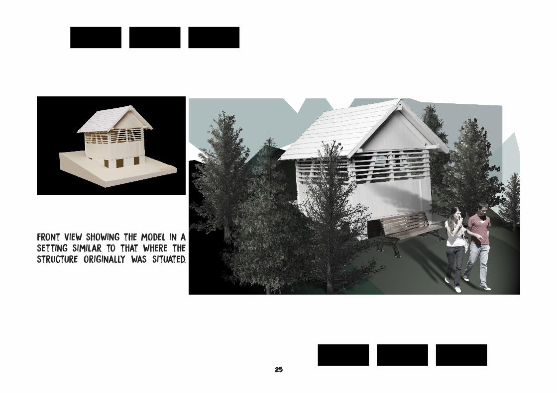
front view showing the model in a setting similar to that where the structure originally was situated.
26
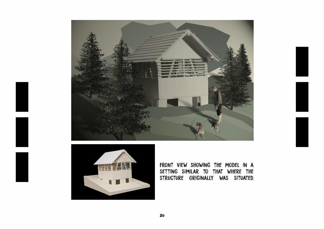
front view showing the model in a setting similar to that where the structure originally was situated.
27
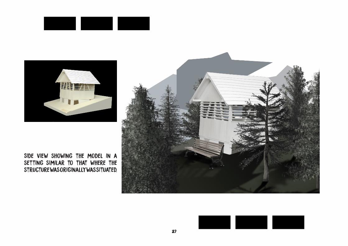
Side view showing the model in a setting similar to that where the structure was originally was situated.