Embed Size (px)
Citation preview
7/21/2019 posicao eletrodos tdcs
http://slidepdf.com/reader/full/posicao-eletrodos-tdcs 1/7
IOP PUBLISHING PHYSICS IN MEDICINE AND BIOLOGY
Phys. Med. Biol. 53 (2008) N219–N225 doi:10.1088/0031-9155/53/11/N03
NOTE
Determination of optimal electrode positions fortranscranial direct current stimulation (tDCS)
Chang-Hwan Im1, Hui-Hun Jung1, Jung-Do Choi1, Soo Yeol Lee2
and Ki-Young Jung3
1 Department of Biomedical Engineering, Yonsei University, Wonju, 220-710, Korea2 Department of Biomedical Engineering, Kyung Hee University, Suwon, Korea3 Korea University Medical Center, Korea University College of Medicine, Seoul, Korea
E-mail: [email protected]
Received 1 January 2008, in final form 28 April 2008Published 19 May 2008
Online at stacks.iop.org/PMB/53/N219
Abstract
The present study introduces a new approach to determining optimal electrode
positions in transcranial direct current stimulation (tDCS). Electric field and
3D conduction current density were analyzed using 3D finite element method
(FEM) formulated for a dc conduction problem. The electrode positions for
minimal current injection were optimized by changing the Cartesian coordinate
system into the spherical coordinate system and applying the (2+6) evolution
strategy (ES) algorithm. Preliminary simulation studies applied to a standard
three-layer head model demonstrated that the proposed approach is promising
in enhancing the performance of tDCS.
(Some figures in this article are in colour only in the electronic version)
1. Introduction
Transcranial direct current stimulation (tDCS) is a technique to stimulate the brain with
direct current (dc) generated at few (usually two) electrodes attached on the subject’s scalp
(Nitsche and Paulus 2000, Priori 2003, Holdefer et al 2006, Miranda et al 2006). Compared
to transcranial magnetic stimulation (TMS) (Salinas et al 2007, Miranda et al 2007), tDCS
stimulates relatively wide brain regions, but is thought to be appropriate for the stimulation of relatively deeperbrain areas than TMS, because themagneticinduction current elicited by TMS
is generally distributed at shallow cortical areas (Im and Lee 2006). tDCS has various potential
applications in areas such as depression (Fregni et al 2005), electro-analgesia (Mignon et al
1996), epilepsy (Fregni et al 2006) and so on (Fregni and Pascual-Leone 2007).
In the practical application of tDCS, the amplitude of the injection current should be
considered carefully because large injection current density near the electrodes may cause
side effects such as skin burn and muscle spasm. Moreover, it is obvious that excessive current
0031-9155/08/110219+07$30.00 © 2008 Institute of Physics and Engineering in Medicine Printed in the UK N219
7/21/2019 posicao eletrodos tdcs
http://slidepdf.com/reader/full/posicao-eletrodos-tdcs 2/7
N220 C-H Im et al
injection causes unnecessarily widespread brain activation. Considering these two aspects, it
is desirable to reduce the injection current to a minimal value, while maintaining the desired
amount of current at a target brain area. Since for a given head model the current density
distribution is influenced only by the scalp electrodes locations, injecting the minimal current
can be realized by optimizing the electrode locations. This problem is equivalent to a simplerproblem searching for two electrode locations which can generate maximum current flow at
the target brain area with a fixed injection current.
In the present study, the positions of the two scalp electrodes were optimized by
transforming the position parameters in a Cartesian coordinate system into angle parameters
in a spherical coordinate system and applying the (2+6) evolution strategy (ES) algorithm
(Im et al 2004). 3D finite element method (FEM) formulated for a dc conduction problem
was used for the electric field analysis (Jin 2002). We applied the proposed approach to two
case studies, for which a standard three-layer head model was used.
2. Methods and materials
2.1. Problem definition and finite element method (FEM)
Analysis of conduction current density is essential in the analysis of electrical stimulation
systems. Conventional studies have used a simplified head model (Miranda et al 2006) or a
single slice brain model (Holdefer et al 2006) for the numerical analysis of the 3D conduction
current. In the present study, full 3D analysis was performed using a 3D steady-state FEM
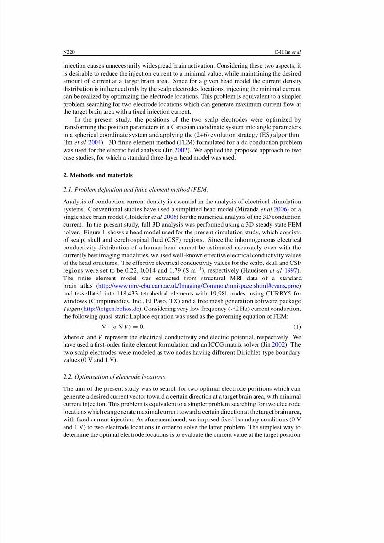
solver. Figure 1 shows a head model used for the present simulation study, which consists
of scalp, skull and cerebrospinal fluid (CSF) regions. Since the inhomogeneous electrical
conductivity distribution of a human head cannot be estimated accurately even with the
currently best imaging modalities, we used well-known effective electrical conductivity values
of the head structures. The effective electrical conductivity values for the scalp, skull and CSF
regions were set to be 0.22, 0.014 and 1.79 (S m −1), respectively (Haueisen et al 1997).
The finite element model was extracted from structural MRI data of a standard
brain atlas (http://www.mrc-cbu.cam.ac.uk/Imaging/Common/mnispace.shtml#evans proc)and tessellated into 118,433 tetrahedral elements with 19,981 nodes, using CURRY5 for
windows (Compumedics, Inc., El Paso, TX) and a free mesh generation software package
Tetgen (http://tetgen.belios.de). Considering very low frequency (<2 Hz) current conduction,
the following quasi-static Laplace equation was used as the governing equation of FEM:
∇ · (σ ∇ V ) = 0, (1)
where σ and V represent the electrical conductivity and electric potential, respectively. We
have used a first-order finite element formulation and an ICCG matrix solver (Jin 2002). The
two scalp electrodes were modeled as two nodes having different Dirichlet-type boundary
values (0 V and 1 V).
2.2. Optimization of electrode locations
The aim of the present study was to search for two optimal electrode positions which can
generate a desired current vector toward a certain direction at a target brain area, with minimal
current injection. This problem is equivalent to a simpler problem searching for two electrode
locations which can generate maximal current toward a certain direction at the target brain area,
with fixed current injection. As aforementioned, we imposed fixed boundary conditions (0 V
and 1 V) to two electrode locations in order to solve the latter problem. The simplest way to
determine the optimal electrode locations is to evaluate the current value at the target position
7/21/2019 posicao eletrodos tdcs
http://slidepdf.com/reader/full/posicao-eletrodos-tdcs 3/7
Determination of optimal electrode positions for tDCS N221
Figure 1. A finite element head model used for the present simulation study: the effectiveconductivity values for scalp, skull and CSF regions were set as 0.22, 0.014 and 1.79 (S m−1),respectively. The finite element model was extracted from structural MRI data of a standard brainatlas and tessellated into 118,433 tetrahedral elements and 19,981 nodes.
for the every possible combination of two nodes on the outmost boundary. Considering the
large number of boundary nodes (2342 nodes) and heavy computational cost of FEM, however,
such exhaustive scanning was not practical.
Inspired by the fact that the shape of the scalp surface can be roughly approximated as a
sphere, we transformed the location parameters in a Cartesian coordinate system into angle
parameters in a spherical coordinate system. First, the center of the head was approximately
determined by searching for the best-fitting sphere. Then, two angles in the spherical
coordinate (θ and ϕ) with respect to the center of the sphere were evaluated for every boundary
node. We used four angle parameters (θ 1, ϕ1), (θ 2, ϕ2), representing two scalp electrodes,
as the optimization variables. Once the four angle parameters had been determined during
the optimization processes, fixed boundary conditions (0 V and 1 V) were imposed at twoboundary nodes which have the most similar angle parameters. Then, the (2+6) evolution
strategy (ES) with an improved selection scheme was applied to the optimization (Im et al
2004). The population sizes 2 and 6 were determined empirically after some preliminary
simulations. The range of θ was set as (0◦, 120◦), in order to prevent electrodes from being
attached on the bottom of the head model. The range of ϕ was set as (0◦, 360◦). The ES
iteration continued until the quality of solutions was not improved any more or the mutation
range decreased to be smaller than a predetermined level (0.1% of the initial mutation range).
3. Simulation results
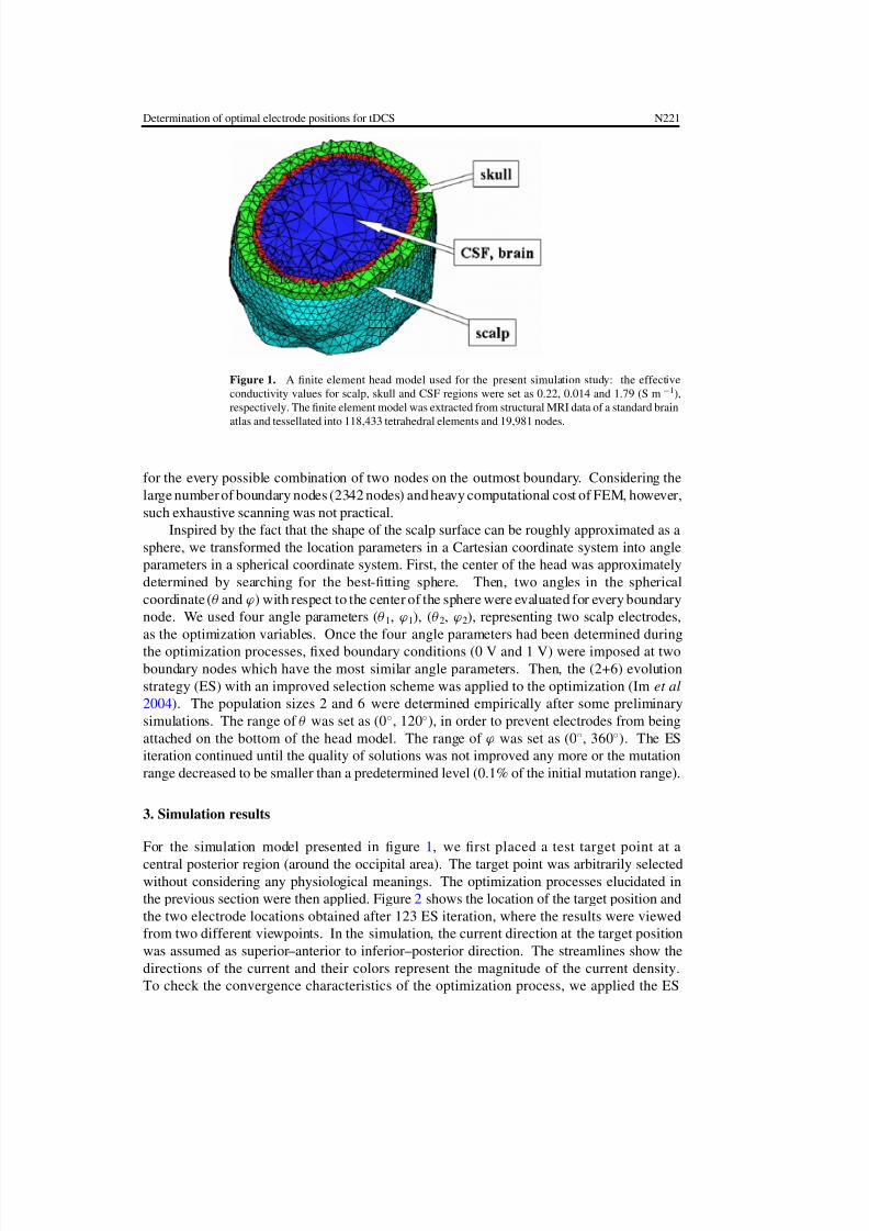
For the simulation model presented in figure 1, we first placed a test target point at a
central posterior region (around the occipital area). The target point was arbitrarily selectedwithout considering any physiological meanings. The optimization processes elucidated in
the previous section were then applied. Figure 2 shows the location of the target position and
the two electrode locations obtained after 123 ES iteration, where the results were viewed
from two different viewpoints. In the simulation, the current direction at the target position
was assumed as superior–anterior to inferior–posterior direction. The streamlines show the
directions of the current and their colors represent the magnitude of the current density.
To check the convergence characteristics of the optimization process, we applied the ES
7/21/2019 posicao eletrodos tdcs
http://slidepdf.com/reader/full/posicao-eletrodos-tdcs 4/7
N222 C-H Im et al
Figure 2. Optimized electrode locations and streamlines of current starting from multiple pointsaround electrode 1, when the target brain area is around central posterior position (A: anterior,P: posterior, R: right, L: left). The two figures were obtained from different viewpoints. Thestreamlines show the directions of the currents and their colors represent the magnitude of thecurrent density. Note that the density of streamlines does not reflect the current density distributionbecause they depend on the starting points. The current density at the target was 0.117 A m −2.
optimization repeatedly to the same problem. We confirmed from the simulations that the
results of the ten executions converged to the same parameters.
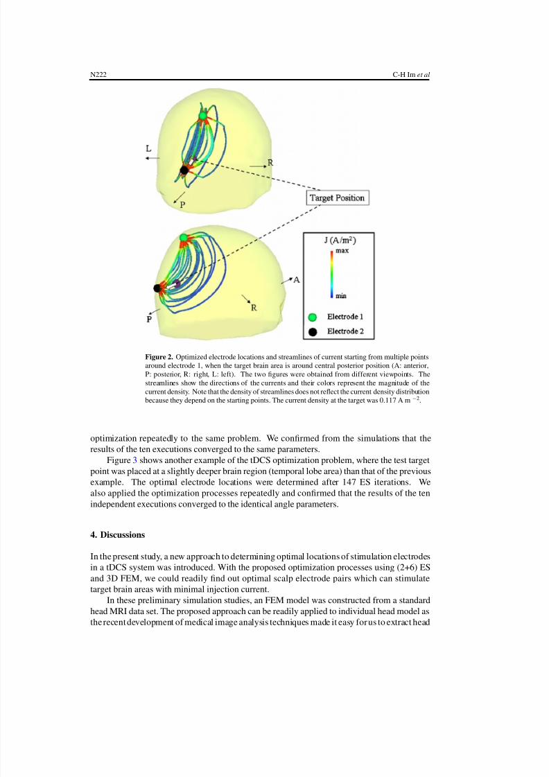
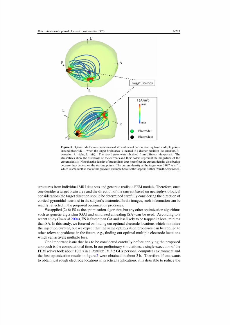
Figure 3 shows another example of the tDCS optimization problem, where the test target
point was placed at a slightly deeper brain region (temporal lobe area) than that of the previous
example. The optimal electrode locations were determined after 147 ES iterations. We
also applied the optimization processes repeatedly and confirmed that the results of the ten
independent executions converged to the identical angle parameters.
4. Discussions
In the present study, a new approach to determining optimal locations of stimulation electrodes
in a tDCS system was introduced. With the proposed optimization processes using (2+6) ES
and 3D FEM, we could readily find out optimal scalp electrode pairs which can stimulate
target brain areas with minimal injection current.
In these preliminary simulation studies, an FEM model was constructed from a standard
head MRI data set. The proposed approach can be readily applied to individual head model as
the recent development of medical image analysis techniques made it easy for us to extract head
7/21/2019 posicao eletrodos tdcs
http://slidepdf.com/reader/full/posicao-eletrodos-tdcs 5/7
Determination of optimal electrode positions for tDCS N223
Figure 3. Optimized electrode locations and streamlines of current starting from multiple pointsaround electrode 1, when the target brain area is located in a deeper position (A: anterior, P:posterior, R: right, L: left). The two figures were obtained from different viewpoints. Thestreamlines show the directions of the currents and their colors represent the magnitude of thecurrent density. Note that the density of streamlines does not reflect the current density distributionbecause they depend on the starting points. The current density at the target was 0.077 A m−2,which is smaller than that of the previous example because the target is further from the electrodes.
structures from individual MRI data sets and generate realistic FEM models. Therefore, once
one decides a target brain area and the direction of the current based on neurophysiological
consideration (the target direction should be determined carefully considering the direction of
cortical pyramidal neurons) in the subject’s anatomical brain images, such information can be
readily reflected in the proposed optimization processes.
We applied (2+6) ES as the optimization algorithm, but any other optimization algorithms
such as genetic algorithm (GA) and simulated annealing (SA) can be used. According to a
recent study (Im et al 2004), ES is faster than GA and less likely to be trapped in local minima
than SA. In this study, we focused on finding out optimal electrode locations which minimize
the injection current, but we expect that the same optimization processes can be applied toother relevant problems in the future, e.g., finding out optimal multiple electrode locations
which can activate multiple foci.
One important issue that has to be considered carefully before applying the proposed
approach is the computational time. In our preliminary simulations, a single execution of the
FEM solver took about 10.2 s in a Pentium IV 3.2 GHz personal computer environment and
the first optimization results in figure 2 were obtained in about 2 h. Therefore, if one wants
to obtain just rough electrode locations in practical applications, it is desirable to reduce the
7/21/2019 posicao eletrodos tdcs
http://slidepdf.com/reader/full/posicao-eletrodos-tdcs 6/7
N224 C-H Im et al
model order (the number of tetrahedral elements). In our future studies, we will perform
several simulations with different head models, which can be used to determine the model
orders adequate for the specific applications.
As in the other neuroelectromagnetic problems, the tDCS field analysis is hard to verify
with in vivo experiments because we can hardly measure the electrical current flow directly inthe human brain. Therefore, future studies should be focused on the experimental validation of
the tDCS field analysis. It is expected that human skull phantom experiments and simultaneous
tDCS-EEG recordings might be the alternative options.
In the present simulation study, we did not separate the CSF and brain regions, which
have slightly different conductivity values (the effective conductivity values of CSF and brain
are 1.79 and 0.22 S m−1, respectively), in order to reduce model complexity due to the folded
cortical structures. Although the brain region has been often neglected in similar current
conduction problems such as EEG forward calculations (Liu et al 2002), it can be taken into
account in our future studies to enhance the computational accuracy.
As mentioned in the introduction, TMS (including repetitive-TMS) has several advantages
over tDCS in that TMS is less invasive and its induced current distribution is more focalized
than tDCS. Nevertheless, tDCS is still useful for patients who need long-term or frequenttherapy. The patients cannot move their heads at all during the TMS therapy, while they can
freely move their heads during the tDCS therapy. The tDCS system can be used even in mobile
environments if it is installed in a wheelchair or a bed. We expect that our work will make a
contribution to the popularization of tDCS because the approach proposed in the present study
can be a potential solution for the targeting and safety issues of the tDCS system.
Acknowledgments
We thank the anonymous reviewers for constructive comments to the original version of
the manuscript. This work was supported in part by a grant of the Korea Health 21 R&D
Project, Ministry of Health and Welfare, Korea (02-PJ3-PG6-EV07-0002) and in part by a
grant (M103KV010016-06K2201-01610) from the Brain Research Center of the 21st CenturyFrontier Research Program funded by the Ministry of Science and Technology of the Republic
of Korea.
References
Fregni F, Boggio P S, Nitsche M and Pascual-Leone A 2005 Transcranial direct current stimulation Br. J.
Psychiatr y 186 446–7
Fregni F and Pascual-Leone A 2007 Technology insight: noninvasive brain stimulation in neurology-perspectives on
the therapeutic potential of rTMS and tDCS Nat. Clin. Pract. Neurol. 3 383–93
Fregni F, Thome-Souza S, Nitsche M A, Freedman S D, Valente K D and Pascual-Leone A 2006 A controlled clinical
trial of cathodal DC polarization in patients with refractory epilepsy Epilepsia 47 335–42
Haueisen J, Ramon C, Eiselt M, Brauer H and Nowak H 1997 Influence of tissue resistivities on neuromagnetic fields
and electric potentials studied with a finite element model of the head IEEE Trans. Biomed. Eng. 44 727–35
Holdefer R N, Sadleir R and Russell M J 2006 Predicted current densities in the brain during transcranial electrical
stimulation Clin. Neurophysiol. 117 1388–97
Im C H, Jung H K, Han J Y, Lee H R and Lee S Y 2004 Fast and robust localization of brain electrical sources using
evolution strategies Int. J. Appl. Electromech. 20 197–203
Im C H and Lee C 2006 Computer-aided performance evaluation of a multi-channel transcranial magnetic stimulation
system IEEE Trans. Magn. 42 3803–8
Jin J 2002 The Finite Element Method in Electromagnetics 2nd edn (New York: Wiley)
Liu A K, Dale A M and Belliveau J W 2002 Monte Carlo simulation studies of EEG and MEG localization accuracy
Hum. Brain Mapp. 16 47–62

7/21/2019 posicao eletrodos tdcs
http://slidepdf.com/reader/full/posicao-eletrodos-tdcs 7/7
Determination of optimal electrode positions for tDCS N225
Mignon A, Laudenbach V, GuischardF, Limoge A, DesmontsJ M andMantz J 1996 Transcutaneouscranial electrical
stimulation (Limoge’s currents) decreases early buprenorphine analgesic requirements after abdominal surgery
Anesth. Analg. 83 771–5
Miranda P C, Correia L, Salvador R and Basser P J 2007 Tissue heterogeneity as a mechanism for localized neural
stimulation by applied electric fields Phys. Med. Biol. 52 5603–17
Miranda P C, Lomarev M and Hallett M 2006 Modeling the current distribution during transcranial direct current
stimulation Clin. Neurophysiol. 117 1623–9
Nitsche M A and Paulus W 2000 Excitability changes induced in the human motor cortex by weak transcranial direct
current stimulation J. Physiol. (London) 527 633–9
Priori A 2003 Brain polarization in humans: a reappraisal of an old tool for prolonged non-invasive modulation of
brain excitability Clin. Neurophysiol. 114 589–95
Salinas F S, Lancaster J L and Fox P T 2007 Detailed 3D models of the induced electric field of transcranial magnetic
stimulation coils Phys. Med. Biol. 52 2879–92