Embed Size (px)
Citation preview
日本語
中文
English
Deu
tsch
Fran
çais
Españ
ol
Italiano
Русский
JA
ZH
RU
IT
ES
FR
DE
EN
Owner’s Manual
Bedienungsanleitung
Mode d’emploi
Manual de instrucciones
Manuale di istruzioni
Руководство пользователя
取扱説明書
POWER AMPLIFIER
2
XMV4280/XMV4140/XMV4280-D/XMV4140-D Owner’s ManualThe above warning is located on the top of the unit.
Explanation of Graphical Symbols
The lightning flash with arrowhead symbol within an equilateral triangle is intended to alert the user to the presence of uninsulated “dangerous voltage” within the product’s enclosure that may be of sufficient magnitude to constitute a risk of electric shock to per-sons.
The exclamation point within an equilateral triangle is intended to alert the user to the presence of important operating and mainte-nance (servicing) instructions in the literature accompanying the product.
IMPORTANT SAFETY INSTRUCTIONS
1 Read these instructions.
2 Keep these instructions.
3 Heed all warnings.
4 Follow all instructions.
5 Do not use this apparatus near water.
6 Clean only with dry cloth.
7 Do not block any ventilation openings. Install in
accordance with the manufacturer’s instructions.
8 Do not install near any heat sources such as radia-
tors, heat registers, stoves, or other apparatus
(including amplifiers) that produce heat.
9 Do not defeat the safety purpose of the polarized or
grounding-type plug. A polarized plug has two blades
with one wider than the other. A grounding type plug
has two blades and a third grounding prong. The
wide blade or the third prong are provided for your
safety. If the provided plug does not fit into your out-
let, consult an electrician for replacement of the
obsolete outlet.
10 Protect the power cord from being walked on or
pinched particularly at plugs, convenience recepta-
cles, and the point where they exit from the appara-
tus.
11 Only use attachments/accessories specified by the
manufacturer.
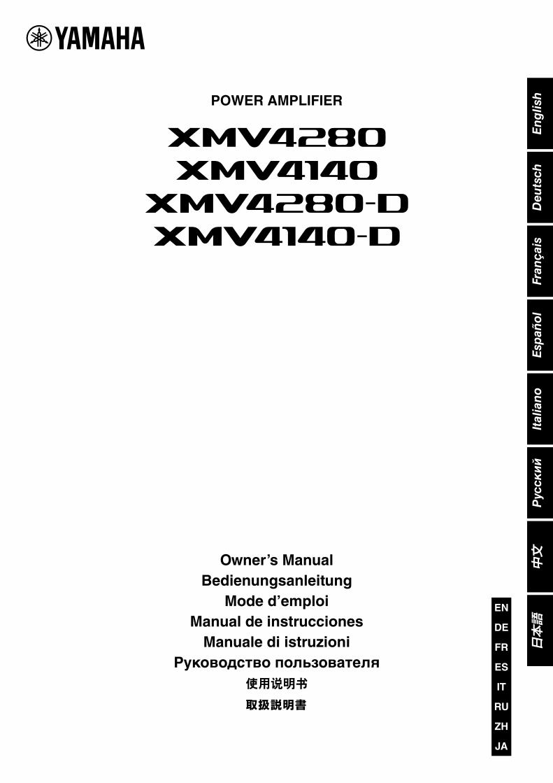
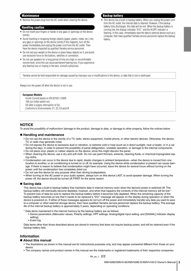
12 Use only with the cart, stand,
tripod, bracket, or table speci-
fied by the manufacturer, or
sold with the apparatus. When
a cart is used, use caution
when moving the cart/appara-
tus combination to avoid injury
from tip-over.
13 Unplug this apparatus during lightning storms or
when unused for long periods of time.
14 Refer all servicing to qualified service personnel. Ser-
vicing is required when the apparatus has been dam-
aged in any way, such as power-supply cord or plug
is damaged, liquid has been spilled or objects have
fallen into the apparatus, the apparatus has been
exposed to rain or moisture, does not operate nor-
mally, or has been dropped.
(UL60065_03)
CAUTION: TO REDUCE THE RISK OF
ELECTRIC SHOCK, DO NOT REMOVE
COVER (OR BACK). NO USER-SERVICEABLE
PARTS INSIDE. REFER SERVICING TO
QUALIFIED SERVICE PERSONNEL.
CAUTION
RISK OF ELECTRIC SHOCKDO NOT OPEN
WARNING
TO REDUCE THE RISK OF FIRE OR ELECTRIC SHOCK, DO NOT EXPOSE THIS APPARATUS TO RAIN OR MOISTURE.
ADVARSEL!
Lithiumbatteri—Eksplosionsfare ved fejlagtig håndtering. Udskiftning må kun ske med batteri af samme fabrikat og type. Levér det brugte batteri tilbage til leverandoren.
VARNING
Explosionsfara vid felaktigt batteribyte. Använd samma batterityp eller en ekvivalent typ som rekommenderas av apparattillverkaren. Kassera använt batteri enligt fabrikantens instruktion.
VAROITUS
Paristo voi räjähtää, jos se on virheellisesti asennettu. Vaihda paristo ainoastaan laitevalmistajan suosittelemaan tyyppiin. Hävitä käytetty paristo valmistajan ohjeiden mukaisesti.
(lithium caution)
XMV4280/XMV4140/XMV4280-D/XMV4140-D Owner’s Manual 3
1. IMPORTANT NOTICE: DO NOT MODIFY THIS UNIT!This product, when installed as indicated in the instructions contained in this manual, meets FCC requirements. Modifi-cations not expressly approved by Yamaha may void your authority, granted by the FCC, to use the product.
2. IMPORTANT: When connecting this product to accessories and/or another product use only high quality shielded cables. Cable/s supplied with this product MUST be used. Follow all installation instructions. Failure to follow instructions could void your FCC authorization to use this product in the USA.
3. NOTE: This product has been tested and found to comply with the requirements listed in FCC Regulations, Part 15 for Class “B” digital devices. Compliance with these require-ments provides a reasonable level of assurance that your use of this product in a residential environment will not result in harmful interference with other electronic devices. This equipment generates/uses radio frequencies and, if not installed and used according to the instructions found in the users manual, may cause interference harmful to the opera-tion of other electronic devices. Compliance with FCC regu-lations does not guarantee that interference will not occur in
all installations. If this product is found to be the source of interference, which can be determined by turning the unit “OFF” and “ON”, please try to eliminate the problem by using one of the following measures:Relocate either this product or the device that is being affected by the interference.Utilize power outlets that are on different branch (circuit breaker or fuse) circuits or install AC line filter/s.In the case of radio or TV interference, relocate/reorient the antenna. If the antenna lead-in is 300 ohm ribbon lead, change the lead-in to co-axial type cable.If these corrective measures do not produce satisfactory results, please contact the local retailer authorized to distrib-ute this type of product. If you can not locate the appropriate retailer, please contact Yamaha Corporation of America, Electronic Service Division, 6600 Orangethorpe Ave, Buena Park, CA90620The above statements apply ONLY to those products distrib-uted by Yamaha Corporation of America or its subsidiaries.
* This applies only to products distributed by YAMAHA CORPORATION OF AMERICA. (class B)
FCC INFORMATION (U.S.A.)
COMPLIANCE INFORMATION STATEMENT
(DECLARATION OF CONFORMITY PROCEDURE)
Responsible Party : Yamaha Corporation of AmericaAddress : 6600 Orangethorpe Ave., Buena Park,
Calif. 90620Telephone : 714-522-9011
Type of Equipment : Power AmplifierModel Name : XMV4280/XMV4140/XMV4280-D/
XMV4140-D
This device complies with Part 15 of the FCC Rules.Operation is subject to the following two conditions:1) this device may not cause harmful interference, and2) this device must accept any interference received including
interference that may cause undesired operation.See user manual instructions if interference to radio reception
* This applies only to products distributed by YAMAHA CORPORATION OF AMERICA.
(FCC DoC)
IMPORTANT NOTICE FOR THE UNITED KINGDOM
Connecting the Plug and CordWARNING: THIS APPARATUS MUST BE EARTHED IMPOR-TANT. The wires in this mains lead are coloured in accordance with the following code:
GREEN-AND-YELLOW : EARTHBLUE : NEUTRALBROWN : LIVE
As the colours of the wires in the mains lead of this apparatus may not correspond with the coloured markings identifying the terminals in your plug proceed as follows:
The wire which is coloured GREEN-and-YELLOW must be connected to the terminal in the plug which is marked by the letter E or by the safety earth symbol or colored GREEN or GREEN-and-YELLOW.
The wire which is coloured BLUE must be connected to the terminal which is marked with the letter N or coloured BLACK.
The wire which is coloured BROWN must be connected to the terminal which is marked with the letter L or coloured RED.
(3 wires)
In Finland: Laite on liitettävä suojamaadoituskoskettimilla varustettuun pistorasiaan.In Norway: Apparatet må tilkoples jordet stikkontakt.In Sweden: Apparaten skall anslutas till jordat uttag.
(class I hokuo)
This product contains a battery that contains perchlorate material.Perchlorate Material—special handling may apply,See www.dtsc.ca.gov/hazardouswaste/perchlorate.
* This applies only to products distributed by YAMAHA CORPORATION OF AMERICA. (Perchlorate)
이 기기는 가정용(B급) 전자파적합기기로서 주로 가정에서 사용하는 것을 목적으로 하며, 모든 지역에서 사용할 수 있습니다.
(class b korea)
4
PRECAUTIONSPLEASE READ CAREFULLY BEFORE PROCEEDING
* Please keep this manual in a safe place for future reference.
WARNINGAlways follow the basic precautions listed below to avoid the possibility of serious injury or even death from electrical shock, short-circuiting, damages, fire or other hazards. These precautions include, but are not limited to, the following:
• Do not place the power cord near heat sources such as heaters or radiators, and do not excessively bend or otherwise damage the cord, place heavy objects on it, or place it in a position where anyone could walk on, trip over, or roll anything over it.
• Only use the voltage specified as correct for the device. The required voltage is printed on the name plate of the device.
• Use only the supplied power cord/plug.If you intend to use the device in an area other than in the one you purchased, the included power cord may not be compatible. Please check with your Yamaha dealer.
• Check the electric plug periodically and remove any dirt or dust which may have accumulated on it.
• Be sure to connect to an appropriate outlet with a protective grounding connection. Improper grounding can result in electrical shock, damage to the device(s), or even fire.
• This device contains no user-serviceable parts. Do not open the device or attempt to disassemble the internal parts or modify them in any way. If it should appear to be malfunctioning, discontinue use immediately and have it inspected by qualified Yamaha service personnel.
• Do not expose the device to rain, use it near water or in damp or wet conditions, or place on it any containers (such as vases, bottles or glasses) containing liquids which might spill into any openings. If any liquid such as water seeps into the device, turn off the power immediately and unplug the power cord from the AC outlet. Then have the device inspected by qualified Yamaha service personnel.
• Never insert or remove an electric plug with wet hands.
• Do not put burning items, such as candles, on the unit. A burning item may fall over and cause a fire.
• When one of the following problems occur, immediately turn off the power switch and disconnect the electric plug from the outlet. Then have the device inspected by Yamaha service personnel.- The power cord or plug becomes frayed or damaged.- It emits unusual smells or smoke.- Some object has been dropped into the device.- There is a sudden loss of sound during use of the device.
• If this device should be dropped or damaged, immediately turn off the power switch, disconnect the electric plug from the outlet, and have the device inspected by qualified Yamaha service personnel.
CAUTIONAlways follow the basic precautions listed below to avoid the possibility of physical injury to you or others, or damage to the device or other property. These precautions include, but are not limited to, the following:
• When removing the electric plug from the device or an outlet, always hold the plug itself and not the cord. Pulling by the cord can damage it.
• Remove the electric plug from the outlet when the device is not to be used for extended periods of time, or during electrical storms.
• Do not place the device in an unstable position where it might accidentally fall over.
• Do not block the vents. This device has ventilation holes at the front/rear/sides to prevent the internal temperature from becoming too high. In particular, do not place the device on its side or upside down. Inadequate ventilation can result in overheating, possibly causing damage to the device(s), or even fire.
• Do not use the device in a confined, poorly-ventilated location. If this device is to be used in a small space other than an EIA-standard rack, make sure that there is adequate space between the device and surrounding walls or other devices: at least 10 cm at the sides, 10 cm behind and 40 cm above. Inadequate ventilation can result in overheating, possibly causing damage to the device(s), or even fire.
• Do not place the device in a location where it may come into contact with corrosive gases or salt air. Doing so may result in malfunction.
• Keep device away from the reach of children.• Before moving the device, remove all connected cables.• When setting up the device, make sure that the AC outlet you are using is
easily accessible. If some trouble or malfunction occurs, immediately turn off the power switch and disconnect the plug from the outlet. Even when the power switch is turned off, electricity is still flowing to the product at the minimum level. When you are not using the product for a long time, make sure to unplug the power cord from the wall AC outlet.
• If the device is mounted in an EIA standard rack, carefully read the section “Precautions for Rack Mounting” on page 8. Inadequate ventilation can result in overheating, possibly causing damage to the device(s), malfunction, or even fire.
• Before connecting the device to other devices, turn off the power for all devices. Before turning the power on or off for all devices, set all volume levels to minimum.
• Use only speaker cables for connecting speakers to the speaker connectors. Use of other types of cables may result in fire.
Power supply/power cord
Do not open
Water warning
Fire warning
If you notice any abnormality
Power supply/power cord
Location
Connections
PA_en_1 1/2
XMV4280/XMV4140/XMV4280-D/XMV4140-D Owner’s Manual
XMV4280/XMV4140/XMV4280-D/XMV4140-D Owner’s Manual 5
• Remove the power plug from the AC outlet when cleaning the device.
• Do not insert your fingers or hands in any gaps or openings on the device (vents).
• Avoid inserting or dropping foreign objects (paper, plastic, metal, etc.) into any gaps or openings on the device (vents) If this happens, turn off the power immediately and unplug the power cord from the AC outlet. Then have the device inspected by qualified Yamaha service personnel.
• Do not rest your weight on the device or place heavy objects on it, and avoid use excessive force on the buttons, switches or connectors.
• Do not use speakers for a long period of time at a high or uncomfortable volume level, since this can cause permanent hearing loss. If you experience any hearing loss or ringing in the ears, consult a physician.
• This device has a built-in backup battery. When you unplug the power cord from the AC outlet, the internal data is retained. However, if the backup battery fully discharges, this data will be lost. When the backup battery is running low, the display indicates “012.” and the ALERT indicator is flashing. In this case, immediately save the data to external device such as a computer, then have qualified Yamaha service personnel replace the backup battery.
Always turn the power off when the device is not in use.
NOTICETo avoid the possibility of malfunction/ damage to the product, damage to data, or damage to other property, follow the notices below.
Handling and maintenance
• Do not use the device in the vicinity of a TV, radio, stereo equipment, mobile phone, or other electric devices. Otherwise, the device, TV, or radio may generate noise.
• Do not expose the device to excessive dust or vibration, or extreme cold or heat (such as in direct sunlight, near a heater, or in a car during the day), in order to prevent the possibility of panel disfiguration, unstable operation, or damage to the internal components.
• Do not place vinyl, plastic or rubber objects on the device, since this might discolor the panel.• When cleaning the device, use a dry and soft cloth. Do not use paint thinners, solvents, cleaning fluids, or chemical-impregnated wip-
ing cloths.• Condensation can occur in the device due to rapid, drastic changes in ambient temperature—when the device is moved from one
location to another, or air conditioning is turned on or off, for example. Using the device while condensation is present can cause dam-age. If there is reason to believe that condensation might have occurred, leave the device for several hours without turning on the power until the condensation has completely dried out.
• Do not use this device for any purpose other than driving loudspeakers.• When turning on the AC power in your audio system, always turn on tthe device LAST, to avoid speaker damage. When turning the
power off, the device should be turned off FIRST for the same reason.
Saving data
This device has a built-in backup battery that maintains data in internal memory even when the device’s power is switched off. The backup battery will eventually become depleted, however, and when that happens the contents of the internal memory will be lost.* To prevent loss of data be sure to replace the backup battery before it becomes fully depleted. When the remaining capacity of the backup battery becomes so low that it needs to be replaced a “012.” message will appear on the display during operation or when the device is powered on. If either of these messages appears do not turn off the power and immediately transfer any data you want to save to a computer or other external storage device, then have qualified Yamaha service personnel replace the backup battery. The average life of the internal backup battery is approximately 5 years, depending on operating conditions.
* Data items maintained in the internal memory by the backup battery are as follows:• Device parameters (Attenuator values, Polarity settings, HPF settings, Analog/digital input setting, and [SIGNAL] indicator display
setting).• Event log.
Data items other than those described above are stored in memory that does not require backup power, and will be retained even if the backup battery fails.
Information
About this manual
• The illustrations as shown in this manual are for instructional purposes only, and may appear somewhat different from those on your device.
• The company names and product names in this manual are the trademarks or registered trademarks of their respective companies.
Maintenance
Handling caution
Backup battery
Yamaha cannot be held responsible for damage caused by improper use or modifications to the device, or data that is lost or destroyed.
European ModelsInrush Current based on EN 55103-1:200910A (on initial switch-on)5A (after a supply interruption of 5s)Conforms to Environments: E1, E2, E3 and E4
PA_en_1 2/2
XMV4280/XMV4140/XMV4280-D/XMV4140-D Owner’s Manual6
Contents
Introduction.....................................................................................................................7
Features.................................................................................................................................. 7
Included items......................................................................................................................... 7
Related Manuals and Software ............................................................................................... 7
Firmware Updates................................................................................................................... 8
About Dante ............................................................................................................................ 8
Precautions for Rack Mounting ............................................................................................... 8
Controls and Functions .................................................................................................9
Front Panel.............................................................................................................................. 9
Rear Panel ............................................................................................................................ 12
Connections and Setting Up .......................................................................................16
Setup for Analog Signal Input ............................................................................................... 16
[REMOTE] and [FAULT OUTPUT] Connectors ..................................................................... 21
Operations.....................................................................................................................23
Front Panel Operations ......................................................................................................... 23
Initializing the Internal Memory............................................................................................. 25
Appendix .......................................................................................................................26
Troubleshooting..................................................................................................................... 26
Alert Numbers and Content .................................................................................................. 27
Dante Messages (XMV4280-D/XMV4140-D only) ................................................................ 29
High-impedance and Low-impedance Connections ............................................................. 30
BTL (Balanced Transformer Less) Connection ..................................................................... 31
Specifications .............................................................................................................234
General Specifications ........................................................................................................ 234
Block Diagram..................................................................................................................... 236
Dimensions ......................................................................................................................... 236
Current Draw and Heat Dissipation .................................................................................... 237
* The contents of this manual apply to the latest specifications as of the printing date. Since Yamaha makes continuous improvements to the product, this manual may not apply to the specifications of your particular product. To obtain the lat-est manual, access the Yamaha website then download the manual file. Since specifications, equipment or separately sold accessories may not be the same in every locale, please check with your Yamaha dealer.
XMV4280/XMV4140/XMV4280-D/XMV4140-D Owner’s Manual 7
IntroductionThank you for your purchase of the Yamaha XMV4280, XMV4140, XMV4280-D or XMV4140-D power
amplifier. Please read through this manual carefully before beginning use, so that you will be able to take full
advantage of your power amplifier’s superlative features and enjoy trouble-free operation for years to come.
After you have read the manual, keep it in a safe place for reference when needed.
The XMV is a multi-channel power amplifier with the follow-ing features.
• Both high-impedance and low-impedance connec-
tions are supported
Both high-impedance connections to 70V/100V lines and 4Ω/8Ω low-impedance connections are supported. A rear panel DIP switch allows this setting to be specified for every two channels.
• Newly-developed “Double Power mode”
The newly-developed “Double Power mode” doubles the amplifier output of each channel when low-impedance con-nections are used.
* The number of available channels will be halved.
• Settings can be made via application software
Although settings such as mute on/off and attenuator values can be edited from the panel of the amplifier itself, you can use an MTX series matrix processor and computer to edit the settings of multiple XMV units.
• Support for the newly-developed “YDIF” digital
audio transmission format
(XMV4280/XMV4140 only)
This allows up to 16 channels of audio and word clock to be transmitted and received via an Ethernet cable.This model can receive four channels of audio signals via YDIF.
• Dante network for large-scale systems
(XMV4280-D/XMV4140-D only)
This enables audio signal transfer over long-distance with Dante equipped devices (such as the MTX5-D) with stan-dard Ethernet cables.
• High efficiency
The newly-developed output circuits allows high efficiency.
• Redundancy between the digital and analog inputs
When the pilot tone of a digital input is interrupted or an analog input reaches the specified level or higher, the input switches from digital to analog.
* This function can be set from the Amp Editor.
• Owner’s Manual• Power cord• Euroblock plugs (3-pin, 3.50mm pitch) x 2• Euroblock plugs with tabs (3-pin, 5.08mm pitch) x 4• Cable ties x 4
Use the MTX-MRX Editor for building a system in which the MTX/MRX and XMV are combined. Use the Amp Editor for a system consisting only of the XMV(s). Related manuals, of the MTX-MRX Editor or Amp Editor (heretofore collectively referred to as “the editor”) can be downloaded from the down-load page of the following website.
http://www.yamahaproaudio.com/
• List of related manuals
The “MTX-MRX Editor User Guide,” “MTX Setup Manual,” “MRX Setup Manual,” and “Amp Editor Owner’s Manual” are electronic files in PDF format.You can read the books on a computer. Use Adobe® Reader® to read the books on screen, search for words very quickly, print specific pages, or click links to display sections of special inter-est. The ability to search for words, or to follow links directly to relevant sections in the document, are helpful attributes of this electronic file format. We encourage you to take advantage of these benefits.You can download the latest Adobe Reader application from the website listed below.
http://www.adobe.com/
NOTE• When there are differences in the specifications of the XMV4280/XMV4280-D and the XMV4140/XMV4140-D, this manual will
use curly brackets { } to enclose information that applies only to the XMV4140/XMV4140-D.(Example: 280W {140W}).
• Unless otherwise specified, illustrations are taken from the XMV4280/XMV4280-D.
• For the remainder of this manual, the XMV4280, XMV4140, XMV4280-D and XMV4140-D are referred to as “XMV” collectively.
• In this book, the matrix processor MTX series units are reffered to as “MTX” collectively.
Features Included items (please check)
Related Manuals and Software
MTX or MRX
owner’s manual
This explains how to use the proces-sor (MTX or MRX).
MTX-MRX Editor
User Guide
This explains how to use MTX-MRX Editor.
MTX Setup Manual
MRX Setup Manual
This explains how to use and set up the matrix processor MTX and MRX series that is used along with the XMV power amp.
Amp Editor
Owner’s ManualThis explains how to use Amp Editor.

Introduction
8
XMV4280/XMV4140/XMV4280-D/XMV4140-D Owner’s ManualUse the MTX-MRX Editor or the Amp Editor to update the firmware of the XMV or check the firmware version. For opera-tion details, refer to the related manuals.You can download the latest firmware from the “Downloads” page on the following website.
http://www.yamahaproaudio.com/
The XMV4280-D/XMV4140-D units feature Dante technology as a protocol to transmit audio signals. Dante is a network pro-tocol developed by Audinate. It is designed to deliver multi-channel audio signals at various sampling and bit rates, as well as device control signals over a Giga-bit Ethernet (GbE) net-work. Dante also offers the following benefits:
• It transmits up to 512 in/512 out, for a total 1024 channels (theoretically) of audio over a GbE network. (The XMV4280-D/XMV4140-D features four inputs with a 24/32-bit resolution.)
• Dante-enabled devices will automatically configure their network interfaces and find each other on the network. You can label Dante devices and their audio channels with names that make sense to you.
• Dante uses high accuracy network synchronization standards to achieve sample-accurate playback with extremely low latency and jitter. (Four types of latency are available on the XMV4280-D/XMV4140-D: 0.25 msec, 0.5 msec, 1.0 msec, and 5.0 msec.)
• Dante supports redundant connections via primary and sec-ondary circuits to defend against unforeseen difficulties.
• Connecting a Dante-enabled device to a computer over Ethernet enables you to directly input or output audio signals without using any audio interface devices.
Visit Audinate website for more details on Dante.http://www.audinate.com/
More information on Dante is also posted on the Yamaha Pro Audio website:
http://www.yamahaproaudio.com/
Firmware Updates
About Dante
NOTEPlease do not use the EEE function (*) of network switches in a Dante network.
Although power management should be negotiated automati-cally in switches that support EEE, some switches do not per-form the negotiation properly. This may cause EEE to be enabled in Dante networks when it is not appropriate, resulting in poor synchronization perfor-mance and occasional dropouts.
Therefore we strongly recommend that:
- If you use managed switches, ensure that they allow EEE to be disabled. Make sure that EEE is disabled on all ports used for real-time Dante traffic.
- If you use unmanaged switches, make sure to not use net-work switches that support the EEE function, since EEE operation cannot be disabled in these switches.
* EEE (Energy Efficient Ethernet) is a technology that reduces switch power consumption during periods of low network traffic. It is also known as Green Ethernet and IEEE802.3az.
Precautions for Rack Mounting
This unit is rated for operation at ambient temperatures ranging from 0 to 40 degrees Celsius. When mounting the unit with other XMV unit(s) or other device(s) in an EIA standard equipment rack, internal temperatures can exceed the specified upper limit, resulting in impaired performance or failure. When rack mounting the unit, always observe the following requirements to avoid heat buildup:
• When mounting the unit in a rack with devices such as power amplifiers that generate a significant amount of heat, leave more than 1U of space between the XMV and other equipment. Also either leave the open spaces uncovered or install appropriate ventilating pan-els to minimize the possibility of heat buildup.
• To ensure sufficient airflow, leave the rear of the rack open and position it at least 10 centimeters from walls or other surfaces. If the rear of the rack can’t be left open, install a commercially available fan or similar ventilating option to secure sufficient airflow. If you’ve installed a fan kit, there may be cases in which closing the rear of the rack will produce a greater cooling effect. Refer to the rack and/or fan unit manual for details.

Controls and Functions
XMV4280/XMV4140/XMV4280-D/XMV4140-D Owner’s Manual 9
XMV4280/XMV4140
XMV4280-D/XMV4140-D
q Power switch
Turns power to the unit ON or OFF. Setting the switch to the upward position turns the power on; the [POWER] indicator !0 will light green. Setting the switch to the downward posi-tion turns the power off. If the switch is in the upward posi-tion and the [POWER] indicator is flashing, the unit is in standby mode.
w [PROTECTION] A/B/C/D indicators
When the protection system is active, the indicator will light orange. If the audio output is muted, turn off the power and wait for the XMV to cool before turning the power on again. The protection circuit will operate and the [PROTECTION] indicator will light in the following situations.
If the amplifier overheats and the output lim-
iter operates
The speaker output will be attenuated if the heat sink of the amplifier section exceeds 80°C, and will be muted if the heat sink exceeds 90°C. The [PROTECTION] indica-tor will light at 80°C or higher.
If the power supply overheats and shuts-down
The fan will rotate at high speed if the power supply sec-tion exceeds 90°C, and the analog circuits will shut down if it exceeds 100°C.The [PROTECTION] indicator will light at 100°C or higher.
Front Panel
q wer!8 !8 !0
i t u !7o
!1 !2!3
!6
y
q wer!8 !8 !0
i t u !7o
!1
!6
y !4!5
CAUTION• To ensure that high-volume noise is not output from
the speakers, power-on the equipment starting with
the audio sources, then the mixer and processors
(such as the MTX), and finally the amplifiers. Reverse
this order when turning the system off.
• Rapidly turning the power switch ON and OFF in suc-
cession can cause the unit to malfunction. After turn-
ing the power switch OFF, wait for about 5 seconds
before turning it ON again.
• If you modified parameter settings, do not turn the
power switch OFF for at least one second. Otherwise,
the changes to the settings may be lost.
• Even when the power switch is turned off, a small
amount of current is flowing through the unit. If you
plan not to use the unit for a long period of time,
remove the power cable from the AC outlet.
Controls and Functions
10
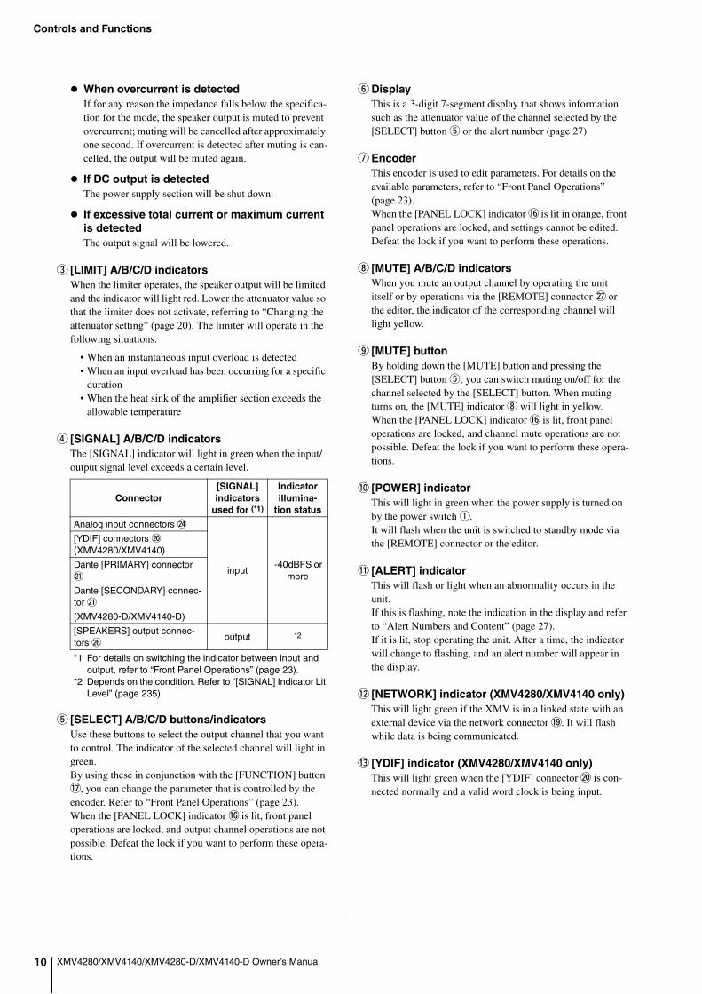
XMV4280/XMV4140/XMV4280-D/XMV4140-D Owner’s ManualWhen overcurrent is detected
If for any reason the impedance falls below the specifica-tion for the mode, the speaker output is muted to prevent overcurrent; muting will be cancelled after approximately one second. If overcurrent is detected after muting is can-celled, the output will be muted again.
If DC output is detected
The power supply section will be shut down.
If excessive total current or maximum current
is detected
The output signal will be lowered.
e [LIMIT] A/B/C/D indicators
When the limiter operates, the speaker output will be limited and the indicator will light red. Lower the attenuator value so that the limiter does not activate, referring to “Changing the attenuator setting” (page 20). The limiter will operate in the following situations.
• When an instantaneous input overload is detected• When an input overload has been occurring for a specific
duration• When the heat sink of the amplifier section exceeds the
allowable temperature
r [SIGNAL] A/B/C/D indicators
The [SIGNAL] indicator will light in green when the input/output signal level exceeds a certain level.
*1 For details on switching the indicator between input and output, refer to “Front Panel Operations” (page 23).
*2 Depends on the condition. Refer to “[SIGNAL] Indicator Lit Level” (page 235).
t [SELECT] A/B/C/D buttons/indicators
Use these buttons to select the output channel that you want to control. The indicator of the selected channel will light in green.By using these in conjunction with the [FUNCTION] button !7, you can change the parameter that is controlled by the encoder. Refer to “Front Panel Operations” (page 23).When the [PANEL LOCK] indicator !6 is lit, front panel operations are locked, and output channel operations are not possible. Defeat the lock if you want to perform these opera-tions.
y Display
This is a 3-digit 7-segment display that shows information such as the attenuator value of the channel selected by the [SELECT] button t or the alert number (page 27).
u Encoder
This encoder is used to edit parameters. For details on the available parameters, refer to “Front Panel Operations” (page 23).When the [PANEL LOCK] indicator !6 is lit in orange, front panel operations are locked, and settings cannot be edited. Defeat the lock if you want to perform these operations.
i [MUTE] A/B/C/D indicators
When you mute an output channel by operating the unit itself or by operations via the [REMOTE] connector @7 or the editor, the indicator of the corresponding channel will light yellow.
o [MUTE] button
By holding down the [MUTE] button and pressing the [SELECT] button t, you can switch muting on/off for the channel selected by the [SELECT] button. When muting turns on, the [MUTE] indicator i will light in yellow.When the [PANEL LOCK] indicator !6 is lit, front panel operations are locked, and channel mute operations are not possible. Defeat the lock if you want to perform these opera-tions.
!0 [POWER] indicator
This will light in green when the power supply is turned on by the power switch q.It will flash when the unit is switched to standby mode via the [REMOTE] connector or the editor.
!1 [ALERT] indicator
This will flash or light when an abnormality occurs in the unit.If this is flashing, note the indication in the display and refer to “Alert Numbers and Content” (page 27).If it is lit, stop operating the unit. After a time, the indicator will change to flashing, and an alert number will appear in the display.
!2 [NETWORK] indicator (XMV4280/XMV4140 only)
This will light green if the XMV is in a linked state with an external device via the network connector !9. It will flash while data is being communicated.
!3 [YDIF] indicator (XMV4280/XMV4140 only)
This will light green when the [YDIF] connector @0 is con-nected normally and a valid word clock is being input.
Connector
[SIGNAL]
indicators
used for (*1)
Indicator
illumina-
tion status
Analog input connectors @4
input -40dBFS or
more
[YDIF] connectors @0 (XMV4280/XMV4140)
Dante [PRIMARY] connector @1
Dante [SECONDARY] connec-tor @1
(XMV4280-D/XMV4140-D)
[SPEAKERS] output connec-tors @6
output *2

Controls and Functions
1
XMV4280/XMV4140/XMV4280-D/XMV4140-D Owner’s Manual 1!4 [PRIMARY]/[SECONDARY] indicators
(XMV4280-D/XMV4140-D only)
These show the communication status of the Dante [PRI-MARY]/[SECONDARY] connectors @1. They flash rapidly in green if the Ethernet cables are connected properly.
!5 [SYNC] Indicators
(XMV4280-D/XMV4140-D only)
These show the operating status of the Dante network. If the green (upper) indicator lights, the unit is operating as a word clock slave and synchronizing to the word clock. If the green indicator flashes, the unit is operating as the word clock mas-ter. If the power to the unit is turned on but the green indica-tor is turned off, the unit is not functioning properly. In this case, refer to the “Warning Messages” section (see page 29). If the orange indicator lights or flashes, refer to the “Warning Messages” section.
!6 [PANEL LOCK] indicator
This lights or flashes according to the state of the front panel lock. To specify the front panel lock setting, use the Device setup DIP switch @3.
!7 [FUNCTION] button
Use this to check or change the operating mode of the XMV’s front panel. For details on how to perform front panel operations, refer to “Front Panel Operations” (page 23).
!8 Cooling vent
Located behind the vent is a variable speed cooling fan that draws air in from the front and exhausts it through the rear. The fan speed will automatically vary according to the tem-perature.Please be sure that you do not block the air intakes or exhaust vents. You should also clean the air intakes and exhaust vents regularly. If the air intakes are clogged with dust or debris, the unit will overheat, which may result in the unit shutting down.
Indicator Status
Lit
Front panel operations are locked. Lock will be temporarily defeated if you press the [FUNCTION] button !7 and the [SELECT] A button t.
Unlit Front panel operations are not locked.
FlashingLock is temporarily defeated. When the XMV is restarted, it will be in a locked state.
Controls and Functions
12
XMV4280/XMV4140/XMV4280-D/XMV4140-D Owner’s ManualXMV4280/XMV4140
XMV4280-D/XMV4140-D
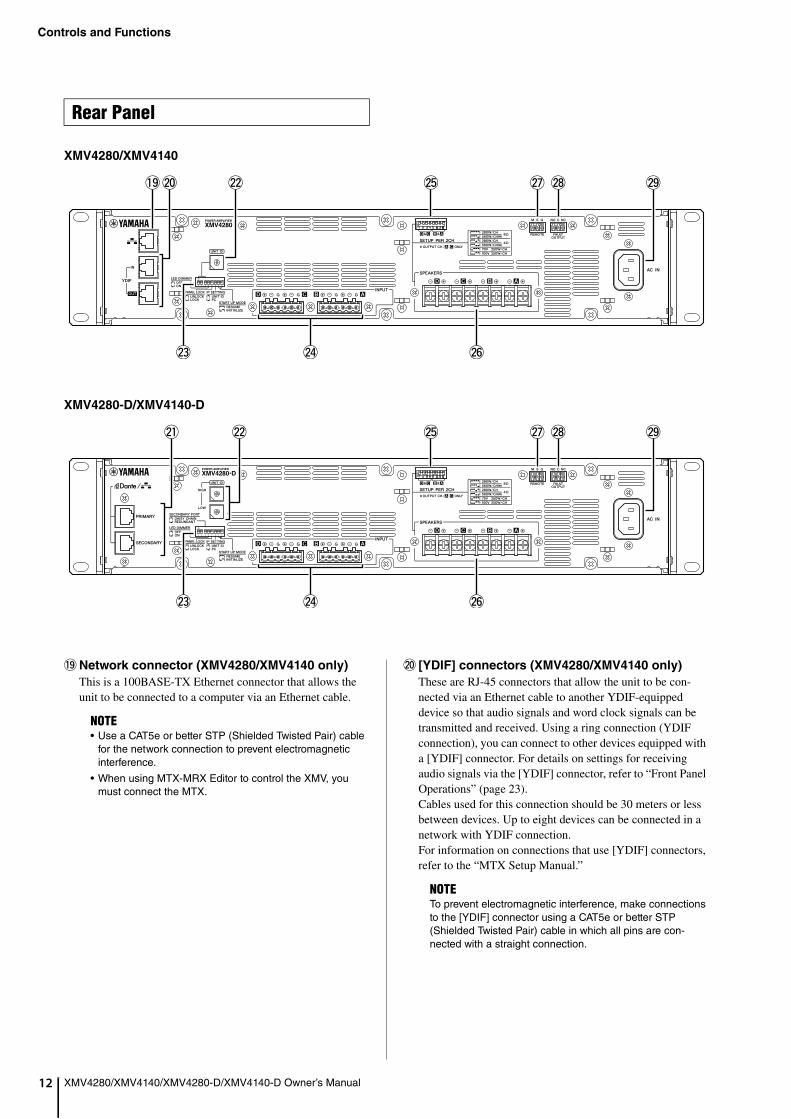
!9 Network connector (XMV4280/XMV4140 only)
This is a 100BASE-TX Ethernet connector that allows the unit to be connected to a computer via an Ethernet cable.
@0 [YDIF] connectors (XMV4280/XMV4140 only)
These are RJ-45 connectors that allow the unit to be con-nected via an Ethernet cable to another YDIF-equipped device so that audio signals and word clock signals can be transmitted and received. Using a ring connection (YDIF connection), you can connect to other devices equipped with a [YDIF] connector. For details on settings for receiving audio signals via the [YDIF] connector, refer to “Front Panel Operations” (page 23).Cables used for this connection should be 30 meters or less between devices. Up to eight devices can be connected in a network with YDIF connection.For information on connections that use [YDIF] connectors, refer to the “MTX Setup Manual.”
Rear Panel
1 2 3 4 5 6 7 8
ON
ON
@8@7@5!9 @9
@4 @6
@0 @2
@3
ON
1 2 3 4 5 6 7 8
ON
@8@7@5 @9
@4 @6
@1
@3
@2
NOTE• Use a CAT5e or better STP (Shielded Twisted Pair) cable
for the network connection to prevent electromagnetic interference.
• When using MTX-MRX Editor to control the XMV, you must connect the MTX.
NOTETo prevent electromagnetic interference, make connections to the [YDIF] connector using a CAT5e or better STP (Shielded Twisted Pair) cable in which all pins are con-nected with a straight connection.
Controls and Functions
3
XMV4280/XMV4140/XMV4280-D/XMV4140-D Owner’s Manual 1@1 Dante [PRIMARY]/[SECONDARY] connectors
(XMV4280-D/XMV4140-D only)
These are RJ-45 connectors that allow the unit to be con-nected to another Dante device such as the MTX5-D via an Ethernet cable. The Dante [PRIMARY] connector can also be used to connect to a computer via an Ethernet cable. To connect, refer to the “MTX-MRX Editor User Guide.”
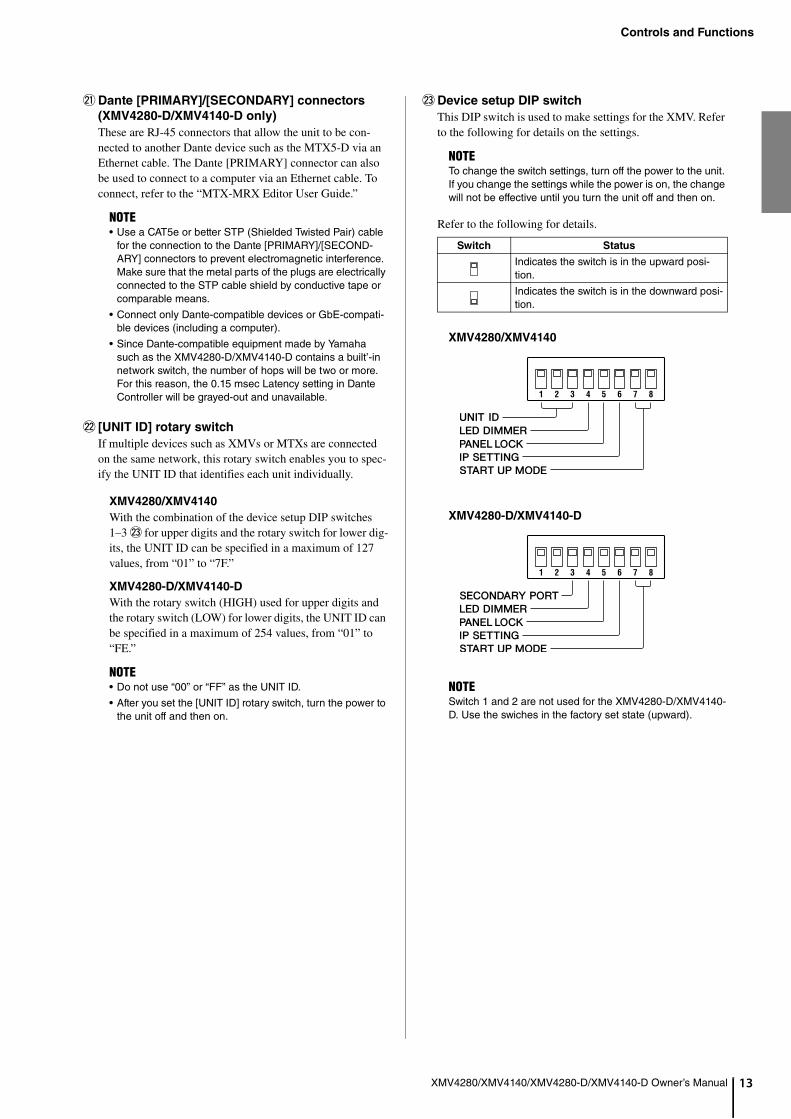
@2 [UNIT ID] rotary switch
If multiple devices such as XMVs or MTXs are connected on the same network, this rotary switch enables you to spec-ify the UNIT ID that identifies each unit individually.
XMV4280/XMV4140
With the combination of the device setup DIP switches 1–3 @3 for upper digits and the rotary switch for lower dig-its, the UNIT ID can be specified in a maximum of 127 values, from “01” to “7F.”
XMV4280-D/XMV4140-D
With the rotary switch (HIGH) used for upper digits and the rotary switch (LOW) for lower digits, the UNIT ID can be specified in a maximum of 254 values, from “01” to “FE.”
@3 Device setup DIP switch
This DIP switch is used to make settings for the XMV. Refer to the following for details on the settings.
Refer to the following for details.
XMV4280/XMV4140
XMV4280-D/XMV4140-D
NOTE• Use a CAT5e or better STP (Shielded Twisted Pair) cable
for the connection to the Dante [PRIMARY]/[SECOND-ARY] connectors to prevent electromagnetic interference. Make sure that the metal parts of the plugs are electrically connected to the STP cable shield by conductive tape or comparable means.
• Connect only Dante-compatible devices or GbE-compati-ble devices (including a computer).
• Since Dante-compatible equipment made by Yamaha such as the XMV4280-D/XMV4140-D contains a built’-in network switch, the number of hops will be two or more. For this reason, the 0.15 msec Latency setting in Dante Controller will be grayed-out and unavailable.
NOTE• Do not use “00” or “FF” as the UNIT ID.
• After you set the [UNIT ID] rotary switch, turn the power to the unit off and then on.
NOTETo change the switch settings, turn off the power to the unit. If you change the settings while the power is on, the change will not be effective until you turn the unit off and then on.
Switch Status
Indicates the switch is in the upward posi-tion.
Indicates the switch is in the downward posi-tion.
NOTESwitch 1 and 2 are not used for the XMV4280-D/XMV4140-D. Use the swiches in the factory set state (upward).
1 2 3 4 5 6 7 8
1 2 3 4 5 6 7 8
Controls and Functions
14
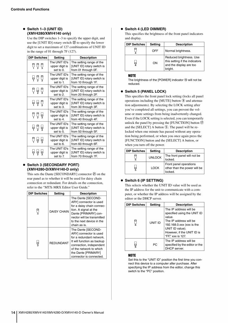
XMV4280/XMV4140/XMV4280-D/XMV4140-D Owner’s ManualSwitch 1–3 (UNIT ID)
(XMV4280/XMV4140 only)
Use the DIP switches 1–3 to specify the upper digit, and use the [UNIT ID] rotary switch @2 to specify the lower digit to set a maximum of 127 combinations of UNIT ID in the range of 01 through 7F (127).
Switch 3 (SECONDARY PORT)
(XMV4280-D/XMV4140-D only)
This sets the Dante [SECONDARY] connector @1 on the rear panel as to whether it will be used for daisy chain connection or redundant. For details on the connection, refer to the “MTX-MRX Editor User Guide.”
Switch 4 (LED DIMMER)
This specifies the brightness of the front panel indicators and display.
Switch 5 (PANEL LOCK)
This specifies the front panel lock setting (locks all panel operations including the [MUTE] button o and attenua-tion adjustments). By selecting the LOCK setting after you’ve completed all settings, you can prevent the vol-ume or mute settings from being inadvertently changed.Even if the LOCK setting is selected, you can temporarily unlock the panel by pressing the [FUNCTION] button !7 and the [SELECT] A button t. The panel will be re-locked when one minute has passed without any opera-tion being performed, or when you once again press the [FUNCTION] button and the [SELECT] A button, or when you turn off the power.
Switch 6 (IP SETTING)
This selects whether the UNIT ID value will be used as the IP address for the unit to communicate with a com-puter, or whether the IP address will be assigned by the editor or the DHCP server.
DIP Switches Setting Description
The UNIT ID’s upper digit is
set to 0.
The setting range of the [UNIT ID] rotary switch is from 01 through 0F.
The UNIT ID’s upper digit is
set to 1.
The setting range of the [UNIT ID] rotary switch is from 10 through 1F.
The UNIT ID’s upper digit is
set to 2.
The setting range of the [UNIT ID] rotary switch is from 20 through 2F.
The UNIT ID’s upper digit is
set to 3.
The setting range of the [UNIT ID] rotary switch is from 30 through 3F.
The UNIT ID’s upper digit is
set to 4.
The setting range of the [UNIT ID] rotary switch is from 40 through 4F.
The UNIT ID’s upper digit is
set to 5.
The setting range of the [UNIT ID] rotary switch is from 50 through 5F.
The UNIT ID’s upper digit is
set to 6.
The setting range of the [UNIT ID] rotary switch is from 60 through 6F.
The UNIT ID’s upper digit is
set to 7.
The setting range of the [UNIT ID] rotary switch is from 70 through 7F.
DIP Switches Setting Description
DAISY CHAIN
The Dante [SECOND-ARY] connector is used for a daisy chain connec-tion. A signal at the Dante [PRIMARY] con-nector will be transmitted to the next device in the chain as is.
REDUNDANT
The Dante [SECOND-ARY] connector is used for a redundant network. It will function as backup connection, independent of the network to which the Dante [PRIMARY] connector is connected.
DIP Switches Setting Description
OFF Normal brightness.
ON
Reduced brightness. Use this setting if the indicators and the display are too bright.
NOTEThe brightness of the [POWER] indicator !0 will not be reduced.
DIP Switches Setting Description
UNLOCKThe front panel will not be locked.
LOCKFront panel operations other than the power will be locked.
DIP Switches Setting Description
UNIT ID
The IP address will be specified using the UNIT ID value.The IP address will be 192.168.0.xxx (xxx is the UNIT ID value).However, if the UNIT ID is “FF,” xxx is 127.
PCThe IP address will be specified by the editor or the DHCP server.
NOTESet this to the “UNIT ID” position the first time you con-nect this device to a computer after purchase. After specifying the IP address from the editor, change this switch to the “PC” position.
Controls and Functions
5
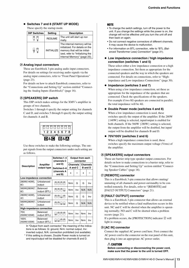
XMV4280/XMV4140/XMV4280-D/XMV4140-D Owner’s Manual 1Switches 7 and 8 (START UP MODE)
These specify the startup mode.
@4 Analog input connectors
These are Euroblock 3-pin analog audio input connectors.For details on settings for receiving audio signals via the analog input connectors, refer to “Front Panel Operations” (page 23).For details on how to attach Euroblock connectors, refer to the “Connections and Setting Up” section entitled “Connect-ing the Analog Inputs (Euroblock)” (page 16).
@5 [SPEAKERS] DIP switch
This DIP switch makes settings for the XMV’s amplifier in groups of two channels.Switches 1 through 4 specify the output setting for channels C and D, and switches 5 through 8 specify the output setting for channels A and B.
Use these switches to make the following settings. The out-put signals from the output connectors under each setting are as follows.
In “Output from each connector,” the meaning of the indica-tions is as follows: G: ground, Nrm: normal output, Inv: inverted output, N/A: connection prohibited (not available).
* If this setting is chosen, Double Power mode is turned on and input/output will be disabled for channels B and D.
Low impedance connection / high impedance
connection (switches 1 and 5)
These select either a low impedance connection or a high impedance connection. Set them as appropriate for the connected speakers and the way in which the speakers are connected. For details on connections, refer to “High-impedance and Low-impedance Connections” (page 30).
Impedance (switches 3 and 7)
When using a low impedance connection, set these as appropriate for the impedance of the speakers that are connected. Check the specifications of the speakers.For example if two 8Ω speakers are connected in parallel, the total impedance will be 4Ω.
Double Power mode (switches 4 and 8)
When a low impedance connection is used, these switches specify the output of the amplifier. If the 280W {140W} setting is selected, input/output is enabled for both channels. If the 560W {280W} setting is selected, the output from the amplifier will be doubled, but input/output will be disabled for channels B and D.
70V/100V (switches 2 and 6)
When a high impedance connection is used, these switches specify the maximum output voltage (Vrms) of the amplifier.
@6 [SPEAKERS] output connectors
These are barrier strip type speaker output connectors. For details on how to make connections to a barrier strip, refer to the “Connections and Setting Up” section entitled “Connect-ing Speaker Cables” (page 18).
@7 [REMOTE] connector
This is a Euroblock 3-pin connector that allows muting/unmuting of all channels and power-on/standby to be con-trolled remotely. For details, refer to “[REMOTE] and [FAULT OUTPUT] Connectors” (page 21).
@8 [FAULT OUTPUT] connector
This is a Euroblock 3-pin connector that allows an external device to be notified when a fatal malfunction occurs in this unit. NC and C will be shorted when the amplifier is operat-ing normally; NO and C will be shorted when a problem occurs (page 21).If a problem occurs, the [PROTECTION] indicator w will light in orange.
@9 [AC IN] connector
Connect the supplied AC power cord here. First connect the AC power cord to the connector on the rear panel of this unit, then plug it into an appropriate AC power outlet.
DIP Switches Setting Description
RESUMEThe unit will start up nor-mally.
INITIALIZE
The internal memory will be initialized. For details on the memory that will be initial-ized, refer to “Initializing the Internal Memory” (page 25).
DescriptionAmplifier
output type
Switches 1–4
(channels C
and D)
Switches 5–8
(channels A
and B)
Output from each
connector
Channels
A and C
Channels
B and D
+ – + –
Low-impedance connection
280W{140W}, 8Ω
Unbalanced output
Nrm G G Inv
560W{280W}*, 8Ω
Balanced output (BTL)
Nrm Inv N/A N/A
280W{140W}, 4Ω
Unbalanced output
Nrm G G Inv
560W{280W}*, 4Ω
Unbalanced output
Nrm G N/A N/A
High-impedance connection
70V, 250W{125W}
Balanced output (BTL)
Nrm Inv Nrm Inv
100V, 250W{125W}
Balanced output (BTL)
Nrm Inv Nrm Inv
NOTE• To change the switch settings, turn off the power to the
unit. If you change the settings while the power is on, the change will not be effective until you turn the unit off and then back on again.
• Do not connect negative connectors of different channels. It may cause the device to malfunction.
• For information on BTL connection, refer to “BTL (Bal-anced Transformer Less) Connection” (page 31).
CAUTIONBefore connecting or disconnecting the power cord,
make sure that the power to the unit is turned OFF.

16
Connections and Setting Up
XMV4280/XMV4140/XMV4280-D/XMV4140-D Owner’s Manual
This chapter explains how to set up the XMV to input analog signals.
If you are using the XMV along with the MTX, refer to the “MTX Setup Manual.” Refer to this manual for details regard-ing the following items, even if you are using the XMV along with the MTX.
• Making settings for speaker output• Connecting the speaker output connectors• Making high pass filter (HPF) settings• Lowering the brightness of the indicators and the display• Locking the panel
Here we will make and verify the input/output settings as out-lined below.
Rack-mounting the UnitRefer to “Precautions for Rack Mounting” (page 8), and mount the XMV in your rack.
Checking the Device Setup DIP Switch Set-tingsMake sure that all of the rear panel’s device setup DIP switches (page 13) are in the upward position.
Connecting the Analog Inputs (Euroblock)Connect the analog outputs of your mixer or other device to the analog input connectors (page 15).You must use the supplied Euroblock plugs with tabs.If these have been lost, please contact your Yamaha dealer.
Setup for Analog Signal Input
Explanation Page
Rack-mounting the Unit 16
Checking the Device Setup DIP Switch Settings 16
Connecting the Analog Inputs (Euroblock) 16
Making Settings for Speaker Output 17
Connecting Speaker Cables 18
Connecting the Power Cord 19
Turning the Power On 19
Enabling Analog Input 19
Making High Pass Filter (HPF) Settings 19
Checking the Wiring 20
Lowering the Brightness of the Indicators and the Display
20
Locking the Front Panel 20
CAUTIONSteps earlier than “Turning the Power On” must be per-
formed with the power off. If you perform these steps with
the power on, the settings might not be applied, or you
might be subject to electrical shock if you touch the con-
nectors.
1 2 3 4 5 6 7 8
Cable preparation
• To prepare the cable for attachment to a Euroblock connector, strip the wire as shown in the illustration using stranded wire to make connections. With a Euroblock connection, stranded wires may be prone to breakage because of metal fatigue due to the weight of the cable or due to vibration. Bundle the cables and the Euroblock tabs using the supplied cable ties (page 17). When rackmounting your equipment, use a lacing bar when possible to bun-dle and fasten the cables.
• If cables will be frequently connected and discon-nected, as in the case of a portable installation, we recommend that you use ferrules with insulation sleeves. Use a ferrule whose conductor portion has an external diameter of 1.6 mm or less, and a length of approximately 7 mm (such as the AI0,5-6WH made by the Phoenix Contact corporation).
approx.7 mm
approx.20 mm
NOTEDo not tin (plate with solder) the exposed end.
1.6 mm or lessapprox.7 mm
Connections and Setting Up
7
XMV4280/XMV4140/XMV4280-D/XMV4140-D Owner’s Manual 11. Loosen terminal screws.
2. Insert cables.
3. Securely tighten terminal screws.
Pull the cables (not too strongly) to confirm that they are securely connected.
4. Bundle the cables and the Euroblock tab
using the supplied cable tie.
5. Insert the Euroblock plug into the Analog
input connector of the device.
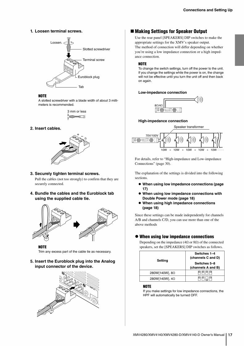
Making Settings for Speaker OutputUse the rear panel [SPEAKERS] DIP switches to make the appropriate settings for the XMV’s speaker output.The method of connection will differ depending on whether you’re using a low impedance connection or a high imped-ance connection.
Low-impedance connection
High-impedance connection
For details, refer to “High-impedance and Low-impedance Connections” (page 30).
The explanation of the settings is divided into the following sections.
When using low impedance connections (page
17)
When using low impedance connections with
Double Power mode (page 18)
When using high impedance connections
(page 18)
Since these settings can be made independently for channels A/B and channels C/D, you can use more than one of the above methods
When using low impedance connectionsDepending on the impedance (4Ω or 8Ω) of the connected speakers, set the [SPEAKERS] DIP switches as follows.
NOTEA slotted screwdriver with a blade width of about 3 milli-meters is recommended.
NOTETrim any excess part of the cable tie as necessary.
Loosen.
Slotted screwdriver
Terminal screw
Euroblock plug
Tab
3 mm or less
+ –G
NOTETo change the switch settings, turn off the power to the unit. If you change the settings while the power is on, the change will not be effective until you turn the unit off and then back on again.
Setting
Switches 1–4
(channels C and D)
Switches 5–8
(channels A and B)
280W{140W}, 8Ω
280W{140W}, 4Ω
NOTEIf you make settings for low impedance connections, the HPF will automatically be turned OFF.
8Ω/4Ω
10W 10W 10W 10W 10W
70V/100V
Speaker transformer
Connections and Setting Up
18
XMV4280/XMV4140/XMV4280-D/XMV4140-D Owner’s ManualThe XMV features a switch function between 8Ω and 4Ω to guarantee the output in case it is connected to a speaker with an impedance of 8Ω or higher.If you connect a speaker with an impedance of 8Ω or higher, set the [SPEAKERS] DIP switches to 8Ω. If you connect a speaker with an impedance of 4Ω or higher, but lower than 8Ω, set the [SPEAKERS] DIP switches to 4Ω.
When using low impedance connections with Double Power modeIf you use Double Power mode, input/output will be dis-abled for channels B and D.Depending on the impedance (4Ω or 8Ω) of the connected speakers, set the [SPEAKERS] DIP switches as follows.
When using high impedance connectionsDepending on the specifications (70V or 100V) of the system in which this unit is being installed, set the [SPEAKERS] DIP switches as follows.
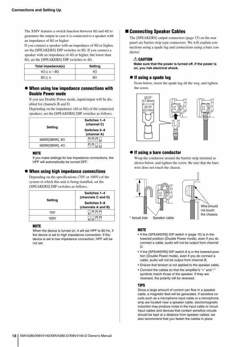
Connecting Speaker CablesThe [SPEAKERS] output connectors (page 15) on the rear panel are barrier strip type connectors. We will explain con-nections using a spade lug and connections using a bare con-ductor.
If using a spade lugFrom below, insert the spade lug all the way, and tighten the screw.
If using a bare conductorWrap the conductor around the barrier strip terminal as shown below, and tighten the screw. Be sure that the bare wire does not touch the chassis.
Total impedance(x) Setting
4Ω x 8Ω 4Ω
8Ω x 8Ω
Setting
Switches 1–4
(channel C)
Switches 5–8
(channel A)
560W{280W}, 8Ω
560W{280W}, 4Ω
NOTEIf you make settings for low impedance connections, the HPF will automatically be turned OFF.
Setting
Switches 1–4
(channels C and D)
Switches 5–8
(channels A and B)
70V
100V
NOTEWhen the device is turned on, it will set HPF to 80 Hz, if the device is set to high impedance connection. If the device is set to low impedance connection, HPF will be not set.
CAUTIONMake sure that the power is turned off. If the power is
on, you risk electrical shock.
NOTE• If the [SPEAKERS] DIP switch 4 (page 15) is in the
lowered position (Double Power mode), even if you do connect a cable, audio will not be output from channel D.
• If the [SPEAKERS] DIP switch 8 is in the lowered posi-tion (Double Power mode), even if you do connect a cable, audio will not be output from channel B.
• Ensure that tension is not applied to the speaker cable.
• Connect the cables so that the amplifier’s “+” and “-” symbols match those of the speaker. If they are reversed, the polarity will be reversed.
TIPSSince a large amount of current can flow in a speaker cable, a magnetic field will be generated. If sensitive cir-cuits such as a microphone input cable or a microphone amp are located near a speaker cable, electromagnetic induction may produce noise in the input cable or circuit. Input cables and devices that contain sensitive circuits should be kept at a distance from speaker cables; we also recommend that you fasten the cables in place.
>0.15"(>3.7mm)
<0.31"(<7.8mm)
==
==
15m
m*
* Actual size Speaker cable
Wire should not touch the chassis.
Connections and Setting Up
9
XMV4280/XMV4140/XMV4280-D/XMV4140-D Owner’s Manual 1Connecting the Power CordConnect the included power cord to the [AC IN] connector (page 15) on the rear panel. First connect the AC power cord to the connector on this unit, then plug it into an appropriate AC power outlet.
Turning the Power OnUse the front panel power switch (page 9) to turn the power on.
Enabling Analog InputUsing the front panel, enable analog input as follows.
1. While holding down the [FUNCTION] but-
ton, turn the encoder to make the display
indicate “SRC.”
The control mode will change to “Analog/digital input selection.”
2. Press the [SELECT] button of the channel
for which you want to enable the analog
input.
The [SELECT] indicator of the selected channel will light.
3. Take your finger off the [FUNCTION] button,
and turn the encoder to make the display
indicate “ANA.”
Input from the analog input connectors will be enabled.
Making High Pass Filter (HPF) SettingsIf the unit is set for low impedance connections, the HPF will be OFF. If the unit is set for high impedance connec-tions, the 80 Hz HPF will be enabled.If you want to change this setting, proceed as follows.
1. While holding down the [FUNCTION] but-
ton, turn the encoder to make the display
indicate “HPF.”
The control mode will change to “HPF.”
2. Press the [SELECT] button of the channel
for which you want to make HPF settings.
The [SELECT] indicator of the channel whose HPF you are setting will light.
3. Turn the encoder to select the desired HPF
setting.
The available HPF settings are OFF / 40 Hz / 80 Hz.
CAUTIONYou must turn off the power before connecting the
power cord.
CAUTIONBefore you turn the power on, make sure that audio
signals are not being input to the analog input connec-
tors. If audio signals are being input, excessive input
will be applied to the speakers when the power is
turned on, possibly damaging the speaker system or
damaging your hearing by high-volume sound. If there
is a problem with the speakers or the wiring, the pro-
tection circuit will operate immediately when the power
is turned on. Check whether there might be a problem
with the wiring.
NOTEIf a certain period of time elapses without any operation being performed, the unit will return to Attenuation set-ting operating mode.
NOTE• In order to protect the amplifier, the HPF cannot be
turned OFF if high impedance connections are used.
• If you’re using a sub-woofer with high-impedance con-nections, we recommend that you change the HPF setting to 40 Hz.
• If you’re using a full-range speaker with high-imped-ance connections, the amplifier’s protection circuit may operate if the HPF is set to other than 80 Hz. We rec-ommend that you use the 80 Hz setting.
• If a certain period of time elapses without any opera-tion being performed, the unit will be placed in Attenua-tion setting operating mode.
NOTEIf the device is set as follows, the HPF settings will be changed automatically.
Previous
startupCurrent startup
HPF[SPEAKERS]
DIP switches
(page 15)
Device setup
DIP switches 7
and 8 (page 15)
[SPEAKERS]
DIP switches
(page 15)
Hi impedance
RESUME
Low impedance (changed)
Off
Hi impedance (not changed)
Same as the previ-
ous startup
Low impedance
Low impedance (not changed)
Same as the previ-
ous startup
Hi impedance (changed)
80 Hz
(Unrelated to the setting at
previous startup)
INITIALIZELow impedance Off
Hi impedance 80 Hz
Connections and Setting Up
20
XMV4280/XMV4140/XMV4280-D/XMV4140-D Owner’s ManualChecking the WiringHere we’ll explain how to change the attenuation settings and switch muting on/off, which you will need to do when checking the wiring.Before you check the wiring, we recommend that you set the attenuator of all channels to the lowest setting (-99 dB) to prevent speaker damage.To check the wiring, you’ll need to be outputting an audio signal from the mixer or other device that’s connected to the analog input connectors.
Changing the attenuator settingHere’s how to change the attenuator setting.
1. While holding down the [FUNCTION] but-
ton, turn the encoder to make the display
indicate “ATT.”
2. Press the [SELECT] button of the channel
whose setting you want to adjust.
The [SELECT] indicator of the selected channel will light.
3. Turn the encoder to gradually raise the
attenuator setting from -99, and verify
that sound is produced from the speaker.
Switching the mute setting on/off
While holding down the [MUTE] button,
press the [SELECT] button of the channel
that you want to control.
When mute is on, the [MUTE] indicator will light; when mute is off, the [MUTE] indicator will be unlit.
Lowering the Brightness of the Indicators and the DisplayIf the front panel LED indicators are too bright, you can lower their brightness.After turning the power off, set the rear panel device setup DIP switch 4 (LED DIMMER) to the lower position (ON). The next time you turn the power on, the unit will start up with decreased indicator brightness.
Locking the Front PanelBy locking the panel you can disable front panel operations other than controlling the power (front panel lock).When this unit is used as part of an installed system, you can lock down the settings by disabling operations from the front panel, thus preventing inadvertent changes.After turning the power off, set the rear panel device setup DIP switch 5 (PANEL LOCK) to the lower position (LOCK). The next time you turn the power on, the unit will start up with the front panel locked.Even in the locked state, you can temporarily defeat the panel lock by pressing the [FUNCTION] button and the [SELECT] A button. However, it will be re-locked when any of the following conditions occur.
• One minutes elapses without any operation being per-formed after the panel is temporarily unlocked
• You press the [FUNCTION] button and the [SELECT] A button
• You turn the power off
The lock status is shown by the front panel [PANEL LOCK] indicator.
• Locked: lit• Not locked: unlit• Temporarily unlocked: flashing
NOTE If the speakers are remotely located and you are unable to check the signal output easily, changing the [SIGNAL] indi-cator (page 10) setting to “output” will allow you to check whether current is flowing to the speakers. For details on switching the indicator setting, refer to “Front Panel Opera-tions” (page 23).
NOTEThe brightness of the [POWER] indicator will not be reduced.
Connections and Setting Up
1
XMV4280/XMV4140/XMV4280-D/XMV4140-D Owner’s Manual 2This chapter explains how to use and connect the [REMOTE] connector and [FAULT OUTPUT] connector located on the rear panel of the XMV.
Using the [REMOTE] Connector (Euroblock 3-pin)
You can connect switches to the rear panel [REMOTE] connec-tor (page 15), and use them to remotely mute/unmute all chan-nels or switch the power standby/on status.From the left, the [REMOTE] connector consists of MUTE ALL, STANDBY, and GND pins.The [REMOTE] connector uses a Euroblock plug.For details on how to connect Euroblock plugs, refer to “Con-necting the [REMOTE] Connector or [FAULT OUTPUT] Con-nector” (page 22).
• Muting/unmuting all channels
• Switching the power standby/on status
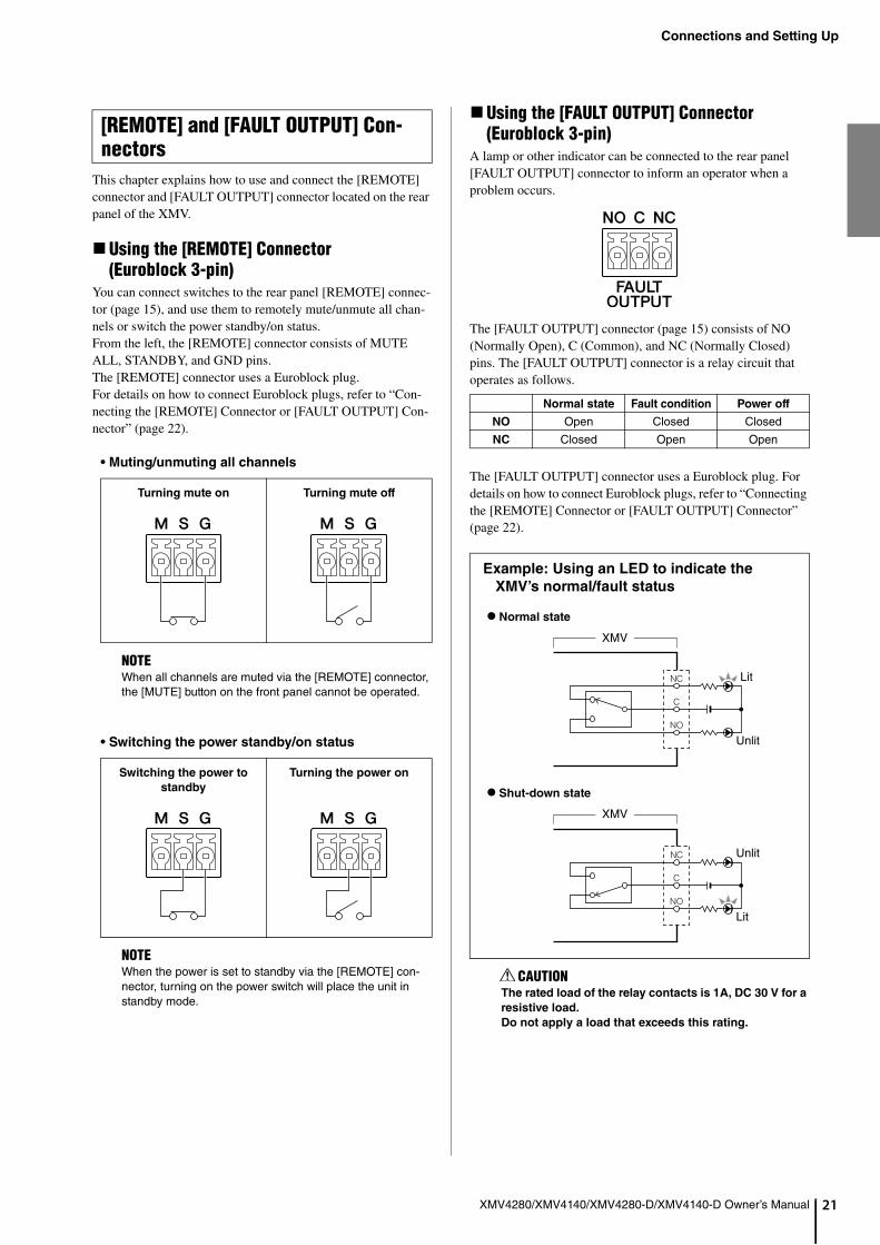
Using the [FAULT OUTPUT] Connector (Euroblock 3-pin)
A lamp or other indicator can be connected to the rear panel [FAULT OUTPUT] connector to inform an operator when a problem occurs.
The [FAULT OUTPUT] connector (page 15) consists of NO (Normally Open), C (Common), and NC (Normally Closed) pins. The [FAULT OUTPUT] connector is a relay circuit that operates as follows.
The [FAULT OUTPUT] connector uses a Euroblock plug. For details on how to connect Euroblock plugs, refer to “Connecting the [REMOTE] Connector or [FAULT OUTPUT] Connector” (page 22).
[REMOTE] and [FAULT OUTPUT] Con-nectors
Turning mute on Turning mute off
NOTEWhen all channels are muted via the [REMOTE] connector, the [MUTE] button on the front panel cannot be operated.
Switching the power to
standby
Turning the power on
NOTEWhen the power is set to standby via the [REMOTE] con-nector, turning on the power switch will place the unit in standby mode.
Normal state Fault condition Power off
NO Open Closed Closed
NC Closed Open Open
Example: Using an LED to indicate the
XMV’s normal/fault status
CAUTIONThe rated load of the relay contacts is 1A, DC 30 V for a
resistive load.
Do not apply a load that exceeds this rating.
C
NC
NO
C
NC
NO
Normal state
Shut-down state
Lit
Unlit
Unlit
Lit
XMV
XMV

Connections and Setting Up
22
XMV4280/XMV4140/XMV4280-D/XMV4140-D Owner’s ManualConnecting the [REMOTE] Connector or [FAULT OUTPUT] Connector
You must use the supplied Euroblock plugs when making con-nections to the [REMOTE] connector or [FAULT OUTPUT] connector.If these have been lost, please contact your Yamaha dealer.
1. Loosen terminal screws.
2. Insert cables.
3. Securely tighten terminal screws.
Pull the cables (not too strongly) to confirm that they are securely connected.
4. Insert the Euroblock plug into the [REMOTE]
connector or [FAULT OUTPUT] connector of
the device.
Cable preparation
• To prepare the cable for attachment to a Euroblock connector, strip the wire as shown in the illustration using stranded wire to make connections. With a Euro-block connection, stranded wires may be prone to breakage because of metal fatigue due to the weight of the cable or due to vibration.
• If cables will be frequently connected and discon-nected, as in the case of a portable installation, we recommend that you use ferrules with insulation sleeves. Use a ferrule whose conductor portion has an external diameter of 1.3 mm or less, and a length of approximately 5 mm (such as the AI0,5-6WH made by the Phoenix Contact corporation).
NOTEA slotted screwdriver with a blade width of about 3 millime-ters is recommended.
approx.5 mm
NOTEDo not tin (plate with solder) the exposed end.
1.3 mm or lessapprox.5 mm
Loosen.
Terminalscrew
Slotted screwdriver
Euroblock plug
3 mm or less
Operations
3
XMV4280/XMV4140/XMV4280-D/XMV4140-D Owner’s Manual 2This chapter describes the operations you can perform from the front panel.
Basic Operations
*1: “X+Y” means “operate Y while operating X.” For example, “[SELECT] A + encoder” means that you should hold down the [SELECT] A button and operate the encoder.
Front Panel Operations
NOTEIf you modify the parameter settings, do not turn the power switch OFF for at least one second. Otherwise, the changes to the settings may be lost.
To do this... Operation Description
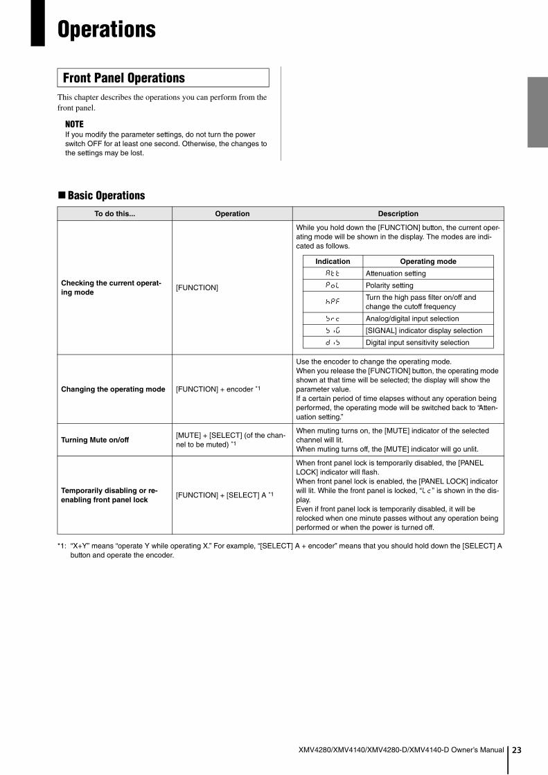
Checking the current operat-
ing mode[FUNCTION]
While you hold down the [FUNCTION] button, the current oper-ating mode will be shown in the display. The modes are indi-cated as follows.
Changing the operating mode [FUNCTION] + encoder *1
Use the encoder to change the operating mode.When you release the [FUNCTION] button, the operating mode shown at that time will be selected; the display will show the parameter value.If a certain period of time elapses without any operation being performed, the operating mode will be switched back to “Atten-uation setting.”
Turning Mute on/off[MUTE] + [SELECT] (of the chan-nel to be muted) *1
When muting turns on, the [MUTE] indicator of the selected channel will lit.When muting turns off, the [MUTE] indicator will go unlit.
Temporarily disabling or re-
enabling front panel lock[FUNCTION] + [SELECT] A *1
When front panel lock is temporarily disabled, the [PANEL LOCK] indicator will flash.When front panel lock is enabled, the [PANEL LOCK] indicator will lit. While the front panel is locked, “LC” is shown in the dis-play.Even if front panel lock is temporarily disabled, it will be relocked when one minute passes without any operation being performed or when the power is turned off.
Indication Operating mode
ATT Attenuation setting
POL Polarity setting
HPFTurn the high pass filter on/off and change the cutoff frequency
SRC Analog/digital input selection
SIG [SIGNAL] indicator display selection
DIS Digital input sensitivity selection

Operations
24
XMV4280/XMV4140/XMV4280-D/XMV4140-D Owner’s ManualParameter Operations
*2: “XY” means “operate X, and then operating Y.” For example, “[SELECT] A encoder” means that you should press the [SELECT] A, and then operate the encoder.
To do this...Operating mode
(indication)Operation Description
Changing the attenuator
value (volume)
attenuator(ATT)
[SELECT] (of the channel to be changed) encoder *2
The [SELECT] indicator of the selected channel will lit, and the attenuator value can be edited by the encoder.The range of adjustment is -99 dB–0 dB in 1 dB steps.
Changing the polaritypolarity(POL)
[SELECT] (of the channel to be changed) encoder *2
The [SELECT] indicator of the selected channel will light, and the polarity can be changed by using the encoder.
Changing the high pass fil-
ter (HPF) cutoff frequency
Turning off the high pass
filter (HPF)
HPF(HPF)
[SELECT] (of the channel to be changed) encoder *2
The [SELECT] indicator of the selected channel will light, and the high pass filter (HPF) on/off set-ting and cutoff frequency can be changed by using the encoder. This will be set to 80 Hz if a high impedance connection is specified; it will be turned OFF if a low impedance connection is specified.
In order to protect the amplifier, the HPF of the selected channel cannot be turned OFF if a high impedance connection is specified.
Switching between analog/
digital input
analog/digital input selection(SRC)
Encoder operation
The [SELECT] indicator of the selected channel will light, and you can use the encoder to change the analog/digital input selection.
Do not select “analog” if your audio network has been configured using the [YDIF] connectors or Dante [PRIMARY]/[SECONDARY] connectors.Selecting “analog” will interrupt audio transmission to and from the devices that are connected via the YDIF connectors or Dante connectors.
Switching whether the
[SIGNAL] indicators are
used for input or for output
[SIGNAL] indicator switching(SIG)
Encoder operation
Use the encoder to specify whether the [SIGNAL] indicators will show the input signal level or the out-put signal level.
Digital input sensitivity
selection
* Digital input sensitivity: the digital input level at which the input attenuator is 0 dB (volume maximum) and the amplifier is at maximum output; refer to “Block Dia-gram” (page 236).
digital input sensitivity(DIS)
Encoder operation
Use the encoder to change the digital input sensi-tivity setting. To prevent inadvertent setting, the value does not change right away when the encoder is turned. Until the input sensitivity changes, “– – – ” appears in the display.
Indication Polarity
NOR Normal polarity
INV Inverted polarity
Indication Meaning
OFF HPF is off
H40 Cutoff frequency is 40 Hz
H80 Cutoff frequency is 80 Hz
Indication Input connectors
ANA Analog input connectors
DIG
[YDIF] connectors (XMV4280/XMV4140)
Dante [PRIMARY]/[SECONDARY] connectors (XMV4280-D/XMV4140-D)
Indication Lit condition
IN Input
OUT Output
Indication Digital input sensitivity
D20 -20 dBFS
D03 -3 dBFS
– – –(value in process of being changed)

Operations
5
XMV4280/XMV4140/XMV4280-D/XMV4140-D Owner’s Manual 2Execute the following procedure when you return the internal memory settings to their factory set state (initialize the internal memory), such as when the amplifier has been moved to a dif-ferent location.
1. Turn off the power.
2. Set device setup DIP switch 7 to the down-
ward position and switch 8 to the upward
position.
3. Turn on the power. The initializing operation
will start.
• In the case of the XMV4280/XMV4140
During initialization, the [NETWORK], [YDIF], and [PANEL LOCK] indicators will flash. When initialization is complete, the [NETWORK] and [YDIF] indicators will flash.
• In the case of the XMV4280-D/XMV4140-D
During initialization, the [PRIMARY], [SECONDARY], [SYNC] (green), [SYNC] (orange) and [PANEL LOCK] indicators will flash. When initialization is complete, the [PRIMARY], [SECONDARY] and [SYNC] (green) indi-cators will flash.
If the unit fails to initialize, the [POWER] indicator will light, the [ALERT] indicator will flash, and other indica-tors will turn off. Please contact your Yamaha dealer.
4. Make sure the initializing operation is com-
plete and turn off the power.
5. Set device setup DIP switches 7 and 8 to the
upward position (RESUME).
6. Turn on the power.
The following parameters held in memory are initialized.
• Attenuator values• Polarity settings• HPF settings• Analog/digital input setting• [SIGNAL] indicator display setting• Event log
* When the unit is shipped from the factory, the device setup DIP switches are all in the upward position.
Initializing the Internal Memory

26
Appendix
XMV4280/XMV4140/XMV4280-D/XMV4140-D Owner’s Manual
* If taking the above steps does not solve the problem, contact your Yamaha dealer for repair.
The Yamaha Pro Audio website provides a FAQ (a list of frequently asked questions, with answers).http://www.yamahaproaudio.com/
Troubleshooting
Symptom Possible causes Possible solution
The power won’t turn on The power cord is disconnected Connect the power cord.
No sound is heard
The analog/digital input setting is incorrect
From the front panel, check the analog/digital input setting.
Double Power mode is selectedIn Double Power mode, no audio signals will be output from channel B or channel D. Either turn off Double Power mode, or re-connect the cables.
An input/output cable is discon-nected
Connect the input/output cables. Also, make sure that the cables are securely connected.
The mute function is turned onMake sure that the [MUTE] indicator is unlit. If it is lit, turn Mute off.
The attenuator value is too lowChange to “Attenuation setting” (page 23), and check whether the attenuator value is appropriate on the display (page 10).
No audio signal is being inputMake sure that an audio signal is being output from the mixer or other device that is outputting audio to the XMV.
The protection circuit has operated(the [PROTECTION] indicator is lit)
Turn off the power, wait for the XMV to cool, and then turn the power on again.
The unit is in standby mode(the [POWER] indicator is flashing)
Make sure that the switch connected to the [REMOTE] connector is turned on. Alternatively, use the editor to check that this is turned on.
Some abnormality has occurred at digital input from the MTX(on XMV4280/XMV4140: [YDIF] indicator is unlit; on XMV4280-D/XMV4140-D: green [SYNC] indica-tor is unlit)
Check the MTX. For details, refer to MTX manu-als.
“Analog” input has been selected on a device that is connected via a YDIF connector(XMV4280/XMV4140 only)
Select “digital” input on the device. If you wish to use the device for analog input, disconnect the device from the YDIF network.
The [ALERT] indicator remains flashing or lit even after you’ve turned the power on/off
The device has failedThe device has failed. Contact your Yamaha dealer for repair.

Appendix
7
XMV4280/XMV4140/XMV4280-D/XMV4140-D Owner’s Manual 2If a problem occurs in the XMV, the [ALERT] indicator will flash and an alert number will appear in the display.The alert numbers, the corresponding content, and the appropriate actions are listed below.
Alert Numbers and Content
Alert number Meaning Response
No display(only [ALERT] is lit)
The device has not started up correctly.
Turn the power off, then turn on after waiting at least 5 seconds. If this does not solve the problem, please ini-tialize the memory. Should this also fails, contact your Yamaha dealer.001.–008.
010.The internal backup battery has been completely exhausted or is not installed. When you turn off the power, the current settings will be
lost, and will return to the default values. Please stop use immediately, and contact your Yamaha dealer.011.
The internal backup battery has run extremely low, and it is possible that the internal memory has been cleared.
012.The internal backup battery has only a small amount of power remaining.
This does not affect the operation of the device. How-ever, if you continue using the device, the settings may be lost and reset to the default values. Contact your Yamaha dealer as soon as possible.
013.A problem has occurred with the internal clock, and it has been initialized (January 1, 2000, 0:00)
If this occurs each time you turn on the power, it is possi-ble that the internal backup battery has run down or that the device has malfunctioned. Contact your Yamaha dealer.If this occurs only once, an abnormality was detected with the clock setting and it was initialized; use the editor to set the time.
015. The settings saved in internal memory have been lost.Either the internal backup battery has run low, or the device has malfunctioned. Contact your Yamaha dealer.
016. A memory problem has occurred. Contact your Yamaha dealer.
021. The word clock master has become unlocked.Make sure that the word clock signal is being input cor-rectly.
022.The digital signal being input to the [YDIF IN] connector is not synchronized to the word clock of this device.
Make sure that YDIF cables are properly connected.Use cables that meet the required specifications.
023.The digital signal being input to the [YDIF IN] connector is not continuously synchronized to the word clock of this device.
030.There is a problem with the connection of the [YDIF IN] connector.
Make sure that YDIF cables are properly connected.Use cables that meet the required specifications.
040. Duplicate IP addresses.Change the IP addresses so that there are no dupli-cates.
041. IP address was not set within 60 seconds of startup.Please check rear panel DIP switch 6 (IP Setting). If DIP switch 6 is set to “PC,” use the editor or DHCP server to specify the device IP address.
043. Too many devices are connected to the network.Reduce the number of devices connected to the net-work.
046. Dante transmission flow count exceeded the limit.Maximum Dante Flow rate exceeded. Try changing parts of transmission flows to Multicast using Dante Controller.
050. The UNIT ID is set to “00.” Set the UNIT ID to something other than “00.”
051.Devices with identical UNIT IDs were found connected within the same network.
Change the UNIT ID so that there are no duplicates.
072.Because this device has Dante Device Lock enabled, the settings of device DIP switches and MTX-MRX Edi-tor do not match current Dante settings.
If you have Dante Device Lock enabled, please disable using Dante Controller, review device DIP switch settings and MTX-MRX Editor’s Dante settings, and edit as nec-essary to match the current situation.
100.The power supply was shut down because d.c. was detected on a speaker output.
It is likely that the device has malfunctioned; immediately stop using the device and contact your Yamaha dealer.
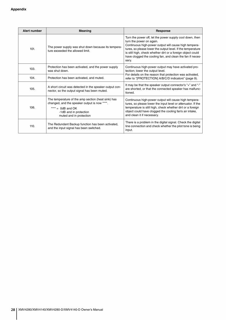
Appendix
28
XMV4280/XMV4140/XMV4280-D/XMV4140-D Owner’s Manual101.The power supply was shut down because its tempera-ture exceeded the allowed limit.
Turn the power off, let the power supply cool down, then turn the power on again.Continuous high-power output will cause high tempera-tures, so please lower the output level. If the temperature is still high, check whether dirt or a foreign object could have clogged the cooling fan, and clean the fan if neces-sary.
103.Protection has been activated, and the power supply was shut down.
Continuous high-power output may have activated pro-tection; lower the output level.For details on the reason that protection was activated, refer to “[PROTECTION] A/B/C/D indicators” (page 9).104. Protection has been activated, and muted.
105.A short circuit was detected in the speaker output con-nector, so the output signal has been muted.
It may be that the speaker output connector’s “+” and “-” are shorted, or that the connected speaker has malfunc-tioned.
106.
The temperature of the amp section (heat sink) has changed, and the speaker output is now ****.
**** = 0dB and OK-1dB and in protectionmuted and in protection
Continuous high-power output will cause high tempera-tures, so please lower the input level or attenuator. If the temperature is still high, check whether dirt or a foreign object could have clogged the cooling fan’s air intake, and clean it if necessary.
110.The Redundant Backup function has been activated, and the input signal has been switched.
There is a problem in the digital signal. Check the digital line connection and check whether the pilot tone is being input.
Alert number Meaning Response
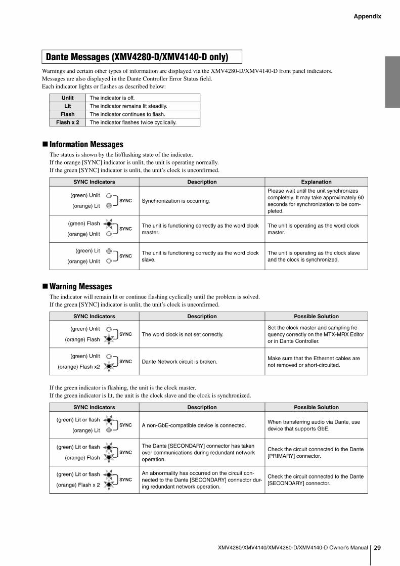
Appendix
9
XMV4280/XMV4140/XMV4280-D/XMV4140-D Owner’s Manual 2Warnings and certain other types of information are displayed via the XMV4280-D/XMV4140-D front panel indicators.Messages are also displayed in the Dante Controller Error Status field.Each indicator lights or flashes as described below:
Information MessagesThe status is shown by the lit/flashing state of the indicator.If the orange [SYNC] indicator is unlit, the unit is operating normally.If the green [SYNC] indicator is unlit, the unit’s clock is unconfirmed.
Warning MessagesThe indicator will remain lit or continue flashing cyclically until the problem is solved.If the green [SYNC] indicator is unlit, the unit’s clock is unconfirmed.
If the green indicator is flashing, the unit is the clock master.If the green indicator is lit, the unit is the clock slave and the clock is synchronized.
Dante Messages (XMV4280-D/XMV4140-D only)
Unlit The indicator is off.
Lit The indicator remains lit steadily.
Flash The indicator continues to flash.
Flash x 2 The indicator flashes twice cyclically.
SYNC Indicators Description Explanation
Synchronization is occurring.
Please wait until the unit synchronizes completely. It may take approximately 60 seconds for synchronization to be com-pleted.
The unit is functioning correctly as the word clock master.
The unit is operating as the word clock master.
The unit is functioning correctly as the word clock slave.
The unit is operating as the clock slave and the clock is synchronized.
SYNC Indicators Description Possible Solution
The word clock is not set correctly.Set the clock master and sampling fre-quency correctly on the MTX-MRX Editor or in Dante Controller.
Dante Network circuit is broken.Make sure that the Ethernet cables are not removed or short-circuited.
SYNC Indicators Description Possible Solution
A non-GbE-compatible device is connected.When transferring audio via Dante, use device that supports GbE.
The Dante [SECONDARY] connector has taken over communications during redundant network operation.
Check the circuit connected to the Dante [PRIMARY] connector.
An abnormality has occurred on the circuit con-nected to the Dante [SECONDARY] connector dur-ing redundant network operation.
Check the circuit connected to the Dante [SECONDARY] connector.
(green) Unlit
(orange) Lit
(green) Flash
(orange) Unlit
(green) Lit
(orange) Unlit
(green) Unlit
(orange) Flash
(green) Unlit
(orange) Flash x2
(green) Lit or flash
(orange) Lit
(green) Lit or flash
(orange) Flash
(green) Lit or flash
(orange) Flash x 2
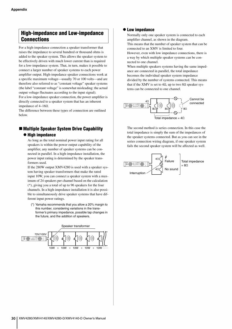
Appendix
30
XMV4280/XMV4140/XMV4280-D/XMV4140-D Owner’s ManualFor a high-impedance connection a speaker transformer that raises the impedance to several hundred or thousand ohms is added to the speaker system. This allows the speaker system to be effectively driven with much lower current than is required for a low-impedance system. That, in turn, makes it possible to connect a larger number of speaker systems to each power amplifier output. High-impedance speaker connections work at a specific maximum voltage—usually 70 or 100 volts—and are therefore also referred to as “constant voltage” speaker systems (the label “constant voltage” is somewhat misleading: the actual output voltage fluctuates according to the input signal).For a low-impedance speaker connection, the power amplifier is directly connected to a speaker system that has an inherent impedance of 4–16Ω.The difference between these types of connection are outlined below.
Multiple Speaker System Drive Capability High impedance
As long as the total nominal power input rating for all speakers is within the power output capability of the amplifier, any number of speaker systems can be con-nected in parallel. In a high-impedance installation, the power input rating is determined by the speaker trans-formers used.If the 280W output XMV4280 is used with a speaker sys-tem having speaker transformers that make the rated input 10W, you can connect a speaker system with a max-imum of 24 speakers per channel based on the calculation (*), giving you a total of up to 96 speakers for the four channels. In a high-impedance installation it is also possi-ble to simultaneously drive speaker systems that have dif-ferent input power ratings.
(*) Yamaha recommends that you allow a 20% margin to this number, considering variations in the trans-former’s primary impedance, possible tap changes in the future, and the addition of speakers.
Low impedanceNormally only one speaker system is connected to each amplifier channel, as shown in the diagram.This means that the number of speaker system that can be connected to an XMV is limited to four.However, even with low impedance connections, there is a way by which multiple speaker systems can be con-nected to one channel.When multiple speakers systems having the same imped-ance are connected in parallel, the total impedance becomes the individual speaker system impedance divided by the number of systems connected. This means that if the XMV is set to 4Ω, up to two 8Ω speaker sys-tems can be connected to one channel.
The second method is series connection. In this case the total impedance is simply the sum of the impedances of the speaker systems connected. But as you can see in the series connection wiring diagram, if one speaker system fails the second speaker system will be affected as well.
High-impedance and Low-impedance Connections
10W 10W 10W 10W 10W
70V/100V
Speaker transformer
4Ω
8Ω 8Ω 8Ω
Total impedance = 4Ω
Cannot be connected
4Ω
4ΩInterruption
Total impedance = 8Ω
Failure
No sound

Appendix
1
XMV4280/XMV4140/XMV4280-D/XMV4140-D Owner’s Manual 3Transmission Distance and EfficiencyThe cables that transmit electric signals have resistance. The resistance in short cables is small enough that it can be ignored, but as transmission distance and cable length increase, resistance can increase to the point that signal loss and degradation occur. That can mean reduced output level and sound quality. Below we examine the merits and demer-its of low-impedance and high-impedance connections in relation to transmission over significant distances.
High impedanceEven if the cable resistance reaches 8Ω due to an extended transmission distance, this is an amount that can be ignored relative to the impedance of the speaker sys-tem, meaning that transmission loss due to the cable will be insignificant, and thus will have little effect on the transmission efficiency of the electrical signal.
Low impedanceFor short distances over which cable resistance is insig-nificant, low-impedance connection allows the power amp to be directly connected to the speaker system with-out the need for speaker transformers. That means that the full performance potential of amp and speakers can be taken advantage of for sound quality that is superior to high-impedance installations. And since only one speaker system is usually connected to each amplifier channel, different audio signals can be sent to each speaker sys-tem, or “zone,” as required.But in a situation like the one shown in the diagram, where a long cable with a resistance of 8Ω is required, transmission loss will theoretically result in the output level being reduced by half because the impedance of the speaker system itself is only 8Ω. Half of the power gets absorbed by the cable, and only the remaining half is available to drive the speaker. So for low-impedance installations it is necessary to either keep the cables short enough that cable resistance is not an issue, or use thicker cables that have lower resistance for longer runs, for example.
BTL connection doubles the output power since the two ampli-fier channels are used as one amplifier.
70V/100VLong distance
Cable resistance (round-trip distance) = 8Ω
Speaker transformer (1kΩ)
Almost 100%
8ΩLong distance
Cable resistance (round-trip distance) = 8Ω
Speaker system inpedance = 8Ω
50%
BTL (Balanced Transformer Less) Con-nection
NOTESince the amplifier outputs are connected to both the plus con-nector and the minus connector, contact with the other connec-tors or the chassis may result in malfunction.
Normal amplifier
Inverted amplifier
Normal connection
BTL connection
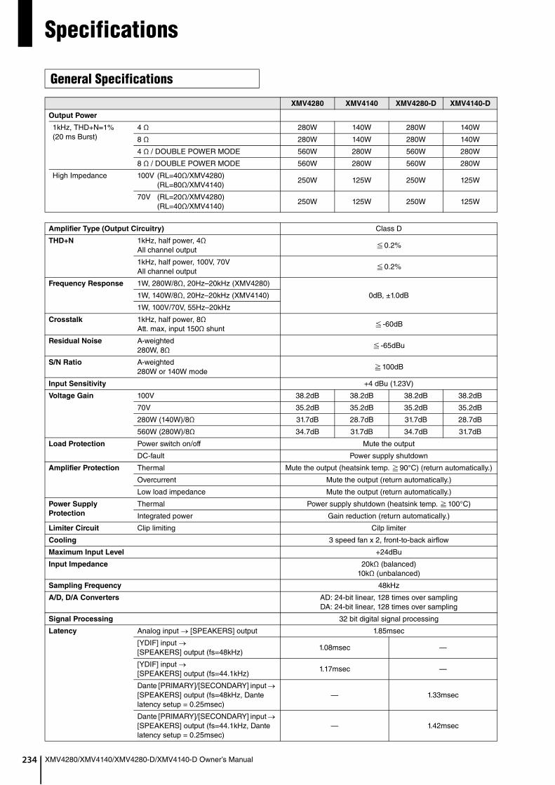
234
Specifications
XMV4280/XMV4140/XMV4280-D/XMV4140-D Owner’s Manual
General Specifications
XMV4280 XMV4140 XMV4280-D XMV4140-D
Output Power
1kHz, THD+N=1%(20 ms Burst)
4 Ω 280W 140W 280W 140W
8 Ω 280W 140W 280W 140W
4 Ω / DOUBLE POWER MODE 560W 280W 560W 280W
8 Ω / DOUBLE POWER MODE 560W 280W 560W 280W
High Impedance 100V (RL=40Ω/XMV4280) (RL=80Ω/XMV4140)
250W 125W 250W 125W
70V (RL=20Ω/XMV4280)(RL=40Ω/XMV4140)
250W 125W 250W 125W
Amplifier Type (Output Circuitry) Class D
THD+N 1kHz, half power, 4ΩAll channel output
0.2%
1kHz, half power, 100V, 70VAll channel output
0.2%
Frequency Response 1W, 280W/8Ω, 20Hz–20kHz (XMV4280)
0dB, ±1.0dB1W, 140W/8Ω, 20Hz–20kHz (XMV4140)
1W, 100V/70V, 55Hz–20kHz
Crosstalk 1kHz, half power, 8ΩAtt. max, input 150Ω shunt
-60dB
Residual Noise A-weighted280W, 8Ω
-65dBu
S/N Ratio A-weighted280W or 140W mode
100dB
Input Sensitivity +4 dBu (1.23V)
Voltage Gain 100V 38.2dB 38.2dB 38.2dB 38.2dB
70V 35.2dB 35.2dB 35.2dB 35.2dB
280W (140W)/8Ω 31.7dB 28.7dB 31.7dB 28.7dB
560W (280W)/8Ω 34.7dB 31.7dB 34.7dB 31.7dB
Load Protection Power switch on/off Mute the output
DC-fault Power supply shutdown
Amplifier Protection Thermal Mute the output (heatsink temp. 90°C) (return automatically.)
Overcurrent Mute the output (return automatically.)
Low load impedance Mute the output (return automatically.)
Power Supply
Protection
Thermal Power supply shutdown (heatsink temp. 100°C)
Integrated power Gain reduction (return automatically.)
Limiter Circuit Clip limiting Cilp limiter
Cooling 3 speed fan x 2, front-to-back airflow
Maximum Input Level +24dBu
Input Impedance 20kΩ (balanced)10kΩ (unbalanced)
Sampling Frequency 48kHz
A/D, D/A Converters AD: 24-bit linear, 128 times over samplingDA: 24-bit linear, 128 times over sampling
Signal Processing 32 bit digital signal processing
Latency Analog input [SPEAKERS] output 1.85msec
[YDIF] input [SPEAKERS] output (fs=48kHz)
1.08msec —
[YDIF] input [SPEAKERS] output (fs=44.1kHz)
1.17msec —
Dante [PRIMARY]/[SECONDARY] input [SPEAKERS] output (fs=48kHz, Dante latency setup = 0.25msec)
— 1.33msec
Dante [PRIMARY]/[SECONDARY] input [SPEAKERS] output (fs=44.1kHz, Dante latency setup = 0.25msec)
— 1.42msec

35
Specifications
XMV4280/XMV4140/XMV4280-D/XMV4140-D Owner’s Manual 2
[SIGNAL] Indicator Lit Level
XMV4280 XMV4140 XMV4280-D XMV4140-D
Controls Front panel Power switch (rocker), Rotary encoder x 1, [FUNCTION] button x 1, [SELECT] button x 4, [MUTE] button x 1
Front panel (software) ATT (-99dB to 0dB, 1dB step), POLARITY, HPF (OFF, 40Hz, 80Hz), *40Hz or 80Hz for Hi-Z output setup
INPUT SOURCE (ANALOG/DIGITAL), SIGNAL LED (INPUT/OUTPUT)
Rear panelAMP SETTING switch (OUTPUT FORMAT, IMPEDANCE, DOUBLE POWER MODE,
HI-Z LEVEL, per 2 channels), SETUP switch (UNIT ID, LED DIMMER, PANEL LOCK, IP SETTING, START UP
MODE), Rotary switch (UNIT ID)
AMP SETTING switch (OUTPUT FORMAT, IMPEDANCE, DOUBLE POWER MODE,
HI-Z LEVEL, per 2 channels), SETUP switch (SECONDARY PORT,
LED DIMMER, PANEL LOCK, IP SETTING, START UP MODE), Rotary switch x 2 (UNIT ID HIGH,
UNIT ID LOW)
Connectors Analog input Euroblock (5.08mm pitch, balanced) /ch
Digital I/O RJ45 x 2 ([YDIF] IN/OUT) RJ45 x 2 (Dante [PRIMARY]/[SECONDARY])
Speakers Barrier strip /ch
Network RJ45 x 1 —
Remote Euroblock (3.50mm pitch) x 1
Fault output Euroblock (3.50mm pitch) x 1
Power AC inlet x1
Indicators[POWER] x 1 (green),
[ALERT] x 1 (red), [PANEL LOCK] x 1 (orange), [PROTECTION] x 4 (orange),
[LIMIT] x 4 (red), [MUTE] x 4 (yellow),
[SIGNAL] x 4 (green), [SELECT] x 4 (green),
[NETWORK] x 1 (green), [YDIF] x 1 (green)
[POWER] x 1 (green), [ALERT] x 1 (red),
[PANEL LOCK] x 1 (orange), [PROTECTION] x 4 (orange),
[LIMIT] x 4 (red), [MUTE] x 4 (yellow),
[SIGNAL] x 4 (green), [SELECT] x 4 (green),
[PRIMARY] x 1 (green), [SECONDARY] x 1 (green), [SYNC] x 2 (green, orange)
Display 3 digit, 7 segment numeric display
AC Power Requirement 100V, 120V, 230V–240V 50Hz/60Hz
Power
Consumption
1/8 MAX power, (4Ω) 250W 150W 250W 150W
Idle (4Ω) 37W 37W 37W 37W
Standby 18.5W 18.5W 18.5W 18.5W
Operating Temperature 0°C to +40°C
Storage Temperature -20°C to +60°C
Dimensions (W x H x D, including knob) 480 x 88 x 422 mm (18.9 x 3.5 x 16.6 inches)
Net Weight 8.1 kg (17.9 lbs)
Included Accessories AC power cord (2.5m) x 1, Euroblock plug (3-pin, 3.50mm pitch) x 2, Euroblock plug with tabs (3-pin, 5.08mm pitch) x 4, Cable tie x 4, Owner’s Manual x 1
Optional Accessories —
XMV4280/XMV4280-D
Lit level
dBu Vrms W
100V 8.7 2.11 —
70V 5.6 1.48 —
560W/8Ω 5.2 1.41 0.249
560W/4Ω 2.2 1.00 0.250
280W/8Ω 2.2 1.00 0.125
280W/4Ω -0.8 0.71 0.125
XMV4140/XMV4140-D
Lit level
dBu Vrms W
100V 8.7 2.11 —
70V 5.6 1.48 —
280W/8Ω 2.2 1.00 0.125
280W/4Ω -0.8 0.71 0.125
140W/8Ω -0.8 0.71 0.063
140W/4Ω -3.8 0.50 0.063
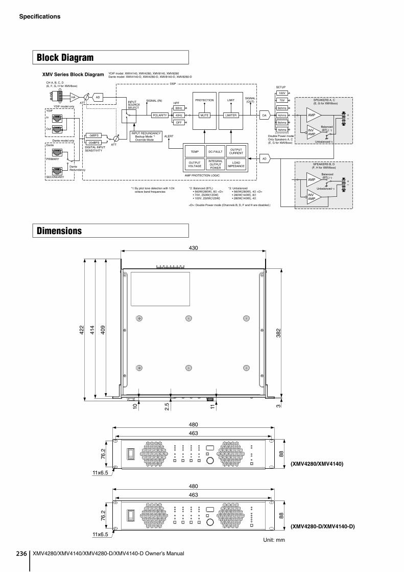
236
Specifications
XMV4280/XMV4140/XMV4280-D/XMV4140-D Owner’s Manual
Block Diagram
Dimensions
G
HA
Dante
PRIMARY
SECONDARY
YDIF
In
Out
Dante model only
YDIF model only
LIMITERMUTE
OFF
HPF
POLARITY
LIMITPROTECTION
AMP PROTECTION LOGIC
TEMP
DSP
XMV Series Block Diagram
SETUP
AMP
AD
70V
ALERT
-20dBFS
DIGITAL INPUT SENSITIVITY
Dante Redundancy
INPUT SOURCE SELECT
INPUT REDUNDANCYBackup Mode *1
Override Mode
Balanced *2
Unbalanced *3
Balanced *2
Unbalanced *3
YDIF model: XMV4140, XMV4280, XMV8140, XMV8280Dante model: XMV4140-D, XMV4280-D, XMV8140-D, XMV8280-D
CH A, B, C, D(E, F, G, H for XMV8xxx)
AD
ATT
ATT
-3dBFS
SIGNAL (IN)
80Hz
40Hz
DC-FAULT
SIGNAL(OUT)
DA
100V
8ohms
4ohms
8ohms
4ohms
Double Power mode:Only Speakers A, C (E, G for XMV8xxx)
SPEAKERS A, C(E, G for XMV8xxx)
(BTL)
SPEAKERS B, D(F, H for XMV8xxx)
(BTL)
*1: By pilot tone detection with 1/24 octave band frequencies
*2: Balanced (BTL)• 560W{280W}, 8Ω <D> • 70V, 250W{125W} • 100V, 250W{125W}
*3: Unbalanced• 560W{280W}, 4Ω <D>• 280W{140W}, 8Ω• 280W{140W}, 4Ω
<D>: Double Power mode (Channels B, D, F and H are disabled.)
OUTPUTCURRENT
LOADIMPEDANCE
OUTPUTVOLTAGE
INTEGRALOUTPUTPOWER
INVAMP
AMP
INVAMP
430
422
414
409
382
3112.5
10
480
8876.2
463
11x6.5
480
8876.2
463
11x6.5Unit: mm
(XMV4280/XMV4140)
(XMV4280-D/XMV4140-D)
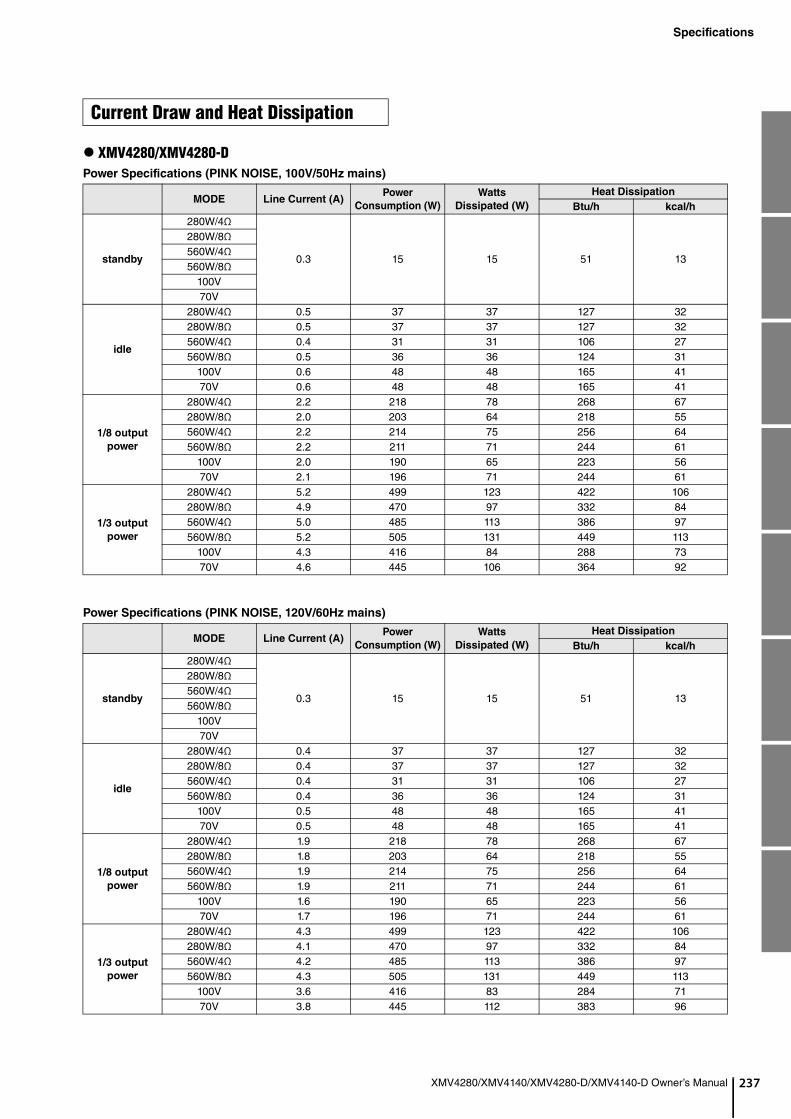
37
Specifications
XMV4280/XMV4140/XMV4280-D/XMV4140-D Owner’s Manual 2
XMV4280/XMV4280-DPower Specifications (PINK NOISE, 100V/50Hz mains)
Power Specifications (PINK NOISE, 120V/60Hz mains)
Current Draw and Heat Dissipation
MODE Line Current (A)Power
Consumption (W)
Watts
Dissipated (W)
Heat Dissipation
Btu/h kcal/h
standby
280W/4Ω
0.3 15 15 51 13
280W/8Ω560W/4Ω560W/8Ω
100V70V
idle
280W/4Ω 0.5 37 37 127 32280W/8Ω 0.5 37 37 127 32560W/4Ω 0.4 31 31 106 27560W/8Ω 0.5 36 36 124 31
100V 0.6 48 48 165 4170V 0.6 48 48 165 41
1/8 output
power
280W/4Ω 2.2 218 78 268 67280W/8Ω 2.0 203 64 218 55560W/4Ω 2.2 214 75 256 64560W/8Ω 2.2 211 71 244 61
100V 2.0 190 65 223 5670V 2.1 196 71 244 61
1/3 output
power
280W/4Ω 5.2 499 123 422 106280W/8Ω 4.9 470 97 332 84560W/4Ω 5.0 485 113 386 97560W/8Ω 5.2 505 131 449 113
100V 4.3 416 84 288 7370V 4.6 445 106 364 92
MODE Line Current (A)Power
Consumption (W)
Watts
Dissipated (W)
Heat Dissipation
Btu/h kcal/h
standby
280W/4Ω
0.3 15 15 51 13
280W/8Ω560W/4Ω560W/8Ω
100V70V
idle
280W/4Ω 0.4 37 37 127 32280W/8Ω 0.4 37 37 127 32560W/4Ω 0.4 31 31 106 27560W/8Ω 0.4 36 36 124 31
100V 0.5 48 48 165 4170V 0.5 48 48 165 41
1/8 output
power
280W/4Ω 1.9 218 78 268 67280W/8Ω 1.8 203 64 218 55560W/4Ω 1.9 214 75 256 64560W/8Ω 1.9 211 71 244 61
100V 1.6 190 65 223 5670V 1.7 196 71 244 61
1/3 output
power
280W/4Ω 4.3 499 123 422 106280W/8Ω 4.1 470 97 332 84560W/4Ω 4.2 485 113 386 97560W/8Ω 4.3 505 131 449 113
100V 3.6 416 83 284 7170V 3.8 445 112 383 96

238
Specifications
XMV4280/XMV4140/XMV4280-D/XMV4140-D Owner’s Manual
Power Specifications (PINK NOISE, 230V/50Hz mains)
1/8 power is typical of program material with occasional clipping. Refer to these figures for most applications.1/3 power represents program material with extremely heavy clipping.Test signal: Pink Noise, bandwidth limited from 22Hz to 22kHzAll channels driven1W = 0.860kcal/h, 1BTU = 0.252kcalNote that Line Voltage [V] x Line Current [A] = [VA], not equals to [W].
XMV4140/XMV4140-DPower Specifications (PINK NOISE, 100V/50Hz mains)
MODE Line Current (A)Power
Consumption (W)
Watts
Dissipated (W)
Heat Dissipation
Btu/h kcal/h
standby
280W/4Ω
0.3 15 15 51 13
280W/8Ω560W/4Ω560W/8Ω
100V70V
idle
280W/4Ω 0.4 37 37 127 32280W/8Ω 0.4 37 37 127 32560W/4Ω 0.4 31 31 106 27560W/8Ω 0.4 36 36 124 31
100V 0.4 47 47 161 4170V 0.4 47 47 161 41
1/8 output
power
280W/4Ω 1.05 212 72 247 62280W/8Ω 1.05 208 69 235 59560W/4Ω 1.04 207 68 232 58560W/8Ω 1.04 210 70 240 60
100V 0.94 188 63 216 5470V 0.94 195 70 240 60
1/3 output
power
280W/4Ω 2.2 476 100 343 86280W/8Ω 2.1 450 77 263 66560W/4Ω 2.2 463 91 311 78560W/8Ω 2.3 479 105 360 91
100V 1.9 400 67 229 5870V 2.0 429 96 328 83
MODE Line Current (A)Power
Consumption (W)
Watts
Dissipated (W)
Heat Dissipation
Btu/h kcal/h
standby
140W/4Ω
0.3 15 15 51 13
140W/8Ω280W/4Ω280W/8Ω
100V70V
idle
140W/4Ω 0.5 37 37 127 32140W/8Ω 0.5 37 37 127 32280W/4Ω 0.4 31 31 106 27280W/8Ω 0.5 36 36 124 31
100V 0.6 48 48 165 4170V 0.6 48 48 165 41
1/8 output
power
140W/4Ω 1.4 130 60 206 52140W/8Ω 1.3 125 55 189 48280W/4Ω 1.3 123 53 182 46280W/8Ω 1.4 130 60 206 52
100V 1.3 120 58 197 5070V 1.3 120 58 197 50
1/3 output
power
140W/4Ω 2.6 250 63 217 55140W/8Ω 2.5 240 53 183 46280W/4Ω 2.5 241 54 187 47280W/8Ω 2.6 250 63 217 55
100V 2.3 220 54 184 4670V 2.3 221 55 187 47

39
Specifications
XMV4280/XMV4140/XMV4280-D/XMV4140-D Owner’s Manual 2
Power Specifications (PINK NOISE, 120V/60Hz mains)
Power Specifications (PINK NOISE, 230V/50Hz mains)
1/8 power is typical of program material with occasional clipping. Refer to these figures for most applications.1/3 power represents program material with extremely heavy clipping.Test signal: Pink Noise, bandwidth limited from 22Hz to 22kHzAll channels driven1W = 0.860kcal/h, 1BTU = 0.252kcalNote that Line Voltage [V] x Line Current [A] = [VA], not equals to [W].
MODE Line Current (A)Power
Consumption (W)
Watts
Dissipated (W)
Heat Dissipation
Btu/h kcal/h
standby
140W/4Ω
0.3 15 15 51 13
140W/8Ω280W/4Ω280W/8Ω
100V70V
idle
140W/4Ω 0.4 37 37 127 32140W/8Ω 0.4 37 37 127 32280W/4Ω 0.3 31 31 106 27280W/8Ω 0.4 36 36 124 31
100V 0.5 48 48 165 4170V 0.5 48 48 165 41
1/8 output
power
140W/4Ω 1.2 130 60 206 52140W/8Ω 1.1 125 55 189 48280W/4Ω 1.1 123 53 182 46280W/8Ω 1.2 130 60 206 52
100V 1.0 120 58 197 5070V 1.1 120 58 197 50
1/3 output
power
140W/4Ω 2.2 250 63 217 55140W/8Ω 2.1 240 53 183 46280W/4Ω 2.1 241 54 187 47280W/8Ω 2.2 250 63 217 55
100V 1.9 220 54 184 4670V 1.9 221 55 187 47
MODE Line Current (A)Power
Consumption (W)
Watts
Dissipated (W)
Heat Dissipation
Btu/h kcal/h
standby
140W/4Ω
0.3 15 15 51 13
140W/8Ω280W/4Ω280W/8Ω
100V70V
idle
140W/4Ω 0.4 37 37 127 32140W/8Ω 0.4 37 37 127 32280W/4Ω 0.4 31 31 106 27280W/8Ω 0.4 36 36 124 31
100V 0.4 47 47 161 4170V 0.4 47 47 161 41
1/8 output
power
140W/4Ω 0.73 128 58 199 50140W/8Ω 0.73 127 57 196 49280W/4Ω 0.70 122 52 178 45280W/8Ω 0.73 128 58 199 50
100V 0.68 117 55 188 4770V 0.68 117 55 188 47
1/3 output
power
140W/4Ω 1.2 242 55 190 48140W/8Ω 1.1 233 46 159 40280W/4Ω 1.1 234 47 163 41280W/8Ω 1.2 243 56 193 49
100V 1.1 213 47 160 4070V 1.1 215 49 167 42
240
XMV4280/XMV4140/XMV4280-D/XMV4140-D Owner’s Manual(weee_eu_en_02)
(weee_eu_de_02)
(weee_eu_fr_02)
Information for users on collection and disposal of old equipment:
This symbol on the products, packaging, and/or accompanying documents means that used electrical and electronic products should not be mixed with general household waste.For proper treatment, recovery and recycling of old products, please take them to applicable collection points, in accor-dance with your national legislation.
By disposing of these products correctly, you will help to save valuable resources and prevent any potential negative effects on human health and the environment which could otherwise arise from inappropriate waste handling.
For more information about collection and recycling of old products, please contact your local municipality, your waste disposal service or the point of sale where you purchased the items.
For business users in the European Union:
If you wish to discard electrical and electronic equipment, please contact your dealer or supplier for further information.
Information on Disposal in other Countries outside the European Union:
This symbol is only valid in the European Union. If you wish to discard these items, please contact your local authorities or dealer and ask for the correct method of disposal.
Verbraucherinformation zur Sammlung und Entsorgung alter Elektrogeräte
Befindet sich dieses Symbol auf den Produkten, der Verpackung und/oder beiliegenden Unterlagen, so sollten benutzte elektrische Geräte nicht mit dem normalen Haushaltsabfall entsorgt werden.In Übereinstimmung mit Ihren nationalen Bestimmungen bringen Sie alte Geräte bitte zur fachgerechten Entsorgung, Wiederaufbereitung und Wiederverwendung zu den entsprechenden Sammelstellen.
Durch die fachgerechte Entsorgung der Elektrogeräte helfen Sie, wertvolle Ressourcen zu schützen, und verhindern mögliche negative Auswirkungen auf die menschliche Gesundheit und die Umwelt, die andernfalls durch unsachge-rechte Müllentsorgung auftreten könnten.
Für weitere Informationen zum Sammeln und Wiederaufbereiten alter Elektrogeräte kontaktieren Sie bitte Ihre örtliche Stadt- oder Gemeindeverwaltung, Ihren Abfallentsorgungsdienst oder die Verkaufsstelle der Artikel.
Information für geschäftliche Anwender in der Europäischen Union:
Wenn Sie Elektrogeräte ausrangieren möchten, kontaktieren Sie bitte Ihren Händler oder Zulieferer für weitere Informa-tionen.
Entsorgungsinformation für Länder außerhalb der Europäischen Union:
Dieses Symbol gilt nur innerhalb der Europäischen Union. Wenn Sie solche Artikel ausrangieren möchten, kontaktie-ren Sie bitte Ihre örtlichen Behörden oder Ihren Händler und fragen Sie nach der sachgerechten Entsorgungsmethode.
Informations concernant la collecte et le traitement des déchets d’équipements électriques et électroniques
Le symbole sur les produits, l'emballage et/ou les documents joints signifie que les produits électriques ou électroni-ques usagés ne doivent pas être mélangés avec les déchets domestiques habituels.Pour un traitement, une récupération et un recyclage appropriés des déchets d’équipements électriques et électroniq-ues, veuillez les déposer aux points de collecte prévus à cet effet, conformément à la réglementation nationale.
En vous débarrassant correctement des déchets d’équipements électriques et électroniques, vous contribuerez à la sauvegarde de précieuses ressources et à la prévention de potentiels effets négatifs sur la santé humaine qui pour-raient advenir lors d'un traitement inapproprié des déchets.
Pour plus d'informations à propos de la collecte et du recyclage des déchets d’équipements électriques et électroniq-ues, veuillez contacter votre municipalité, votre service de traitement des déchets ou le point de vente où vous avez acheté les produits.
Pour les professionnels dans l'Union européenne :
Si vous souhaitez vous débarrasser des déchets d’équipements électriques et électroniques, veuillez contacter votre vendeur ou fournisseur pour plus d'informations.
Informations sur la mise au rebut dans d'autres pays en dehors de l'Union européenne :
Ce symbole est seulement valable dans l'Union européenne. Si vous souhaitez vous débarrasser de déchets d’équipe-ments électriques et électroniques, veuillez contacter les autorités locales ou votre fournisseur et demander la métho-de de traitement appropriée.
41
XMV4280/XMV4140/XMV4280-D/XMV4140-D Owner’s Manual 2(weee_eu_es_02)
(weee_eu_it_02)
(lithium disposal)
Información para usuarios sobre la recogida y eliminación de los equipos antiguos
Este símbolo en los productos, embalajes y documentos anexos significa que los productos eléctricos y electrónicos no deben mezclarse con los desperdicios domésticos normales.Para el tratamiento, recuperación y reciclaje apropiados de los productos antiguos, llévelos a puntos de reciclaje correspondientes, de acuerdo con la legislación nacional.
Al deshacerse de estos productos de forma correcta, ayudará a ahorrar recursos valiosos y a impedir los posibles efectos desfavorables en la salud humana y en el entorno que de otro modo se producirían si se trataran los desperdi-cios de modo inapropiado.
Para obtener más información acerca de la recogida y el reciclaje de los productos antiguos, póngase en contacto con las autoridades locales, con el servicio de eliminación de basuras o con el punto de venta donde adquirió los artículos.
Para los usuarios empresariales de la Unión Europea:
Si desea desechar equipos eléctricos y electrónicos, póngase en contacto con su vendedor o proveedor para obtener más información.
Información sobre la eliminación en otros países fuera de la Unión Europea:
Este símbolo solo es válido en la Unión Europea. Si desea desechar estos artículos, póngase en contacto con las autoridades locales o con el vendedor y pregúnteles el método correcto.
Informazioni per gli utenti sulla raccolta e lo smaltimento di vecchia attrezzatura
Questi simboli sui prodotti, sull'imballaggio e/o sui documenti che li accompagnano, indicano che i prodotti elettrici ed elettronici non devono essere mischiati con i rifiuti generici.Per il trattamento, il recupero e il riciclaggio appropriato di vecchi prodotti, si prega di portarli ai punti di raccolta desi-gnati, in accordo con la legislazione locale.
Smaltendo correttamente questi prodotti si potranno recuperare risorse preziose, oltre a prevenire potenziali effetti negativi sulla salute e l'ambiente che potrebbero sorgere a causa del trattamento improprio dei rifiuti.
Per ulteriori informazioni sulla raccolta e il riciclaggio di vecchi prodotti, si prega di contattare l’amministrazione comu-nale locale, il servizio di smaltimento dei rifiuti o il punto vendita dove sono stati acquistati gli articoli.
Per utenti imprenditori dell'Unione europea:
Se si desidera scartare attrezzatura elettrica ed elettronica, si prega di contattare il proprio rivenditore o il proprio forni-tore per ulteriori informazioni.
Informazioni sullo smaltimento negli altri Paesi al di fuori dell'Unione europea:
Questi simboli sono validi solamente nell'Unione Europea; se si desidera scartare questi articoli, si prega di contattare le autorità locali o il rivenditore e richiedere informazioni sulla corretta modalità di smaltimento.
NEDERLAND / THE NETHERLANDS
• Dit apparaat bevat een lithium batterij voor geheugen back-up.• This apparatus contains a lithium battery for memory back-up.• Raadpleeg uw leverancier over de verwijdering van de batterij op het moment dat u het apparaat ann het einde van de levensduur of
gelieve dan contact op te nemen met de vertegenwoordiging van Yamaha in uw land.• For the removal of the battery at the moment of the disposal at the end of life please consult your retailer or Yamaha representative
office in your country.• Gooi de batterij niet weg, maar lever hem in als KCA.• Do not throw away the battery. Instead, hand it in as small chemical waste.

242
XMV4280/XMV4140/XMV4280-D/XMV4140-D Owner’s Manual
43
AD
anny
CAY1MT
U.SY6UT
MEYAInDT
BRYROT
ARYSOMBT
PAAMCA
YEMCT
THYSMT
GEYST
SWYSST
AUCZRO
YBST
POYSuT
MAOVT
PA5
XMV4280/XMV4140/XMV4280-D/XMV4140-D Owner’s Manual 2
DRESS LIST
Head Office/Manufacturer: Yamaha Corporation 10-1, Nakazawa-cho, Naka-ku, Hamamatsu, 430-8650, Jap(For European Countries) Importer: Yamaha Music Europe GmbH Siemensstrasse 22-34, 25462 Rellingen, Germa
NADAamaha Canada Music Ltd.35 Milner Avenue, Toronto, Ontario,1S 3R1, Canada
el: +1-416-298-1311
.A.amaha Corporation of America 600 Orangethorpe Avenue, Buena Park, CA 90620, .S.A.el: +1-714-522-9011
XICOamaha de México, S.A. de C.V.v. Insurgentes Sur 1647 Piso 9, Col. San José surgentes, Delegación Benito Juárez, México, .F., C.P. 03900, Méxicoel: +52-55-5804-0600
AZILamaha Musical do Brasil Ltda.ua Fidêncio Ramos, 302 – Cj 52 e 54 – Torre B – Vila límpia – CEP 04551-010 – São Paulo/SP, Brazilel: +55-11-3704-1377
GENTINAamaha Music Latin America, S.A.,ucursal Argentinalga Cossettini 1553, Piso 4 Norte,adero Este-C1107CEK,uenos Aires, Argentinael: +54-11-4119-7000
NAMA AND OTHER LATIN ERICAN COUNTRIES/RIBBEAN COUNTRIES
amaha Music Latin America, S.A.dif. Torre Banco General, Piso 7, Urbanización arbella, Calle 47 y Aquilino de la Guardia, iudad de Panamá, República de Panamáel: +507-269-5311
E UNITED KINGDOM/IRELANDamaha Music Europe GmbH (UK)herbourne Drive, Tilbrook, Milton Keynes, K7 8BL, U.K.
el: +44-1908-366700
RMANYamaha Music Europe GmbHiemensstrasse 22-34, 25462 Rellingen, Germanyel: +49-4101-303-0
ITZERLAND/LIECHTENSTEINamaha Music Europe GmbH, Branch witzerland in Thalwil eestrasse 18a, 8800 Thalwil, Switzerland el: +41-44-3878080
STRIA/BULGARIA/ECH REPUBLIC/HUNGARY/MANIA/SLOVAKIA/SLOVENIA
amaha Music Europe GmbHranch Austriachleiergasse 20, 1100 Wien, Austria el: +43-1-60203900
LANDamaha Music Europe GmbH p.z o.o. Oddział w Polscel. Wielicka 52, 02-657 Warszawa, Polandel: +48-22-880-08-88
LTAlimpus Music Ltd.alletta Road, Mosta MST9010, Maltael: +356-2133-2093
NETHERLANDS/BELGIUM/LUXEMBOURG
Yamaha Music Europe Branch BeneluxClarissenhof 5b, 4133 AB Vianen, The Netherlands Tel: +31-347-358040
FRANCEYamaha Music Europe 7 rue Ambroise Croizat, Zone d'activités de Pariest,77183 Croissy-Beaubourg, FranceTel: +33-1-6461-4000
ITALYYamaha Music Europe GmbH, Branch ItalyVia Tinelli N.67/69 20855 Gerno di Lesmo (MB), Italy Tel: +39-039-9065-1
SPAIN/PORTUGALYamaha Music Europe GmbH Ibérica, Sucursal en EspañaCtra. de la Coruña km. 17,200, 28231 Las Rozas de Madrid, SpainTel: +34-91-639-88-88
GREECEPhilippos Nakas S.A. The Music House19th klm. Leof. Lavriou 190 02 Peania – Attiki,GreeceTel: +30-210-6686168
SWEDEN/FINLAND/ICELANDYamaha Music Europe GmbH Germany filialScandinaviaJA Wettergrensgata 1, 400 43 Göteborg, SwedenTel: +46-31-89-34-00
DENMARKYamaha Music Denmark, Fillial of Yamaha Music Europe GmbH, TysklandGeneratorvej 8C, ST. TH. , 2860 Søborg, DenmarkTel: +45-44-92-49-00
NORWAYYamaha Music Europe GmbH Germany -Norwegian BranchGrini Næringspark 1, 1332 Østerås, Norway Tel: +47-6716-7800
CYPRUSYamaha Music Europe GmbHSiemensstrasse 22-34, 25462 Rellingen, GermanyTel: +49-4101-303-0
RUSSIAYamaha Music (Russia) LLC.Room 37, entrance 7, bld. 7, Kievskaya street, Moscow, 121059, RussiaTel: +7-495-626-5005
OTHER EUROPEAN COUNTRIESYamaha Music Europe GmbHSiemensstrasse 22-34, 25462 Rellingen, GermanyTel: +49-4101-3030
Yamaha Music Gulf FZEJAFZA-16, Office 512, P.O.Box 17328, Jebel Ali FZE, Dubai, UAETel: +971-4-801-1500
TURKEYYamaha Music Europe GmbHMerkezi Almanya Türkiye İstanbul ŞubesiMaslak Meydan Sodak, Spring Giz Plaza Bagimsiz Böl. No:3, Sariyer Istanbul, TurkeyTel: +90-212-999-8010
OTHER COUNTRIESYamaha Music Gulf FZEJAFZA-16, Office 512, P.O.Box 17328, Jebel Ali FZE, Dubai, UAETel: +971-4-801-1500
THE PEOPLE’S REPUBLIC OF CHINAYamaha Music & Electronics (China) Co.,Ltd.2F, Yunhedasha, 1818 Xinzha-lu, Jingan-qu, Shanghai, ChinaTel: +86-400-051-7700
INDIAYamaha Music India Private LimitedP-401, JMD Megapolis, Sector-48, Sohna Road, Gurgaon-122018, Haryana, IndiaTel: +91-124-485-3300
INDONESIAPT. Yamaha Musik Indonesia (Distributor) Yamaha Music Center Bldg. Jalan Jend. Gatot Subroto Kav. 4, Jakarta 12930, IndonesiaTel: +62-21-520-2577
KOREAYamaha Music Korea Ltd.8F, Dongsung Bldg. 21, Teheran-ro 87-gil, Gangnam-gu, Seoul, 06169, KoreaTel: +82-2-3467-3300
MALAYSIAYamaha Music (Malaysia) Sdn. Bhd.No.8, Jalan Perbandaran, Kelana Jaya, 47301 Petaling Jaya, Selangor, MalaysiaTel: +60-3-78030900
SINGAPOREYamaha Music (Asia) Private LimitedBlock 202 Hougang Street 21, #02-00,Singapore 530202, SingaporeTel: +65-6740-9200
TAIWANYamaha Music & Electronics Taiwan Co.,Ltd.2F., No.1, Yuandong Rd., Banqiao Dist.,New Taipei City 22063, Taiwan (R.O.C.)Tel: +886-2-7741-8888
THAILANDSiam Music Yamaha Co., Ltd.3, 4, 15, 16th Fl., Siam Motors Building, 891/1 Rama 1 Road, Wangmai, Pathumwan, Bangkok 10330, ThailandTel: +66-2215-2622
VIETNAMYamaha Music Vietnam Company Limited15th Floor, Nam A Bank Tower, 201-203 Cach Mang Thang Tam St., Ward 4, Dist.3,Ho Chi Minh City, VietnamTel: +84-8-3818-1122
OTHER ASIAN COUNTRIES http://asia.yamaha.com/
AUSTRALIAYamaha Music Australia Pty. Ltd.Level 1, 80 Market Street, South Melbourne, VIC 3205, AustraliaTel: +61-3-9693-5111
COUNTRIES AND TRUST TERRITORIES IN PACIFIC OCEAN
http://asia.yamaha.com/
NORTH AMERICA
CENTRAL & SOUTH AMERICA
EUROPE
AFRICA
MIDDLE EAST
ASIA
OCEANIA
0

Yamaha Pro Audio global websitehttp://www.yamaha.com/proaudio/
Yamaha Downloadshttp://download.yamaha.com/
ZZ42580
Manual Development Group© 2013 Yamaha Corporation
Published 12/2017 改版 POES-F0
厂名:雅马哈电子(苏州)有限公司
厂址:江苏省苏州市苏州新区鹿山路18号
雅马哈乐器音响(中国)投资有限公司上海市静安区新闸路1818号云和大厦2楼客户服务热线:4000517700公司网址:http://www.yamaha.com.cn