Embed Size (px)
Citation preview
February 2008 Rev 3 1/16
16
LM135-LM235-LM335
Precision temperature sensors
Features■ Directly calibrated in °K
■ 1°C initial accuracy
■ Operates from 450µA to 5mA
■ Less than 1Ω dynamic impedance
DescriptionThe LM135, LM235, LM335 are precision temperature sensors which can be easily calibrated. They operate as a 2-terminal Zener and the breakdown voltage is directly proportional to the absolute temperature at 10mV/°K.
The circuit has a dynamic impedance of less than 1Ω and operates within a range of current from 450µA to 5mA without alteration of its characteristics.
Calibrated at +25°C, the LM135, LM235, and LM335 have a typical error of less than 1°C over a 100°C temperature range. Unlike other sensors, the LM135, LM235, LM335 have a linear output.
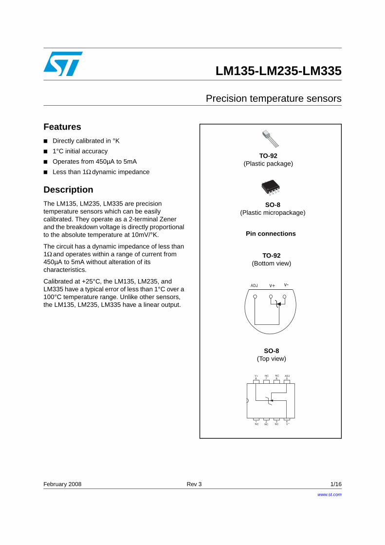
TO-92(Plastic package)
SO-8(Plastic micropackage)
TO-92(Bottom view)
SO-8(Top view)
Pin connections
ADJ v+ v-
8 7 6 5
1 2 3 4
V+ NC ADJ
NC NC VNC
NC
-
www.st.com
Schematic diagram LM135-LM235-LM335
2/16
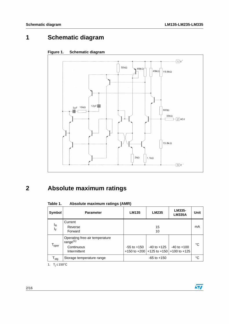
1 Schematic diagram
Figure 1. Schematic diagram
2 Absolute maximum ratings
Table 1. Absolute maximum ratings (AMR)
Symbol Parameter LM135 LM235LM335-LM335A
Unit
IRIF
CurrentReverseForward
1510
mA
Toper
Operating free-air temperature range(1)
ContinuousIntermittent
1. Tj ≤ 150°C
-55 to +150+150 to +200
-40 to +125+125 to +150
-40 to +100+100 to +125
°C
Tstg Storage temperature range -65 to +150 °C

LM135-LM235-LM335 Temperature accuracy
3/16
3 Temperature accuracy
4 Electrical characteristics
Note: Accuracy measurements are made in a well-stirred oil bath. For other conditions, self-heating must be considered
Table 2. Temperature accuracy
Parameter
LM135 - LM235 - LM335A
LM335Unit
Min. Typ. Max. Min. Typ. Max.
Operating output voltageTcase = +25°C, IR = 1mA 2.95 2.98 3.01 2.92 2.98 3.04 V
Uncalibrated temperature error (IR = 1mA)Tcase = +25°CTmin ≤ Tcase ≤ Tmax
12
35
45
69
°C
Temperature error with 25°C calibration
Tmin ≤ Tcase ≤ Tmax., IR = 1mA
LM135 - LM235LM335LM335A
0.5
0.5
1.5
11 2
°C
Calibrated error at extended temperature
Tcase = Tmax (intermittent) 2 2 °C
Non-linearity (IR = 1mA)
LM135 - LM235LM335LM335A
0.3
0.3
1
1.50.3 1.5
°C
Table 3. Electrical characteristics
ParameterLM135 - LM235 LM335-LM335A
UnitMin. Typ. Max. Min. Typ. Max.
Operating output voltage change with current450µA ≤ IR ≤ 5mA at constant temperature 2.5 10 3 14 mV
Dynamic impedance (IR = 1mA) 0.5 0.6 Ω
Output voltage temperature drift +10 +10 mV/°C
Time constantStill airAir 0.5m/sStirred oil
80101
80101
s
Time stability (Tcase = +125°C) 0.2 0.2 °C/kh
Electrical characteristics LM135-LM235-LM335
4/16
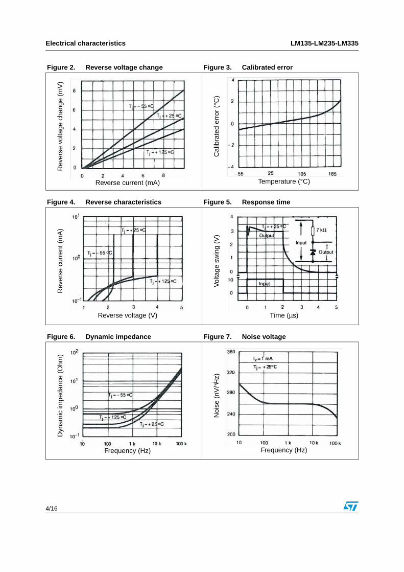
Figure 2. Reverse voltage change Figure 3. Calibrated error
Reverse current (mA)
Rev
erse
vol
tage
cha
nge
(mV
)
Temperature (°C)
Cal
ibra
ted
erro
r (°
C)
Figure 4. Reverse characteristics Figure 5. Response time
Rev
erse
cur
rent
(m
A)
Reverse voltage (V)
Vol
tage
sw
ing
(V)
Time (µs)
Figure 6. Dynamic impedance Figure 7. Noise voltage
Dyn
amic
impe
danc
e (O
hm)
Frequency (Hz)
Noi
se (
nV/√H
z)
Frequency (Hz)
LM135-LM235-LM335 Electrical characteristics
5/16
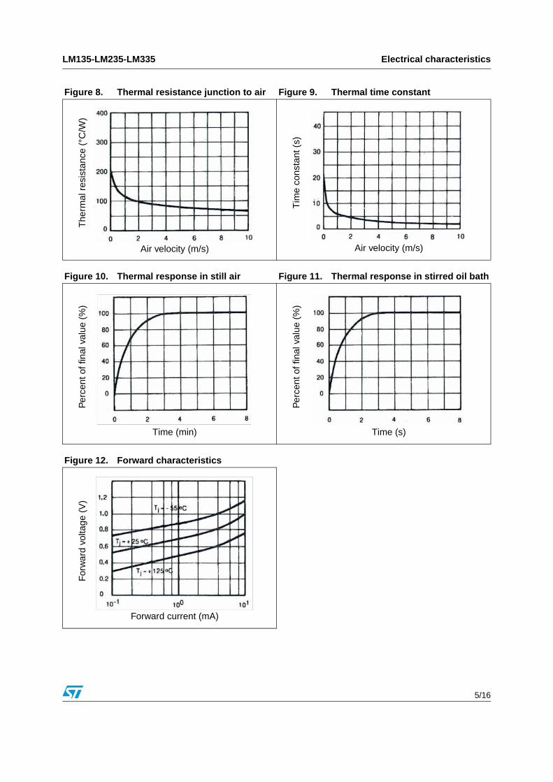
Figure 8. Thermal resistance junction to air Figure 9. Thermal time constantT
herm
al r
esis
tanc
e (°
C/W
)
Air velocity (m/s) Air velocity (m/s)
Tim
e co
nsta
nt (
s)
Figure 10. Thermal response in still air Figure 11. Thermal response in stirred oil bath
Figure 12. Forward characteristics
Per
cent
of f
inal
val
ue (
%)
Time (min)
Per
cent
of f
inal
val
ue (
%)
Time (s)
For
war
d vo
ltage
(V
)
Forward current (mA)
Application information LM135-LM235-LM335
6/16
5 Application information
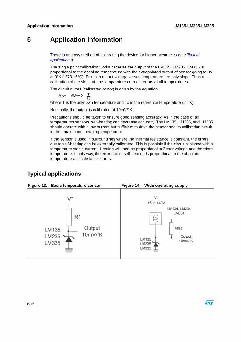
There is an easy method of calibrating the device for higher accuracies (see Typical applications).
The single point calibration works because the output of the LM135, LM235, LM335 is proportional to the absolute temperature with the extrapolated output of sensor going to 0V at 0°K (-273.15°C). Errors in output voltage versus temperature are only slope. Thus a calibration of the slope at one temperature corrects errors at all temperatures.
The circuit output (calibrated or not) is given by the equation:
VOT + VOTO x
where T is the unknown temperature and To is the reference temperature (in °K).
Nominally, the output is calibrated at 10mV/°K.
Precautions should be taken to ensure good sensing accuracy. As in the case of all temperatures sensors, self-heating can decrease accuracy. The LM135, LM235, and LM335 should operate with a low current but sufficient to drive the sensor and its calibration circuit to their maximum operating temperature.
If the sensor is used in surroundings where the thermal resistance is constant, the errors due to self-heating can be externally calibrated. This is possible if the circuit is biased with a temperature stable current. Heating will then be proportional to Zener voltage and therefore temperature. In this way, the error due to self-heating is proportional to the absolute temperature as scale factor errors.
Typical applications
TTo-------
Figure 13. Basic temperature sensor Figure 14. Wide operating supply
LM135-LM235-LM335 Application information
7/16
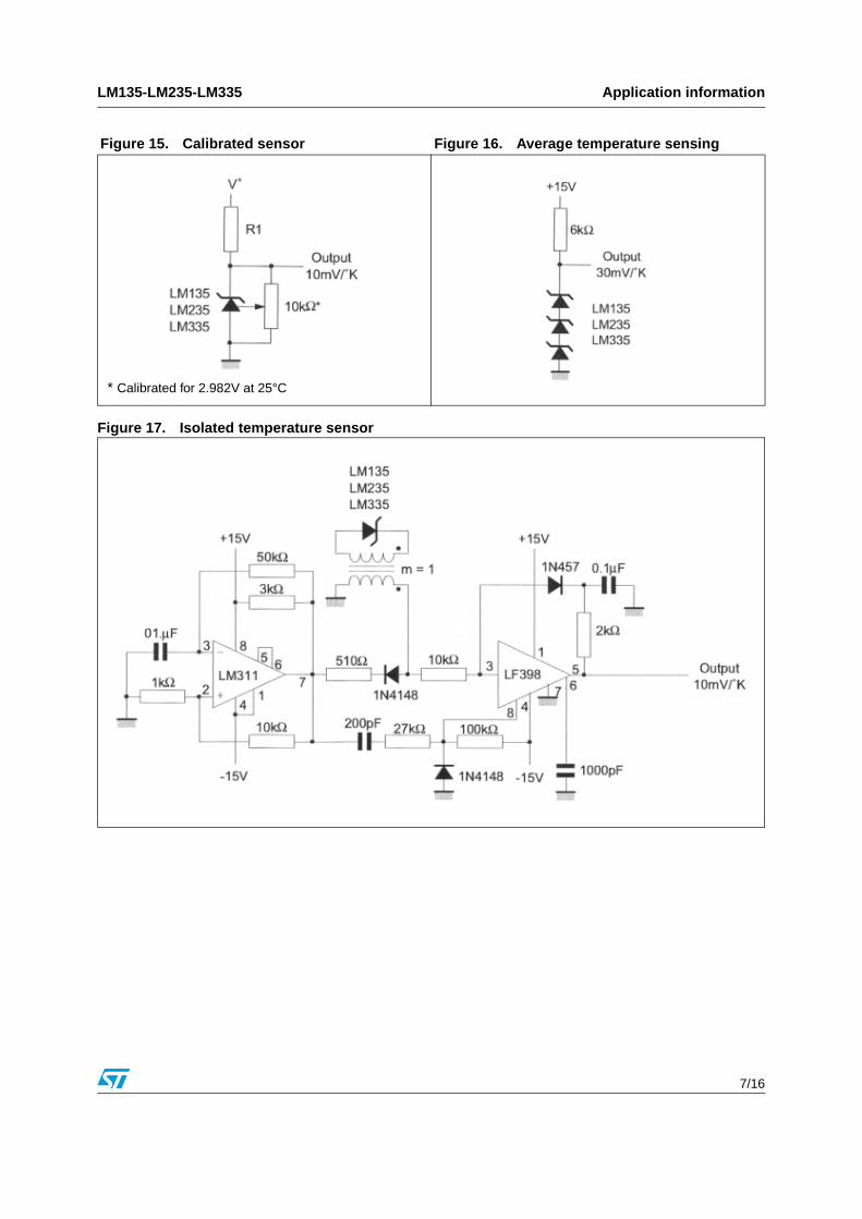
Figure 17. Isolated temperature sensor
Figure 15. Calibrated sensor Figure 16. Average temperature sensing
* Calibrated for 2.982V at 25°C
Application information LM135-LM235-LM335
8/16
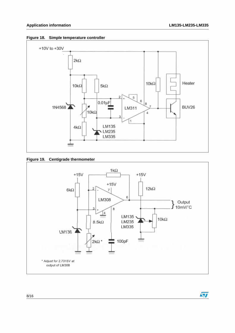
Figure 18. Simple temperature controller
Figure 19. Centigrade thermometer
LM135-LM235-LM335 Application information
9/16
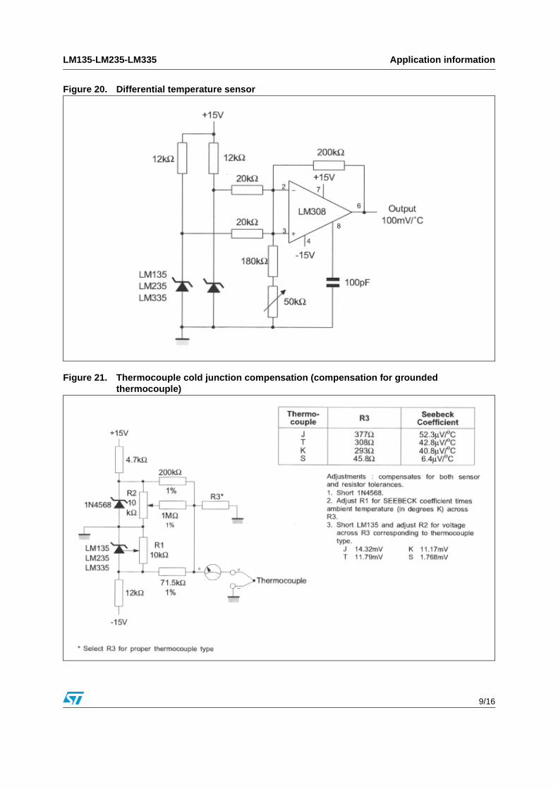
Figure 20. Differential temperature sensor
Figure 21. Thermocouple cold junction compensation (compensation for grounded thermocouple)
Application information LM135-LM235-LM335
10/16
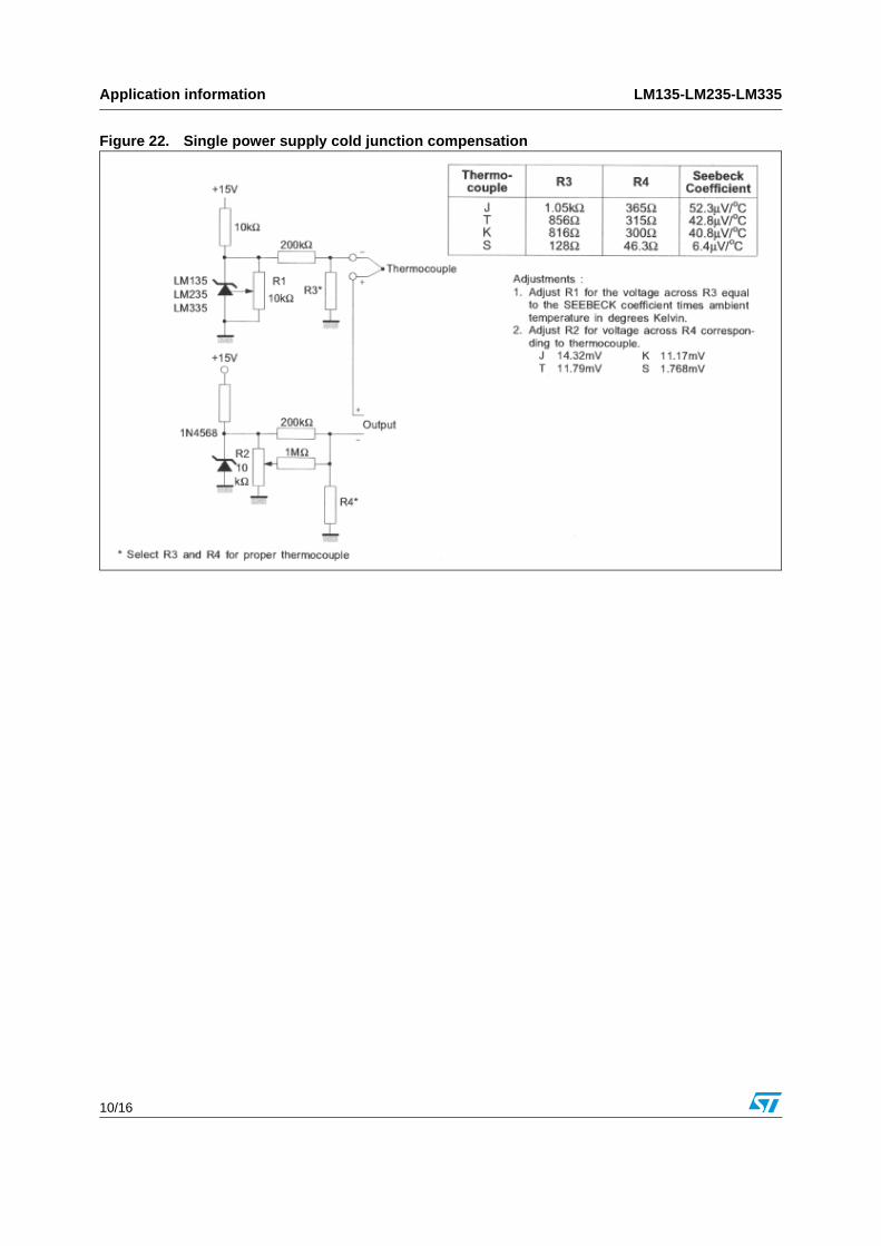
Figure 22. Single power supply cold junction compensation
LM135-LM235-LM335 Package information
11/16
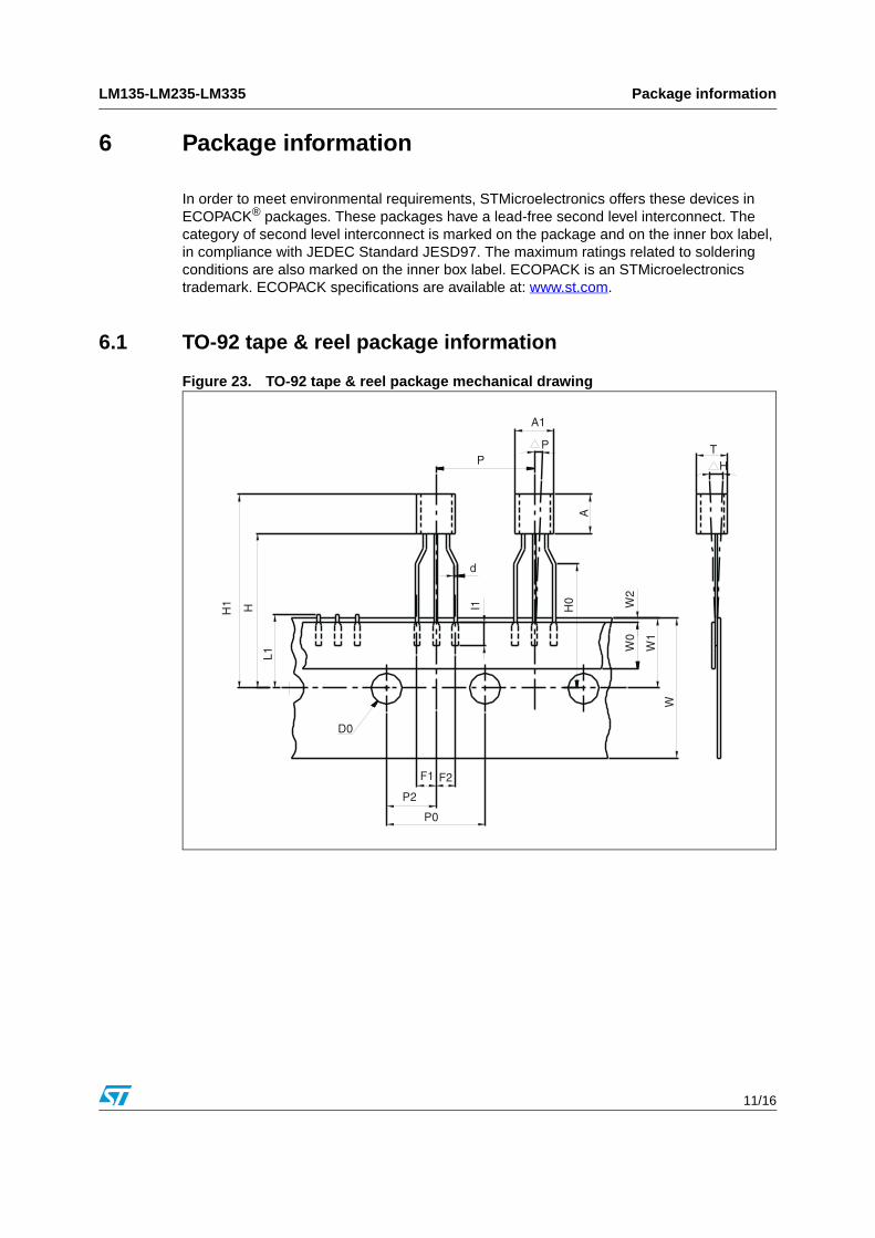
6 Package information
In order to meet environmental requirements, STMicroelectronics offers these devices in ECOPACK® packages. These packages have a lead-free second level interconnect. The category of second level interconnect is marked on the package and on the inner box label, in compliance with JEDEC Standard JESD97. The maximum ratings related to soldering conditions are also marked on the inner box label. ECOPACK is an STMicroelectronics trademark. ECOPACK specifications are available at: www.st.com.
6.1 TO-92 tape & reel package information
Figure 23. TO-92 tape & reel package mechanical drawing
A1
PP
A
TH
H1 H
L1
d
I1 H0 W
2W
0
W1
W
D0
F1 F2
P2
P0
Package information LM135-LM235-LM335
12/16
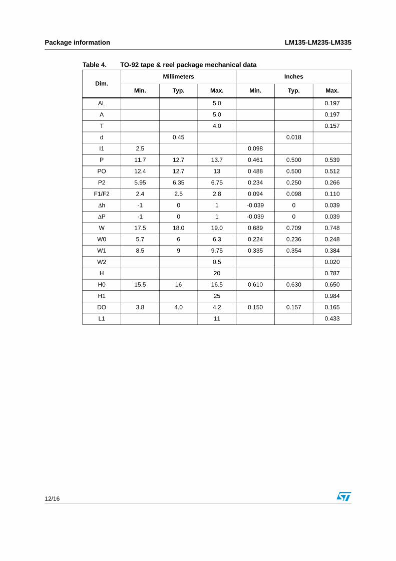
Table 4. TO-92 tape & reel package mechanical data
Dim.Millimeters Inches
Min. Typ. Max. Min. Typ. Max.
AL 5.0 0.197
A 5.0 0.197
T 4.0 0.157
d 0.45 0.018
I1 2.5 0.098
P 11.7 12.7 13.7 0.461 0.500 0.539
PO 12.4 12.7 13 0.488 0.500 0.512
P2 5.95 6.35 6.75 0.234 0.250 0.266
F1/F2 2.4 2.5 2.8 0.094 0.098 0.110
Δh -1 0 1 -0.039 0 0.039
ΔP -1 0 1 -0.039 0 0.039
W 17.5 18.0 19.0 0.689 0.709 0.748
W0 5.7 6 6.3 0.224 0.236 0.248
W1 8.5 9 9.75 0.335 0.354 0.384
W2 0.5 0.020
H 20 0.787
H0 15.5 16 16.5 0.610 0.630 0.650
H1 25 0.984
DO 3.8 4.0 4.2 0.150 0.157 0.165
L1 11 0.433
LM135-LM235-LM335 Package information
13/16
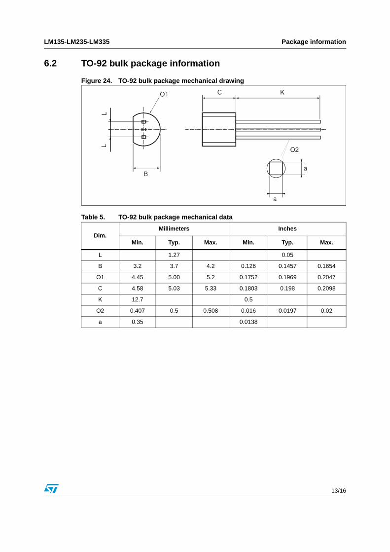
6.2 TO-92 bulk package information
Figure 24. TO-92 bulk package mechanical drawing
Table 5. TO-92 bulk package mechanical data
Dim.Millimeters Inches
Min. Typ. Max. Min. Typ. Max.
L 1.27 0.05
B 3.2 3.7 4.2 0.126 0.1457 0.1654
O1 4.45 5.00 5.2 0.1752 0.1969 0.2047
C 4.58 5.03 5.33 0.1803 0.198 0.2098
K 12.7 0.5
O2 0.407 0.5 0.508 0.016 0.0197 0.02
a 0.35 0.0138
Package information LM135-LM235-LM335
14/16
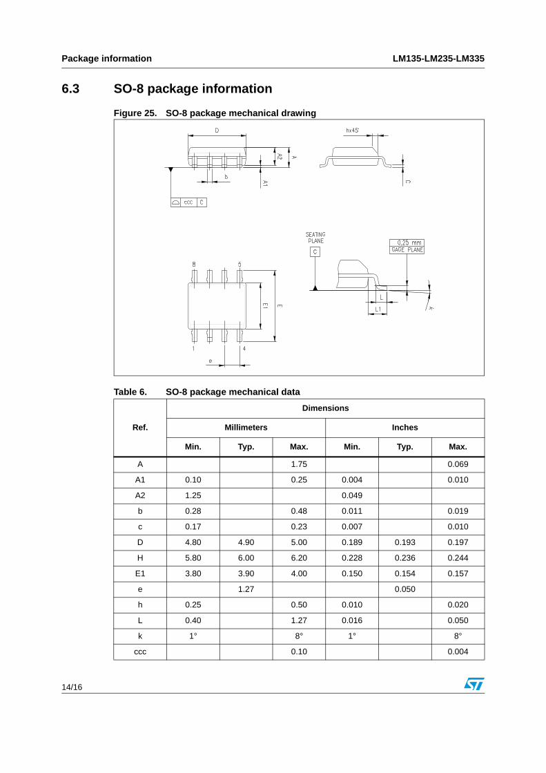
6.3 SO-8 package information
Figure 25. SO-8 package mechanical drawing
Table 6. SO-8 package mechanical data
Ref.
Dimensions
Millimeters Inches
Min. Typ. Max. Min. Typ. Max.
A 1.75 0.069
A1 0.10 0.25 0.004 0.010
A2 1.25 0.049
b 0.28 0.48 0.011 0.019
c 0.17 0.23 0.007 0.010
D 4.80 4.90 5.00 0.189 0.193 0.197
H 5.80 6.00 6.20 0.228 0.236 0.244
E1 3.80 3.90 4.00 0.150 0.154 0.157
e 1.27 0.050
h 0.25 0.50 0.010 0.020
L 0.40 1.27 0.016 0.050
k 1° 8° 1° 8°
ccc 0.10 0.004
LM135-LM235-LM335 Ordering information
15/16
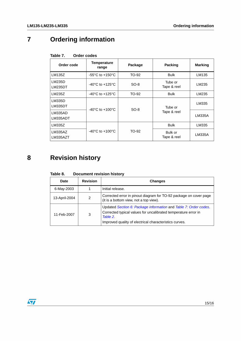
7 Ordering information
8 Revision history
Table 7. Order codes
Order codeTemperature
rangePackage Packing Marking
LM135Z -55°C to +150°C TO-92 Bulk LM135
LM235D
LM235DT-40°C to +125°C SO-8
Tube orTape & reel
LM235
LM235Z -40°C to +125°C TO-92 Bulk LM235
LM335D
LM335DT-40°C to +100°C SO-8
Tube orTape & reel
LM335
LM335AD
LM335ADTLM335A
LM335Z
-40°C to +100°C TO-92
Bulk LM335
LM335AZ
LM335AZTBulk or
Tape & reelLM335A
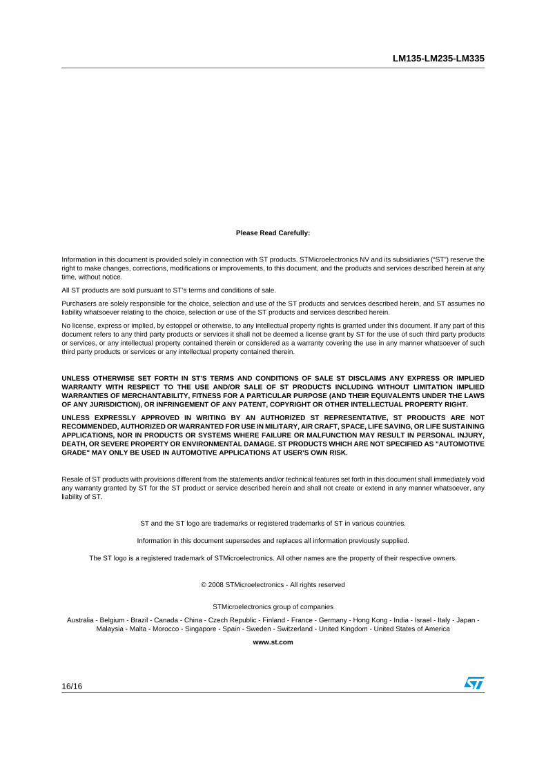
Table 8. Document revision history
Date Revision Changes
6-May-2003 1 Initial release.
13-April-2004 2Corrected error in pinout diagram for TO-92 package on cover page (it is a bottom view, not a top view).
11-Feb-2007 3
Updated Section 6: Package information and Table 7: Order codes.
Corrected typical values for uncalibrated temperature error in Table 2.
Improved quality of electrical characteristics curves.
LM135-LM235-LM335
16/16
Please Read Carefully:
Information in this document is provided solely in connection with ST products. STMicroelectronics NV and its subsidiaries (“ST”) reserve theright to make changes, corrections, modifications or improvements, to this document, and the products and services described herein at anytime, without notice.
All ST products are sold pursuant to ST’s terms and conditions of sale.
Purchasers are solely responsible for the choice, selection and use of the ST products and services described herein, and ST assumes noliability whatsoever relating to the choice, selection or use of the ST products and services described herein.
No license, express or implied, by estoppel or otherwise, to any intellectual property rights is granted under this document. If any part of thisdocument refers to any third party products or services it shall not be deemed a license grant by ST for the use of such third party productsor services, or any intellectual property contained therein or considered as a warranty covering the use in any manner whatsoever of suchthird party products or services or any intellectual property contained therein.
UNLESS OTHERWISE SET FORTH IN ST’S TERMS AND CONDITIONS OF SALE ST DISCLAIMS ANY EXPRESS OR IMPLIEDWARRANTY WITH RESPECT TO THE USE AND/OR SALE OF ST PRODUCTS INCLUDING WITHOUT LIMITATION IMPLIEDWARRANTIES OF MERCHANTABILITY, FITNESS FOR A PARTICULAR PURPOSE (AND THEIR EQUIVALENTS UNDER THE LAWSOF ANY JURISDICTION), OR INFRINGEMENT OF ANY PATENT, COPYRIGHT OR OTHER INTELLECTUAL PROPERTY RIGHT.
UNLESS EXPRESSLY APPROVED IN WRITING BY AN AUTHORIZED ST REPRESENTATIVE, ST PRODUCTS ARE NOTRECOMMENDED, AUTHORIZED OR WARRANTED FOR USE IN MILITARY, AIR CRAFT, SPACE, LIFE SAVING, OR LIFE SUSTAININGAPPLICATIONS, NOR IN PRODUCTS OR SYSTEMS WHERE FAILURE OR MALFUNCTION MAY RESULT IN PERSONAL INJURY,DEATH, OR SEVERE PROPERTY OR ENVIRONMENTAL DAMAGE. ST PRODUCTS WHICH ARE NOT SPECIFIED AS "AUTOMOTIVEGRADE" MAY ONLY BE USED IN AUTOMOTIVE APPLICATIONS AT USER’S OWN RISK.
Resale of ST products with provisions different from the statements and/or technical features set forth in this document shall immediately voidany warranty granted by ST for the ST product or service described herein and shall not create or extend in any manner whatsoever, anyliability of ST.
ST and the ST logo are trademarks or registered trademarks of ST in various countries.
Information in this document supersedes and replaces all information previously supplied.
The ST logo is a registered trademark of STMicroelectronics. All other names are the property of their respective owners.
© 2008 STMicroelectronics - All rights reserved
STMicroelectronics group of companies
Australia - Belgium - Brazil - Canada - China - Czech Republic - Finland - France - Germany - Hong Kong - India - Israel - Italy - Japan - Malaysia - Malta - Morocco - Singapore - Spain - Sweden - Switzerland - United Kingdom - United States of America
www.st.com


![High-precision sensors for Condition monitoring and …...High-precision sensors for Condition monitoring and Prevention of severe accident TF-Detector AWP-kit MF-Detector AD024_2[001-008].indd](https://img.pdfslide.tips/doc/110x75/5e9bbb58825ff2524a5cd5bb/high-precision-sensors-for-condition-monitoring-and-high-precision-sensors-for.jpg)