Embed Size (px)
Citation preview
Chapter Preparation• Students need to download and print the following documents
before class:
• UCD_1.pdf
• UCD_2.pdf
• UCD_3.pdf
2020 502052 - Chapter 4 1
https://www.duonghuuphuc.com/download/cs502052/ch04-docs.zip
Outline1. Data flow diagrams
2. Creating DFD
3. Data modeling using entity-relationship (ER) model
502052 - Chapter 4 22020
Introduction• A process model can be used to further clarify the requirements
definition and use cases
• A process model is a graphical way of representing how a business system should operate
• A process model can be used to document the as-is system or the to-be system, whether computerized or not
2020 502052 - Chapter 4 3
Introduction• Data flow diagramming (DFD) is a technique that diagrams the
business processes and the data that pass among them
• Logical process models describe processes without suggesting how they are conducted
• Physical process models provide information that is needed to build the system
2020 502052 - Chapter 4 4
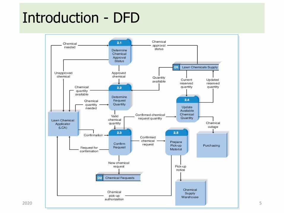
Introduction - DFD
2020 502052 - Chapter 4 5
Data Flow Diagrams
502052 - Chapter 4 62020
Elements of DFD• Process
• A process is an activity or a function performed for some specific business reason
• Data Flow
• A data flow is a single piece of data, or a logical collection of several pieces of information
2020 502052 - Chapter 4 7
Elements of DFD• Data Store
• A data store is a collection of data that is stored in some way
• External Entity
• An external entity is a person, organization, organization unit, or system that is external to the system, but interacts with it
2020 502052 - Chapter 4 8
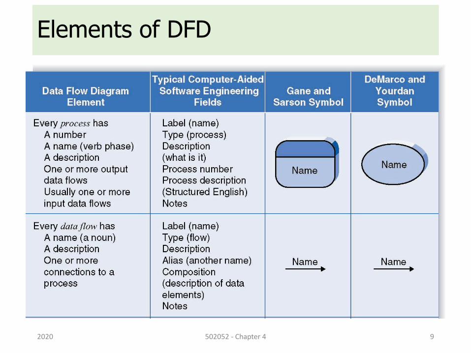
Elements of DFD
2020 502052 - Chapter 4 9
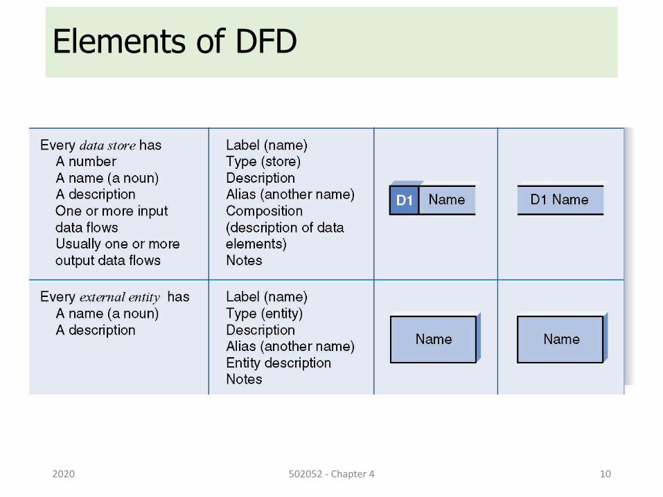
Elements of DFD
2020 502052 - Chapter 4 10
Using DFDs to Define Business Processes
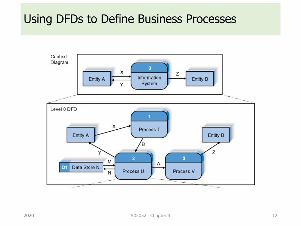
• Business processes are too complex to be explained in one DFD
• We should perform decomposition of the business process into a series of DFDs, each representing a lower level of detail
• Business process can be decomposed into 4 sub-diagrams:
• Context diagram
• Level-0 diagram
• Level-1 diagram
• Level-2 diagram
2020 502052 - Chapter 4 11
Using DFDs to Define Business Processes
2020 502052 - Chapter 4 12
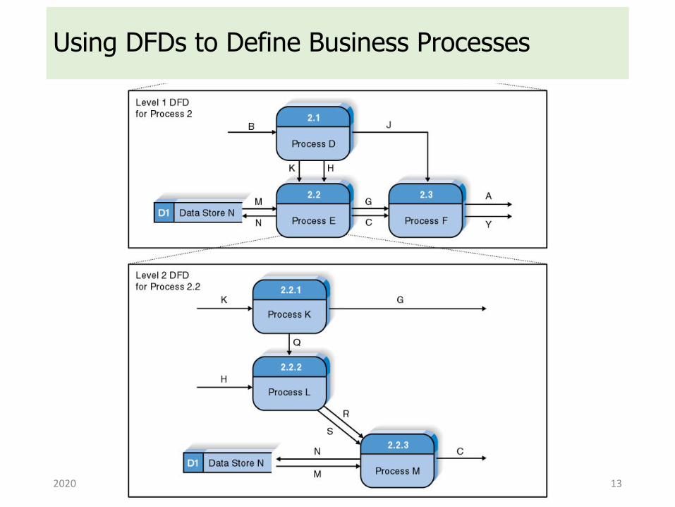
Using DFDs to Define Business Processes
2020 502052 - Chapter 4 13
Context Diagram• The first DFD in every business process is the context diagram
• It shows the entire system in context with its environment
• The context diagram
• shows the overall business process as just one process
• shows the data flows to and from external entities
2020 502052 - Chapter 4 14
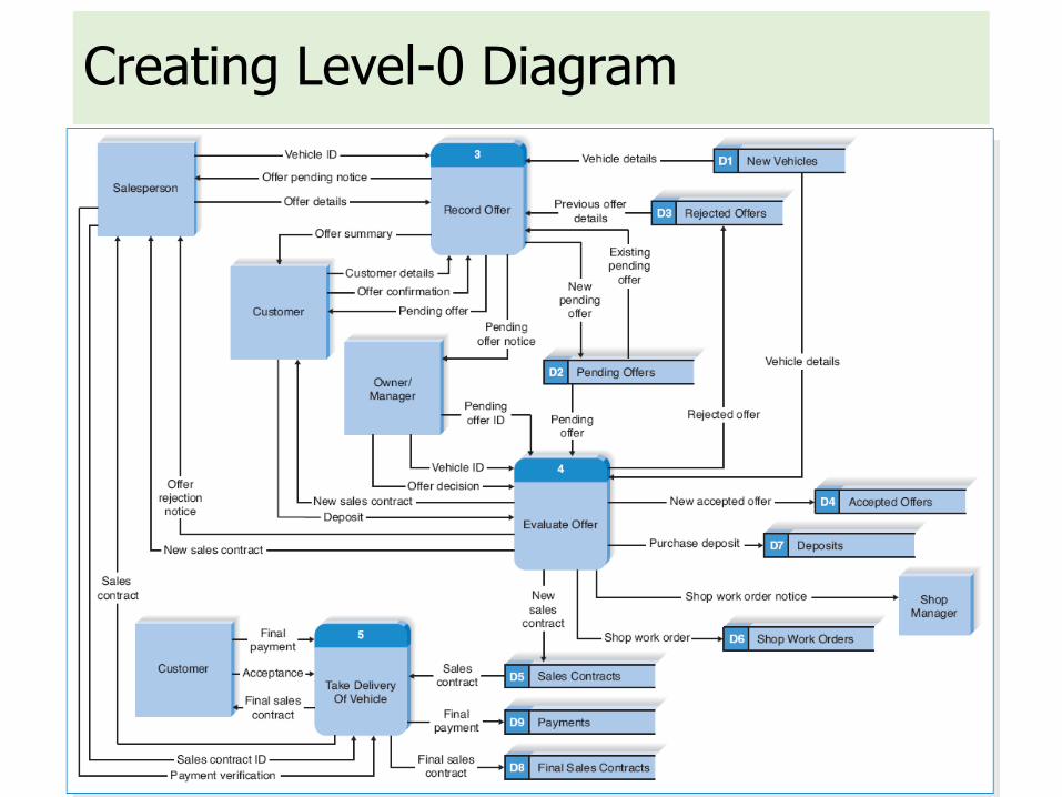
Level-0 Diagram• Level-0 DFD shows all the major high-level processes of the
system and how they are interrelated
• The Level-0 diagram shows all the processes at the first level the numbering, the data stores, external entities, and data flows among them
• A key concept: Balancing
• Ensuring that all information presented in a DFD at one level is accurately represented in the next-level DFD
• A process model has one and only one Level-0 DFD
2020 502052 - Chapter 4 15
Level-1 Diagram• Each process on the Level-0 DFD can be decomposed into a
more explicit DFD called Level-1 diagram
• The set of children and the parent are identical; they are simply different ways of looking at the same thing
• It is important to ensure that Level-0 and Level-1 DFDs are balanced
2020 502052 - Chapter 4 16
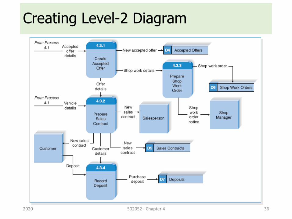
Level-2 Diagram• A Level-2 DFD shows all processes, data flows, and data stores
that comprise a single process on the Level-1 diagram
• It is important to ensure that Level-1 and Level-2 DFDs are balanced
2020 502052 - Chapter 4 17
Creating DFD
2020 502052 - Chapter 4 18
Steps to Create DFD• Build the context diagram
• Create DFD fragments for each use case
• Organize the DFD fragments into Level-0 diagram
• Develop Level-1 DFDs based on the steps with each use case
• In some cases, these Level-1 DFDs are further decomposed into Level-2 DFDs, Level-3 DFDs, …
• Validate the set of DFDs to make sure that they are complete and correct
2020 502052 - Chapter 4 19
Creating the Context Diagram• The context diagram defines how the business process or
computer system interacts with its environment
• Draw one process symbol for the business process or system being modeled (numbered 0 and named for the process or system)
• Add all inputs and outputs listed on the form of the use cases as data flows
• Draw in external entities as the source or destination of the data flows
• No data stores are included in the context diagram
2020 502052 - Chapter 4 22
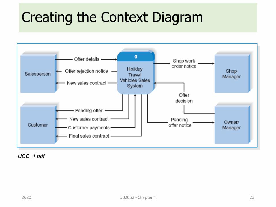
Creating the Context Diagram
2020 502052 - Chapter 4 23
UCD_1.pdf
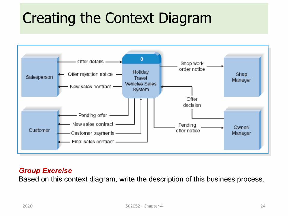
Creating the Context Diagram
2020 502052 - Chapter 4 24
Group ExerciseBased on this context diagram, write the description of this business process.
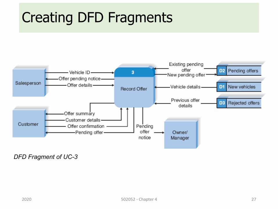
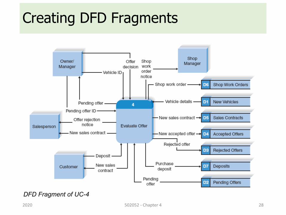
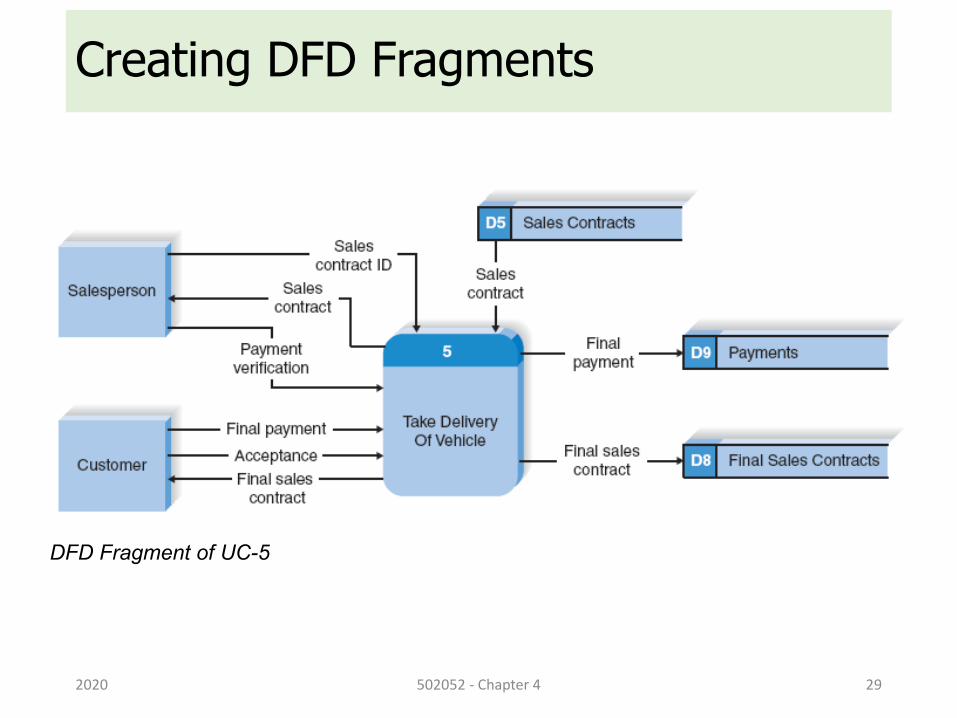
Creating DFD Fragments• This step is optional to convert context diagram to Level-0 DFD
• DFD fragments can then be combined to form Level-0 DFD
2020 502052 - Chapter 4 25
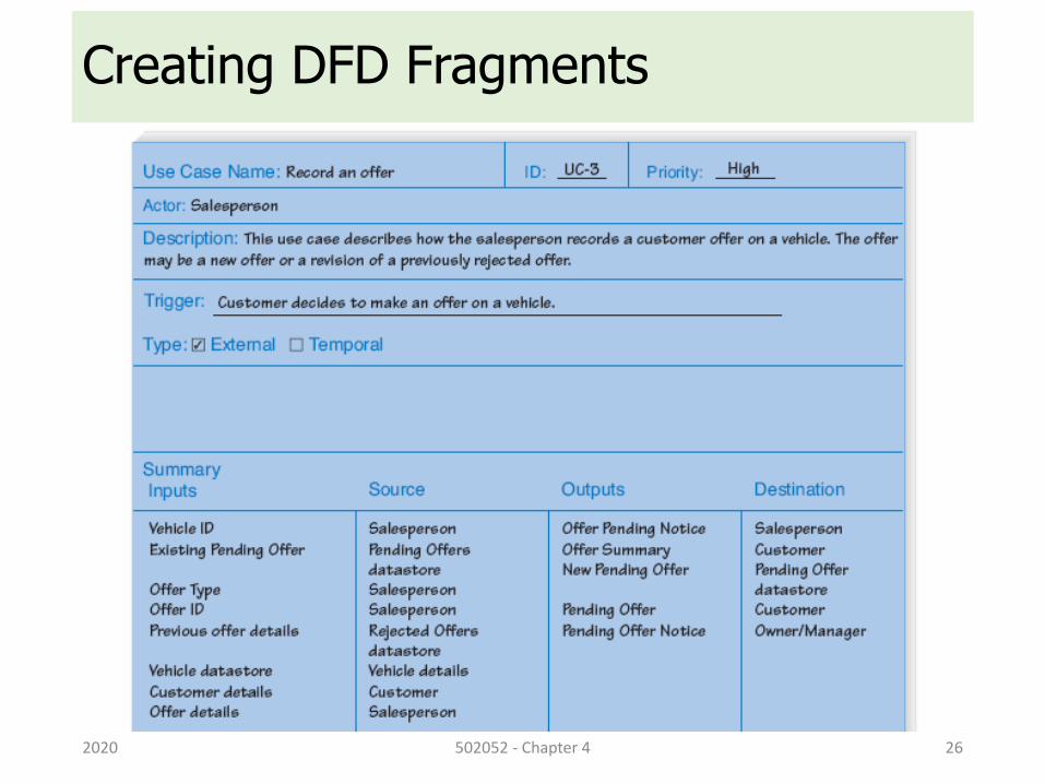
Creating DFD Fragments
2020 502052 - Chapter 4 26
Creating DFD Fragments
2020 502052 - Chapter 4 27
DFD Fragment of UC-3
Creating DFD Fragments
2020 502052 - Chapter 4 28
DFD Fragment of UC-4
Creating DFD Fragments
2020 502052 - Chapter 4 29
DFD Fragment of UC-5
Creating Level-0 Diagram• Combine the set of DFD fragments into one diagram - the Level-0
DFD
• There are not formal layout rules, but you should
• put the process that is first chronologically in the upper-left corner and work the way from top to bottom, left to right;
• reduce the number of crossed data flow lines.
• Iteration is the cornerstone of good DFD design
2020 502052 - Chapter 4 30
Creating Level-0 Diagram
2020 502052 - Chapter 4 31
Creating Level-1 Diagram
2020 502052 - Chapter 4 32
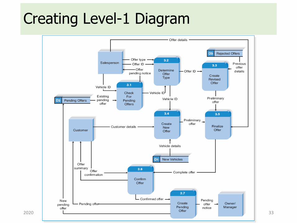
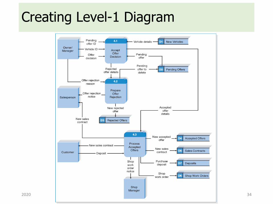
• Level-1 DFD – Lower-level DFDs for each process in the Level-0 DFD
• Each one of the use cases is turned into its own DFD
• Each major step in the use case becomes a process on the Level-1 DFD, with the inputs and outputs becoming the input and output data flows
• Level-1 DFDs include the sources and destinations of data flows for data stores and data flows to processes
• Including external entities in Level-1 and lower DFDs can simplify the readability of DFDs
Creating Level-1 Diagram
2020 502052 - Chapter 4 33
Creating Level-1 Diagram
2020 502052 - Chapter 4 34

Creating Level-1 Diagram
2020 502052 - Chapter 4 35
Creating Level-2 Diagram
2020 502052 - Chapter 4 36
Validating the DFD• Process
• Every process has a unique name that is an action-oriented verb phrase, a number, and a description
• Every process has at least one input data flow
• Every process has at least one output data flow
• Output data flows usually have different names than input data flows because the process changes the input into a different output in some way
• There are often between three and seven processes per DFD
2020 502052 - Chapter 4 37
Validating the DFD• Data Flow
• Every data flow has a unique name that is a noun, and a description
• Every data flow connects to at least one process
• Data flows only in one direction (no two-headed arrows)
• Minimize a number of data flow lines cross
2020 502052 - Chapter 4 38
Validating the DFD• Data Store
• Every data store has a unique name that is a noun, and a description
• Every data store has at least one input data flow (which means to add new data or change existing data in the data store) on some page of the DFD
• Every data store has at least one output data flow (which means to read data from the data store) on some page of the DFD
• You can represent an "Update" action by a bi-directional arrow
2020 502052 - Chapter 4 39
Validating the DFD• [External Entity]
• Every external entity has a unique name that is a noun, and a description
• Every external entity has at least one input or output data flow
2020 502052 - Chapter 4 40
Validating the DFD• Context diagram
• Every set of DFDs must have one context diagram
• Viewpoint
• There is a consistent viewpoint for the entire set of DFD
• Decomposition
• Every process is wholly and completely described by the processes on its children DFDs
• Balance
• Every data flow, data store, and external entity on a higher level DFD is shown on the lower-level DFD that decomposes it
2020 502052 - Chapter 4 41
Validating the DFD• Syntax errors
• They can be thought of as grammatical errors that violate the rules of the DFD language
• Semantics errors
• They can be thought of as misunderstandings by the analyst in collecting, analyzing, and reporting information about the system
• Syntax errors are easier to find and fix than are semantics errors
2020 502052 - Chapter 4 42
DFD – Exercises
2020 502052 - Chapter 4 43
Q.1 Creating DFD• Read the use-case descriptions in [UCD_2.pdf], and then create
the DFD (from context-level to Level-1).
2020 502052 - Chapter 4 44
Q.2 Creating DFD• Read the use-case descriptions in [UCD_3.pdf], and then create
the DFD (from context-level to Level-1).
2020 502052 - Chapter 4 45
Q.3 Creating DFD• Read the system descriptions in [SD_1.pdf], and then create the
DFD (from context-level to Level-1).
2020 502052 - Chapter 4 46
Data Modeling Using Entity-Relationship (ER) Model
2020 502052 - Chapter 4 52
Outline• ER Diagram
• Entity, Attribute and Relationship
• Refining the ER Design
• Relationship Degree Higher than Two
2020 502052 - Chapter 4 53
Data Modeling Using ER Model (1)• Entity-Relationship (ER) model
• Popular high-level conceptual data model
• ER diagrams
• Diagrammatic notation associated with the ER model
• Unified Modeling Language (UML)
2020 502052 - Chapter 4 54
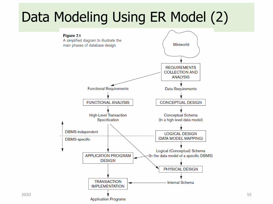
Data Modeling Using ER Model (2)
2020 502052 - Chapter 4 55
A Sample Database Application (1)• COMPANY
• Employees, departments, and projects
• Company is organized into departments
• Department controls a number of projects
• Employee: store each employee’s name, Social Security number, address, salary, sex (gender), and birth date
• Keep track of the dependents of each employee
2020 502052 - Chapter 4 58
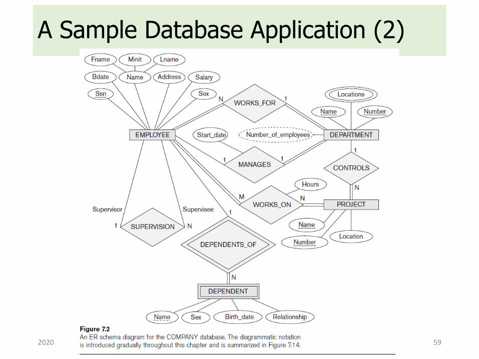
A Sample Database Application (2)
2020 502052 - Chapter 4 59
Outline1. ER Diagram
2. Entity, Attribute and Relationship
3. Refining the ER Design
4. Relationship Degree Higher than Two
2020 502052 - Chapter 4 60
Elements of ER Diagram• ER model describes data as:
• Entities
• Relationships
• Attributes
2020 502052 - Chapter 4 61
Entities and Attributes (1)• Entity
• Thing in real world with independent existence
• Attributes
• Particular properties that describe entity
• Types of attributes:
• Composite vs. simple (atomic) attributes
• Single-valued vs. multivalued attributes
• Stored vs. derived attributes
• NULL values
• Complex attributes
2020 502052 - Chapter 4 62
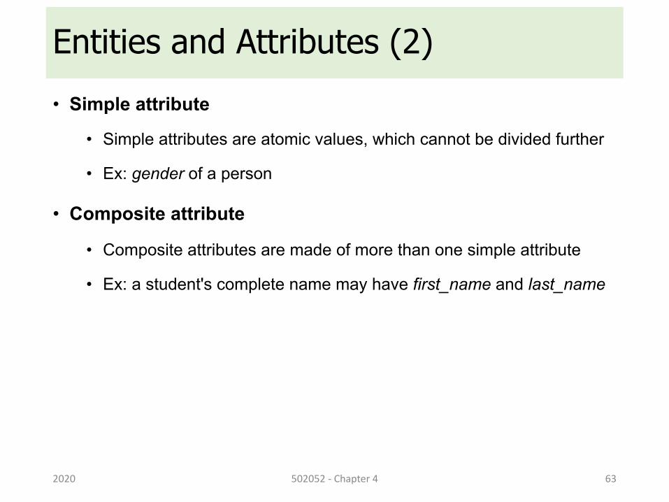
Entities and Attributes (2)• Simple attribute
• Simple attributes are atomic values, which cannot be divided further
• Ex: gender of a person
• Composite attribute
• Composite attributes are made of more than one simple attribute
• Ex: a student's complete name may have first_name and last_name
2020 502052 - Chapter 4 63
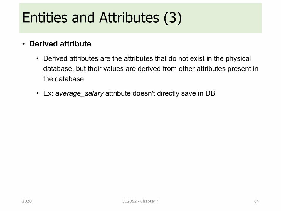
Entities and Attributes (3)• Derived attribute
• Derived attributes are the attributes that do not exist in the physical database, but their values are derived from other attributes present in the database
• Ex: average_salary attribute doesn't directly save in DB
2020 502052 - Chapter 4 64
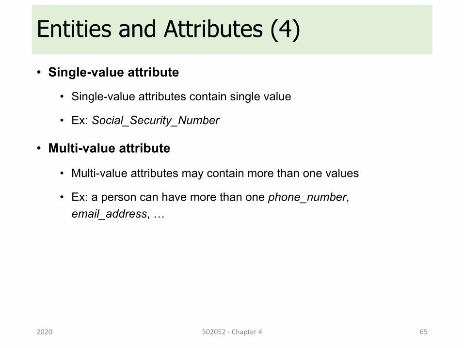
Entities and Attributes (4)• Single-value attribute
• Single-value attributes contain single value
• Ex: Social_Security_Number
• Multi-value attribute
• Multi-value attributes may contain more than one values
• Ex: a person can have more than one phone_number, email_address, …
2020 502052 - Chapter 4 65
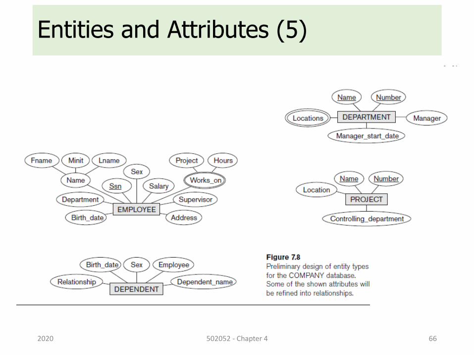
Entities and Attributes (5)
2020 502052 - Chapter 4 66
Entity-Set and Keys (1)• Key is an attribute or collection of attributes that uniquely identifies
an entity among entity set
• Example:
• studentID of a student makes him/her identifiable among students
• emailAddress of an user is also an unique identifier
2020 502052 - Chapter 4 67
Entity-Set and Keys (2)• Super Key
• A set of attributes (one or more) that collectively identifies an entity in an entity set
• Candidate Key
• A minimal super key is called a candidate key
• An entity set may have more than one candidate key
• Primary Key
• A primary key is one of the candidate keys chosen by the database designer to uniquely identify the entity set
2020 502052 - Chapter 4 68
Relationship (1)• Relationship
• When an attribute of one entity type refers to another entity type
• Represent references as relationships not attributes
• Example:
• An employee works_at a department
• A student enrolls in a course
• works_at and enrolls are called relationships
2020 502052 - Chapter 4 69
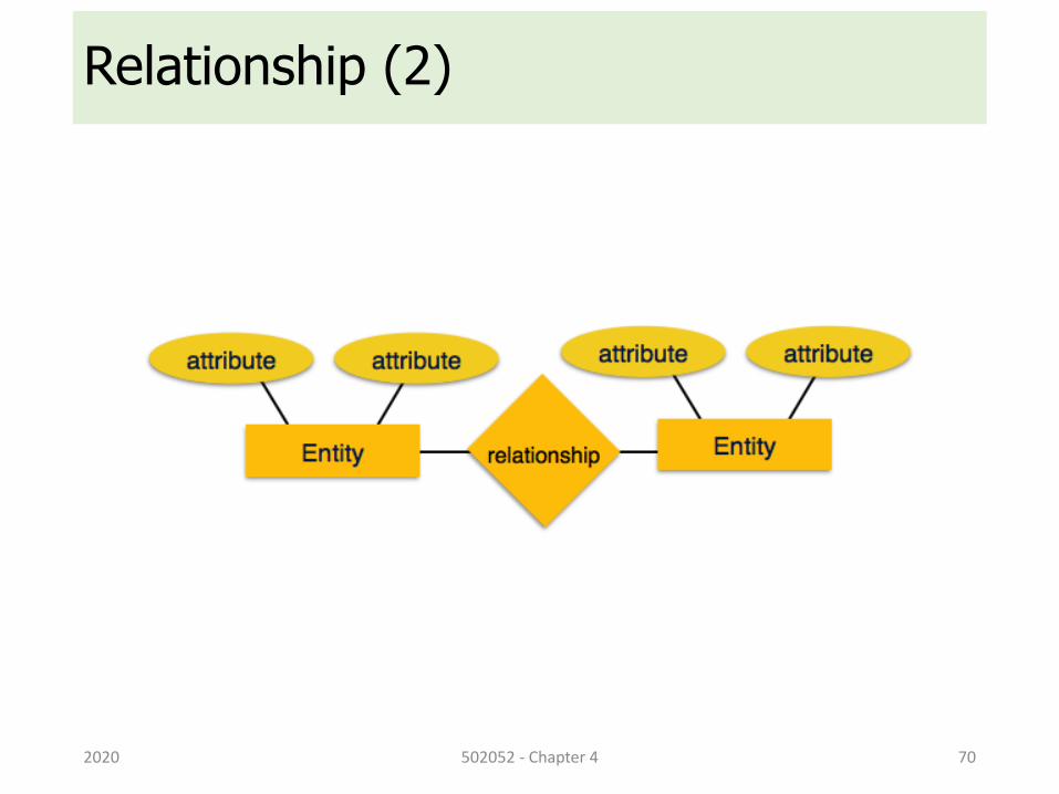
Relationship (2)
2020 502052 - Chapter 4 70
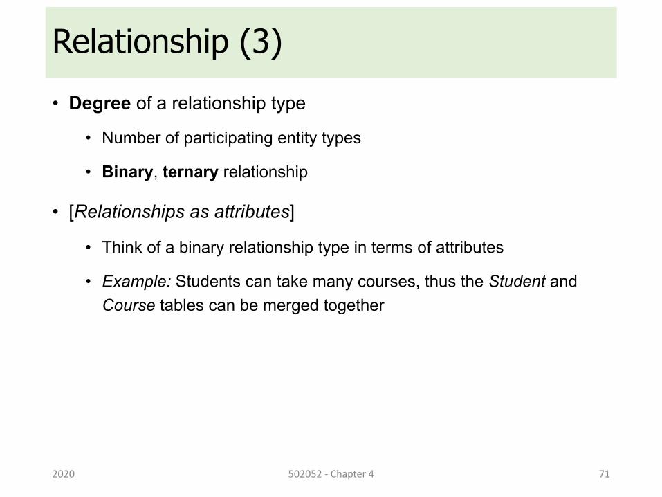
Relationship (3)• Degree of a relationship type
• Number of participating entity types
• Binary, ternary relationship
• [Relationships as attributes]
• Think of a binary relationship type in terms of attributes
• Example: Students can take many courses, thus the Student and Course tables can be merged together
2020 502052 - Chapter 4 71
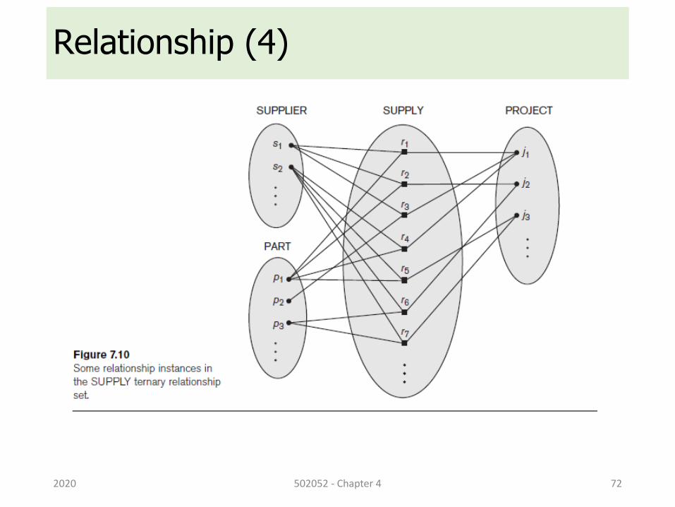
Relationship (4)
2020 502052 - Chapter 4 72
Role Names and Recursive Relationships
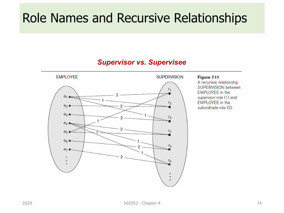
• Recursive relationships
• Same entity type participates more than once in a relationship type in different roles
• Must specify role name that signifies role that a participating entity plays in each relationship instance
2020 502052 - Chapter 4 73
Role Names and Recursive Relationships
2020 502052 - Chapter 4 74
Supervisor vs. Supervisee
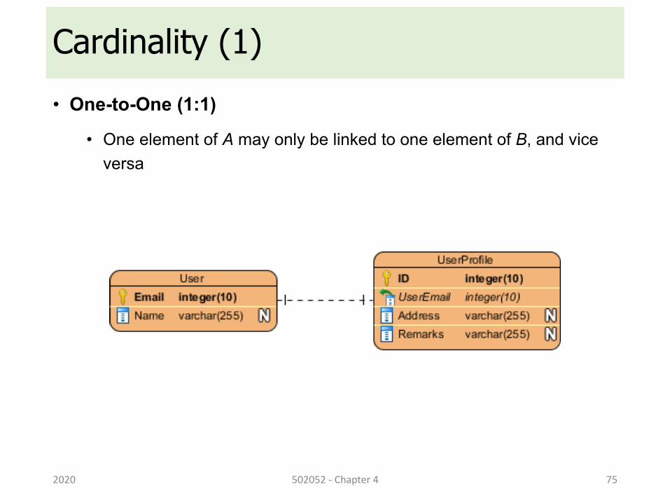
Cardinality (1)• One-to-One (1:1)
• One element of A may only be linked to one element of B, and vice versa
2020 502052 - Chapter 4 75
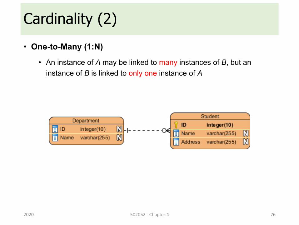
Cardinality (2)• One-to-Many (1:N)
• An instance of A may be linked to many instances of B, but an instance of B is linked to only one instance of A
2020 502052 - Chapter 4 76
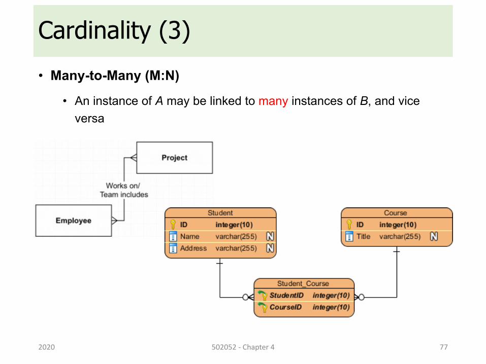
Cardinality (3)• Many-to-Many (M:N)
• An instance of A may be linked to many instances of B, and vice versa
2020 502052 - Chapter 4 77
Weak Entity Types (1)• Do not have key attributes of their own
• Identified by being related to specific entities from another entity type
• Identifying relationship
• Relates a weak entity type to its owner
• Always has a total participation constraint
2020 502052 - Chapter 4 79
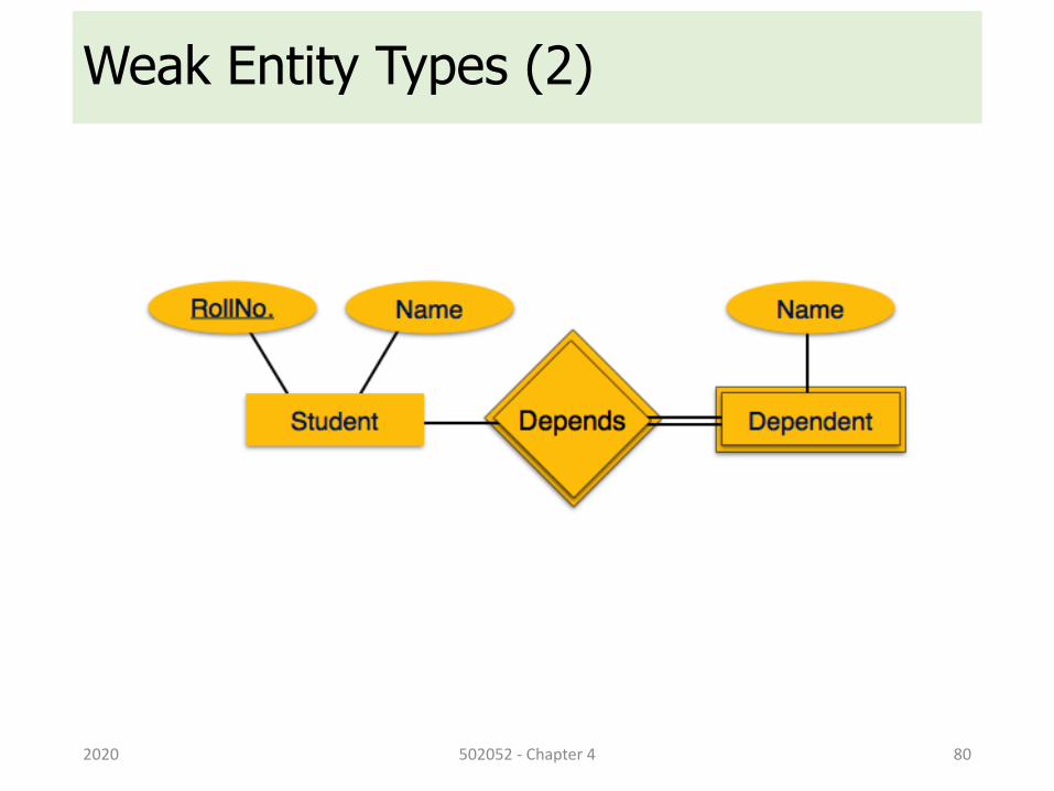
Weak Entity Types (2)
2020 502052 - Chapter 4 80
Outline1. ER Diagram
2. Entity, Attribute and Relationship
3. Refining the ER Design
4. Relationship Degree Higher than Two
2020 502052 - Chapter 4 81
Refining the ER Design• Change attributes that represent relationships into relationship
types
• Determine cardinality ratio and participation constraint of each relationship type
2020 502052 - Chapter 4 82
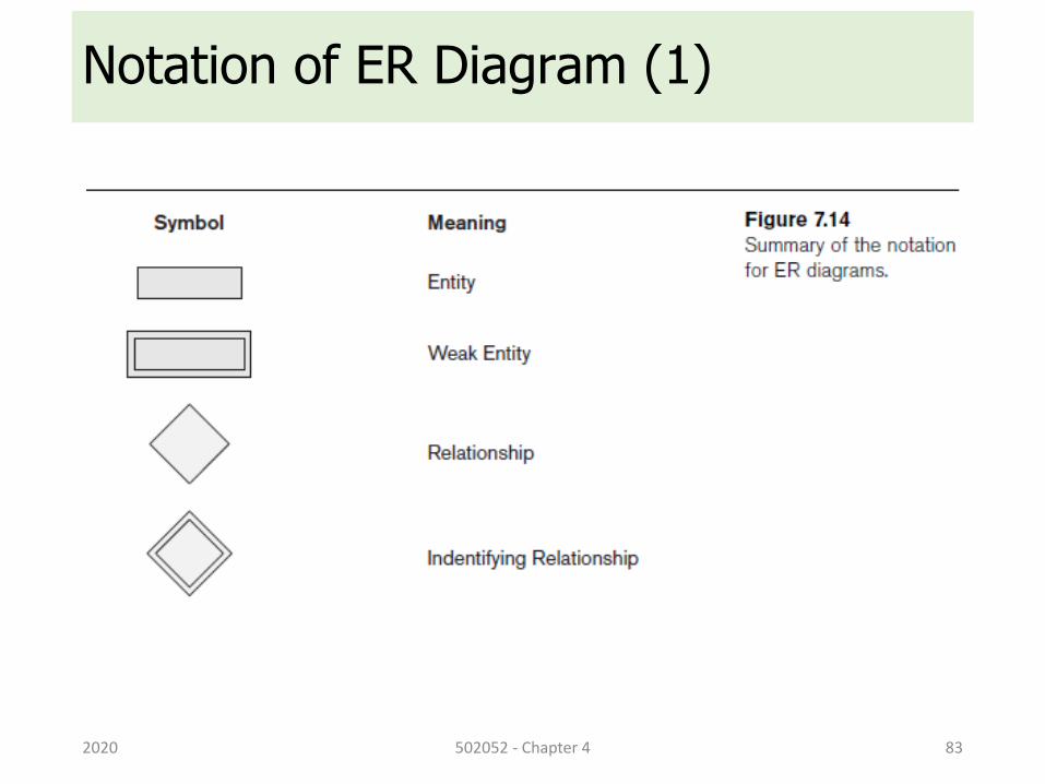
Notation of ER Diagram (1)
2020 502052 - Chapter 4 83
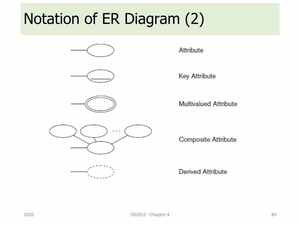
Notation of ER Diagram (2)
2020 502052 - Chapter 4 84
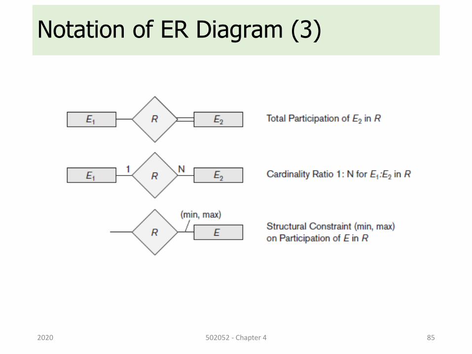
Notation of ER Diagram (3)
2020 502052 - Chapter 4 85
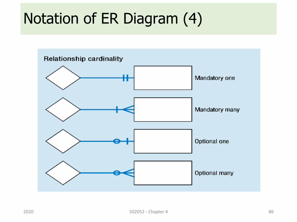
Notation of ER Diagram (4)
2020 502052 - Chapter 4 86
Proper Naming of Schema Constructs• Choose names that convey meanings attached to different
constructs in schema
• Nouns give rise to entity type names
• Verbs indicate names of relationship types
• Choose binary relationship names to make ER diagram readable from left to right and from top to bottom
2020 502052 - Chapter 4 87
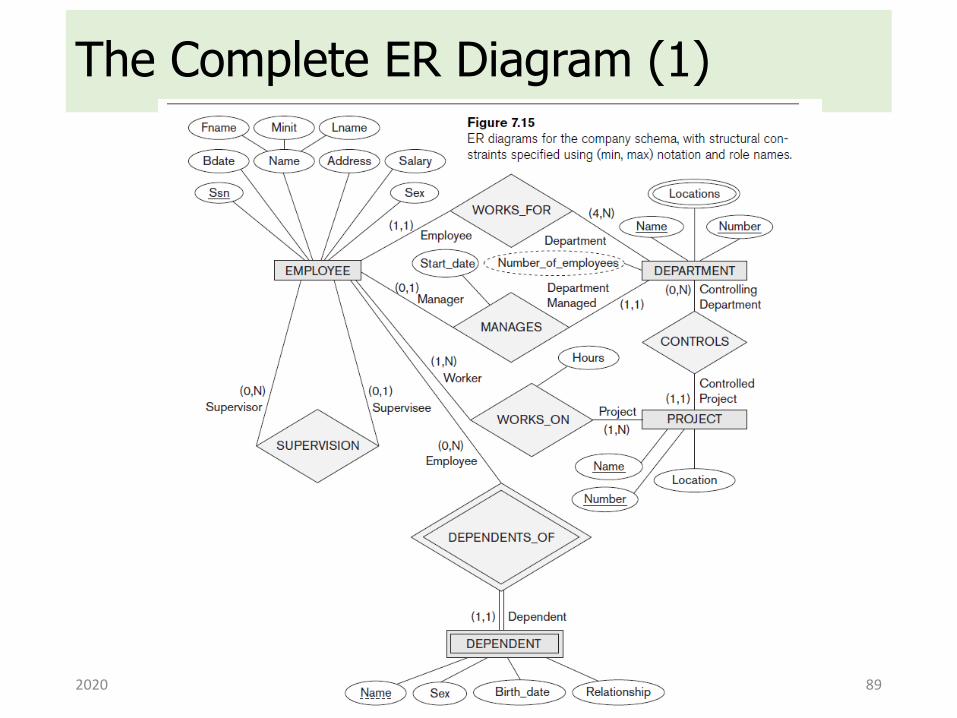
The Complete ER Diagram (1)
2020 502052 - Chapter 4 89
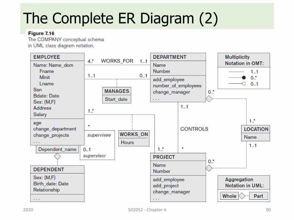
The Complete ER Diagram (2)
2020 502052 - Chapter 4 90
Outline1. ER Diagram
2. Entity, Attribute and Relationship
3. Refining the ER Design
4. Relationship Degree Higher than Two
2020 502052 - Chapter 4 91
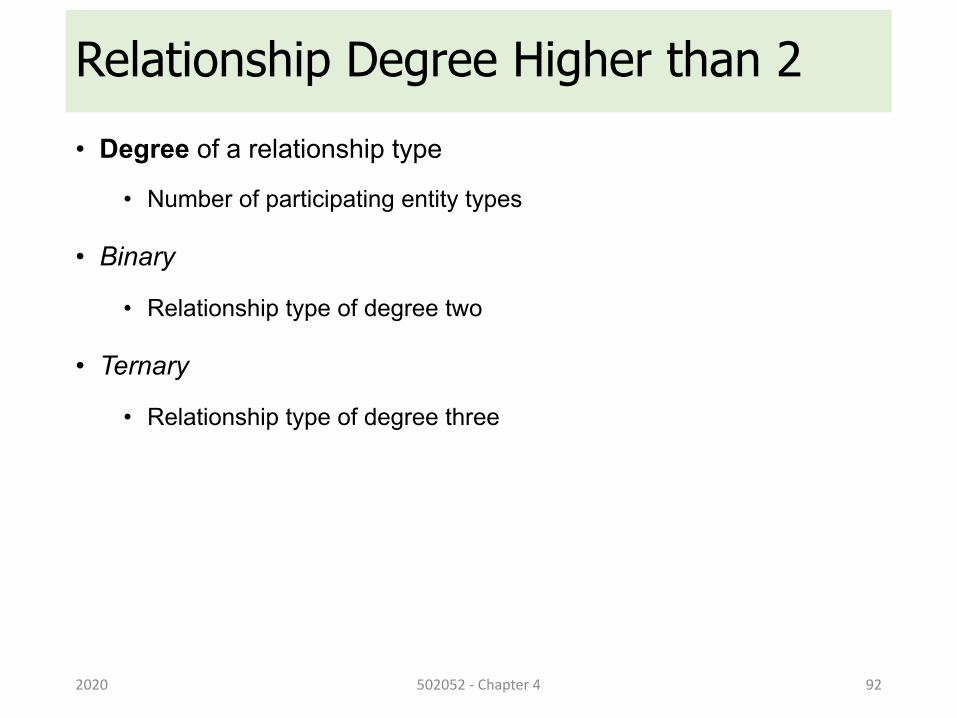
Relationship Degree Higher than 2• Degree of a relationship type
• Number of participating entity types
• Binary
• Relationship type of degree two
• Ternary
• Relationship type of degree three
2020 502052 - Chapter 4 92
Choosing between Binary and Ternary• Some database design tools permit only binary relationships
• Ternary relationship must be represented as a weak entity type
• No partial key and three identifying relationships
• Represent ternary relationship as a regular entity type
• By introducing an artificial or surrogate key
2020 502052 - Chapter 4 93
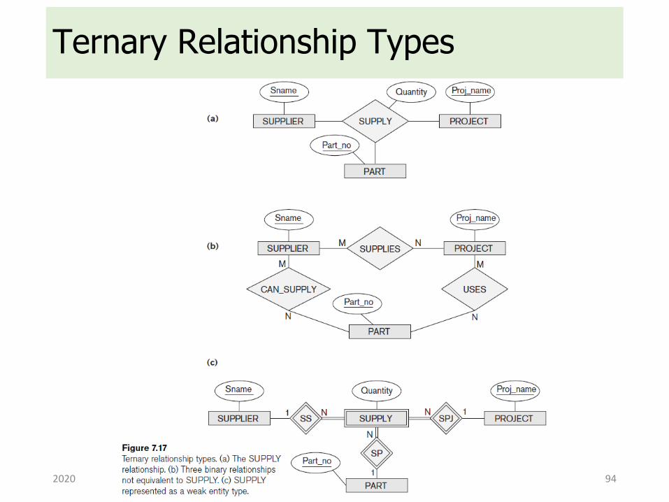
Ternary Relationship Types
2020 502052 - Chapter 4 94
Constraints on Higher-Degree• Notations for specifying structural constraints on n-ary
relationships
• Should both be used if it is important to fully specify structural constraints
2020 502052 - Chapter 4 95
ERD – Exercises
2020 502052 - Chapter 4 96
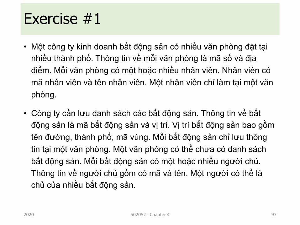
Exercise #1• Một công ty kinh doanh bất động sản có nhiều văn phòng đặt tại
nhiều thành phố. Thông tin về mỗi văn phòng là mã số và địađiểm. Mỗi văn phòng có một hoặc nhiều nhân viên. Nhân viên cómã nhân viên và tên nhân viên. Một nhân viên chỉ làm tại một vănphòng.
• Công ty cần lưu danh sách các bất động sản. Thông tin về bấtđộng sản là mã bất động sản và vị trí. Vị trí bất động sản bao gồmtên đường, thành phố, mã vùng. Mỗi bất động sản chỉ lưu thôngtin tại một văn phòng. Một văn phòng có thể chưa có danh sáchbất động sản. Mỗi bất động sản có một hoặc nhiều người chủ. Thông tin về người chủ gồm có mã và tên. Một người có thể làchủ của nhiều bất động sản.
2020 502052 - Chapter 4 97
END OF CHAPTER
502052 - Chapter 4 1012020


![[VNMATH.COM]-Duong thang-duong tron_Nguyen Tuan Lam.pdf](https://img.pdfslide.tips/doc/110x75/56d6beb31a28ab3016933955/vnmathcom-duong-thang-duong-tronnguyen-tuan-lampdf.jpg)


![[]Dinh-luong-duong khu+duong tong](https://img.pdfslide.tips/doc/110x75/55cf8541550346484b8c02b9/wwwfoodnkcomdinh-luong-duong-khuduong-tong-55d151db49696.jpg)


![[]Dinh-luong-duong khu+duong tong (1)](https://img.pdfslide.tips/doc/110x75/563dba84550346aa9aa65023/wwwfoodnkcomdinh-luong-duong-khuduong-tong-1.jpg)