Embed Size (px)
Citation preview
8/2/2019 Profibus Diagnostic
http://slidepdf.com/reader/full/profibus-diagnostic 1/10
8/2/2019 Profibus Diagnostic
http://slidepdf.com/reader/full/profibus-diagnostic 2/10
SIEMENS 05.11.2000
Seite 2/10 DP_OP_13_e.DOC
• CPU 318-2 DP• C7-626 DP (from 6ES7 626-2AG01-0AE3)• C7-633 DP and C7-634 DP• SINUMERIK 840D with integrated CPU315-2 DP (6ES7 315-2AF 01 -0AB0):
è FC125 not usbleè FB125 FB125 without detection of faulty slaves by Start/RESET
• SINUMERIK 840DI with integrated CPU315-2 DP (6ES7 315-2AF 03 -0AB0)• CPU 41x-2/3/4 DP• CP 443-5• IM 467 and IM 467 FO• WIN AC• WIN LC• Not for CP 342-5
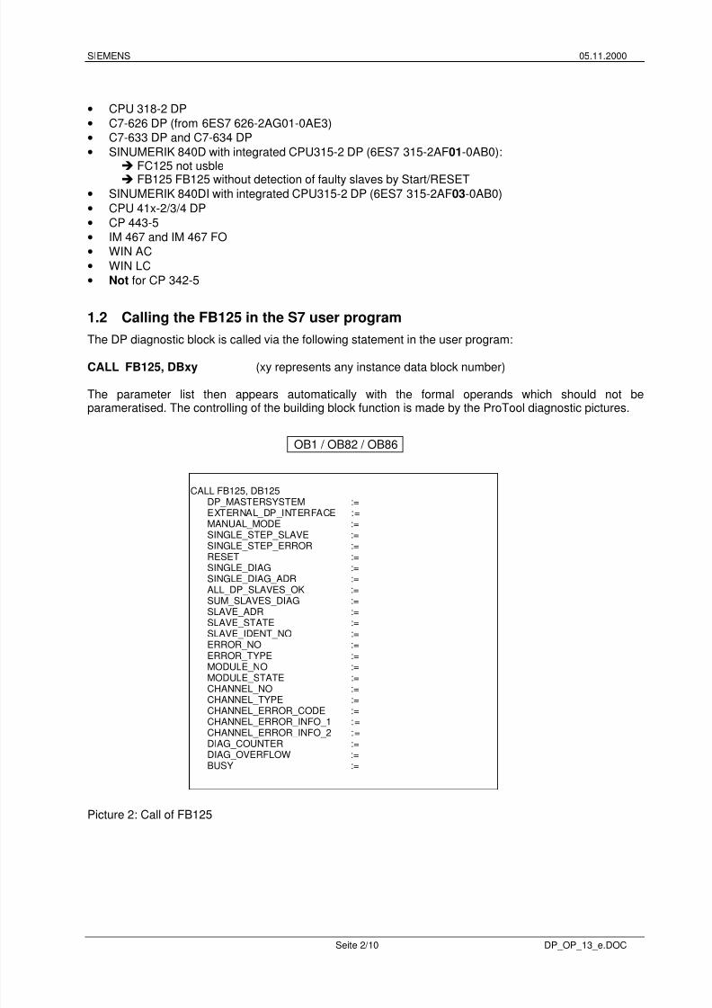
1.2 Calling the FB125 in the S7 user program The DP diagnostic block is called via the following statement in the user program:
CALL FB125, DBxy (xy represents any instance data block number) The parameter list then appears automatically with the formal operands which should not beparameratised. The controlling of the building block function is made by the ProTool diagnostic pictures.
Picture 2: Call of FB125
CALL FB125, DB125 DP_MASTERSYSTEM := EXTERNAL_DP_INTERFACE := MANUAL_MODE := SINGLE_STEP_SLAVE := SINGLE_STEP_ERROR := RESET := SINGLE_DIAG := SINGLE_DIAG_ADR := ALL_DP_SLAVES_OK := SUM_SLAVES_DIAG := SLAVE_ADR := SLAVE_STATE := SLAVE_IDENT_NO := ERROR_NO := ERROR_TYPE := MODULE_NO := MODULE_STATE := CHANNEL_NO := CHANNEL_TYPE := CHANNEL_ERROR_CODE := CHANNEL_ERROR_INFO_1 := CHANNEL_ERROR_INFO_2 := DIAG_COUNTER := DIAG_OVERFLOW := BUSY :=
OB1 / OB82 / OB86
8/2/2019 Profibus Diagnostic
http://slidepdf.com/reader/full/profibus-diagnostic 3/10
SIEMENS 05.11.2000
Seite 3/10 DP_OP_13_e.DOC
This call (including the same instance data block number and the same user actual operand) must bemade in the three execution levels OB1, OB82 and OB86 . A nested FB125 call in the three executionlevels is possible (e.g.: OB82 → FC120 → FB125). The order and the contents of the 20 bytes oftemporary local data of the organization blocks OB1, OB82 and OB86 must not be changed but can beextended at any time. The following SFCs are used internally in the FB125: SFC13 and SFC51 with SZL 0C91 (in the case of aninternal DP interface to the master CPU) or SZL 4C91 (in the case of an external DP interface to theCP/IM). It is not permissible to call SFC13 and/or SFC51 with SZL 0C91/4C91 in OB1 in addition to theFB125 call. Evaluation of the information at the block output parameters only makes sense in the cyclic programsection (OB1). The block FB125 will be processed orderly, if the BIE-Bit is set as “1”. And The BIE-Bit will be removed, ifthe processing of FB125 was error.
1.3 Technical specifications of FB125 Runtime without pending diagnostics message: depend on the DP master
e.g. CPU 315-2 DP as DP master: approx. 4ms Runtime with pending diagnostics message: depend on the DP master and the slave diagnostics
lengthe.g. CPU 315-2 DP as DP master: approx. 11ms
Memory used in the CPU: 5,8 Kbytes
8/2/2019 Profibus Diagnostic
http://slidepdf.com/reader/full/profibus-diagnostic 4/10
SIEMENS 05.11.2000
Seite 4/10 DP_OP_13_e.DOC
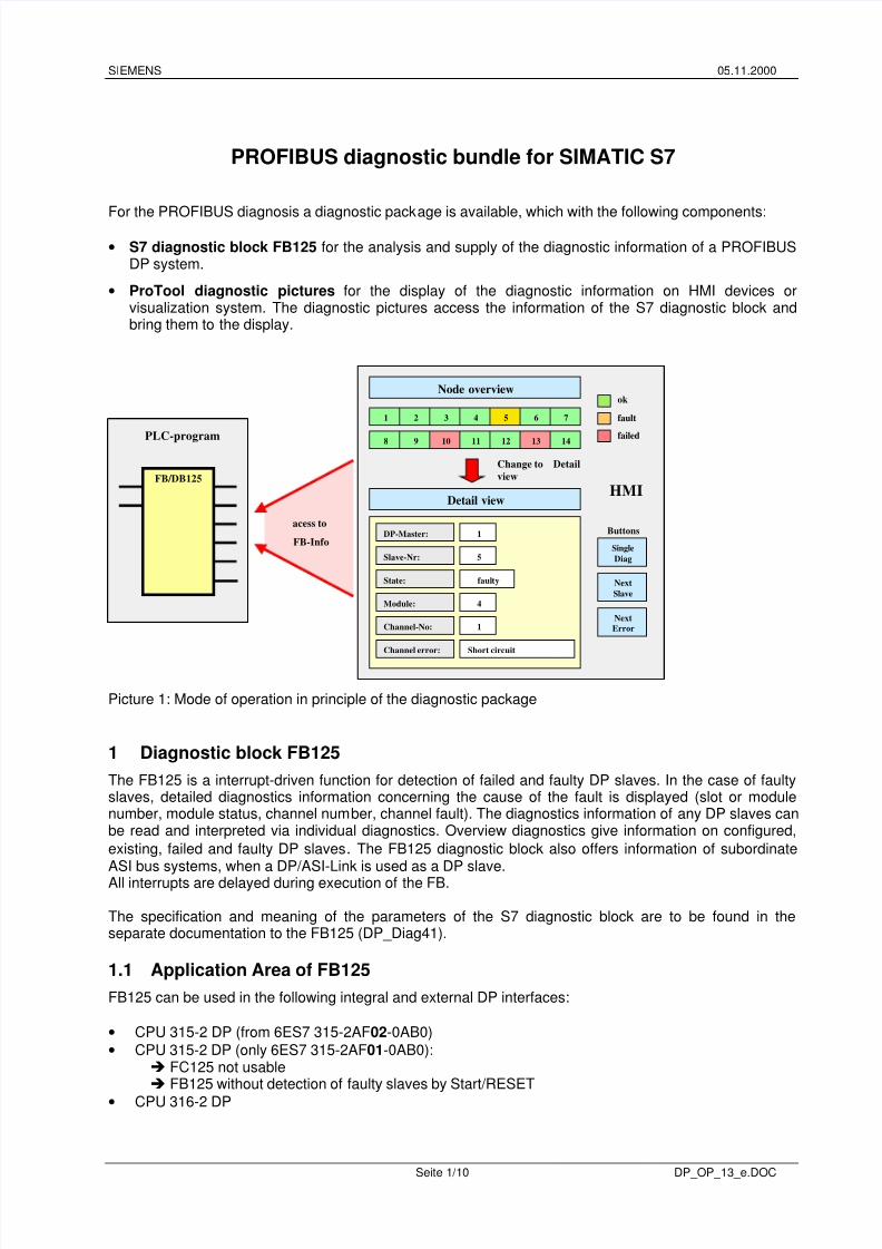
2 ProTool-Diagnostic picturesPROFIBUS Diagnostic pictures are supplied for the existing SIEMENS HMI devices. The tags of thepictures are assigned to data of the FB125-Instance data block. Text lists and graphics are provided as
well.
ProTool project engineering was created with ProTool/ProCS V5.2 + Service Pack 1
The diagnostic pictures available for the following HMI devices :
• OP 7• OP 012 (Sinumerik)• OP 17• OP 27• OP 37• TP 27• TP 37• MP 270• ProTool Runtime
2.1 PicturesName meaningDetailDiag Detailed -DiagnosticOverviewDiag Diagnostic overviewZ_SYSTEM_MEN Start-Picture (Standard picture)
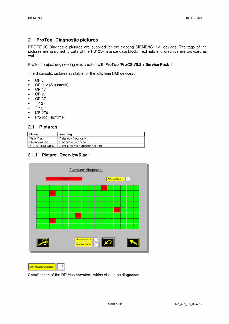
2.1.1 Picture „OverviewDiag“
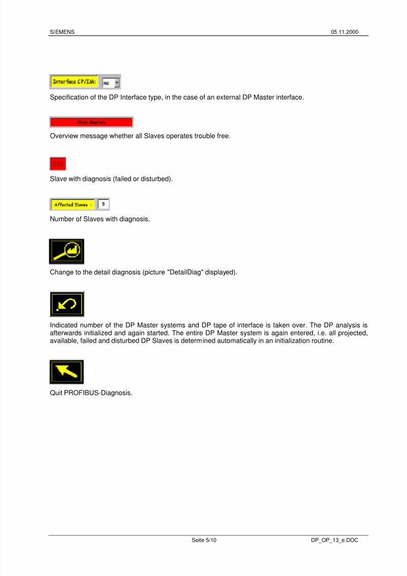
Specification of the DP Mastersystem, which should be diagnosed.
8/2/2019 Profibus Diagnostic
http://slidepdf.com/reader/full/profibus-diagnostic 5/10
8/2/2019 Profibus Diagnostic
http://slidepdf.com/reader/full/profibus-diagnostic 6/10
SIEMENS 05.11.2000
Seite 6/10 DP_OP_13_e.DOC
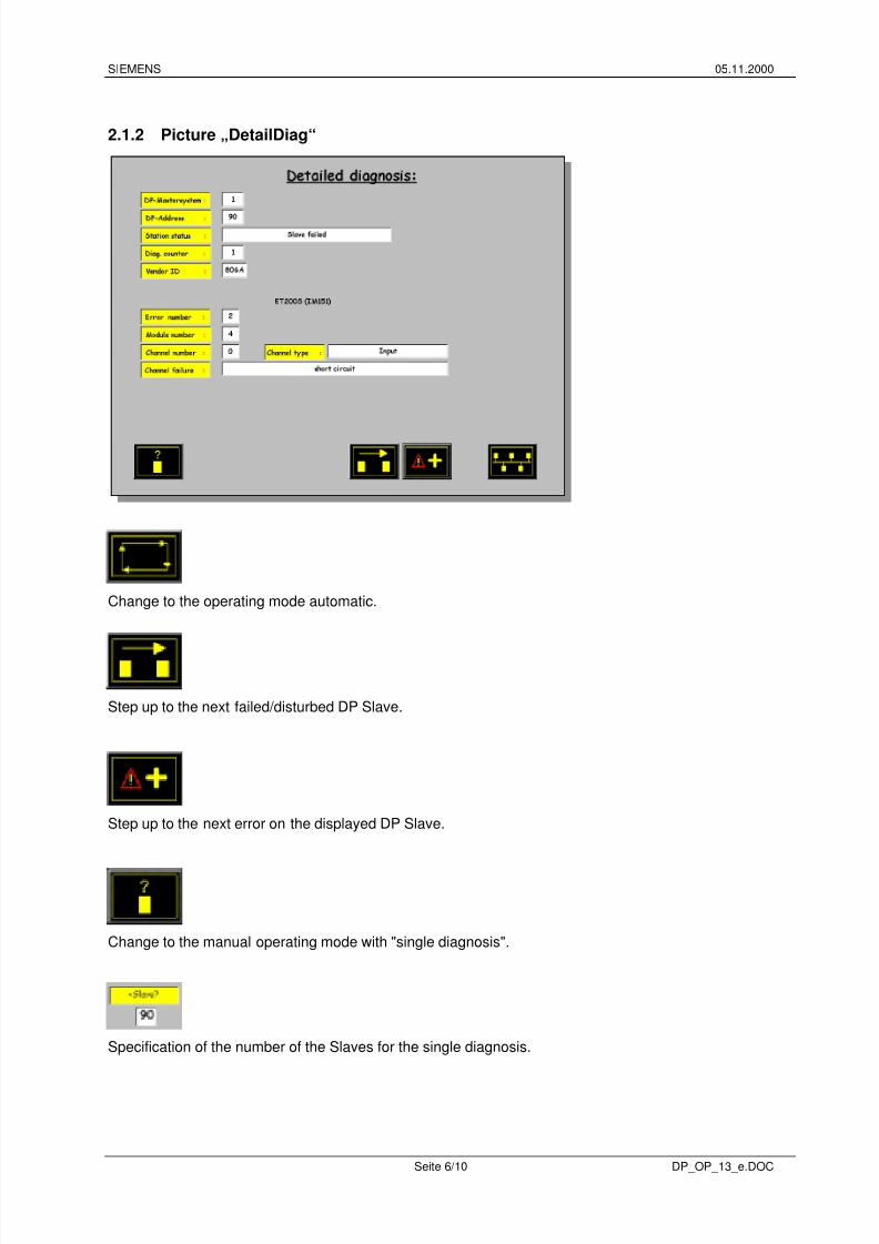
2.1.2 Picture „DetailDiag“
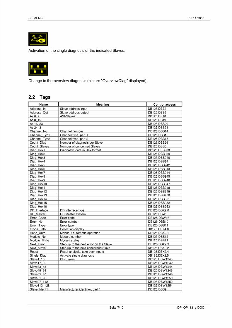
Change to the operating mode automatic.
Step up to the next failed/disturbed DP Slave.
Step up to the next error on the displayed DP Slave.
Change to the manual operating mode with "single diagnosis".
Specification of the number of the Slaves for the single diagnosis.
8/2/2019 Profibus Diagnostic
http://slidepdf.com/reader/full/profibus-diagnostic 7/10
8/2/2019 Profibus Diagnostic
http://slidepdf.com/reader/full/profibus-diagnostic 8/10
SIEMENS 05.11.2000
Seite 8/10 DP_OP_13_e.DOC
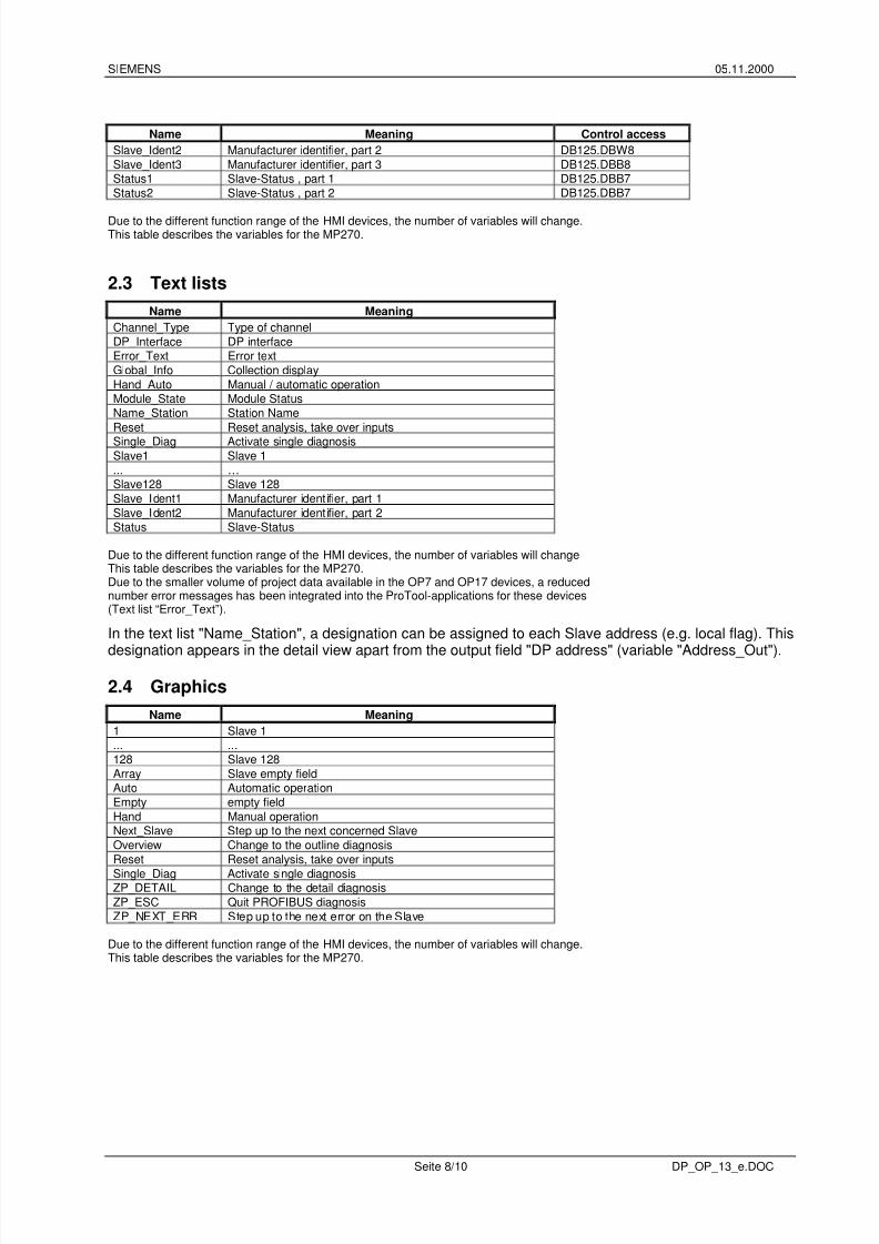
Name Meaning Control accessSlave_Ident2 Manufacturer identifier, part 2 DB125.DBW8Slave_Ident3 Manufacturer identifier, part 3 DB125.DBB8Status1 Slave-Status , part 1 DB125.DBB7Status2 Slave-Status , part 2 DB125.DBB7
Due to the different function range of the HMI devices, the number of variables will change.This table describes the variables for the MP270.
2.3 Text listsName Meaning
Channel_Type Type of channelDP_Interface DP interfaceError_Text Error textGlobal_Info Collection displayHand_Auto Manual / automatic operationModule_State Module StatusName_Station Station NameReset Reset analysis, take over inputsSingle_Diag Activate single diagnosisSlave1 Slave 1... …Slave128 Slave 128Slave_Ident1 Manufacturer identifier, part 1Slave_Ident2 Manufacturer identifier, part 2Status Slave-Status
Due to the different function range of the HMI devices, the number of variables will changeThis table describes the variables for the MP270.Due to the smaller volume of project data available in the OP7 and OP17 devices, a reducednumber error messages has been integrated into the ProTool-applications for these devices(Text list “Error_Text”).
In the text list "Name_Station", a designation can be assigned to each Slave address (e.g. local flag). This
designation appears in the detail view apart from the output field "DP address" (variable "Address_Out").
2.4 GraphicsName Meaning
1 Slave 1... ...128 Slave 128Array Slave empty fieldAuto Automatic operationEmpty empty fieldHand Manual operationNext_Slave Step up to the next concerned SlaveOverview Change to the outline diagnosisReset Reset analysis, take over inputsSingle_Diag Activate single diagnosisZP_DETAIL Change to the detail diagnosisZP_ESC Quit PROFIBUS diagnosisZP_NEXT_ERR Step up to the next error on the Slave
Due to the different function range of the HMI devices, the number of variables will change.This table describes the variables for the MP270.
8/2/2019 Profibus Diagnostic
http://slidepdf.com/reader/full/profibus-diagnostic 9/10
8/2/2019 Profibus Diagnostic
http://slidepdf.com/reader/full/profibus-diagnostic 10/10
SIEMENS 05.11.2000
Seite 10/10 DP_OP_13_e.DOC
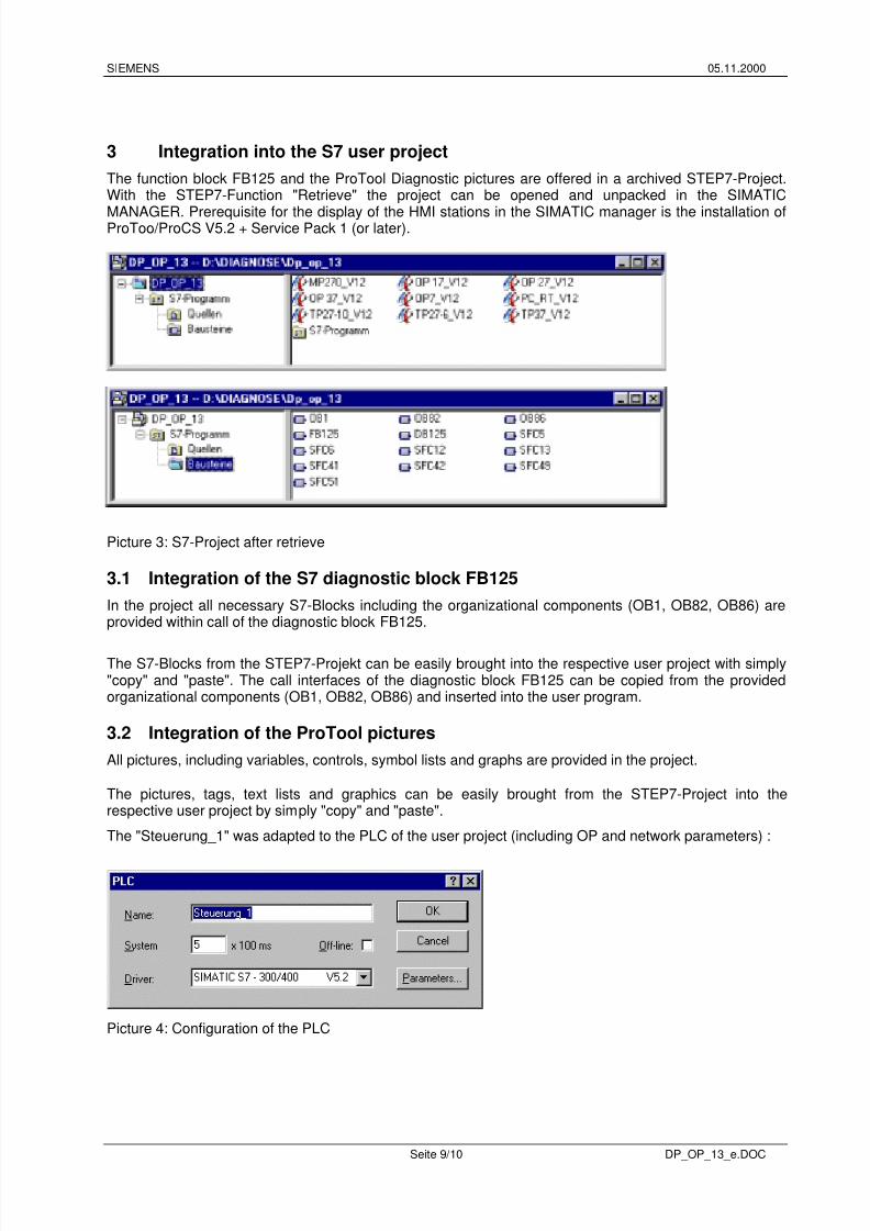
Picture 5: ProTool pro project engineering (example MP270)
3.3 Controlling of the FB125 with operands and HMI device If the FB125 needs to be controlled via operands (e.g. input / outputs) as well as via the HMI devices, thenproceed as follows :
• Supply of the parameter line of the FB125 with actual operands in the S7-User program.
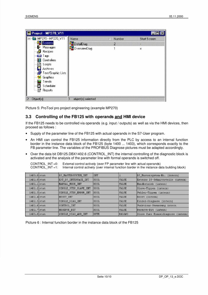
• An HMI can control the FB125 information directly from the PLC by access to an internal functionborder in the instance data block of the FB125 (byte 1400 ... 1403), which corresponds exactly to theFB parameter line. The variables of the PROFIBUS Diagnose pictures must be adapted accordingly.
• Over the data bit DB125.DBX1402.6 (CONTROL_INT) the internal controlling of the diagnostic block isactivated and the analysis of the parameter line with formal operands is switched off.
CONTROL_INT =0: External control actively (over FP parameter line with actual operands)CONTROL_INT =1: Internal control actively (over internal function border in the instance data building block)
Picture 6 : Internal function border in the instance data block of the FB125