Embed Size (px)
Citation preview
8/11/2019 Profile Wd m
http://slidepdf.com/reader/full/profile-wd-m 1/23
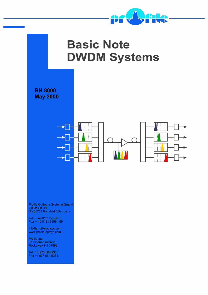
BN 8000May 2000
Profile Optische Systeme GmbHGauss Str. 11D - 85757 Karlsfeld / Germany
Tel + 49 8131 5956 - 0Fax
Profile Inc.87 Hibernia AvenueRockaway, NJ 07866
Tel +1 973 664-9385Fax
+ 49 8131 5956 - 99
+1 973 664-9384

8/11/2019 Profile Wd m
http://slidepdf.com/reader/full/profile-wd-m 2/23
Basics on DWDM systems
Summary 3
Basics on DWDM systems
Summary
Due to the internet boom the demand for transmission capacity isgrowing rapidly. Optical data transmission is the key to meet this re-quirement.
Principally, there are three possibilities to increase the transmissioncapacity: space division multiplex (deployment of further transmission
cables), time domain multiplex (increasing the data rate) and densewavelength division multiplex (transmitting several channels via onesinglemode fiber).
As in the wavelength range of 1280nm to 1650nm the technically use-able bandwidth of the singlemode fiber is 53THz, it is only consequentto take advantage of this large frequency range by using transmittersof different wavelengths.
This note describes the basic structure of a dense wavelength divisionmultiplex system and the requirements to the components of the sys-tem. Finally we talk about the most important measurements and have
a look at the prospects of future developments.
Contents
1 Two ways to high-bit rate systems...................................................................................... 32 Bandwidth and wavelength................................................................................................. 5
2.1 The transmission capacity of singlemode fibers........................................................... 52.2 DWDM wavelengths .................................................................................................... 6
3 Components of DWDM systems......................................................................................... 73.1 Laser sources .............................................................................................................. 73.2 Multiplexer and demultiplexer .................................................................................... 12
3.3 Singlemode fibers...................................................................................................... 153.4 Optical amplifiers....................................................................................................... 17
4 Measurements at DWDM systems ................................................................................... 194.1 Measuring the dispersion........................................................................................... 194.2 Spectral measurements............................................................................................. 204.3 Measuring the bit error rate........................................................................................ 21
5 Future developments........................................................................................................ 225.1 Extension of the wavelength range............................................................................ 225.2 Photonic nets............................................................................................................. 22
6. Literature......................................................................................................................... 23
Copyright
©©©©
2000, Profile GmbH

8/11/2019 Profile Wd m
http://slidepdf.com/reader/full/profile-wd-m 3/23
Basics on DWDM systems
1 Two ways to high-bit rate systems 3
1 Two ways to high-bit rate systems
By deploying additional fibers increasing data quantities can be trans- space division multiplex
mitted (SDM: Space Division Multiplex). This way to increase the
transmission capacity is very expensive and does not take any ad-vantage of the high transmission capacity of the singlemode fiber.
By time domain multiplex (TDM) the data rate transmitted via a single- time domain multiplex
mode fiber can be increased continuously corresponding to the knownhierarchies. The costs related to the data rate decrease with the in-crease in the level of hierarchy.
But there are certain limits to TDM: For transmission systems of 10Gbit/s and more, the requirements to the electronics are extremelydemanding and the required measurement technique is quite expen-
sive. These systems are still under development. At the moment thereseems to be no way to realize a 40 Gbit/s system with TDM only.
A number of physical effects do not allow a mere extrapolation of theprevious trends. Especially the requirements to the dispersion proper-ties at these data rates can hardly be fulfilled with already installed fi-bers.
Therefore starting from 2,5Gbit/s, combinations of time domain multi-
plex (TDM) and wavelength division multiplex (WDM) are used (fig. 1).The development has gone into the direction of DWDM systems
(Dense Wavelength Division Multiplex).
Figure 1: Two ways to high-bit data rate systems [1]
DWDM systems are an advancement of the classical WDM systems. dense wavelength
With classical WDM systems a few wavelengths (mostly two) are division multiplex
transmitted via a singlemode fiber.

8/11/2019 Profile Wd m
http://slidepdf.com/reader/full/profile-wd-m 4/23
Basics on DWDM systems
1 Two ways to high-bit rate systems 4
These wavelengths show a wide spectral distance from each other.They can be coupled into or decoupled from a singlemode fiber bymeans of conventional wavelength selective couplers (multiplexers /demultiplexers).
Thus, for example, a bi-directional or an unidirectional transmission viaa singlemode fiber is realized at wavelengths of 1,31µm and 1,55µm.
Whereas in classical WDM systems the transmission capacity mostlyonly doubles, in DWDM systems it increases for a factor n=4, 16, 32,64 or 128 depending on the configuration.
The specification nλ∗data rate in fig. 1 indicates, that n channels with
differing wavelengths are transmitted via a singlemode fiber with thespecified data rate.
By multiplexing many wavelengths in one fiber the transmission capa- increase in
city is increased. The logarithmic subdivision of the ordinate in fig. 1 transmission capacityshows the enormous increase in transmission capacity.
Besides the multiplication of the data rate in a single fiber, DWDMsystems have the advantage that the number of channels can be
adapted according to the actual demand. The provider of the trans-mission system does not have to invest today in transmission capacitythat may only be required some years later. Thus DWDM even getsattractive for the providers of smaller nets, for example, city nets.
In a DWDM system the light of laser diodes with wavelengths re-
commended by the ITU is launched into the inputs of a wavelength
multiplexer (MUX). At the output of the wavelength multiplexer allwavelengths are then combined and coupled into a singlemode fiber (fig. 2).
At the end of the transmission link the optical channels are separated
again by means of a wavelength demultiplexer (DMUX) and thus getto the different outputs.
In long transmission links it is necessary that the DWDM signals areoptically amplified by an optical fiber amplifier (OFA).
Figure 2: Set-up of a DWDM system (4 channels) with recommended points for reference measurements

8/11/2019 Profile Wd m
http://slidepdf.com/reader/full/profile-wd-m 5/23
Basics on DWDM systems
2 Bandwidth and wavelength 5
2 Bandwidth and wavelength
2.1 The transmission capacity of singlemode fibers
There is a correlation between the frequency f, the propagation velo-
city v („phase velocity“) and the wavelength λ ∗ :
v f = ⋅∗
λ (1)
In this the frequency f is determined by the processes during the
generation of radiation. The medium, in which the wave is propa-
gating, determines the phase velocity v. Consequently, the wave-
length λ ∗ is no independent quantity. It results from the frequency
and the phase velocity according to the equation (1).
Thus the light has the same frequency but different wavelengths indifferent substrates. For the propagation in a vacuum it is:
c f = ⋅λ (2)
In this, c is the vacuum velocity of light and λ the wavelength in thevacuum. All correlations stated in the following between frequency andwavelength refer to the wavelengths in the vacuum.
In principle, with the standard singlemode fiber for telecommunication
a wavelength range of approx. λ 1=1280nm to λ 2=1650nm can be uti-
lized. In this, the lower wavelength limit results from the core dia-meter of the singlemode fiber.
The upper wavelength limit results from the fact that above this limitthe attenuation coefficient rapidly increases and the fiber gets verysensitive regarding macro bending.
Corresponding to the equation (2) the resulting usable wavelength
range is from f 1=235THz to f 2=182THz. In this, THz=Terahertz=1012
oscillations per second. Thus the intrinsic transmission capacity of the
singlemode fiber is:
intrinsic
B f f THz= − =1 2 53 (3) transmission capacity
This transmission capacity is often called „bandwidth of the fiber“.
From the equation (3) it is obvious that the transmission capacity of
the singlemode fiber is only used at a very small scale at present. A2,5Gbit/s signal, for example, only uses this bandwidth capacity with0,005% and a 10Gbit/s signal with 0,02%!
It is obvious that the transmission capacity of a singlemode fiber can
be exploited much better by a simultaneous transmission of severalwavelengths.

8/11/2019 Profile Wd m
http://slidepdf.com/reader/full/profile-wd-m 6/23
Basics on DWDM systems
2 Bandwidth and wavelength 6
2.2 DWDM wavelengths
For several reasons it is currently not possible to make an unlimiteduse of the total wavelength range from 1280nm to 1650nm. For a rea-
sonable application of DWDM certain conditions have to be fulfilled.
Since DWDM systems are also used to built up long transmission
links, optical amplifiers have to be employed. These, however, areonly working well for the 3. and 4. optical window (about 1550nm to1610nm) today (see chapter 3.4).
The attenuation and the dispersion properties of a singlemode fiber are wavelength dependent, too. Thus the fibers cannot be used for allwavelengths.
Resulting from these restrictions, the frequencies given in table 1 were reference frequency:
recommended by the ITU [2] for DWDM transmission. The krypton 193.10THz
line at 193,10THz was considered to be the reference line, 100 GHz channel spacing:
was determined as channel spacing. 100GHz
These standardized frequencies will be maintained and only be sup-
plemented by additional frequencies, for example, for the wave-length range from 1565nm to 1610nm that becomes usable in con-nection with new optical fiber amplifiers.
Table 1 shows the standardized frequencies and the resulting wave-lengths in the vacuum according to the equation (2). For the vacuumvelocity of light 299792,458km/s were determined.
Fre-
quency/
THz
Center wave-
length/nm
Fre-
quency/
THz
Center wave-
length/nm
Fre-
quency/
THz
Center wave-
length/nm
195,9 1530,33 194,4 1542,14 192,9 1554,13
195,8 1531,12 194,3 1542,94 192,8 1554,94
195,7 1531,90 194,2 1543,73 192,7 1555,75
195,6 1532,68 194,1 1544,53 192,6 1556,55
195,5 1533,47 194,0 1545,32 192,5 1557,36
195,4 1534,25 193,9 1546,12 192,4 1558,17
195,3 1535,04 193,8 1546,92 192,3 1558,98195,2 1535,82 193,7 1547,72 192,2 1559,79
195,1 1536,61 193,6 1548,51 192,1 1560,61
195,0 1537,40 193,5 1549,32 192,0 1561,42
194,9 1538,19 193,4 1550,12 191,9 1562,23
194,8 1538,98 193,3 1550,92 191,8 1563,05
194,7 1539,77 193,2 1551,72 191,7 1563,86
194,6 1540,56 193,1 1552,52
194,5 1541,35 193,0 1553,33
Table 1: DWDM wavelength according to the ITU recommendation

8/11/2019 Profile Wd m
http://slidepdf.com/reader/full/profile-wd-m 7/23
Basics on DWDM systems
3 Components of DWDM systems 7
The channel spacing of 100 GHz in the 3. optical window results – ac-cording to the equation (2) – in an average wavelength spacing of 0,8nm.
Fig. 3 shows the multi-channel DWDM laser source PRO 8000 byProfile. Each PRO 8000 mainframe can be equipped with 8 laser source modules with wavelengths according to the ITU recommenda-tion (see table 1) and output powers from 10 to 40mW. Each laser
source can be tuned in wavelength via temperature for ± 0.85nm. Thedesired operating wavelength can be entered directly and is displayed.
Figure 3: Multi-channel DWDM laser source PRO 8000 by Profile
The PRO 8000 excels in its very high stability in output power (< 0,01dB) and wavelength stability (< 0,01nm) (see chapter 3.1).
3 Components of DWDM systems
3.1 Laser sources
DWDM transmission puts high demands to the components of the stabilized wavelength
system and their parameters. This especially concerns the outputwavelengths of the laser sources. The laser diodes must emit exactlyat the center wavelengths given in table 1.
Therefore the laser diode for the respective channel is selected indi-vidually. The preselected laser can then be fine-tuned to the exactcenter wavelength, for example, by changing the chip temperature.
To avoid interferences from adjacent transmission channels, the de-viations from the center frequencies are not allowed to be more than
± ⋅0 2, ∆f . At a frequency grid of ∆f=100GHz this corresponds to a tol-
erance of ±20GHz or ±0,16nm. That is why DWDM lasers have to beextremely stable in wavelength and must provide a small linewidth.

8/11/2019 Profile Wd m
http://slidepdf.com/reader/full/profile-wd-m 8/23
Basics on DWDM systems
3 Components of DWDM systems 8
The wavelength of the laser diode changes by aging (approx.
0,001nm to 0,01nm per year), by changes in temperature (approx.0,02nm/K to 0,1nm/K if the chip temperature changes and approx.
0,002nm/K if the package temperature changes) and by power back-
reflections into the laser (also refer to BN 1000: Basic Note Laser Di-odes).
Therefore, the laser temperature must be stabilized and power back-reflections into the light source must be minimized. Power back intothe light source is mainly due to back scattering within the fiber andalso due to backreflections at fiber splices and optical connectors.Backreflections at connectors can be reduced drastically by using
high-return-loss connectors, that provide angled end faces (8°) anda physical contact at the fiber end face.
Additionally an optical isolator can be installed directly behind the la-
ser chip. This isolator has a low insertion loss from the laser diode tothe fiber and a high insertion loss from the fiber to the laser diode.
DFB lasers (Distributed Feedback, refer to BN 1000) are well suited DFB laser
as laser sources for DWDM applications. A DFB laser emits highly
stable in singlemode with an extremely small linewidth (approx.0,0001nm) and can be tuned to the exact ITU center wavelength.
If a laser is direct modulated via the laser current, a disturbing effectoccurs:When the laser is switched on it will not immediately oscillate on itscenter wavelength (= carrier frequency) but it will take a finite time toreach it. This temporary effect, occurring at each fast enough change chirping
in current, is called chirping. Chirping may result in a broadening of thespectral linewidth of up to 0,2nm.
This broadening of the spectral linewidth has two big disadvan-tages (fig. 4):
• At dense DWDM systems with low channel spacing the broa-dened
spectrum may reach into the adjacent channel and result in inter-
ferences.
• The broadened signal is increasingly subjected to the chromatic chromatic dispersiondispersion. The chromatic dispersion results from the fact that lightof different wavelengths is propagating at different velocity in a fi-ber. Signal shares with higher frequency and signal shares withlower frequency do not arrive at the receiver at the same time. Sig-nal distortions are the result.

8/11/2019 Profile Wd m
http://slidepdf.com/reader/full/profile-wd-m 9/23
Basics on DWDM systems
3 Components of DWDM systems 9
Figure 4: Principle on how the signal is influenced by chirping and dispersion
With optical transmission the carrier of the information (= light) is influ-enced by the signal (= information) to be transmitted. The allocation of a signal to a carrier is achieved by modulation. The easiest way of modulation in DWDM systems is the direct modulation. The laser isswitched on and off (fig. 5).
Figure 5: Principle of direct modulation of a laser diode

8/11/2019 Profile Wd m
http://slidepdf.com/reader/full/profile-wd-m 10/23
Basics on DWDM systems
3 Components of DWDM systems 10
A better chirping behavior can be achieved by using for example EA-modulation
electro-absorption modulators.If an additional pn-junction is integrated in a DFB laser chip, the ab-sorption of the wave and thus the laser power can be controlled by anexternal electrical field applied to this pn-junction. This principle iscalled electro-absorption modulation (EA modulation) (fig. 6).
Figure 6: DFB laser with integrated EA modulator
Without this field being applied the light propagates in the fiber almostunattenuated. With the electrical field being applied the attenuation
strongly increases due to the Franz-Keldysh effect. The opticalpower is attenuated to only a few percent by amplitude modulation. EAmodulation excels in a clearly lower chirping compared to directmodulation.
The DWDM laser sources by Profile are available with either direct or EA modulation.
For higher modulation rates starting at 10 Gbit/s, there are further ex-ternal electro-optical modulators available. Their inner structure isbased on a Mach-Zehnder interferometer structure. Fig. 7 shows awaveguide structure embedded between electrodes.
U
Figure 7: Principle structure of an external electro-optical modulator
The launched light is divided into two identical light paths by a 3-dBcoupler. At the end of the modulator the light paths are combinedagain. An external electrical field changes the propagation time of the
light in one path. If the resulting difference in path lengths is λ /2, thetwo beams will superpose destructively. An extinction of the light is theconsequence.

8/11/2019 Profile Wd m
http://slidepdf.com/reader/full/profile-wd-m 11/23
Basics on DWDM systems
3 Components of DWDM systems 11
For reasons of completeness, two further modulation methods willbe given in the following. They are, however, only of subordinatemeaning for the DWDM technique.
The intensity of the light can also be influenced by using the Pockels Pockels effect
effect. Here the linearly polarized light of the laser source propagatesin an optically active medium. Depending on an applied electrical field
the polarization plane is rotated.
A polarizer located behind the active medium allows only that part of the light to continue which have the same state of polarization as of the polarizer.
With an acousto - optical modulator (AO modulator), a standing wave AO modulator
wave is generated in a quartz glass bloc by an intensity modulatedsound wave. This results in differences in density and the quartz blocwill react as a diffraction grating with a controllable efficiency.
Independent of the modulation method side frequencies will occur above and below the carrier frequency (= light). The width of the fre-
quency range covered by the side frequencies is defined as modula-
tion bandwidth. It depends on the signal frequency and on themodulation method.
The correlation between signal frequency and carrier frequency repre-sented in fig. 8 can be converted into a wavelength range via theequation (2).
Figure 8: Modulation bandwidth
Using all technical possibilities, for the transmission of a 2,5Gbit/s
signal a spectral bandwidth of at least 0,02nm is required. At a datarate of 10Gbit/s 0,08nm are required proportionally.
Fig. 9 shows the 0,8nm wavelength grid in DWDM systems, consider-ing the allowed tolerances of the center wavelengths and the modula-tion bandwidth required for a 10 Gbit/s modulation.

8/11/2019 Profile Wd m
http://slidepdf.com/reader/full/profile-wd-m 12/23
Basics on DWDM systems
3 Components of DWDM systems 12
Up to a 10Gbit/s modulation in observing the allowed wavelength tol-
erances there is an adequate "safety-distance" between the allowedwavelength ranges (50% of the channel distance).
The situation gets more critical if the channel spacing is reduced to itshalf (0,4nm). Then the allowed wavelength tolerance will also de-crease to its half.
Figure 9: Wavelength grid in a DWDM system
The stability demands to the laser sources have to be increased ac-cordingly. The safety-distance at a 10Gbit/s modulation is then re-
duced to only 40 %.
Should a wavelength drift away, caused, for example, by a change intemperature or a broadening of the spectral linewidth due to chirping,the safety-distance may decrease rapidly so that the channels will in-fluence each other.
As the safety-distances are rather small, a continuous monitoring of alltransmission channels (WDM monitoring) is imperative (see chapter 4.2).
3.2 Multiplexer and demultiplexer
Multiplexes and demultiplexers are key components in each DWDM multiplexer ⇔
system. Multiplexers (MUX) provide n optical inputs. Each input is demultiplexer
equipped with a selective filter for a certain wavelength.

8/11/2019 Profile Wd m
http://slidepdf.com/reader/full/profile-wd-m 13/23
Basics on DWDM systems
3 Components of DWDM systems 13
Figure 10: Multiplexer
The outputs of these filters are coupled to one singlemode fiber. At thereceiver the wavelengths are separated again by a demultiplexer (DMUX or DEMUX). Multiplexers and demultiplexers are identicalcomponents. The only difference is that they are driven in opposite di-rection (fig. 10).
A special type is the add/drop-multiplexer . With an add/drop-multiplexer new channels can be added to and other channels can bedropped off the transmission link (fig. 11).
Figure 11: Add/drop-multiplexer
These components are required because, in general, not all transmis-sion channels have the same start and destination. In future transpa-rent optical nets the add/drop-multiplexer will be a key component, too.

8/11/2019 Profile Wd m
http://slidepdf.com/reader/full/profile-wd-m 14/23
Basics on DWDM systems
3 Components of DWDM systems 14
Figure 12: Spectral behavior of two neighboring channels of a multiplexer (a) and definition of the most
important parameters (b): IL: insertion loss, PDL: polarization dependent loss, CS: cross talk
The center wavelengths of the multiplexer/demultiplexer have to be
adapted exactly to the standardized center wavelengths. Within thetolerance range of the transmission channel the optical multiplexer /demultiplexer must have a low insertion loss, outside a high insertionloss is required.
Fig. 12 (a) shows the spectral behavior of two neighboring channels of
the multiplexer. Typical parameters are the spectral width of the
transmission band, indicated by a 1dB-drop (BW(1dB)), and the filter
slope, characterized by a 20dB-drop (BW(20dB)).
Due to the non-ideal filter slope a defined spacing between the singlechannels is necessary.
The spectral width in the transmission band of the multiplexer / demul-tiplexer must be wider than the total spectral range required by the la-ser diode according to fig. 9. Then an insertion loss of <1dB per chan-nel is guaranteed.
For the examples given above, the range required by each channelwas 50 % or 60 % of the channel spacing. The ideal case for thetransmission band of a multiplexer would even be 80 %. However, thiscannot be realized yet.
In multiplexing as well as in demultiplexing the cross talk (CS) playsan important role. CS indicates that part of the power that couples over from an adjacent channel. It should be as low as possible.
Since the optical receivers are broad-banded, they cannot distinguishbetween the information signal and the cross talk. This may cause in-terferences and lead to a higher bit BER error rate. Demultiplexershave cross talk values of 25dB. More complex networks may requireup to 45dB.
8/11/2019 Profile Wd m
http://slidepdf.com/reader/full/profile-wd-m 15/23
Basics on DWDM systems
3 Components of DWDM systems 15
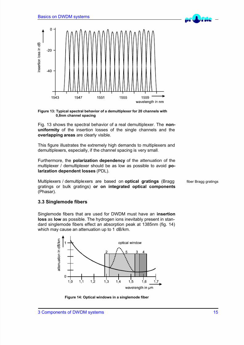
Figure 13: Typical spectral behavior of a demultiplexer for 20 channels with
0,8nm channel spacing
Fig. 13 shows the spectral behavior of a real demultiplexer. The non-
uniformity of the insertion losses of the single channels and the
overlapping areas are clearly visible.
This figure illustrates the extremely high demands to multiplexers anddemultiplexers, especially, if the channel spacing is very small.
Furthermore, the polarization dependency of the attenuation of the
multiplexer / demultiplexer should be as low as possible to avoid po-
larization dependent losses (PDL).
Multiplexers / demultiplexers are based on optical gratings (Bragg fiber Bragg gratings
gratings or bulk gratings) or on integrated optical components(Phasar).
3.3 Singlemode fibers
Singlemode fibers that are used for DWDM must have an insertion
loss as low as possible. The hydrogen ions inevitably present in stan-dard singlemode fibers effect an absorption peak at 1385nm (fig. 14)which may cause an attenuation up to 1 dB/km.
Figure 14: Optical windows in a singlemode fiber
8/11/2019 Profile Wd m
http://slidepdf.com/reader/full/profile-wd-m 16/23
Basics on DWDM systems
3 Components of DWDM systems 16
If the so-called 5. optical window is to be used, a special fiber, the all- all-wave-fiber
wave-fiber, is to be used. In this fiber the absorption peak is sup-pressed by a special technology.
As already mentioned in chapter 3.1, most singlemode fibers show achromatic dispersion. Since chromatic dispersion leads to increasingsignal distortions with increasing transmission distance, a fiber with avery low, or even better, none dispersion must be used.
At real fibers it can be recognized that the dispersion can fluctuate ex-
tremely and may also show zero crossings.
Therefore, for certain wavelength ranges of a singlemode fiber thetransmission is hardly influenced by chromatic dispersion. Other ranges cannot be used with the present methods of data transmission.
However, research has recently found methods that enable to use also
these wavelength ranges. Due to the Soliton management, signaltransmissions with high data rates have been enabled for wavelengthranges that could not be used before.
Despite this fact, with already installed fibers, the transmission of highdata rates can only be realized in wavelength ranges where the dis-persion is almost zero.
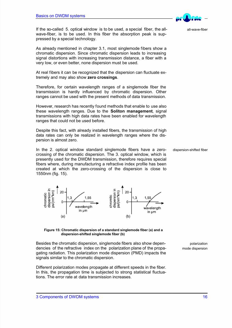
In the 2. optical window standard singlemode fibers have a zero- dispersion-shifted fiber
crossing of the chromatic dispersion. The 3. optical window, which ispresently used for the DWDM transmission, therefore requires specialfibers where, during manufacturing a refractive index profile has been
created at which the zero-crossing of the dispersion is close to1550nm (fig. 15).
Figure 15: Chromatic dispersion of a standard singlemode fiber (a) and a
dispersion-shifted singlemode fiber (b)
Besides the chromatic dispersion, singlemode fibers also show depen- polarization
dencies of the refractive index on the polarization plane of the propa- mode dispersion
gating radiation. This polarization mode dispersion (PMD) impacts thesignals similar to the chromatic dispersion.
Different polarization modes propagate at different speeds in the fiber.In this, the propagation time is subjected to strong statistical fluctua-tions. The error rate at data transmission increases.

8/11/2019 Profile Wd m
http://slidepdf.com/reader/full/profile-wd-m 17/23
Basics on DWDM systems
3 Components of DWDM systems 17
Really disagreeable with the PMD is the fact that it strongly dependson external influences and that it fluctuates statistically (also refer toBN 9000 “Basic Note PMD and Polarization”). The influence of thePMD on the transmission safety gets serious at data rates of morethan 2,5Gbit/s. High-bit rate transmission systems should thereforehave a PMD compensation for all transmission channels.
Basically, all components used in DWDM systems should be polariza-tion independent.
Besides the linear effects, for example the dispersion, also non-linear
effects occur in singlemode fibers. Certain properties of the fiber willchange, dependent on the field intensity caused by the propagatinglight.
One of these effects is the four wave mixing. It occurs if several chan- four wave mixing
nels are transmitted simultaneously via a singlemode fiber and must
therefore be considered in DWDM systems.
In singlemode fibers the laser light is concentrated in the very smallcore. This causes high electric field intensities and leads to interac-tions between light and the substrate which can only be explained with
the laws of the non-linear optics.
The impact of the non-linearity is low. But it can sum up over longtransmission distances if the waves are synchronous in phase.
This synchronism of phases can be disturbed and thus the effect of the four wave mixing be suppressed if the transmission is outside the
zero-crossing of the chromatic dispersion. Therefore the chromaticdispersion should be outside the range from +0,8ps/(nm km) to -
0,8ps/(nm km).
For this reason the non-zero dispersion fiber has been developedfor high-bit rate DWDM. With this non-zero dispersion fiber it is possi-ble to use an extended wavelength range up to 1620nm (4. opticalwindow, see fig. 14) by suppressing the four wave mixing.
3.4 Optical amplifiers
Since DWDM systems are used for long transmission links, the signalmust be amplified after a certain fiber length.
The amplification can be done with an electrical repeater. A repeater electrical repeater
converts the optical signal by means of a photodiode into an electricalsignal, amplifies the electrical signal and converts it back to an opticalsignal.
Fig. 16 (a) shows a 1-channel system above and a DWDM system
below with electrical amplification.

8/11/2019 Profile Wd m
http://slidepdf.com/reader/full/profile-wd-m 18/23
Basics on DWDM systems
3 Components of DWDM systems 18
You will recognize that within the multi-channel system each single
channel requires a separate opto-electrical transformation, amplifica-tion and electro-optical transformation back. Thus, for an n channelsystem n repeaters are required.
Figure 16: 1-channel system (above) and DWDM system (below) with electrical (a)
or optical (b) signal amplification
A further disadvantage is that with a given repeater only a given proto-col at a fixed data rate can be transmitted. Therefore it is more rea-sonable to use optical amplifiers in DWDM systems.
Fig. 16 (b) shows a 1-channel system above and a DWDM system fiber optic amplifier below with optical amplification. In comparing the two multi-channel
DWDM systems the superiority of using an optical amplifier be-
comes obvious.
The optical amplification is independent of the bit rate as well as of the transmission capacity. Thus, optical amplifiers are of special inter-est for DWDM systems. Furthermore, the optical amplifier is inde-pendent of the data protocol. It operates without converting the signalinto the electrical range.
Until now optical amplifiers with appropriate features have been
available for the 3. optical window only. Suitable optical amplifiers for
the 4. optical window are being developed now. Therefore, DWDMsystems can soon be realized in the 3. and the 4. optical window up to L-band
1610nm (L-band, long wavelength).
The usable wavelength range for DWDM systems thus strongly de-pends on the availability of appropriate optical amplifiers.
Analyses found out that DWDM systems show a clear advantage inprice in comparison to TDM systems if larger transmission distanceshave to be covered where an amplification is necessary.
8/11/2019 Profile Wd m
http://slidepdf.com/reader/full/profile-wd-m 19/23
Basics on DWDM systems
4 Measurements at DWDM systems 19
Up till now, mainly fiber optic amplifiers for the 3. optical window
around 1550nm have been on the market, the so-called EDFAs (Er-
bium Doped Fiber Amplifier). Nowadays also amplifiers for the wave-
length range from 1565nm to 1610nm are being developed. Differ-ent principles of amplification are here being discussed.
Fiber amplifiers for the 2. optical window around 1310nm are still inthe stage of research, for example by using praseodymium doped
fluoride fibers (PDFA: Praseodymium Doped Fiber Amplifier).
4 Measurements at DWDM systems
4.1 Measuring the dispersion
In singlemode fibers the chromatic dispersion is the dominating kindof dispersion at low data rates. The measurement set-up to charac-terize the chromatic dispersion is sophisticated and expensive. A suit-able field measurement method is not available. Usually the chromaticdispersion is not measured at installed fibers.
The chromatic dispersion is normally specified by the manufacturer of the transmission cable. Due to improper deployment of the cable theattenuation of the single fibers may increase, the dispersion, however,will rather decrease.
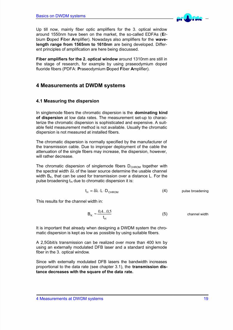
The chromatic dispersion of singlemode fibers DCHROM together with
the spectral width δλ of the laser source determine the usable channelwidth BK, that can be used for transmission over a distance L. For thepulse broadening tH due to chromatic dispersion it is:
t L DH CHROM= ⋅ ⋅δλ (4) pulse broadening
This results for the channel width in:
Bt
K
H
~, ... ,0 4 0 5
(5) channel width
It is important that already when designing a DWDM system the chro-matic dispersion is kept as low as possible by using suitable fibers.
A 2,5Gbit/s transmission can be realized over more than 400 km byusing an externally modulated DFB laser and a standard singlemodefiber in the 3. optical window.
Since with externally modulated DFB lasers the bandwidth increases
proportional to the data rate (see chapter 3.1), the transmission dis-
tance decreases with the square of the data rate.

8/11/2019 Profile Wd m
http://slidepdf.com/reader/full/profile-wd-m 20/23
Basics on DWDM systems
4 Measurements at DWDM systems 20
Consequently, in a 10 Gbit/s transmission via a standard singlemodefiber the chromatic dispersion will already have a limiting effect after approx. 25 km.
Then, for a transmission in the 3. optical window a dispersion-shifted
fiber or a non-zero dispersion fiber is required.
Besides the chromatic dispersion the polarization mode dispersion polarization
(also refer to BN 9000) may cause signal distortions. With the PAT mode dispersion
9000 B Profile offers a sophisticated measurement system for reliableevaluation of the PMD.
The PMD of common singlemode fibers normally enables a transmis-sion of up to 2,5Gbit/s over 100 km without problems.
During the production of modern fibers an oscillating, stress-free
twist is introduced into the fiber. This forces a strong coupling of all
modes. It results in a decrease in the absolute values and in a de-crease in the fluctuations of the PMD. These fibers enable a 10Gbit/stransmission over more than 400km.
However, the PMD is subjected to strong statistical fluctuations thatcan influence the transmission quality considerably. Therefore, a PMDcompensation at the receiving end is imperative if already installed fi-bers are to be used to transmit data rates of more than 2,5Gbit/s. Pro-file will be offering a suitable PMD compensator soon.
4.2 Spectral measurements
During installation and operation of a DWDM system continuous spectral management
spectral measurements are required. This is called spectral ma-nagement.
For this purpose defined measurement points are recommended inthe DWDM system (see fig. 2). These measurement points should berecommended by the supplier of the DWDM system and must be lowin backreflections.
DWDM systems are very complex. Although the manufacturers
specify their components, the installation in the field may deterioratetheir properties. Tolerances in the parameters as well as interactionsbetween the components may influence the transmission qualitynegatively.
By using an optical spectrum analyzer (OSA) various measure- optical spectrum analyzer
ments can be done. It is possible to determine the single wavelengthsand their drifts. The optical power of each channel and the total power can be measured. And it is also possible to measure the differences inpower between the single channels. Finally with an OSA the signal-to-noise ratio and the cross talk can be determined (fig. 17).

8/11/2019 Profile Wd m
http://slidepdf.com/reader/full/profile-wd-m 21/23
Basics on DWDM systems
4 Measurements at DWDM systems 21
Figure 17: Typical DWDM spectrum
Also during operating a DWDM system all these parameters have to WDM monitor
be monitored continuously. The reason is rather simple: if an error oc-curs on one transmission channel, for example the complete failure of a laser source, the provider of the transmission link must be able toswitch this channel to a standby channel quickly (< 50ms).
4.3 Measuring the bit error rate
In addition to the signal-to-noise ratio it is necessary to measure thedispersion depending differential group delay at high-bit data rates.
Each single channel is characterized by its own bit error rate.Therefore, for a bit error rate measurement the single channels haveto be selected.
This may be done by means of a spectrometer if it disposes of an op-
tical output. The spectrometer will then have the effect of a tunable
demultiplexer (fig. 18).
Figure 18: Bit error rate measurement in a DWDM system
The growing demands to the bit error rates and the increasing number of channels result in very time consuming measurements.

8/11/2019 Profile Wd m
http://slidepdf.com/reader/full/profile-wd-m 22/23
Basics on DWDM systems
5 Future developments 22
5 Future developments
5.1 Extension of the wavelength range
Current trends aim at a better utilization of the intrinsic bandwidth of the singlemode fiber. This can be achieved in two ways:
One way is to decrease the channel spacing. Presently standardized decreasing the
and mainly applied are DWDM systems with a channel spacing of channel spacing
100GHz (see table 1).
Recent experiments try to reduce the channel spacing to 50GHz.However, this drastically increases the demands to all components of the system.
The other way is to open up to a larger wavelength range for trans-extending the
mission. The corresponding possibilities have already been described wavelength range
in chapter 3.
If DWDM systems are operated together with optical amplifiers, the C-band
so-called C-band is available for the wavelength range from 1530nm L-band
to 1560 nm and the so-called L-band for the range from 1565nm to1610nm. The multi-channel laser source PRO 8000 by Profile is al-ready available with laser sources in the L-band.
If the DWDM system is operated without optical amplifiers, the totalsinglemode wavelength range from 1280nm to 1650nm could be used.
However, suitable laser sources are not available yet for the totalrange. Furthermore, a fiber with minimized attenuation and dispersionproperties that avoids non-linear effects must be used for the respec-tive wavelength range (see chapter 3.3).
5.2 Photonic nets
At present, DWDM systems are mainly used for point-to-point trans-missions. In future, photonic nets will be installed. Data will then betransmitted optically only.
If both, transmission and routing are effected optically, the net will be optically transparentoptically transparent. There will be no opto-electronic interface bet-ween transmitter and receiver anymore.
The installation of photonic nets requires the development of special,highly sophisticated techniques and components. The following com-ponents will be a must for future photonic nets:
• Add/drop-multiplexers
• Routing modules: enable signal distribution
• Optical cross connectors: switch optical signals of any input linesto any output lines by means of mechanical, optical or thermo-
optical methods• Dispersion compensating components

8/11/2019 Profile Wd m
http://slidepdf.com/reader/full/profile-wd-m 23/23
Basics on DWDM systems
6 Literat re 23
6. Literature
[1] Flanigan, Barry: Carriers choose WDM to surf the ‘data wave’. Fibre Systems, 2(1998), September, page 17, 19, 20.
[2] ITU -T-Recommendation G.692: Optical Interfaces for MultichannelSystems with Optical Amplifiers.