Embed Size (px)
Citation preview

DEIF A/S · Frisenborgvej 33 · DK-7800 Skive · Tel.: +45 9614 9614 · Fax: +45 9614 9615 · [email protected] · www.deif.com
DEIF A/S · Frisenborgvej 33 · DK-7800 Skive · Tel.: +45 9614 9614 · Fax: +45 9614 9615 · [email protected] · www.deif.com
DEIF A/S · Frisenborgvej 33 · DK-7800 Skive · Tel.: +45 9614 9614 · Fax: +45 9614 9615 · [email protected] · www.deif.com
OPERATOR'S MANUAL
Protection and Power Management, PPM-3● Display and push-button functions● Alarm handling● Log list● Failure mode and effect analysis
Document no.: 4189340673ASW version: 3.0x.x or later
1. General information1.1. Warnings, legal information and safety..................................................................................................4
1.1.1. Warnings and notes ......................................................................................................................41.1.2. Legal information and disclaimer ..................................................................................................41.1.3. Safety issues ................................................................................................................................41.1.4. Electrostatic discharge awareness ...............................................................................................41.1.5. Factory settings ............................................................................................................................4
1.2. About the Operator's Manual..................................................................................................................51.2.1. General purpose ...........................................................................................................................51.2.2. Intended users ..............................................................................................................................51.2.3. Contents and overall structure ......................................................................................................5
2. Display unit and menu structure2.1. Preface...................................................................................................................................................62.2. Display unit (DU-2).................................................................................................................................6
2.2.1. Diesel generator (DG) display unit.................................................................................................62.2.2. Shaft Generator (SG)/Shore Connection (SC) display unit...........................................................62.2.3. Bus Tie Breaker (BTB) display unit................................................................................................72.2.4. Emergency Diesel Generator (EDG) display unit..........................................................................7
2.3. Push-button and LED functions..............................................................................................................82.3.1. Push-buttons and LED...................................................................................................................8
2.4. Menu structure.....................................................................................................................................122.4.1. Menu structure.............................................................................................................................122.4.2. Entry window...............................................................................................................................132.4.3. View menu...................................................................................................................................132.4.4. View menu navigation..................................................................................................................132.4.5. View window 1 (V1).....................................................................................................................142.4.6. View window 2 (V2).....................................................................................................................142.4.7. View window 3 (V3).....................................................................................................................142.4.8. Setup menu.................................................................................................................................14
2.5. Text in the display................................................................................................................................162.5.1. Display texts................................................................................................................................16
2.6. Mode overview.....................................................................................................................................182.6.1. Overview of modes......................................................................................................................18
2.7. Mode selection.....................................................................................................................................182.7.1. Selection of mode........................................................................................................................18
2.8. Password..............................................................................................................................................182.8.1. Password levels...........................................................................................................................182.8.2. Parameter access........................................................................................................................20
3. Alarm handling and log list3.1. Alarm handling.....................................................................................................................................21
3.1.1. How to handle alarms .................................................................................................................213.2. Log list..................................................................................................................................................21
3.2.1. Log and event list.........................................................................................................................21
4. Service menu4.1. Service menu overview........................................................................................................................23
4.1.1. Present operating condition.........................................................................................................23
5. Parameter setup5.1. About parameter setup.........................................................................................................................255.2. Finding the selected parameter............................................................................................................25
5.2.1. How to find the correct parameter...............................................................................................255.3. Parameter descriptions........................................................................................................................25
5.3.1. Description of parameters............................................................................................................255.4. Setup....................................................................................................................................................26
5.4.1. Parameter setup..........................................................................................................................26
PPM-3 operators manual 4189340673 UK
DEIF A/S Page 2 of 27

6. Failure mode and effect analysis6.1. Troubleshooting....................................................................................................................................27
6.1.1. Failure detection and correction..................................................................................................27
PPM-3 operators manual 4189340673 UK
DEIF A/S Page 3 of 27
1. General information1.1 Warnings, legal information and safety
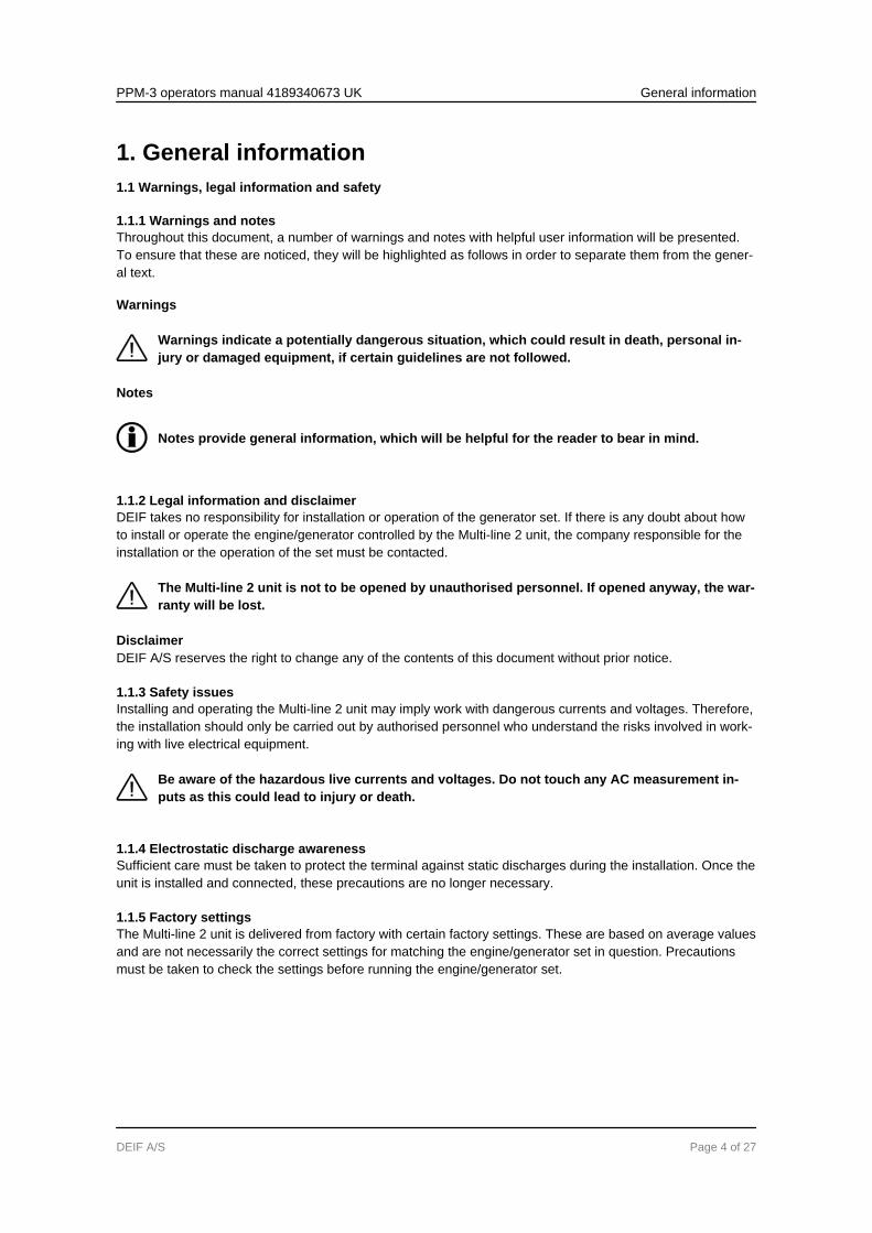
1.1.1 Warnings and notesThroughout this document, a number of warnings and notes with helpful user information will be presented.To ensure that these are noticed, they will be highlighted as follows in order to separate them from the gener-al text.
Warnings
Warnings indicate a potentially dangerous situation, which could result in death, personal in-jury or damaged equipment, if certain guidelines are not followed.
Notes
Notes provide general information, which will be helpful for the reader to bear in mind.
1.1.2 Legal information and disclaimerDEIF takes no responsibility for installation or operation of the generator set. If there is any doubt about howto install or operate the engine/generator controlled by the Multi-line 2 unit, the company responsible for theinstallation or the operation of the set must be contacted.
The Multi-line 2 unit is not to be opened by unauthorised personnel. If opened anyway, the war-ranty will be lost.
DisclaimerDEIF A/S reserves the right to change any of the contents of this document without prior notice.
1.1.3 Safety issuesInstalling and operating the Multi-line 2 unit may imply work with dangerous currents and voltages. Therefore,the installation should only be carried out by authorised personnel who understand the risks involved in work-ing with live electrical equipment.
Be aware of the hazardous live currents and voltages. Do not touch any AC measurement in-puts as this could lead to injury or death.
1.1.4 Electrostatic discharge awarenessSufficient care must be taken to protect the terminal against static discharges during the installation. Once theunit is installed and connected, these precautions are no longer necessary.
1.1.5 Factory settingsThe Multi-line 2 unit is delivered from factory with certain factory settings. These are based on average valuesand are not necessarily the correct settings for matching the engine/generator set in question. Precautionsmust be taken to check the settings before running the engine/generator set.
PPM-3 operators manual 4189340673 UK General information
DEIF A/S Page 4 of 27
1.2 About the Operator's Manual
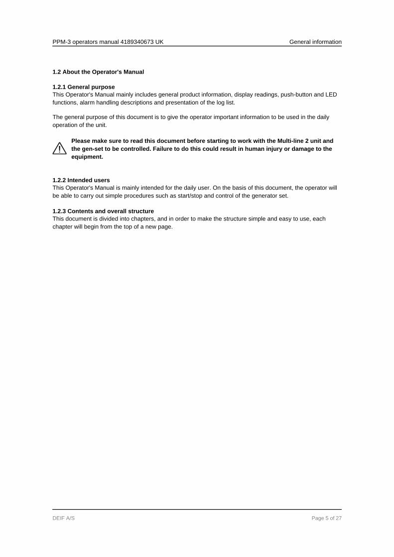
1.2.1 General purposeThis Operator's Manual mainly includes general product information, display readings, push-button and LEDfunctions, alarm handling descriptions and presentation of the log list.
The general purpose of this document is to give the operator important information to be used in the dailyoperation of the unit.
Please make sure to read this document before starting to work with the Multi-line 2 unit andthe gen-set to be controlled. Failure to do this could result in human injury or damage to theequipment.
1.2.2 Intended usersThis Operator's Manual is mainly intended for the daily user. On the basis of this document, the operator willbe able to carry out simple procedures such as start/stop and control of the generator set.
1.2.3 Contents and overall structureThis document is divided into chapters, and in order to make the structure simple and easy to use, eachchapter will begin from the top of a new page.
PPM-3 operators manual 4189340673 UK General information
DEIF A/S Page 5 of 27
2. Display unit and menu structure2.1 Preface
This chapter deals with the display unit including the push-button and LED functions. In addition, the unitmenu structure will be presented.
2.2 Display unit (DU-2)
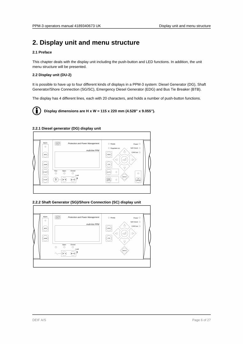
It is possible to have up to four different kinds of displays in a PPM-3 system: Diesel Generator (DG), ShaftGenerator/Shore Connection (SG/SC), Emergency Diesel Generator (EDG) and Bus Tie Breaker (BTB).
The display has 4 different lines, each with 20 characters, and holds a number of push-button functions.
Display dimensions are H x W = 115 x 220 mm (4.528” x 9.055”).
2.2.1 Diesel generator (DG) display unit
Protection and Power Management
multi-line PPM
Self check
CAN bus
Ready
Regulator on
JUMP
START
INFO
STOP
Alarm
VIEW
LOG
AUTO
AUTOSEMI 1st
PRIOR
BACK
G
Load
ClosedOpenRun
Power
2.2.2 Shaft Generator (SG)/Shore Connection (SC) display unit
Protection and Power Management
multi-line PPM
Self check
CAN bus
Ready
JUMP
INFO
Alarm
VIEW
LOG
BACK
ClosedOpen
Power
Load
PPM-3 operators manual 4189340673 UK Display unit and menu structure
DEIF A/S Page 6 of 27
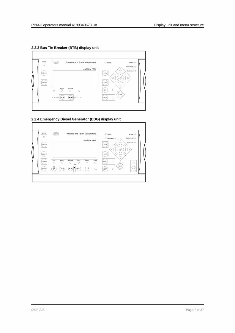
2.2.3 Bus Tie Breaker (BTB) display unit
Protection and Power Management
multi-line PPM
Self check
CAN bus
Ready
JUMP
INFO
Alarm
VIEW
LOG
DG
SG/SC
BACK
ClosedOpen
Power
2.2.4 Emergency Diesel Generator (EDG) display unit
Protection and Power Management
multi-line PPM
Self check
CAN bus
Ready
Regulator on
JUMP
START
INFO
STOP
Alarm
VIEW
LOG
AUTO
AUTOSEMI
TEST
BACK
G
Load
ClosedOpen Open Closed MBBRun
Power
PPM-3 operators manual 4189340673 UK Display unit and menu structure
DEIF A/S Page 7 of 27
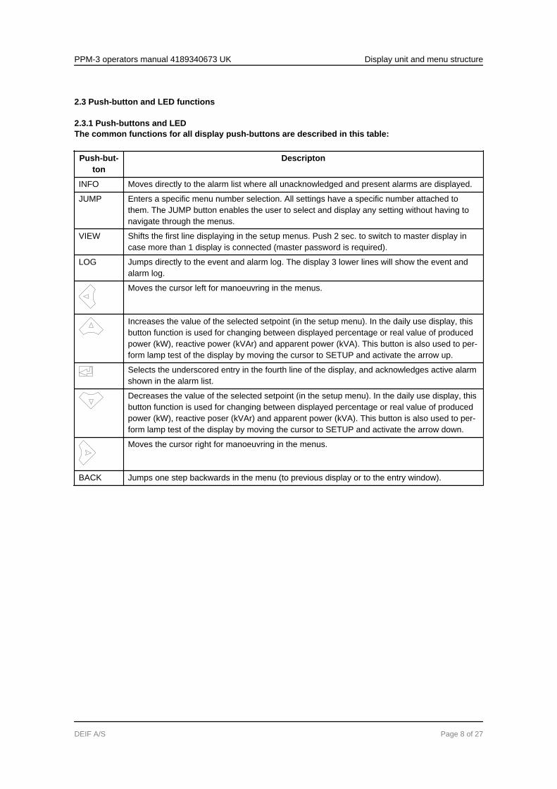
2.3 Push-button and LED functions
2.3.1 Push-buttons and LEDThe common functions for all display push-buttons are described in this table:
Push-but-ton
Descripton
INFO Moves directly to the alarm list where all unacknowledged and present alarms are displayed.
JUMP Enters a specific menu number selection. All settings have a specific number attached tothem. The JUMP button enables the user to select and display any setting without having tonavigate through the menus.
VIEW Shifts the first line displaying in the setup menus. Push 2 sec. to switch to master display incase more than 1 display is connected (master password is required).
LOG Jumps directly to the event and alarm log. The display 3 lower lines will show the event andalarm log.
Moves the cursor left for manoeuvring in the menus.
Increases the value of the selected setpoint (in the setup menu). In the daily use display, thisbutton function is used for changing between displayed percentage or real value of producedpower (kW), reactive power (kVAr) and apparent power (kVA). This button is also used to per-form lamp test of the display by moving the cursor to SETUP and activate the arrow up.
Selects the underscored entry in the fourth line of the display, and acknowledges active alarmshown in the alarm list.
Decreases the value of the selected setpoint (in the setup menu). In the daily use display, thisbutton function is used for changing between displayed percentage or real value of producedpower (kW), reactive poser (kVAr) and apparent power (kVA). This button is also used to per-form lamp test of the display by moving the cursor to SETUP and activate the arrow down.
Moves the cursor right for manoeuvring in the menus.
BACK Jumps one step backwards in the menu (to previous display or to the entry window).
PPM-3 operators manual 4189340673 UK Display unit and menu structure
DEIF A/S Page 8 of 27
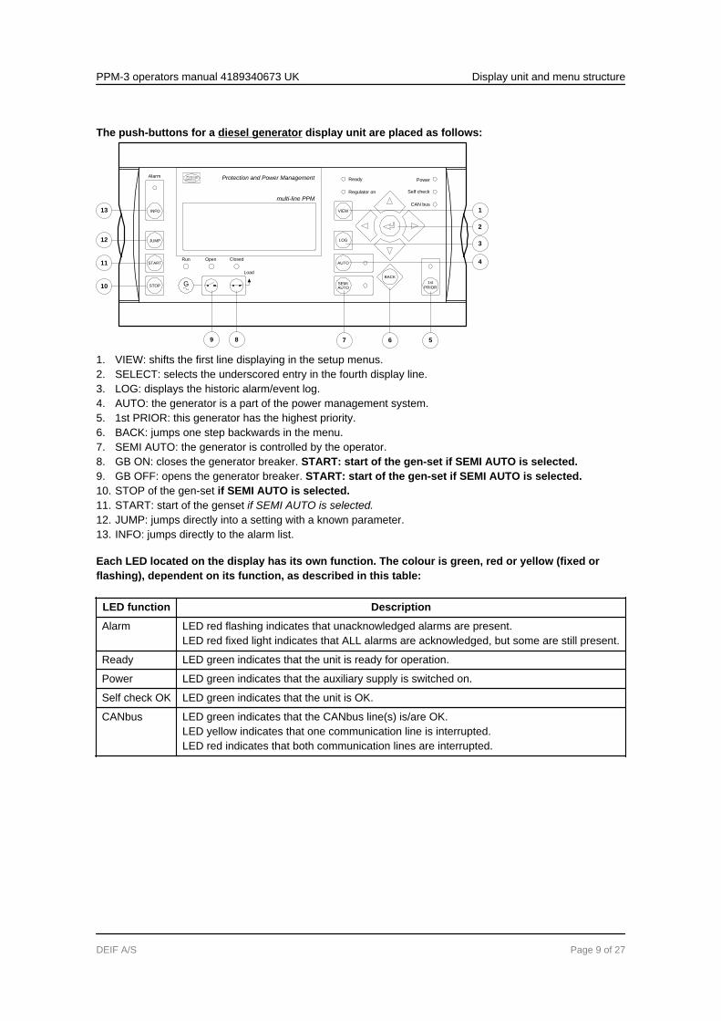
The push-buttons for a diesel generator display unit are placed as follows:
Protection and Power Management
multi-line PPM
Self check
CAN bus
Ready
Regulator on
JUMP
START
INFO
STOP
Alarm
VIEW
LOG
AUTO
AUTOSEMI 1st
PRIOR
BACK
G
Load
ClosedOpenRun
Power
13
12
11
10
9 8 56
2
7
4
3
1
1. VIEW: shifts the first line displaying in the setup menus.2. SELECT: selects the underscored entry in the fourth display line.3. LOG: displays the historic alarm/event log.4. AUTO: the generator is a part of the power management system.5. 1st PRIOR: this generator has the highest priority.6. BACK: jumps one step backwards in the menu.7. SEMI AUTO: the generator is controlled by the operator.8. GB ON: closes the generator breaker. START: start of the gen-set if SEMI AUTO is selected.9. GB OFF: opens the generator breaker. START: start of the gen-set if SEMI AUTO is selected.10. STOP of the gen-set if SEMI AUTO is selected.11. START: start of the genset if SEMI AUTO is selected.12. JUMP: jumps directly into a setting with a known parameter.13. INFO: jumps directly to the alarm list.
Each LED located on the display has its own function. The colour is green, red or yellow (fixed orflashing), dependent on its function, as described in this table:
LED function Description
Alarm LED red flashing indicates that unacknowledged alarms are present.LED red fixed light indicates that ALL alarms are acknowledged, but some are still present.
Ready LED green indicates that the unit is ready for operation.
Power LED green indicates that the auxiliary supply is switched on.
Self check OK LED green indicates that the unit is OK.
CANbus LED green indicates that the CANbus line(s) is/are OK.LED yellow indicates that one communication line is interrupted.LED red indicates that both communication lines are interrupted.
PPM-3 operators manual 4189340673 UK Display unit and menu structure
DEIF A/S Page 9 of 27
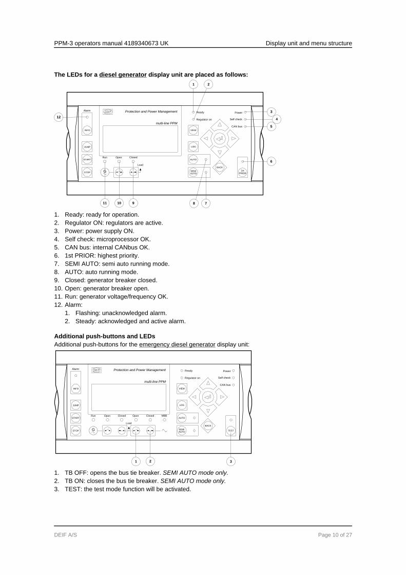
The LEDs for a diesel generator display unit are placed as follows:
12
10 9 7
4
8
6
5
3
11
1 2
Protection and Power Management
multi-line PPM
Self check
CAN bus
Ready
Regulator on
JUMP
START
INFO
STOP
Alarm
VIEW
LOG
AUTO
AUTOSEMI 1st
PRIOR
BACK
G
Load
ClosedOpenRun
Power
1. Ready: ready for operation.2. Regulator ON: regulators are active.3. Power: power supply ON.4. Self check: microprocessor OK.5. CAN bus: internal CANbus OK.6. 1st PRIOR: highest priority.7. SEMI AUTO: semi auto running mode.8. AUTO: auto running mode.9. Closed: generator breaker closed.10. Open: generator breaker open.11. Run: generator voltage/frequency OK.12. Alarm:
1. Flashing: unacknowledged alarm.2. Steady: acknowledged and active alarm.
Additional push-buttons and LEDsAdditional push-buttons for the emergency diesel generator display unit:
Protection and Power Management
multi-line PPM
Self check
CAN bus
Ready
Regulator on
JUMP
START
INFO
STOP
Alarm
VIEW
LOG
AUTO
AUTOSEMI
TEST
BACK
G
Load
ClosedOpen Open Closed MBBRun
Power
1 2 3
1. TB OFF: opens the bus tie breaker. SEMI AUTO mode only.2. TB ON: closes the bus tie breaker. SEMI AUTO mode only.3. TEST: the test mode function will be activated.
PPM-3 operators manual 4189340673 UK Display unit and menu structure
DEIF A/S Page 10 of 27
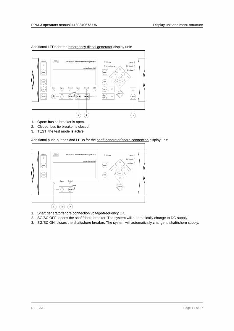
Additional LEDs for the emergency diesel generator display unit:
Protection and Power Management
multi-line PPM
Self check
CAN bus
Ready
Regulator on
JUMP
START
INFO
STOP
Alarm
VIEW
LOG
AUTO
AUTOSEMI
TEST
BACK
G
Load
ClosedOpen Open Closed MBBRun
Power
1 2 3
1. Open: bus tie breaker is open.2. Clsoed: bus tie breaker is closed.3. TEST: the test mode is active.
Additional push-buttons and LEDs for the shaft generator/shore connection display unit:
Protection and Power Management
multi-line PPM
Self check
CAN bus
Ready
JUMP
INFO
Alarm
VIEW
LOG
BACK
ClosedOpen
Power
Load
1 2 3
1. Shaft generator/shore connection voltage/frequency OK.2. SG/SC OFF: opens the shaft/shore breaker. The system will automatically change to DG supply.3. SG/SC ON: closes the shaft/shore breaker. The system will automatically change to shaft/shore supply.
PPM-3 operators manual 4189340673 UK Display unit and menu structure
DEIF A/S Page 11 of 27
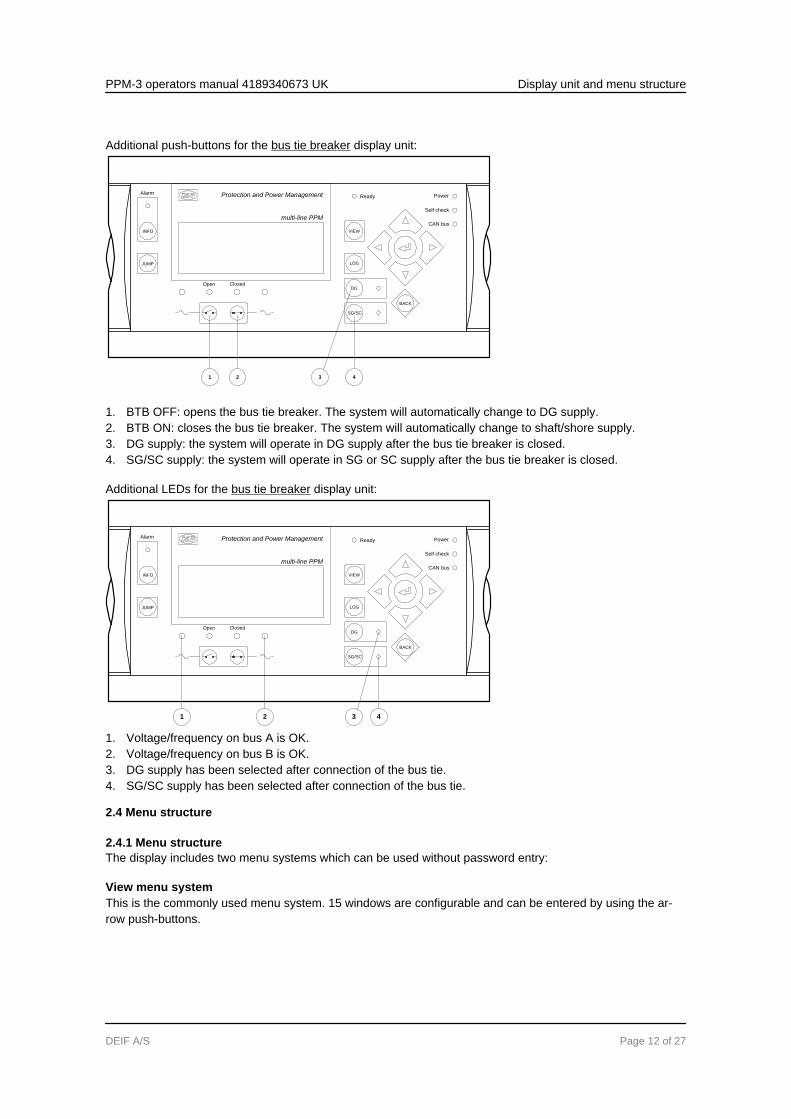
Additional push-buttons for the bus tie breaker display unit:
Protection and Power Management
multi-line PPM
Self check
CAN bus
Ready
JUMP
INFO
Alarm
VIEW
LOG
DG
SG/SC
BACK
ClosedOpen
Power
1 2 43
1. BTB OFF: opens the bus tie breaker. The system will automatically change to DG supply.2. BTB ON: closes the bus tie breaker. The system will automatically change to shaft/shore supply.3. DG supply: the system will operate in DG supply after the bus tie breaker is closed.4. SG/SC supply: the system will operate in SG or SC supply after the bus tie breaker is closed.
Additional LEDs for the bus tie breaker display unit:
Protection and Power Management
multi-line PPM
Self check
CAN bus
Ready
JUMP
INFO
Alarm
VIEW
LOG
DG
SG/SC
BACK
ClosedOpen
Power
1 2 43
1. Voltage/frequency on bus A is OK.2. Voltage/frequency on bus B is OK.3. DG supply has been selected after connection of the bus tie.4. SG/SC supply has been selected after connection of the bus tie.
2.4 Menu structure
2.4.1 Menu structureThe display includes two menu systems which can be used without password entry:
View menu systemThis is the commonly used menu system. 15 windows are configurable and can be entered by using the ar-row push-buttons.
PPM-3 operators manual 4189340673 UK Display unit and menu structure
DEIF A/S Page 12 of 27
Setup menu systemThis menu system is used for setting up the unit, and if the operator needs detailed information that is notavailable in the view menu system.Changing of parameter settings is password-protected.
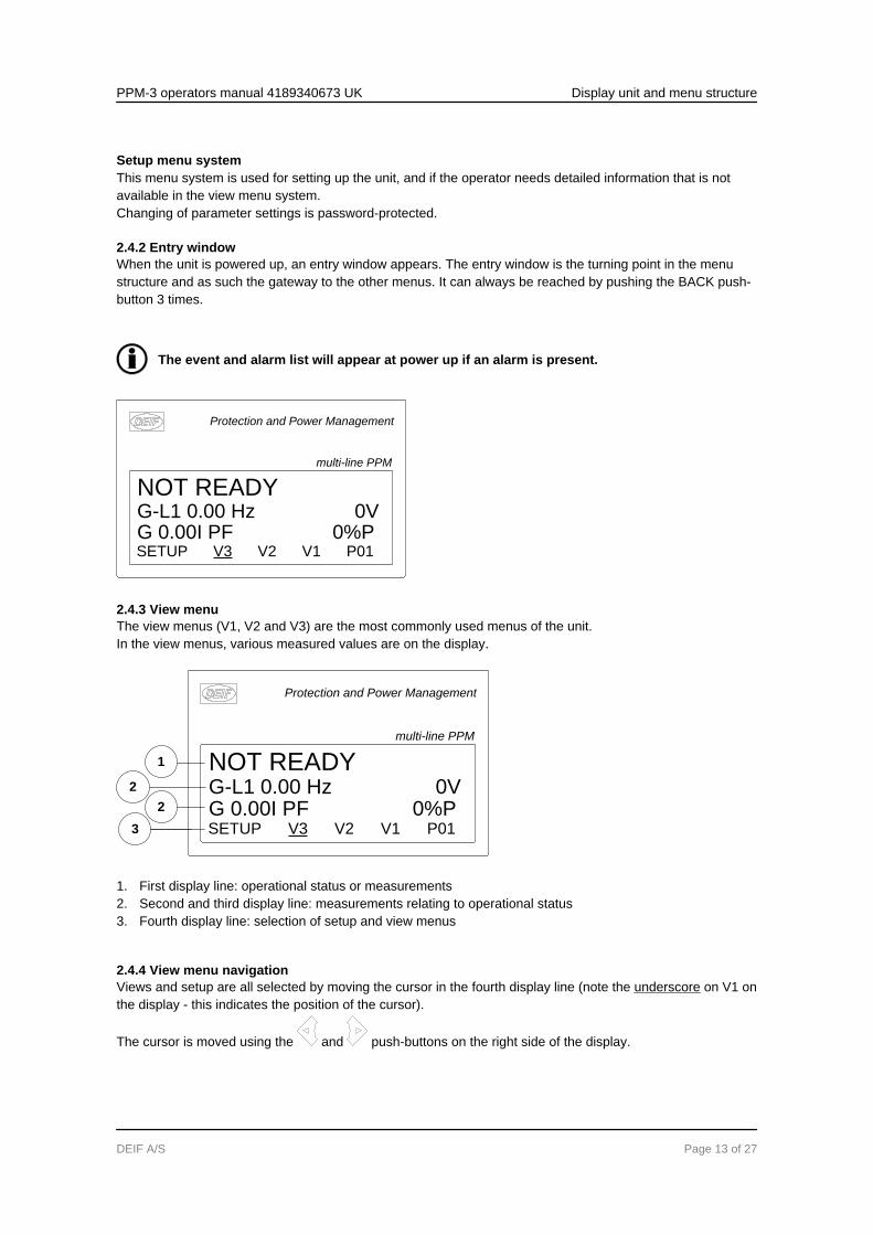
2.4.2 Entry windowWhen the unit is powered up, an entry window appears. The entry window is the turning point in the menustructure and as such the gateway to the other menus. It can always be reached by pushing the BACK push-button 3 times.
The event and alarm list will appear at power up if an alarm is present.
Protection and Power Management
multi-line PPM
NOT READYG-L1 0.00 Hz 0VG 0.00I PF 0%PSETUP V3 V2 V1 P01
2.4.3 View menuThe view menus (V1, V2 and V3) are the most commonly used menus of the unit.In the view menus, various measured values are on the display.
1
2
2
3
Protection and Power Management
multi-line PPM
NOT READYG-L1 0.00 Hz 0VG 0.00I PF 0%PSETUP V3 V2 V1 P01
1. First display line: operational status or measurements2. Second and third display line: measurements relating to operational status3. Fourth display line: selection of setup and view menus
2.4.4 View menu navigationViews and setup are all selected by moving the cursor in the fourth display line (note the underscore on V1 onthe display - this indicates the position of the cursor).
The cursor is moved using the and push-buttons on the right side of the display.
PPM-3 operators manual 4189340673 UK Display unit and menu structure
DEIF A/S Page 13 of 27

2.4.5 View window 1 (V1)
For detailed information about configuration, please see the Designer’s Reference Handbook.
V1 contains up to 20 different windows, which can be selected using the and push-buttons.
2.4.6 View window 2 (V2)
V2 is a copy of V1 and contains up to 20 different windows, which can be selected using the and push-buttons.
2.4.7 View window 3 (V3)The V3 display changes with running mode:The first display line indicates the running status of the unit. The messages shown in the table at the end ofthis chapter can be displayed.The second and third display lines display power consumption in kW or percentage. This is changed bypressing the arrow up or down.The fourth display line displays the selection line.
2.4.8 Setup menuThe setup menu system is used for parameter setup of the unit, but if the user needs detailed information,that is not available in the view menu system. In this way, this menu can be used for both daily use and setuppurposes. The menu is entered from the entry window by selecting the entry SETUP in the fourth display line.
1
2
3
4
Protection and Power Management
multi-line PPM
PROTECTION SETUPPROT CTRL I/O SYST
f-L1 50.00HZG 400 400 400V
1. First display line● Daily use: the first line is used to display generator and BUS values
2. Second display line● Daily use: various values can be displayed● Menu system: information about the selected channel number● Alarm/event list: the latest alarm/event is displayed
3. Third display line● Daily use: presents setting of the selected function, and if changes are made, the possible max. and
min. values for the setting● Setup menu: if changes are made, the possible max. and min. values for the setting are presented
4. Fourth display line● Daily use: entry selection for the setup menu. Press SELECT to select the underscored menu● Setup menu: sub-functions for the individual parameters, e.g. limit
PPM-3 operators manual 4189340673 UK Display unit and menu structure
DEIF A/S Page 14 of 27

Setup structure
2010-01-02 09.35.54SETUP V3 V2 V1
PPM V.3.00.0
PROT CTRL I/O SYST
G 400 400 400V
f-L1 50.00HZPROTECTION SETUP
f-L1 50.00HZPROTECTION SETUP
G 400 400 400V
PROT CTRL I/O SYST
f-L1 50.00HZPROTECTION SETUP
G 400 400 400V
PROT CTRL I/O SYST
f-L1 50.00HZPROTECTION SETUP
G 400 400 400V
PROT CTRL I/O SYST
SP DEL OA OB ENA FC
1000 G -P> 1Setpoint -5.0%
G 400 400 400V
SYNC REG
CONTROL SETUP
SYNCHRONISE SETUP
G 400 400 400V
BIN AIN OUT
INPUT/OUTPUT SETUP
BINARY INPUT SETUP
G 400 400 400V
GEN MAINS COMM PM
SYSTEM SETUP
GENERAL SETUP
G 400 400 400V
BACK
BACK BACK BACK BACK
Setup exampleThe following example illustrates how a specific setting is changed in the setup menu. In this case, Reversepower is the selected parameter.
First entry
Increase no.
Decrease no.
Increase setting
Decrease setting
Movea the cursor
YES
NO
PROT CTRL I/O SYST
G 400 400 400VG f-L1 50.00HZPROTECTION SETUP
G 400 400 400V
SP DEL OA OB ENA FC
1000 G -P> 1Setpoint -5.0%
G 400 400 400V
SP DEL OA OB ENA FC
1010 G -P> 2Setpoint -5.0%
ENTER
Enter passw. 2010G 400 400 400V
RESET SAVE
1001 G -P> 1-50.0 -5.0 0.0%
G 400 400 400V
BACK
BACK
PPM-3 operators manual 4189340673 UK Display unit and menu structure
DEIF A/S Page 15 of 27
2.5 Text in the display
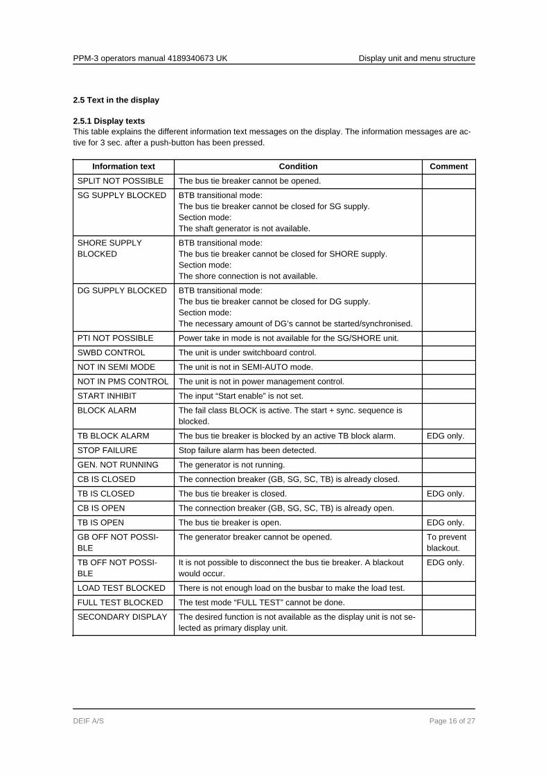
2.5.1 Display textsThis table explains the different information text messages on the display. The information messages are ac-tive for 3 sec. after a push-button has been pressed.
Information text Condition Comment
SPLIT NOT POSSIBLE The bus tie breaker cannot be opened.
SG SUPPLY BLOCKED BTB transitional mode:The bus tie breaker cannot be closed for SG supply.Section mode:The shaft generator is not available.
SHORE SUPPLYBLOCKED
BTB transitional mode:The bus tie breaker cannot be closed for SHORE supply.Section mode:The shore connection is not available.
DG SUPPLY BLOCKED BTB transitional mode:The bus tie breaker cannot be closed for DG supply.Section mode:The necessary amount of DG’s cannot be started/synchronised.
PTI NOT POSSIBLE Power take in mode is not available for the SG/SHORE unit.
SWBD CONTROL The unit is under switchboard control.
NOT IN SEMI MODE The unit is not in SEMI-AUTO mode.
NOT IN PMS CONTROL The unit is not in power management control.
START INHIBIT The input “Start enable” is not set.
BLOCK ALARM The fail class BLOCK is active. The start + sync. sequence isblocked.
TB BLOCK ALARM The bus tie breaker is blocked by an active TB block alarm. EDG only.
STOP FAILURE Stop failure alarm has been detected.
GEN. NOT RUNNING The generator is not running.
CB IS CLOSED The connection breaker (GB, SG, SC, TB) is already closed.
TB IS CLOSED The bus tie breaker is closed. EDG only.
CB IS OPEN The connection breaker (GB, SG, SC, TB) is already open.
TB IS OPEN The bus tie breaker is open. EDG only.
GB OFF NOT POSSI-BLE
The generator breaker cannot be opened. To preventblackout.
TB OFF NOT POSSI-BLE
It is not possible to disconnect the bus tie breaker. A blackoutwould occur.
EDG only.
LOAD TEST BLOCKED There is not enough load on the busbar to make the load test.
FULL TEST BLOCKED The test mode “FULL TEST” cannot be done.
SECONDARY DISPLAY The desired function is not available as the display unit is not se-lected as primary display unit.
PPM-3 operators manual 4189340673 UK Display unit and menu structure
DEIF A/S Page 16 of 27
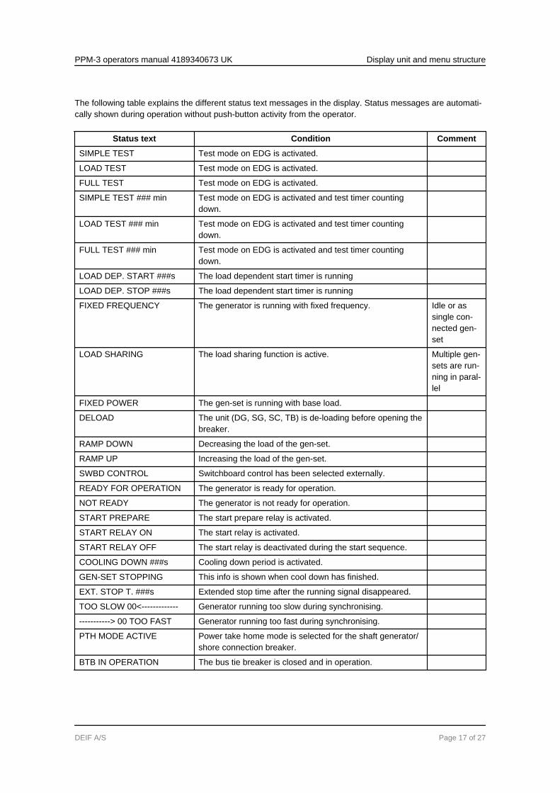
The following table explains the different status text messages in the display. Status messages are automati-cally shown during operation without push-button activity from the operator.
Status text Condition Comment
SIMPLE TEST Test mode on EDG is activated.
LOAD TEST Test mode on EDG is activated.
FULL TEST Test mode on EDG is activated.
SIMPLE TEST ### min Test mode on EDG is activated and test timer countingdown.
LOAD TEST ### min Test mode on EDG is activated and test timer countingdown.
FULL TEST ### min Test mode on EDG is activated and test timer countingdown.
LOAD DEP. START ###s The load dependent start timer is running
LOAD DEP. STOP ###s The load dependent start timer is running
FIXED FREQUENCY The generator is running with fixed frequency. Idle or assingle con-nected gen-set
LOAD SHARING The load sharing function is active. Multiple gen-sets are run-ning in paral-lel
FIXED POWER The gen-set is running with base load.
DELOAD The unit (DG, SG, SC, TB) is de-loading before opening thebreaker.
RAMP DOWN Decreasing the load of the gen-set.
RAMP UP Increasing the load of the gen-set.
SWBD CONTROL Switchboard control has been selected externally.
READY FOR OPERATION The generator is ready for operation.
NOT READY The generator is not ready for operation.
START PREPARE The start prepare relay is activated.
START RELAY ON The start relay is activated.
START RELAY OFF The start relay is deactivated during the start sequence.
COOLING DOWN ###s Cooling down period is activated.
GEN-SET STOPPING This info is shown when cool down has finished.
EXT. STOP T. ###s Extended stop time after the running signal disappeared.
TOO SLOW 00<------------- Generator running too slow during synchronising.
-----------> 00 TOO FAST Generator running too fast during synchronising.
PTH MODE ACTIVE Power take home mode is selected for the shaft generator/shore connection breaker.
BTB IN OPERATION The bus tie breaker is closed and in operation.
PPM-3 operators manual 4189340673 UK Display unit and menu structure
DEIF A/S Page 17 of 27

Status text Condition Comment
IN OPERATION The SG/SC breaker is closed and in operation.
FUEL OPTIMISATION The fuel optimisation function is active.
PROGRAMMING LAN-GUAGE
The language file is downloaded from the USW.
2.6 Mode overview
2.6.1 Overview of modesThe unit has three (EDG: four) different running modes and one switchboard (blocked) mode.
Mode Description
SEMI-AUTO
● The display push-buttons (START, STOP, GB ON, GB OFF) are active and can be used bythe operator.
● The reulators are also active, i.e. the speed control will bring the generator to nominalspeed upon start.
● When pushing a breaker button for closing, the DG will synchronise (if allowed) the breaker.
TEST(EDG)
● The unit will start the generator, carry out the test sequence (predefined time period) andstop the generator again. Subsequently, the generator will return to AUTO or SEMI-AUTOmode. The TB will remain closed, and the generator breaker will remain open. NOTE: Thetest running can be: Simple test: starting the gen-set without closing the TB GB. Load test:parallel to the BB and take load to a predefined value. Full test: transfer the load to the gen-set and open the TB.
AUTO ● The unit will be a part of the power management system.● The display control push-buttons (START, STOP, GB ON, GB OFF) are disabled.
SWBD ● Display push-buttons are disabled. The generator can only be controlled by using theswitchboard.
● The protection functions are still active.● The regulators are not active, i.e. speed (and voltage) control has to take place using binary
inputs for UP and DOWN control.
2.7 Mode selection
2.7.1 Selection of modeThe mode selection is carried out using the AUTO or SEMI push-buttons on the display. The SWBD mode ischosen when the binary input 23 (SWBD control) is activated.
The EDG test mode is activated by using the test push-button.
2.8 Password
2.8.1 Password levelsThe unit includes three password levels. All levels can be adjusted in the PC software.
PPM-3 operators manual 4189340673 UK Display unit and menu structure
DEIF A/S Page 18 of 27
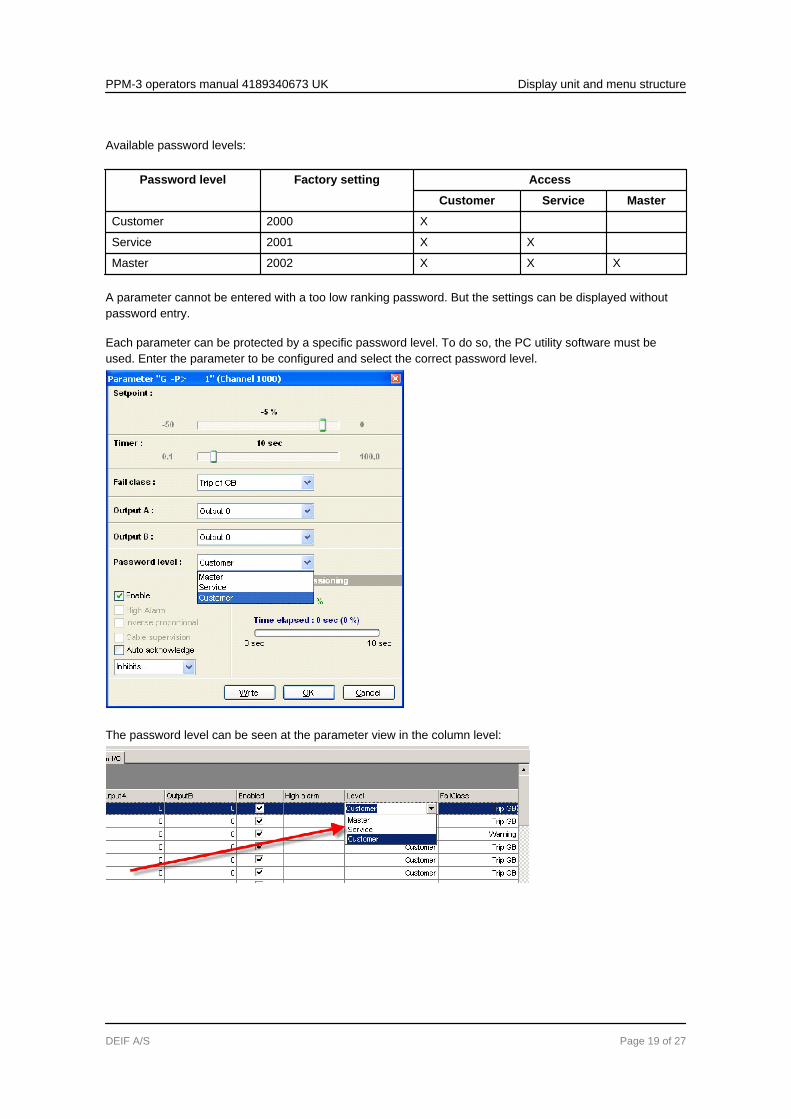
Available password levels:
Password level Factory setting Access
Customer Service Master
Customer 2000 X
Service 2001 X X
Master 2002 X X X
A parameter cannot be entered with a too low ranking password. But the settings can be displayed withoutpassword entry.
Each parameter can be protected by a specific password level. To do so, the PC utility software must beused. Enter the parameter to be configured and select the correct password level.
The password level can be seen at the parameter view in the column level:
PPM-3 operators manual 4189340673 UK Display unit and menu structure
DEIF A/S Page 19 of 27
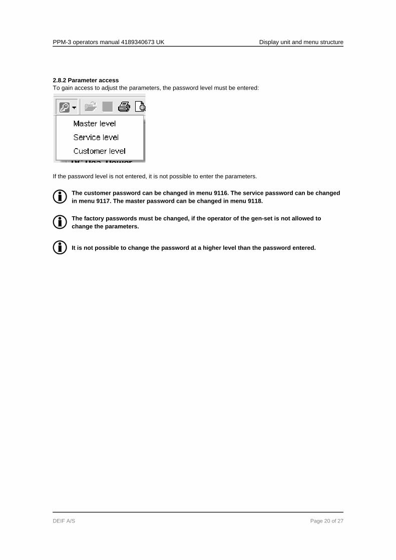
2.8.2 Parameter accessTo gain access to adjust the parameters, the password level must be entered:
If the password level is not entered, it is not possible to enter the parameters.
The customer password can be changed in menu 9116. The service password can be changedin menu 9117. The master password can be changed in menu 9118.
The factory passwords must be changed, if the operator of the gen-set is not allowed tochange the parameters.
It is not possible to change the password at a higher level than the password entered.
PPM-3 operators manual 4189340673 UK Display unit and menu structure
DEIF A/S Page 20 of 27
3. Alarm handling and log list3.1 Alarm handling
3.1.1 How to handle alarms
When an alarm occurs, the unit will automatically go to the alarm list for display of the alarm. This functioncan be disabled or enabled. For further explanation, please see the Designer’s Reference Handbook.
If reading of the alarms is not desired, use the BACK push-button to exit the alarm list.
If you decide to enter the alarm list later, use the INFO push-button to jump directly to the alarm list reading.
The alarm list contains both acknowledged and unacknowledged alarms provided that they are still active (i.e.the alarm condition is still present). Once an alarm is acknowledged and the condition has disappeared, thealarm will no longer be displayed in the alarm list.
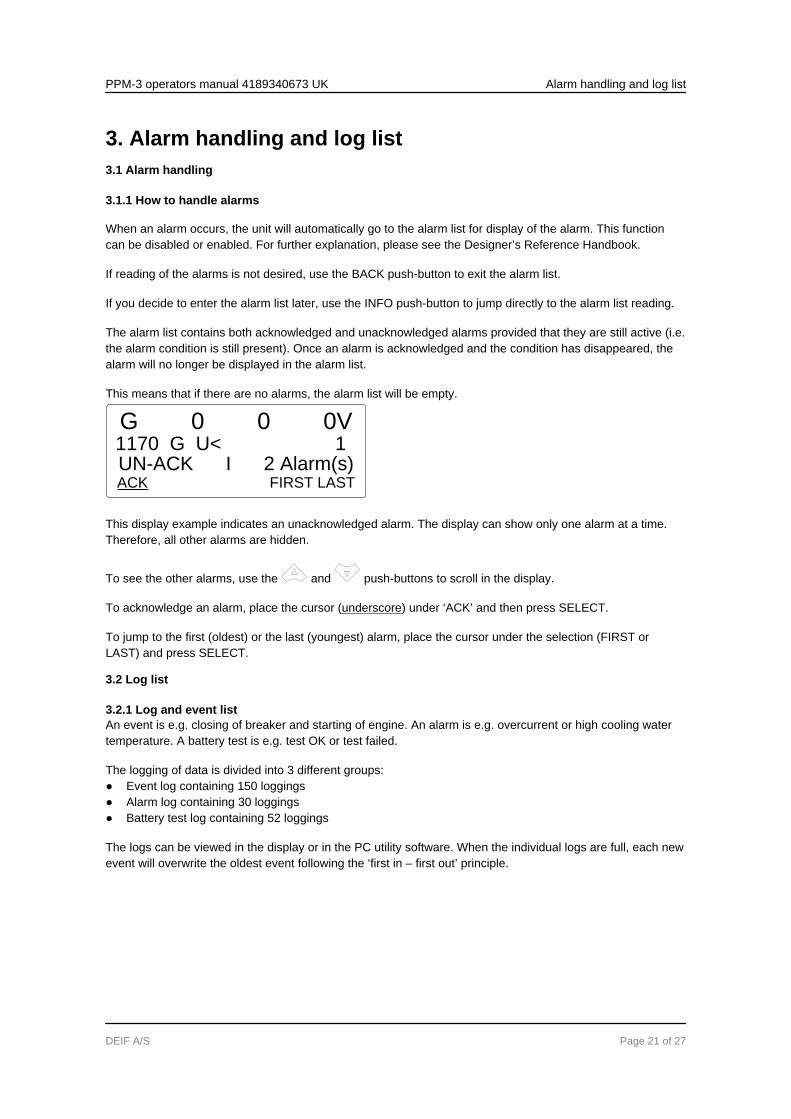
This means that if there are no alarms, the alarm list will be empty.
G 0 0 0V1170 G U< 1UN-ACK I 2 Alarm(s)ACK FIRST LAST
This display example indicates an unacknowledged alarm. The display can show only one alarm at a time.Therefore, all other alarms are hidden.
To see the other alarms, use the and push-buttons to scroll in the display.
To acknowledge an alarm, place the cursor (underscore) under ‘ACK’ and then press SELECT.
To jump to the first (oldest) or the last (youngest) alarm, place the cursor under the selection (FIRST orLAST) and press SELECT.
3.2 Log list
3.2.1 Log and event listAn event is e.g. closing of breaker and starting of engine. An alarm is e.g. overcurrent or high cooling watertemperature. A battery test is e.g. test OK or test failed.
The logging of data is divided into 3 different groups:● Event log containing 150 loggings● Alarm log containing 30 loggings● Battery test log containing 52 loggings
The logs can be viewed in the display or in the PC utility software. When the individual logs are full, each newevent will overwrite the oldest event following the ‘first in – first out’ principle.
PPM-3 operators manual 4189340673 UK Alarm handling and log list
DEIF A/S Page 21 of 27
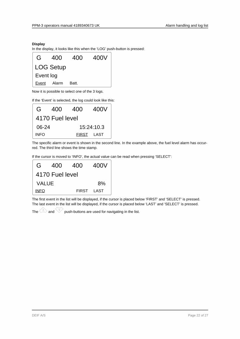
DisplayIn the display, it looks like this when the ‘LOG’ push-button is pressed:
Event Alarm Batt.
G 400 400 400V
LOG Setup
Event log
Now it is possible to select one of the 3 logs.
If the ‘Event’ is selected, the log could look like this:
4170 Fuel level
06-24 15:24:10.3
INFO FIRST LAST
G 400 400 400V
The specific alarm or event is shown in the second line. In the example above, the fuel level alarm has occur-red. The third line shows the time stamp.
If the cursor is moved to ‘INFO’, the actual value can be read when pressing ‘SELECT’:
4170 Fuel level
VALUE 8%
INFO FIRST LAST
G 400 400 400V
The first event in the list will be displayed, if the cursor is placed below ‘FIRST’ and ‘SELECT’ is pressed.The last event in the list will be displayed, if the cursor is placed below ‘LAST’ and ‘SELECT’ is pressed.
The and push-buttons are used for navigating in the list.
PPM-3 operators manual 4189340673 UK Alarm handling and log list
DEIF A/S Page 22 of 27

4. Service menu4.1 Service menu overview
4.1.1 Present operating conditionThe purpose of the service menu is to give information about the present operating condition of the gen-set.The service menu is entered using the ‘JUMP’ push-button and selecting menu 9120.Use the service menu for easy troubleshooting in connection with the event log.
Entry window
The entry shows the possible selections in the service menu.
ALARM IN OUT MISC
G 400 400 400V
9120 Service menu
ALARM
Available selections:
AlarmShows the alarm timer and the remaining time. The indicated remaining time is minimum remaining time. Thetimer will count downwards when the setpoint has been exceeded.
UP DOWN
G 400 400 400V
1010 Reverse power
Remaining time 10.0s
IN (digital input)Shows the status of the digital inputs.
UP DOWN
G 400 400 400V
Running
Input = ON
PPM-3 operators manual 4189340673 UK Service menu
DEIF A/S Page 23 of 27
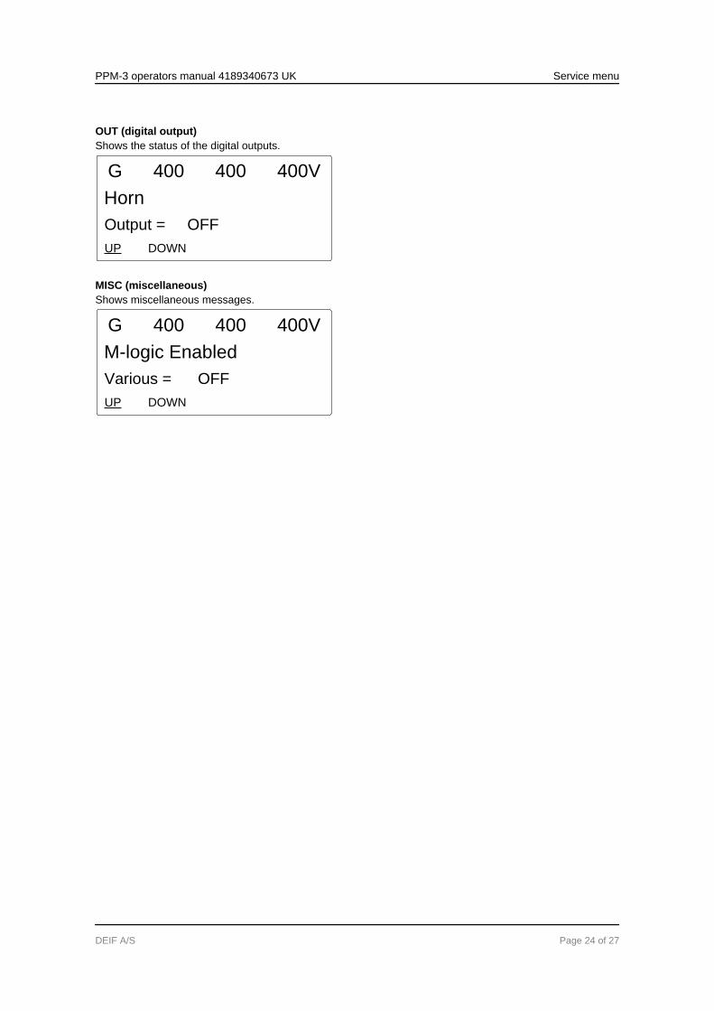
OUT (digital output)Shows the status of the digital outputs.
UP DOWN
G 400 400 400V
Horn
Output = OFF
MISC (miscellaneous)Shows miscellaneous messages.
UP DOWN
G 400 400 400V
M-logic Enabled
Various = OFF
PPM-3 operators manual 4189340673 UK Service menu
DEIF A/S Page 24 of 27
5. Parameter setup5.1 About parameter setup
The complete parameter list is presented in the separate document Parameter List, documentno. 4189340561.
This chapter deals with the procedure to be followed when the parameters of the unit are set up from theinitial point of finding the individual parameter description in this handbook to the actual setup. By use of vari-ous illustrations, the following will guide the user through the whole procedure for parameter setup step bystep.
5.2 Finding the selected parameter
5.2.1 How to find the correct parameterThe first step in the parameter setup is finding the correct parameter descriptions. All parameter descriptionsin the document ‘Parameter list’ are intended for reference purposes. The descriptions are structured accord-ing to their parameter titles and the main parameter group to which they belong.
5.3 Parameter descriptions
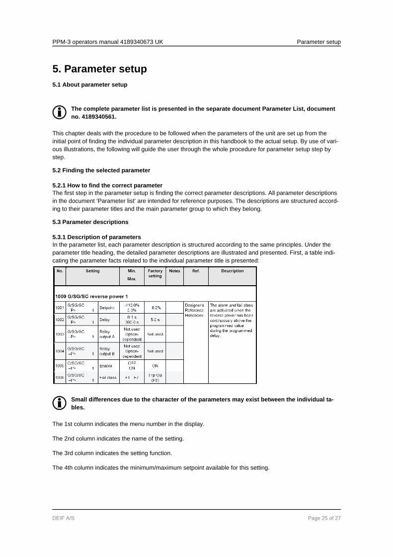
5.3.1 Description of parametersIn the parameter list, each parameter description is structured according to the same principles. Under theparameter title heading, the detailed parameter descriptions are illustrated and presented. First, a table indi-cating the parameter facts related to the individual parameter title is presented:
Small differences due to the character of the parameters may exist between the individual ta-bles.
The 1st column indicates the menu number in the display.
The 2nd column indicates the name of the setting.
The 3rd column indicates the setting function.
The 4th column indicates the minimum/maximum setpoint available for this setting.
PPM-3 operators manual 4189340673 UK Parameter setup
DEIF A/S Page 25 of 27

The 5th column indicates the default setpoint of the unit from the factory.
The 6th column is used for user information notes.
The 7th column gives references for additional information.
The 8th column is describing the function.
5.4 Setup
5.4.1 Parameter setupAt this point of the process, the specific parameter description will have been located. Now, follow the menustructure presented earlier in this manual in order to set up the individual parameters. (In this overall example,we have chosen to change the setpoint of the parameter 1000 G -P>).
Step 1: Enter the ‘setup’ menu via SETUP in the fourth display line in the entry window.Step 2: Enter the ‘protection’ menu via PROT in the fourth display line in the setup menu.
Step 3: Use the and push-buttons to locate the selected parameter.Step 4: Enter the ‘setpoint’ menu via SP in the fourth display line.Step 5: Enter password to change the setpoint.
Step 6: Use the and push-buttons to increase/decrease the setpoint setting.Step 7: Move the ’underscore’ to save and press SEL, the new setpoint setting has now been saved.
PPM-3 operators manual 4189340673 UK Parameter setup
DEIF A/S Page 26 of 27
6. Failure mode and effect analysis6.1 Troubleshooting
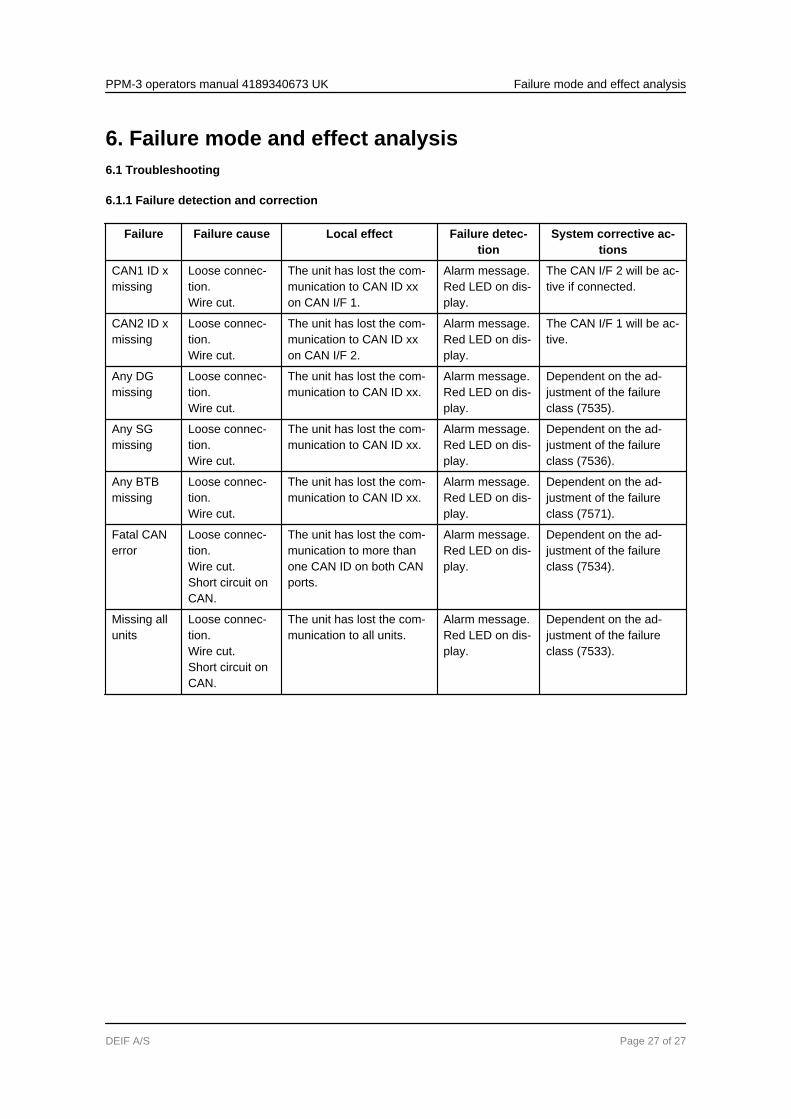
6.1.1 Failure detection and correction
Failure Failure cause Local effect Failure detec-tion
System corrective ac-tions
CAN1 ID xmissing
Loose connec-tion.Wire cut.
The unit has lost the com-munication to CAN ID xxon CAN I/F 1.
Alarm message.Red LED on dis-play.
The CAN I/F 2 will be ac-tive if connected.
CAN2 ID xmissing
Loose connec-tion.Wire cut.
The unit has lost the com-munication to CAN ID xxon CAN I/F 2.
Alarm message.Red LED on dis-play.
The CAN I/F 1 will be ac-tive.
Any DGmissing
Loose connec-tion.Wire cut.
The unit has lost the com-munication to CAN ID xx.
Alarm message.Red LED on dis-play.
Dependent on the ad-justment of the failureclass (7535).
Any SGmissing
Loose connec-tion.Wire cut.
The unit has lost the com-munication to CAN ID xx.
Alarm message.Red LED on dis-play.
Dependent on the ad-justment of the failureclass (7536).
Any BTBmissing
Loose connec-tion.Wire cut.
The unit has lost the com-munication to CAN ID xx.
Alarm message.Red LED on dis-play.
Dependent on the ad-justment of the failureclass (7571).
Fatal CANerror
Loose connec-tion.Wire cut.Short circuit onCAN.
The unit has lost the com-munication to more thanone CAN ID on both CANports.
Alarm message.Red LED on dis-play.
Dependent on the ad-justment of the failureclass (7534).
Missing allunits
Loose connec-tion.Wire cut.Short circuit onCAN.
The unit has lost the com-munication to all units.
Alarm message.Red LED on dis-play.
Dependent on the ad-justment of the failureclass (7533).
PPM-3 operators manual 4189340673 UK Failure mode and effect analysis
DEIF A/S Page 27 of 27


![DDS C ,bc ]^ - NEDO · DDS ˘ˇˆ ... DSBL 3.70 ppm DSBL 1.23 ppm BC 100.00 ppm BC 33.33 ppm BC 11.11 ppm BC 3.70 ppm BC 1.23 ppm DMCBL 100.00 ppm DMCBL 33.33 ppm DMCBL 11.11 ppm](https://img.pdfslide.tips/doc/110x75/5ad6c02a7f8b9a6d708e8ad8/dds-c-bc-dsbl-370-ppm-dsbl-123-ppm-bc-10000-ppm-bc-3333-ppm.jpg)