Embed Size (px)
Citation preview

PPM Protection and Power Management DATA SHEET
Power Management • Multiple master system • Redundant internal communication • Load-dependent start/stop • Fuel optimisation logic • Programmable start priority • Heavy consumer control • Blackout start sequence • Trip of non-essential load groups
Protection (ANSI) • 5 x Overload (32) • 2 x Reverse power (32) • 6 x Overcurrent (50/51) • Voltage-dependent overcurrent (92) • 3 x Over/undervoltage (27, 59) • 3 x Over/underfrequency (81) • Current/voltage unbalance (60) • Loss of excitation/overexcitation (40)
M-logic (Micro PLC) • Simple logic configuration tool • Selectable input/output events
Document no.: 4921240337A SW version 3.00.0 or later
Display • Push-buttons for start/stop and breaker • Status texts • Information messages • Alarm indication • One-touch sequences • Prepared for additional remote displays
General • USB interface to PC • Free PC utility software for commissioning • Mini SCADA in PC utility software • Programmable parameter, timer and alarms • User-configurable texts
Engine control and protection • Run and stop coil • GOV and AVR control • 3 x alarm inputs with wire break supervision
Data sheet Protection and Power Management
DEIF A/S Page 2 of 12
Application The Protection and Power Management (PPM) is a standard system for marine applications with microprocessor-based control units containing all necessary functions for protection and control of diesel generators, shaft generators, shore connections and bus tie breakers. It contains all necessary 3-phase measuring circuits and all values and alarms are presented on the LCD display. The PPM is a compact all-in-one unit designed for the following applications:
• Multiple gen-sets • Split busbars with independent section control • Ring bus connection • Shaft generator and shore connection control • Bus tie breaker control • Emergency generator control
Operation modes:
• Load sharing between diesel generators • Fixed power (diesel generator) • Load transfer between shaft- and diesel
generator • Load transfer between shore connection and
diesel generator • Split busbar
The display is separate and can be installed directly on the main unit or in the front of the switchboard door (requires option J1 - display cable). Additional displays can be installed within 200m. The PPM is supplied with an engine interface I/O card with separate power supply and processor. The card is equipped with the following I/Os:
Plant operation The plant operation depends on the plant configuration, i.e. if there are shaft generator(s), bus tie breaker(s), synchronisable shore connection(s) and/or an emergency diesel generator involved. Switching between different operation modes is done with push-buttons on the display. Unit control modes AUTO: Auto control means that the plant is controlled
automatically by PPM and gen-set starting and stopping is based on power demand (when in DG supply operation). Upon operator command, switching between different operation modes is done automatically.
SEMI: Semi-auto control is an operator dependent
auto mode. This means that gen-set start/stop, synchronisation and opening of the breaker is carried out by PPM on operator command only. A diesel generator unit connected in semi-auto will not be a part of the load- dependent start/stop function.
SWBD: Switchboard control means that PPM is
disabled totally with regards to start/stop/synchronising and load sharing. The protection functions remain active.
Setup Setup is easily done via a menu structure in the display (password-protected) or via the USB PC connection and the Multi-line 2 Windows®-based PC utility software. The PC utility software can be downloaded free of charge from . The utility software offers additional features such as monitoring of all relevant information during commissioning, saving and downloading of settings and downloading of software updates. Options In order to perfectly match the product solution to specific applications, the functionality of the PPM can be equipped with a number of available options. The options selected by the customer will be integrated in the standard PPM, hereby securing the same user interface unaffected by whether the application needs a highly complex or a more basic gen-set controller. Please refer to pages 7 and 8 for the options available. Unit definitions PPM DG: Diesel generator controller. PPM SG: Shaft generator controller. PPM SC: Shore connection controller. PPM BTB: Bus tie breaker controller. PPM EDG: Emergency diesel generator controller. M-logic (Micro PLC) This configuration tool is part of the PC utility software which is free of charge. With this tool, it is possible to customise the application to your needs. It is possible to dedicate specific functions or logical conditions to different inputs and outputs.
In-/outputs Available 4-20mA Digital inputs PT100 PT1000 VDO
Multi-inputs:
0-40V DC
3 (3)
Digital inputs 7 (4) RPM (MPU) 1 Relays 4 CANbus comm. 2
The number in parenthesis indicates the number of user configurable in-/outputs.
One of the two CAN communications (1) is used for internal communication. CAN 2 is for communication options or redundant internal CAN.
Data sheet Protection and Power Management
DEIF A/S Page 3 of 12
Power management
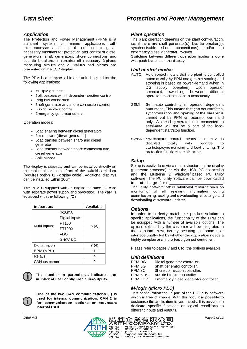
Description The PPM is a power management system able to handle applications with up to
• 8 bus tie breakers (BTB) • 16 diesel generators (DG) • 1 emergency generator (EDG) • 2 shaft generators (SHAFT) • 2 shore connections (SHORE)
The basic functions are:
• All breakers can be synchronised by choice • Load-dependent start/stop operation • Priority selection of gen-sets • Redundant communication between the
controllers • Plant divided into sections for individual
functionality • Load transfer • Heavy consumer management • Multi-master system
In a multi-master system, all vital data is broadcasted from all units to all units, giving all units knowledge of their own position in the application. This philosophy makes the application immune to a failing master controller. Application The plant operational modes supported by the power management options are:
• Diesel generator operation • Shaft generator operation • Shore connection operation • Split busbar(s) operation • Emergency/harbour generator operation
The plant operational modes are configurable and it is possible to change them on the fly, dependent on the actual or desired situation. The plant can be divided into sections by several bus tie breakers, making it possible to run different operation modes in each section.
Configuration The setup of the application is easily configured using a computer and the DEIF PC utility software.
Your PC tool visualises it - the PPM realises it. Heavy consumer management The heavy consumer management functions are available to ensure sufficient power capacity to handle the load either in terms of number of gen-sets or by soft starting the load. Available power can be reserved for heavy consumers with variable load e.g. bow thrusters. If a certain level of available power on the busbar is required to connect a heavy consumer, a function is available for starting additional generators. Furthermore, relays can be configured to activate when a specific level of available power is reached. Load-dependent operation The load-dependent starting and stopping of the gen-sets are based on a power available calculation. The next generator will start when the available power decreases below the adjustable setpoint. It will stop when too much power is available. Priority selection The start/stop priority of the diesel generators can be set in different ways:
• Manual selection with the 1st PRIOR push-button on each diesel generator unit.
• Running hours. • Fuel optimising calculating the best
combination of generator kW size and the plant load. Works with up to 16 gen-sets.
Redundant CANbus In systems requiring extra operation reliability, redundant CANbus communication lines can be used to provide back-up.

Data sheet Protection and Power Management
DEIF A/S Page 4 of 12
Display layouts Diesel generator display Shaft generator/Shore connection display Bus tie breaker display Emergency diesel generator display Additional operator panel display (AOP)
Data sheet Protection and Power Management
DEIF A/S Page 5 of 12
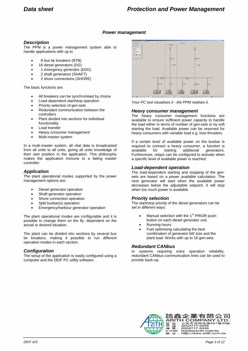
Power management applications
1. DG operation
Up to 16 generators.
2. Shaft generator/Shore connection
For shore connection, the shaft generator position is used for the shore connection.
3. One or two shaft generators/shore connections with split busbars
The bus tie breaker is selectable depending on applicational needs.

Data sheet Protection and Power Management
DEIF A/S Page 6 of 12
Power management applications
4. Multiple bus tie breakers
The bus tie breakers are selectable depending on applicational needs.
5. Emergency generator
The emergency generator can be combined with any other plant type.

Data sheet Protection and Power Management
DEIF A/S Page 7 of 12
Available options
Option Description Slot
no. Option type
Note
B Generator/busbar protection package B1 Over- and undervoltage (generator and busbar) (27/59)
Over- and underfrequency (generator and busbar) (81) Voltage unbalance (busbar) (60)
Software Included as standard
C Generator add-on protection package C1 Over- and undervoltage (27/59)
Over- and underfrequency (81) Overload (32) Current unbalance (46) Voltage unbalance (60) Reactive power import (excitation loss) (40) Reactive power export (overexcitation) (40) Voltage dependent overcurrent (92)
Software Included as standard
D Voltage/VAr/PF control Not available for PPM SG/SC and PPM BTB
D1 Constant voltage control (stand-alone) Constant reactive power control (parallel with mains) Constant power factor control (parallel with mains) Reactive load sharing (island paralleling with other generators)
Software Not with EF2
E and F Analogue controller and transducer outputs E1 2 x +/-25mA (GOV/AVR or transducer)
4 Hardware Not with E2, EF2, EF4 or EF5
AVR output requires D1 E2 2 x 0(4)...20mA (GOV/AVR or transducer) 4 Hardware Not with E1, EF2, EF4 or EF5
AVR output requires D1 EF2 1 x +/-25mA (GOV/AVR or transducer)
1 x 0(4)...20mA (GOV/AVR or transducer) 4 Hardware Not with E1, E2, EF4 or EF5
AVR output requires D1 EF4 1 x +/-25mA (GOV/AVR or transducer)
2 x relay outputs (GOV/AVR or configurable) 4 Hardware Not with E1, E2, EF2 or EF5
AVR output requires D1 EF5 1 x PWM (Puls Width Modulated) output for CAT GOV
+/-20mA for AVR. 2 x relay outputs (GOV/AVR or configurable)
4 Hardware Not with E1, E2, EF2 or EF4 AVR output requires D1
F1 2 x 0(4)...20mA (transducer) 6 Hardware Not with M13.6, M14.6 or M15.6 G Load sharing
G3 Load sharing with analogue lines Software G5 Power management, 16 gen-sets, 8 bus tie breakers, 2 shaft
generators, 2 shore connections, 1 emergency-/harbour generator
Software Included as standard
H Serial communication H2 Modbus RTU (RS485) 2 Hardware Not with H3, H8.2 H3 Profibus DP 2 Hardware Not with H2, H8.2 H5 CANbus:
MTU (ADEC and MDEC) and all J1939 engine comm. in option H7
8 Hardware Not with H7, H8.8, M13.8, M14.8 or M15.8. Not available for PPM SG/SC and PPM BTB.
H7 CANbus (J1939): Caterpillar Perkins Cummins CM850/570 Scania (EMS) Detroit Diesel (DDEC) Scania (EMS S6) Deutz (EMR) Volvo Penta (EMS Iveco (NEF/CURSOR) Volvo (EMS2) John Deere (JDEC)
7 Software Not with H5 or redundant PMS CANbus.Not available for PPM SG/SC and PPM BTB.
H8.X External I/O modules 2, 8 Hardware H8.2: Not with H2, H3, H8.8 H8.8: Not with H5, H8.2, M13.8, M14.8 or M15.8
(ANSI# as per IEEE Std. C37.2-1996 (R2001) in parenthesis)
Options E1, E2, EF2, EF4 and EF5 are used for GOV/AVR control. 4 relays are used as standard in the PPM for GOV/AVR control. If selected, these options will replace the 4 relays.

Data sheet Protection and Power Management
DEIF A/S Page 8 of 12
Option Description Slot
no. Option type
Note
J Cables J1 Display cable with plugs, 3 m. UL94 (V1) approved Other Included as standard J2 Display cable with plugs, 6 m. UL94 (V1) approved Other J4 PC cable for option N-programming UL94 (Ethernet cable
crossed), 3 m. UL94 (V1) Listed. Other
J6 PC cable for utility software (USB) 1 m. UL94 (V1) approved Other J7 PC cable for utility software (USB) 3 m. UL94 (V1) approved Other
K Documentation K1 Designer’s Reference Handbook (hard copy) Other K2 CD-ROM with complete documentation Other
L Display gasket for IP54 Other Standard is IP52 M Binary and analogue I/Os
M12 13 binary inputs, 4 relay outputs, configurable 3 Hardware Included as standard M13.X 7 binary inputs, configurable 6, 8 Hardware M13.6: Not with F1, M14.6 or M15.6
M13.8: Not with H5, H8.8, M14.8 or M15.8
M14.X 4 relay outputs, configurable 4, 6, 8 Hardware M14.4: (standard) Not with E1, E2, EF2 or EF4 M14.6: Not with F1, M13.6 or M15.6 M14.8: Not with H5, H8.8, M13.8 or M15.8
M15.X 4 analogue inputs, configurable, 4...20mA 6, 8 Hardware M15.6: Not with F1, M13.6, M14.6 or M15.8 M15.8: Not with H5, H8.8, M13.8, M14.8 or M15.6
N Ethernet TCP/IP communication N Ethernet TCP/IP Modbus comm. and alarms via SMS or e-mail Hardware/
software
Q Measurement accuracy Q1 Verified class 0,5 Other
X Display One Display per PPM unit is included as standard
X2 Additional standard display. CANbus comm. Other Two X2 options can be ordered for each PPM unit
X3 Additional operator panel (AOP-1): 16 configurable LEDs and 8 configurable push-buttons
Other Max. one AOP-1 for each display unit
X4 Additional operator panel (AOP-2): 16 configurable LEDs, 8 configurable buttons and 1 status relay. CANbus comm.
Other Five X4 options can be ordered for each PPM unit
Please notice that not all options can be selected for the same unit. Please refer to page 9 in this data sheet for further information about the location of the options in the unit.

Data sheet Protection and Power Management
DEIF A/S Page 9 of 12
Hardware overview
Besides the hardware options shown on this page, it is possible to select the software options mentioned in the chapter ‘Available options’.
Eth
erne
t
7877
7675
7473
9697
9594
9291
9093
8988
8785
8683
8482
8180
79
7271
6970
6867
6566
6263
5960
6158
5657
5553
5464
5251
5049
4746
4443
4548
4140
3837
3942
US
B M
emor
yS
ervi
ce p
ort
Dis
play
Eth
erne
tP
MS
CA
NE
ngin
e C
AN
US
B
Pow
erS
elf c
heck
ok
Ala
rm in
hibi
t
N: TCP/IP Modbus comm. and alarm via SMS or email
G3: Active power load sharing Reactive power load sharing (requires option D1)
13 x digital inputs 4 x relay outputs (standard)
8-36V DC supply, 11W 1 x status output relay 5 x relay outputs 2 x pulse outputs (kWh, kVArh) 5 x digital inputs
3 x generator voltage 3 x generator current 3 x busbar/mains voltage
M15.6: 4 x 4…20mA inputs
M13.6: 7 x digital inputs
F1: 2 x 0(4)…20mA out, transducer
M14.6: 4 x relay outputs
E1: 2 x +/-20mA out
EF2: 1 x +/-20mA out 1 x 0(4)…20mA out
EF4: 1 x +/-20mA out 2 x relay
M14.4: 4 x relay (standard)
E2: 2 x 0(4)…20mA out
Slot #4, term. 65-72 Governor, AVR, in-/outputs
Slot #1, term. 1-28 Power supply (standard)
Slot #3, term. 37-64 In-/outputs/load sharing
Slot #6, term. 90-97 In-/outputs
Ethernet
Slot #8, term. 126-133 Engine comm., in-/outputs
Slot #7, term. 98-125 Engine I/F (std.)
Slot #5, term. 73-89 AC measuring (standard)
Display connection PC programming connection
LED I/F
8-36V DC supply, 5W 1 x magnetic pick-up (MPU) 3 x multi-inputs 7 x digital inputs 4 x relay outputs
G5: Power management (standard)
H7: J1939
There can only be one hardware option in each slot. It is e.g. not possible to select option H2 and option H3 at the same time, because both options require a PCB in slot #2.
Slot #2, term. 29-36 Communication
H2: Modbus RTU (RS485)
H3: Profibus DP
H8.2: Ext. I/O modules
H5: MTU (MDEC) + J1939 (option H7)
M14.8: 4 x relay outputs
M15.8: 4 x 4-20 mA input
H8.8: Ext. I/O modules
M13.8: 7 x digital inputs
EF5: 1 x PWM governor output 1 x +/-20mA out for AVR 2 x relay

Data sheet Protection and Power Management
DEIF A/S Page 10 of 12
Technical specifications
Accuracy: Class 1.0
Positive, negative and zero sequence alarms: Class 1 within 5% voltage unbalance
Class 1.0 for negative sequence current
Fast overcurrent: 3% of 350%*In
Analogue outputs: Class 1.0 according to total range
Option EF4: Class 4.0 according to total range
To EN60688/IEC 688 Operating temp.: -25…70οC (-13...158ο F)
(UL/cUL Listed: Max. surround-ing air temp.: 55οC/131οF)
Storage temp.: -40…70οC (-40...158ο F) Climate: Class HSE, to DIN 40040 Meas. voltage: 100-690V AC +/-20%
(UL/cUL Listed: 480V AC phase-phase)
Consumption: Max. 0.25VA/phase Meas. current: -/1 or -/5A AC (UL/cUL Listed: From CTs 1-5A)
Consumption: Max. 0.3VA/phase Current overload: 4 x In continuously 20 x In, 10 sec. (max. 75A) 80 x In, 1 sec. (max. 300A) Meas. frequency: 30…70Hz Aux. supply: Terminals 1 and 2: 12/24V DC (8...36V
continuously, 6V 1 sec.) Max. 11W consumption
Terminals 98 and 99: 12/24V DC (8...36V
continuously, 6V 1 sec.) Max. 5W consumption
The aux. supply inputs are to be protected by a 2A slow blow fuse
(UL/cUL Listed: AWG 24) Binary inputs: Optocoupler, bi-directional ON: 8…36V DC Impedance: 4.7kΩ OFF: <2V DC
Analogue inputs: 0(4)…20mA:
Impedance: 50Ω Not galvanically separated
RPM (MPU): 2…70V AC, 10…10000Hz, 250…3000Ω
Multi-inputs: 0(4)…20mA: 0-20mA, +/-1% Not galvanically separated
Binary: Max. resistance for ON detection: 100Ω
Not galvanically separated
PT100/1000: -40…250οC, +/-1%
Not galvanically separated To IEC 751 and EN60751
VDO: 0…1700Ω, +/-2% Not galvanically separated
V DC: 0…40V DC, +/-1% Not galvanically separated
Relay outputs: Electrical rating: 250V AC/30V DC, 5A
(UL/cUL Listed: 250V AC/24V DC, 2A resistive load)
Thermal rating @ 50οC: 2A: Continuously 4A: tON = 5 sec., tOFF = 15 sec.
(Unit status output: 1A) Open collector outputs: Supply: 8…36V DC, max. 10mA Analogue outputs: 0(4)...20mA and +/-25mA Galvanically separated Active output (internal supply) Load max. 500Ω
(UL/cUL Listed: Max. 20mA output)
Update rate: Transducer output: 250 ms Regulator output: 100 ms Analogue Load sharing lines: -5…0…+5V DC, Impedance: 23.5 kΩ Galv. separation: Between AC voltage, AC current
and other I/Os: 3250V AC, 50Hz, 1 min.
Between analogue outputs and other I/Os: 500V DC, 1 min.
Between binary input groups and other I/Os: 500V DC, 1 min.

Data sheet Protection and Power Management
DEIF A/S Page 11 of 12
Response times: (Delay set to min.)
Busbar: Over-/undervoltage: < 50 ms Over-/underfrequency: < 50 ms Voltage unbalance: < 200 ms
Generator: Reverse power: <200 ms Overcurrent: <200 ms Fast overcurrent: < 40 ms Over-/undervoltage: <200 ms Over-/underfrequency: <300 ms Overload: <200 ms Current unbalance: <200 ms Voltage unbalance: <200 ms React. power import: <200 ms React. power export: <200 ms Overspeed: <400 ms Digital inputs: <250 ms Emergency stop: <200 ms Multi-inputs: <800 ms Wire failure: <600 ms
Mounting: DIN-rail mount or base mount
with 6 screws Safety: To EN 61010-1, installation
category (overvoltage category) III, 600V, pollution degree 2
To UL 508 and CSA 22.2 no. 14-05, overvoltage category III, 300V, pollution degree 2
EMC/CE: To EN 61000-6-1/2/3/4 SS4631503 (PL4) and IEC 255-3 Material: All plastic materials are self-
extinguishing according to UL94 (V1)
Plug connections: AC current: 0.2-4.0 mm2 stranded wire (UL/cUL Listed: AWG 18)
AC voltage: 0.2-2.5 mm2 stranded wire (UL/cUL Listed: AWG 20)
Relays: (UL/cUL Listed: AWG 22)
Terminals 98-116:
0.2-1.5 mm2 stranded wire (UL/cUL Listed: AWG 24)
Other:
0.2-2.5 mm2 stranded wire (UL/cUL Listed: AWG 24)
Display: 9-pole Sub-D female
Service port: USB A-B Protection: Unit: IP20
Display: IP52 (IP54 with gasket: Option L)
(UL/cUL Listed: Type Complete Device, Open Type)
To IEC 529 and EN 60529 Governors: Multi-line 2 interfaces to all governors,
including GAC, Barber-Colman, Woodward and Cummins
See interfacing guide at
Approvals: UL/cUL Listed UL markings: Wiring: Use 60/75οC copper conductors only
Mounting: For use on a flat surface of type 1
enclosure
Installation: To be installed in accordance with the
NEC (US) or the CEC (Canada)
AOP-2: Maximum ambient temperature: 60οC
Wiring: Use 60/75οC copper conductors only
Mounting: For use on a flat surface of type 3
(IP54) enclosure Main disconnect must be provided by
installer
Installation: To be installed in accordance with the
NEC (US) or the CEC (Canada)
DC/DC converter for AOP-2: Tightening torque: 0.5Nm (4.4lb-in)
Wire size: AWG 22-14 Weight: Base unit: 1.6 kg (3.5 lbs.) Option J1/J3/J6: 0.2 kg (0.4 lbs.) Option J2: 0.4 kg (0.9 lbs.) Display: 0.4 kg (0.9 lbs.)
Data sheet Protection and Power Management
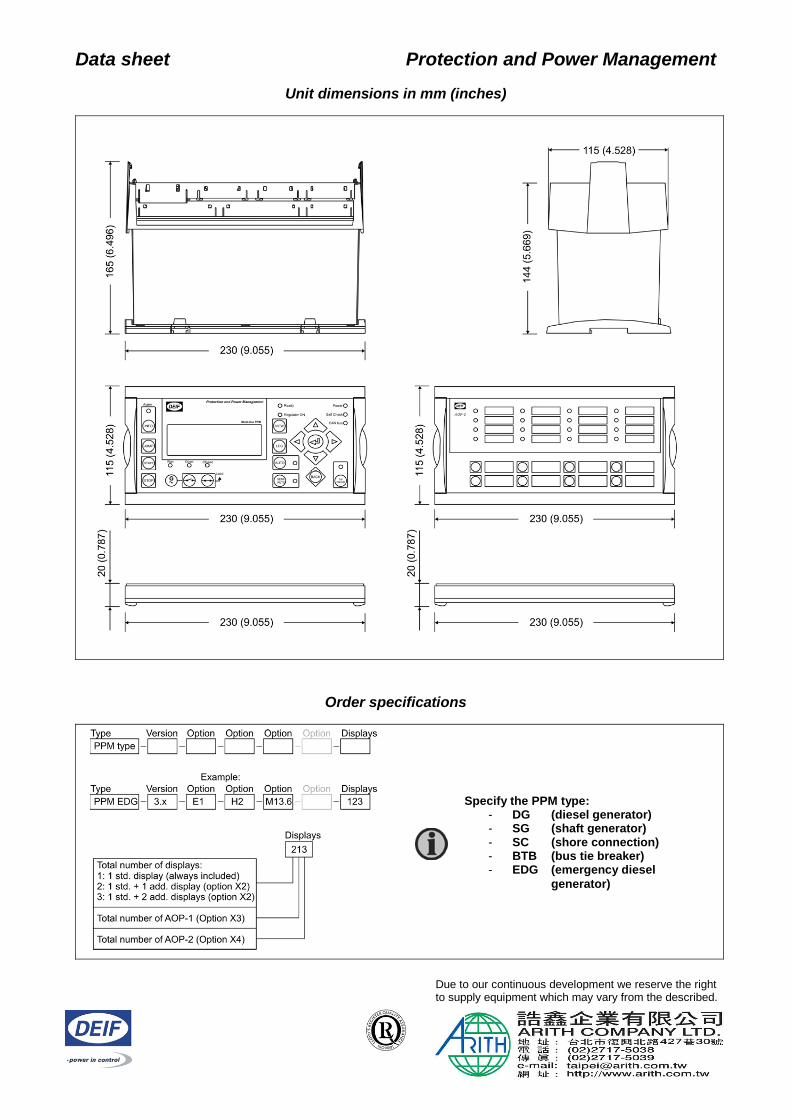
Unit dimensions in mm (inches)
Order specifications
Due to our continuous development we reserve the right to supply equipment which may vary from the described.
Specify the PPM type: - DG (diesel generator) - SG (shaft generator) - SC (shore connection) - BTB (bus tie breaker) - EDG (emergency diesel
generator)