Embed Size (px)
Citation preview
Pump Knowledge Workshop:
Eddy Current Technology
Theory of Operation
Performance Analysis
Application Considerations
Presented by: Gary PattersonPump, Fan & Compressor Technical Sales DirectorDSI/Dynamatic
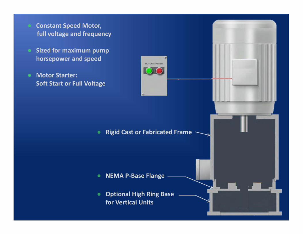
● Constant Speed Motor, full voltage and frequency
● Sized for maximum pump horsepower and speed
● Motor Starter: Soft Start or Full Voltage
● Rigid Cast or Fabricated Frame
● Optional High Ring Base for Vertical Units
● NEMA P‐Base Flange
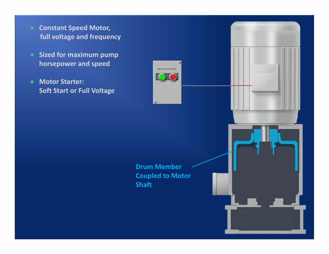
● Constant Speed Motor, full voltage and frequency
● Sized for maximum pump horsepower and speed
● Motor Starter: Soft Start or Full Voltage
Drum Member Coupled to Motor Shaft
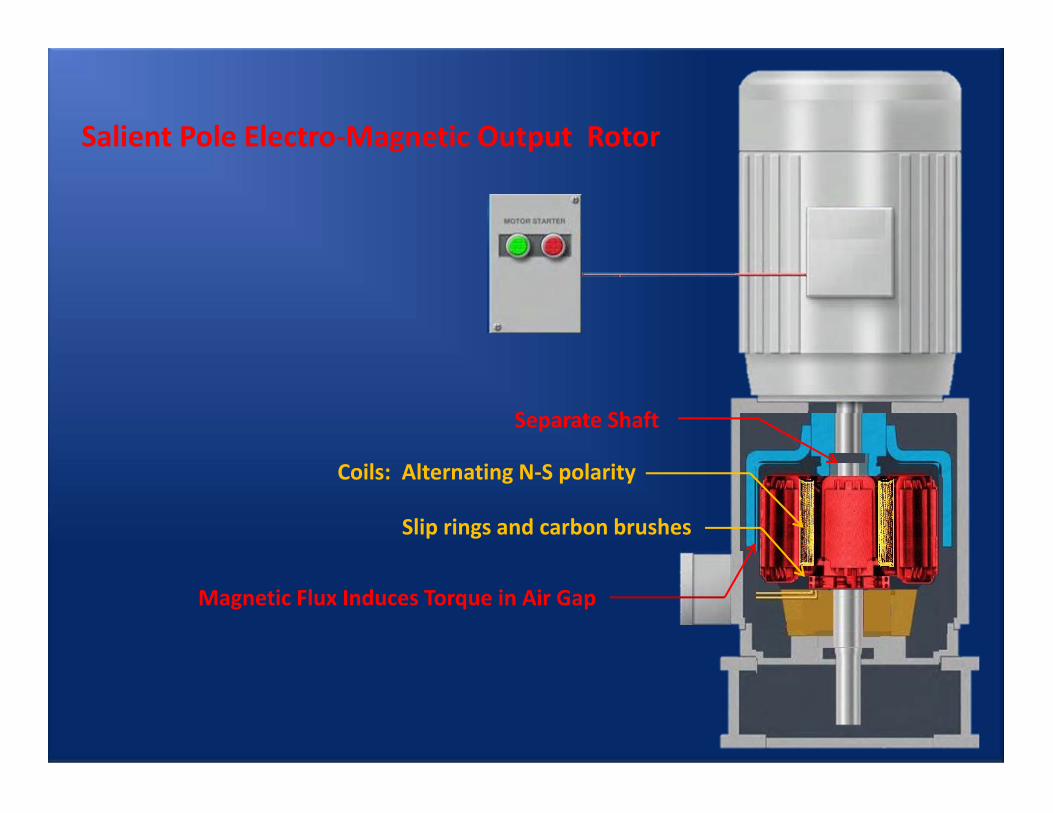
Separate Shaft
Magnetic Flux Induces Torque in Air Gap
Salient Pole Electro‐Magnetic Output Rotor
Coils: Alternating N‐S polarity
Slip rings and carbon brushes
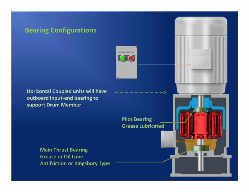
Pilot BearingGrease Lubricated
Main Thrust BearingGrease or Oil LubeAntifriction or Kingsbury Type
Bearing Configurations
Horizontal Coupled units will have outboard input‐end bearing to support Drum Member
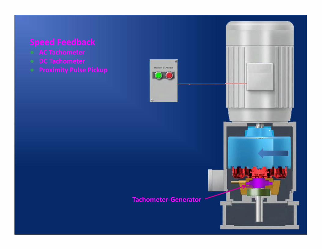
Tachometer‐Generator
Speed Feedback● AC Tachometer● DC Tachometer● Proximity Pulse Pickup
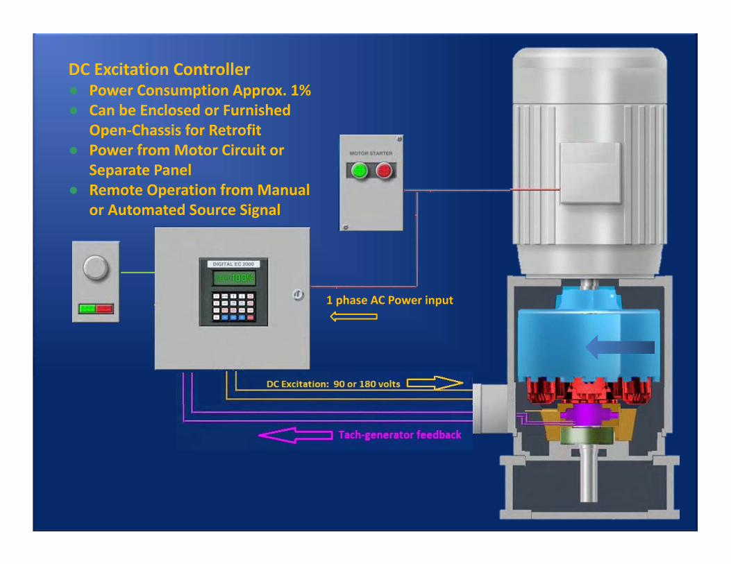
DC Excitation Controller● Power Consumption Approx. 1%● Can be Enclosed or Furnished
Open‐Chassis for Retrofit● Power from Motor Circuit or
Separate Panel● Remote Operation from Manual
or Automated Source Signal
1 phase AC Power input
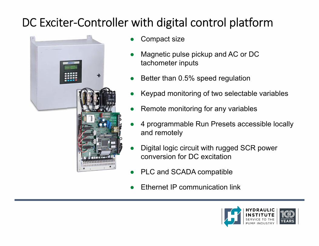
DC Exciter‐Controller with digital control platform● Compact size
● Magnetic pulse pickup and AC or DC tachometer inputs
● Better than 0.5% speed regulation
● Keypad monitoring of two selectable variables
● Remote monitoring for any variables
● 4 programmable Run Presets accessible locally and remotely
● Digital logic circuit with rugged SCR power conversion for DC excitation
● PLC and SCADA compatible
● Ethernet IP communication link
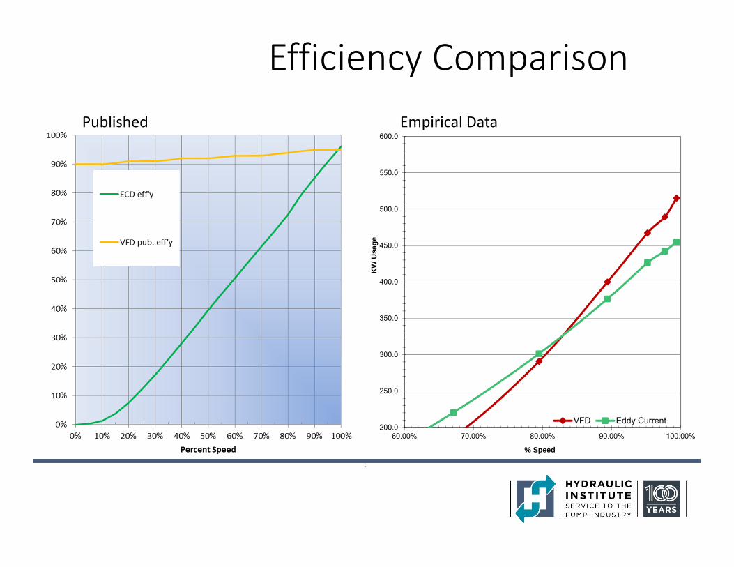
Efficiency ComparisonPublished Empirical Data
.
200.0
250.0
300.0
350.0
400.0
450.0
500.0
550.0
600.0
60.00% 70.00% 80.00% 90.00% 100.00%
KW
Usa
ge
% Speed
VFD Eddy Current
Pump(and fan) Affinity Rule
0%
10%
20%
30%
40%
50%
60%
70%
80%
90%
100%
0% 10% 20% 30% 40% 50% 60% 70% 80% 90% 100%Percent Speed
ECD eff'y
Pump load
Slip loss
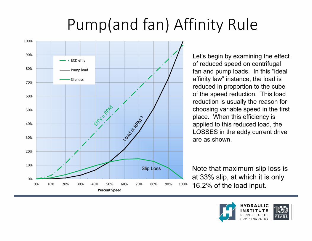
Note that maximum slip loss is at 33% slip, at which it is only 16.2% of the load input.
Let’s begin by examining the effect of reduced speed on centrifugal fan and pump loads. In this “ideal affinity law” instance, the load is reduced in proportion to the cube of the speed reduction. This load reduction is usually the reason for choosing variable speed in the first place. When this efficiency is applied to this reduced load, the LOSSES in the eddy current drive are as shown.
Slip Loss
0%
10%
20%
30%
40%
50%
60%
70%
80%
90%
100%
0% 10% 20% 30% 40% 50% 60% 70% 80% 90% 100%Percent Speed
ECD eff'y
Pump load
ECD loss
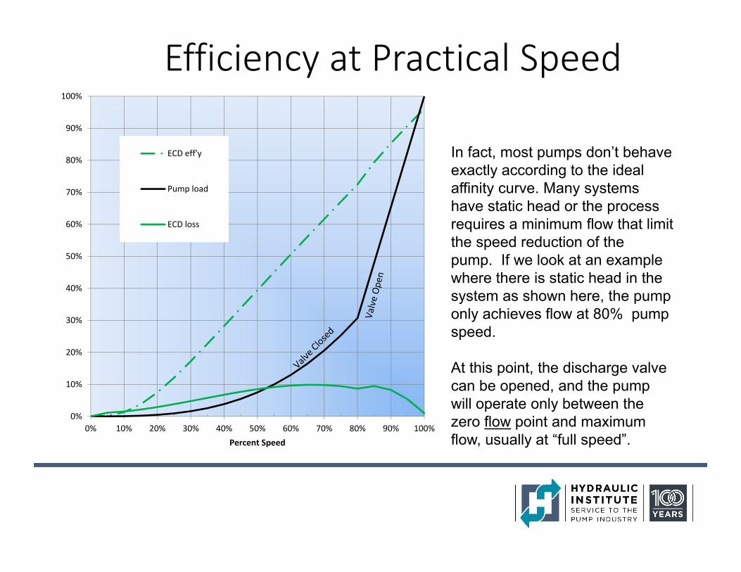
Efficiency at Practical Speed
In fact, most pumps don’t behave exactly according to the ideal affinity curve. Many systems have static head or the process requires a minimum flow that limit the speed reduction of the pump. If we look at an example where there is static head in the system as shown here, the pump only achieves flow at 80% pump speed.
At this point, the discharge valve can be opened, and the pump will operate only between the zero flow point and maximum flow, usually at “full speed”.
0%
10%
20%
30%
40%
50%
60%
70%
80%
90%
100%
0% 10% 20% 30% 40% 50% 60% 70% 80% 90% 100%
ECD eff'y
Pump load
ECD loss
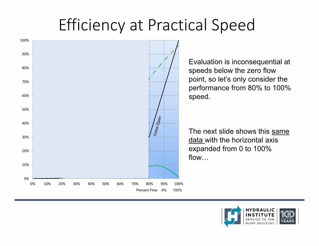
Efficiency at Practical Speed
Evaluation is inconsequential at speeds below the zero flow point, so let’s only consider the performance from 80% to 100% speed.
The next slide shows this same data with the horizontal axis expanded from 0 to 100% flow…
Percent Flow 0% 100%
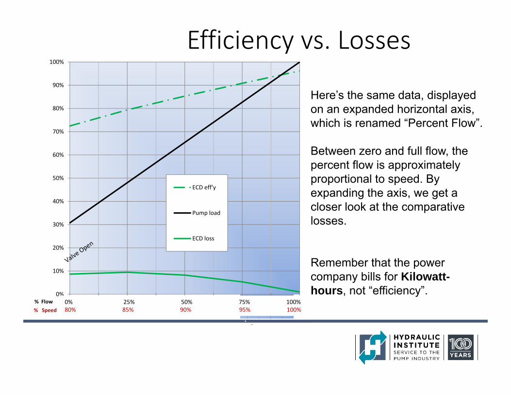
Efficiency vs. Losses
0%
10%
20%
30%
40%
50%
60%
70%
80%
90%
100%
0% 25% 50% 75% 100%
ECD eff'y
Pump load
ECD loss
0% 25% 50% 75% 100%80% 85% 90% 95% 100%% Speed
% Flow
Here’s the same data, displayed on an expanded horizontal axis, which is renamed “Percent Flow”.
Between zero and full flow, the percent flow is approximately proportional to speed. By expanding the axis, we get a closer look at the comparative losses.
Remember that the power company bills for Kilowatt-hours, not “efficiency”.
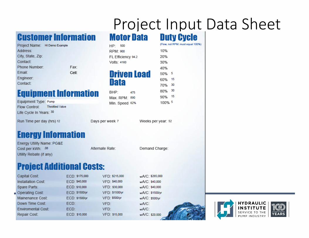
Project Input Data Sheet
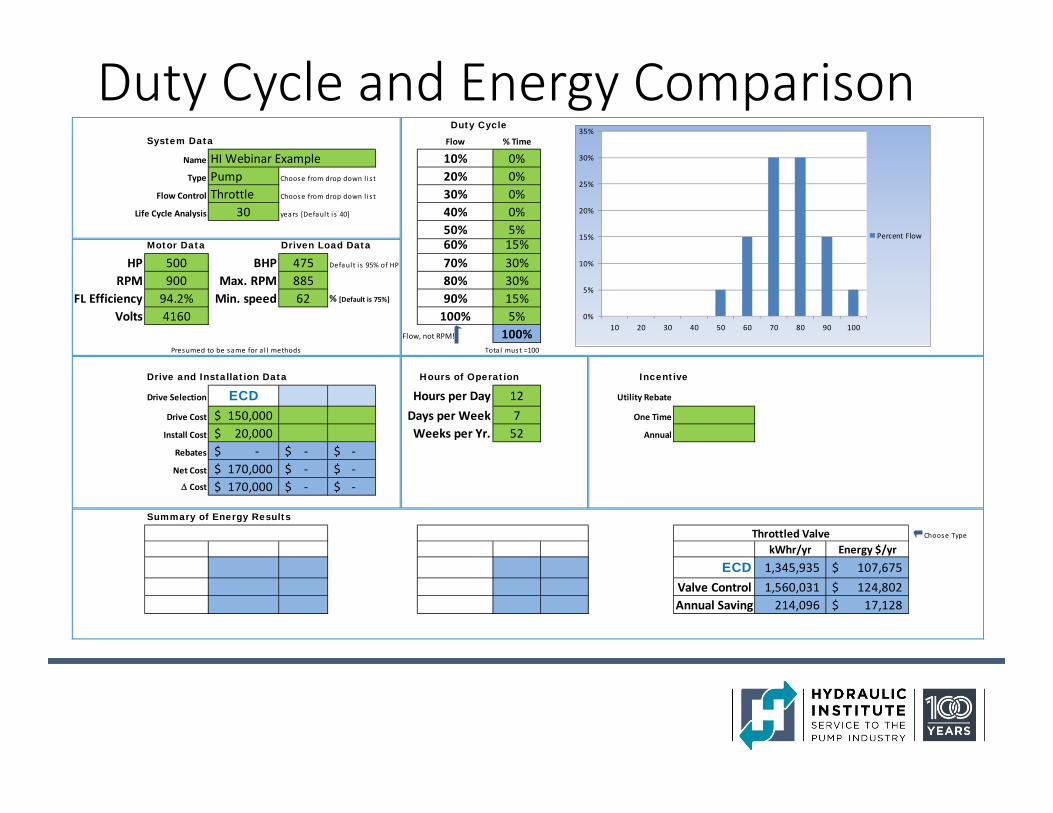
Duty Cycle and Energy ComparisonSystem Data Flow % Time
Name HI Webinar Example 10% 0%Type Pump Choose from drop down l i s t 20% 0%
Flow Control Throttle Choose from drop down l i s t 30% 0%Life Cycle Analysis 30 years [Defaul t i s 40] 40% 0%
50% 5%Motor Data Driven Load Data 60% 15%
HP 500 BHP 475 Defaul t i s 95% of HP 70% 30%RPM 900 Max. RPM 885 80% 30%
FL Efficiency 94.2% Min. speed 62 % [Default is 75%] 90% 15%Volts 4160 100% 5%
Flow, not RPM! 100%Tota l must =100
Hours of Operation Incentive
Drive Selection ECD Hours per Day 12 Utility Rebate
Drive Cost 150,000$ Days per Week 7 One Time
Install Cost 20,000$ Weeks per Yr. 52 Annual
Rebates ‐$ ‐$ ‐$ Net Cost 170,000$ ‐$ ‐$ Cost 170,000$ ‐$ ‐$
Summary of Energy Results
Choose Type
kWhr/yr Energy $/yrECD 1,345,935 107,675$
Valve Control 1,560,031 124,802$ Annual Saving 214,096 17,128$
Throttled Valve
Duty Cycle
Drive and Installation Data
Presumed to be same for al l methods
0%
5%
10%
15%
20%
25%
30%
35%
10 20 30 40 50 60 70 80 90 100
Percent Flow
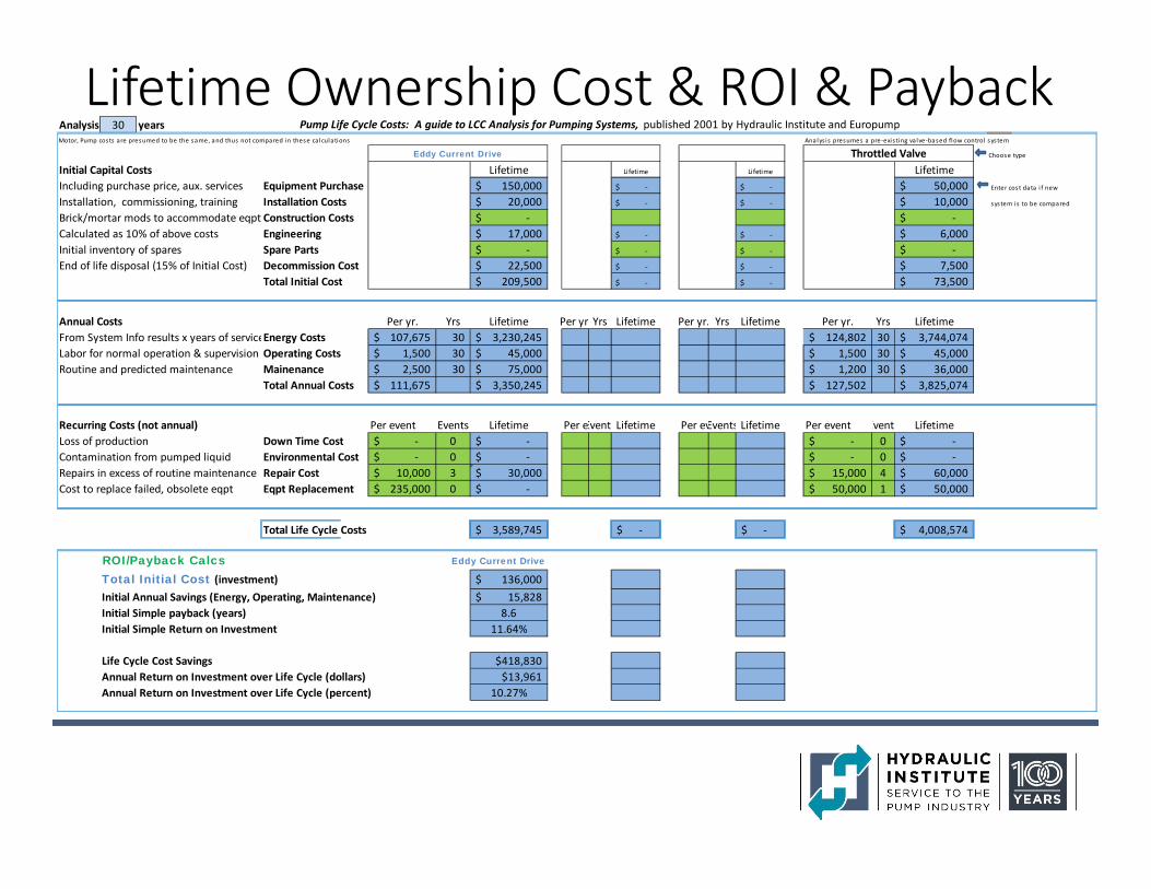
Lifetime Ownership Cost & ROI & PaybackAnalysis 30 years Pump Life Cycle Costs: A guide to LCC Analysis for Pumping Systems, published 2001 by Hydraulic Institute and EuropumpMotor, Pump costs are presumed to be the same, and thus not compared in these cal culations Analys is presumes a pre‐exis ting valve‐based flow control system
Initial Capital Costs Lifetime Lifetime Lifetime LifetimeIncluding purchase price, aux. services Equipment Purchase 150,000$ ‐$ ‐$ 50,000$ Enter cost data i f new
Installation, commissioning, training Installation Costs 20,000$ ‐$ ‐$ 10,000$ system i s to be compared
Brick/mortar mods to accommodate eqpt Construction Costs ‐$ ‐$ Calculated as 10% of above costs Engineering 17,000$ ‐$ ‐$ 6,000$ Initial inventory of spares Spare Parts ‐$ ‐$ ‐$ ‐$ End of life disposal (15% of Initial Cost) Decommission Cost 22,500$ ‐$ ‐$ 7,500$
Total Initial Cost 209,500$ ‐$ ‐$ 73,500$
Annual Costs Per yr. Yrs Lifetime Per yr Yrs Lifetime Per yr. Yrs Lifetime Per yr. Yrs LifetimeFrom System Info results x years of serviceEnergy Costs 107,675$ 30 3,230,245$ 124,802$ 30 3,744,074$ Labor for normal operation & supervision Operating Costs 1,500$ 30 45,000$ 1,500$ 30 45,000$ Routine and predicted maintenance Mainenance 2,500$ 30 75,000$ 1,200$ 30 36,000$
Total Annual Costs 111,675$ 3,350,245$ 127,502$ 3,825,074$
Recurring Costs (not annual) Per event Events Lifetime Per eEvent Lifetime Per evEvents Lifetime Per event Event LifetimeLoss of production Down Time Cost ‐$ 0 ‐$ ‐$ 0 ‐$ Contamination from pumped liquid Environmental Cost ‐$ 0 ‐$ ‐$ 0 ‐$ Repairs in excess of routine maintenance Repair Cost 10,000$ 3 30,000$ 15,000$ 4 60,000$ Cost to replace failed, obsolete eqpt Eqpt Replacement 235,000$ 0 ‐$ 50,000$ 1 50,000$
Total Life Cycle Costs 3,589,745$ ‐$ ‐$ 4,008,574$
ROI/Payback Calcs Eddy Current Drive
Total Initial Cost (investment) 136,000$ Initial Annual Savings (Energy, Operating, Maintenance) 15,828$ Initial Simple payback (years) 8.6Initial Simple Return on Investment 11.64%
Life Cycle Cost Savings $418,830Annual Return on Investment over Life Cycle (dollars) $13,961Annual Return on Investment over Life Cycle (percent) 10.27%
Eddy Current Drive Choose typeThrottled Valve
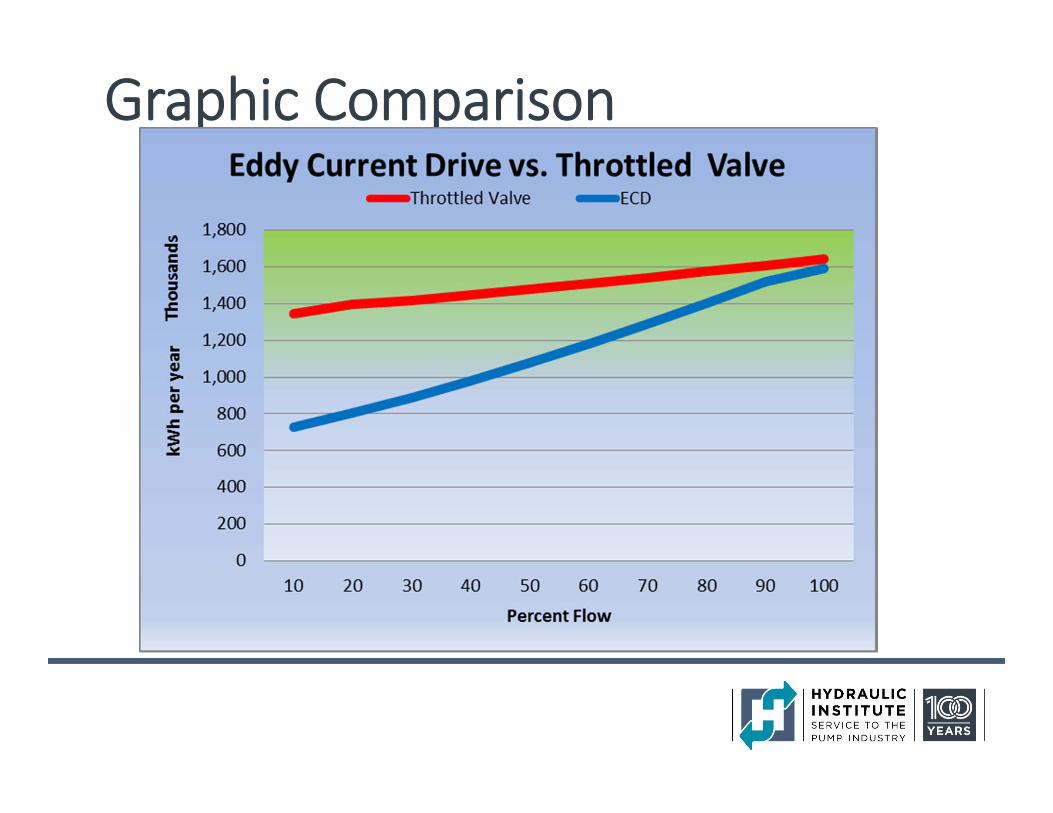
Graphic Comparison
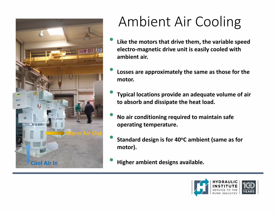
Ambient Air Cooling• Like the motors that drive them, the variable speed
electro‐magnetic drive unit is easily cooled with ambient air.
• Losses are approximately the same as those for the motor.
• Typical locations provide an adequate volume of air to absorb and dissipate the heat load.
• No air conditioning required to maintain safe operating temperature.
• Standard design is for 40oC ambient (same as for motor).
• Higher ambient designs available.Cool Air In
Warm Air Out
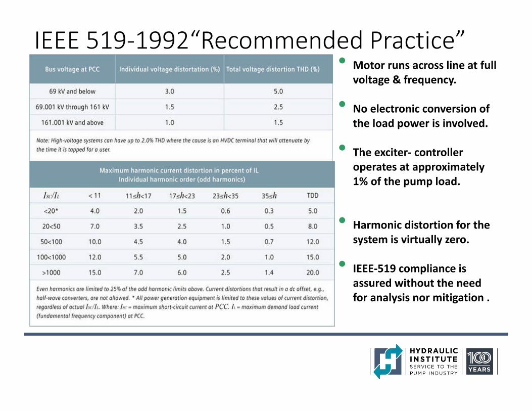
IEEE 519‐1992“Recommended Practice”• Motor runs across line at full
voltage & frequency.
• No electronic conversion of the load power is involved.
• The exciter‐ controller operates at approximately 1% of the pump load.
• Harmonic distortion for the system is virtually zero.
• IEEE‐519 compliance is assured without the need for analysis nor mitigation .
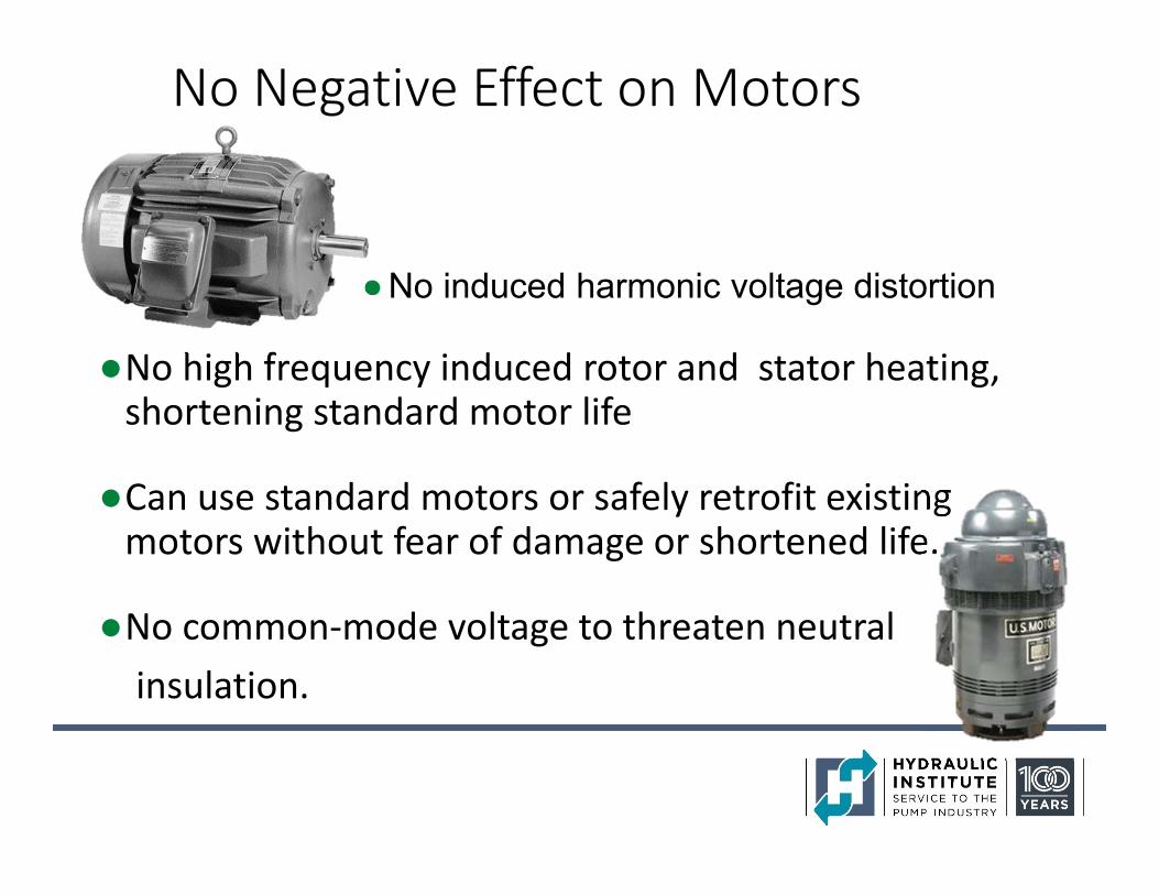
No Negative Effect on Motors
●No induced harmonic voltage distortion
●No high frequency induced rotor and stator heating, shortening standard motor life
●Can use standard motors or safely retrofit existing motors without fear of damage or shortened life.
●No common‐mode voltage to threaten neutral insulation.
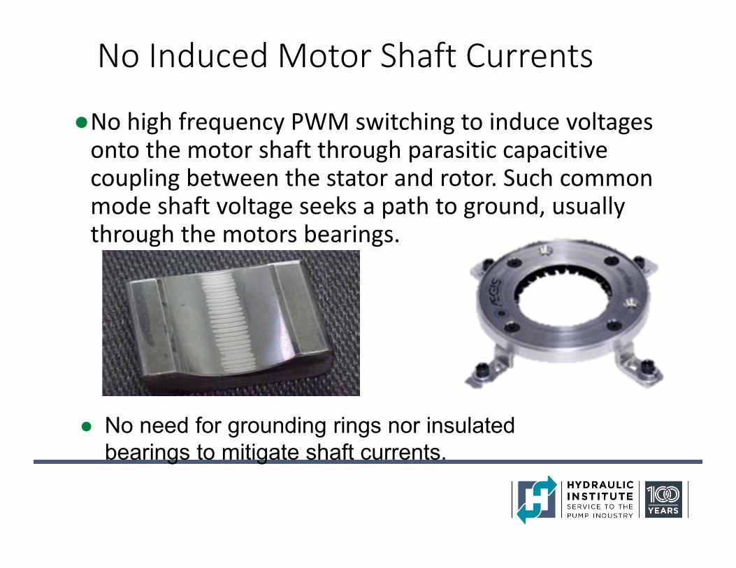
No Induced Motor Shaft Currents
●No high frequency PWM switching to induce voltages onto the motor shaft through parasitic capacitive coupling between the stator and rotor. Such common mode shaft voltage seeks a path to ground, usually through the motors bearings.
● No need for grounding rings nor insulated bearings to mitigate shaft currents.
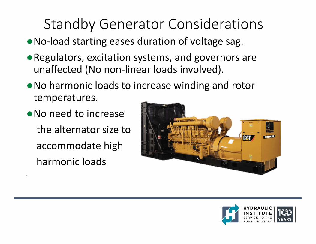
Standby Generator Considerations●No‐load starting eases duration of voltage sag.●Regulators, excitation systems, and governors are unaffected (No non‐linear loads involved).
●No harmonic loads to increase winding and rotor temperatures.
●No need to increasethe alternator size to accommodate high harmonic loads
.
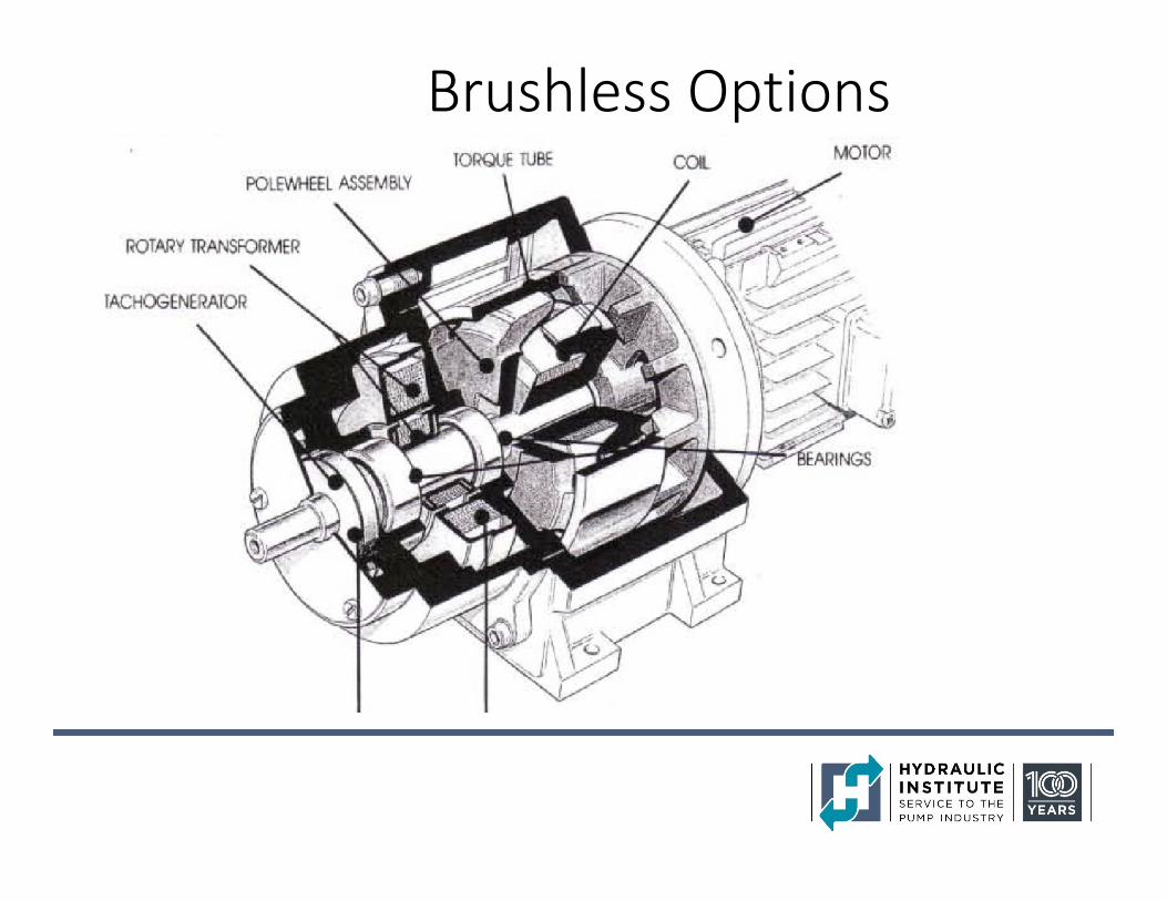
Brushless Options
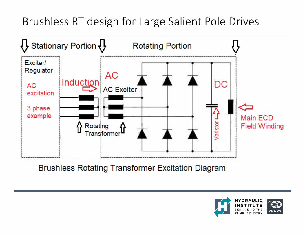
Brushless RT design for Large Salient Pole Drives
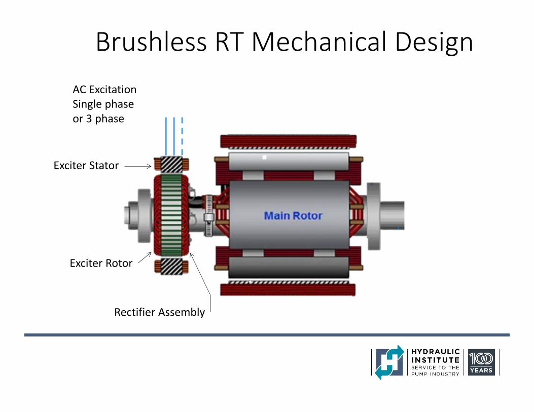
Brushless RT Mechanical Design
Exciter Stator
Exciter Rotor
Rectifier Assembly
AC ExcitationSingle phaseor 3 phase
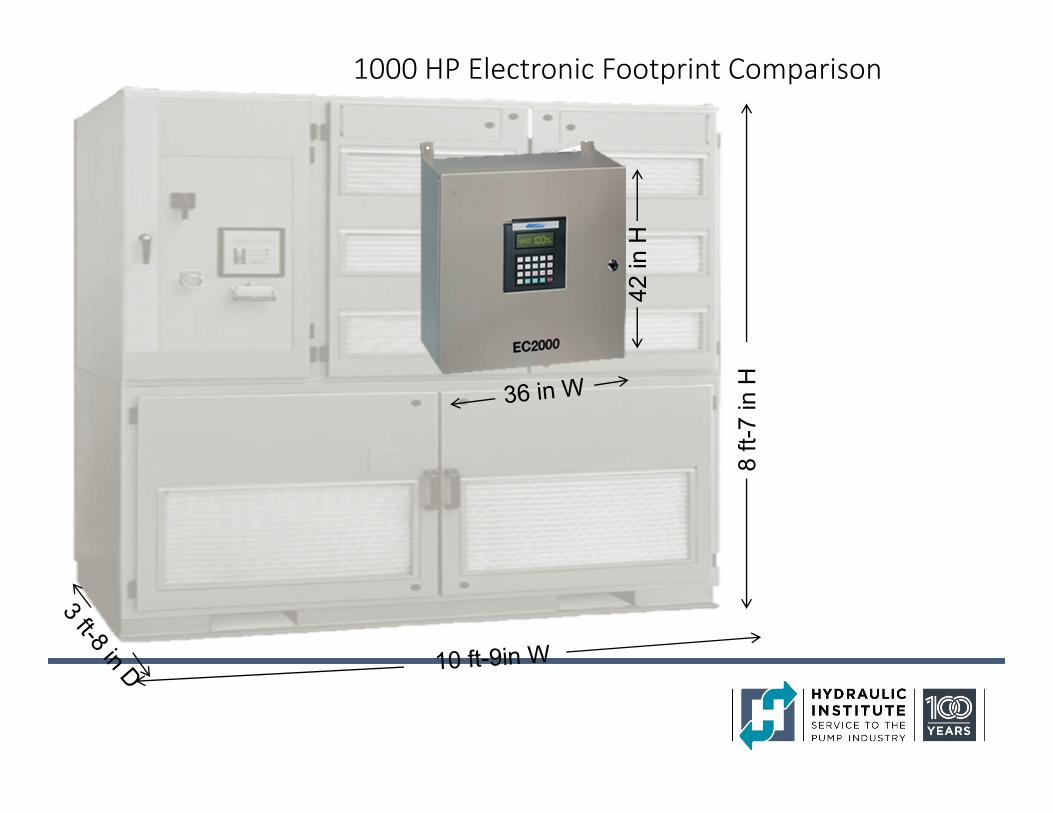
1000 HP Electronic Footprint Comparison
8 ft-
7 in
H
42 in
H
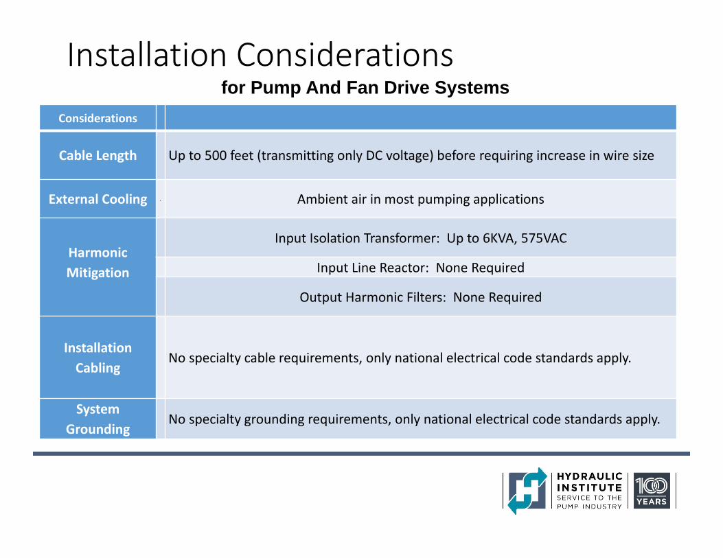
Installation Considerations
Considerations
Cable Length Up to 500 feet (transmitting only DC voltage) before requiring increase in wire size
External Cooling . Ambient air in most pumping applications
Harmonic Mitigation
Input Isolation Transformer: Up to 6KVA, 575VAC
Input Line Reactor: None Required
Output Harmonic Filters: None Required
Installation Cabling
No specialty cable requirements, only national electrical code standards apply.
System Grounding
No specialty grounding requirements, only national electrical code standards apply.
for Pump And Fan Drive Systems
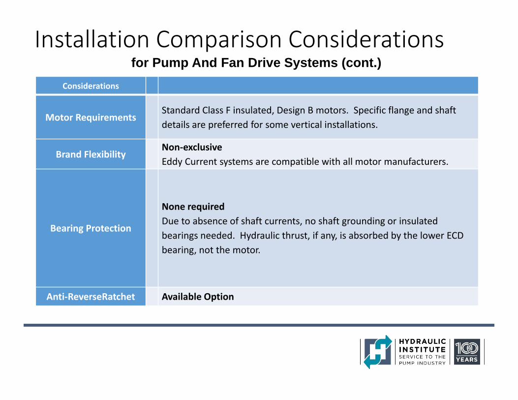
Installation Comparison Considerations
Considerations
Motor RequirementsStandard Class F insulated, Design B motors. Specific flange and shaftdetails are preferred for some vertical installations.
Brand FlexibilityNon‐exclusiveEddy Current systems are compatible with all motor manufacturers.
Bearing Protection
None requiredDue to absence of shaft currents, no shaft grounding or insulated bearings needed. Hydraulic thrust, if any, is absorbed by the lower ECD bearing, not the motor.
Anti‐ReverseRatchet Available Option
for Pump And Fan Drive Systems (cont.)
Additional application considerations
• The additional length of the electromagnetic coupling in horizontal applications
• The additional height of the electromagnetic coupling in vertical applications
• Additional height and weight can reduce natural reed frequencies
• Vertical hollow shaft motors cannot be employed. (any external pump thrust is carried by an optional thrust bearing in the lower end of the electromagnetic drive.)
• Drive units have not been adapted for submersible pumps
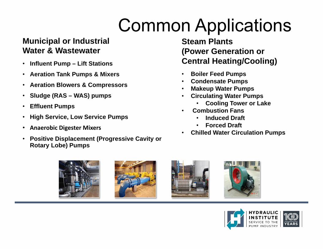
Common Applications
• Influent Pump – Lift Stations
• Aeration Tank Pumps & Mixers
• Aeration Blowers & Compressors
• Sludge (RAS – WAS) pumps
• Effluent Pumps
• High Service, Low Service Pumps
• Anaerobic Digester Mixers
• Positive Displacement (Progressive Cavity or Rotary Lobe) Pumps
Municipal or Industrial Water & Wastewater
• Boiler Feed Pumps• Condensate Pumps• Makeup Water Pumps• Circulating Water Pumps
• Cooling Tower or Lake• Combustion Fans
• Induced Draft• Forced Draft
• Chilled Water Circulation Pumps
Steam Plants (Power Generation or Central Heating/Cooling)
Thanks for Your Attention