Embed Size (px)
Citation preview
PVI‐GSM_GPRS ‐ Quick Installation Guide_EN_rev.1.3_2011‐08‐04
AURORA® PVI-GSM/GPRS MODULE
QUICK INSTALLATION GUIDE
NOTE: THIS DOCUMENT CONTAINS PROPRIETARY INFORMATION OF POWER‐ONE, INC. THE CONTENTS OF THIS DOCUMENT OR ANY PART THEREOF SHOULD NOT BE
REPRODUCED OR DISCLOSED TO ANY THIRD PARTY WITHOUT POWER‐ONE’S EXPRESS WRITTEN CONSENT.
PVI‐GSM_GPRS ‐ Quick Installation Guide_EN_rev.1.3_2011‐08‐04
CONTENTS 1. GENERAL PRODUCT DESCRIPTION
1.1. DESCRIPTION OF EXPANSION MODULE 1.2. PACKAGE CONTENTS
2. INSTALLATION
2.1. SIM CARD: FEATURES AND INSTALLATION 2.2. CONNECTING TO THE PVI‐AEC‐EVO 2.3. CONNECTING THE ANTENNA 2.4. MOUNTING ON DIN RAIL
3. COMMISSIONING 3.1. CHECKS PRIOR TO COMMISSIONING 3.2. COMMISSIONING PROCEDURE 3.3. CONFIGURATION OF DATA TRANSMISSION 3.4. CHECKING MODEM STATUS AND ACTIVITY
3.4.1. MODEM STATUS 3.4.2. MODEM SIGNAL 3.4.3. MODEM ACTIVITY
3.5. CHECKING GSM/GPRS MODEM OPERATION 3.5.1. SENDING SMS 3.5.2. SENDING DATA TO THE PORTAL
4. LIST OF AVAILABLE SMS/TEXT MESSAGES
5. CERTIFICATE OF COMPLIANCE
PVI‐GSM_GPRS ‐ Quick Installation Guide_EN_rev.1.3_2011‐08‐04
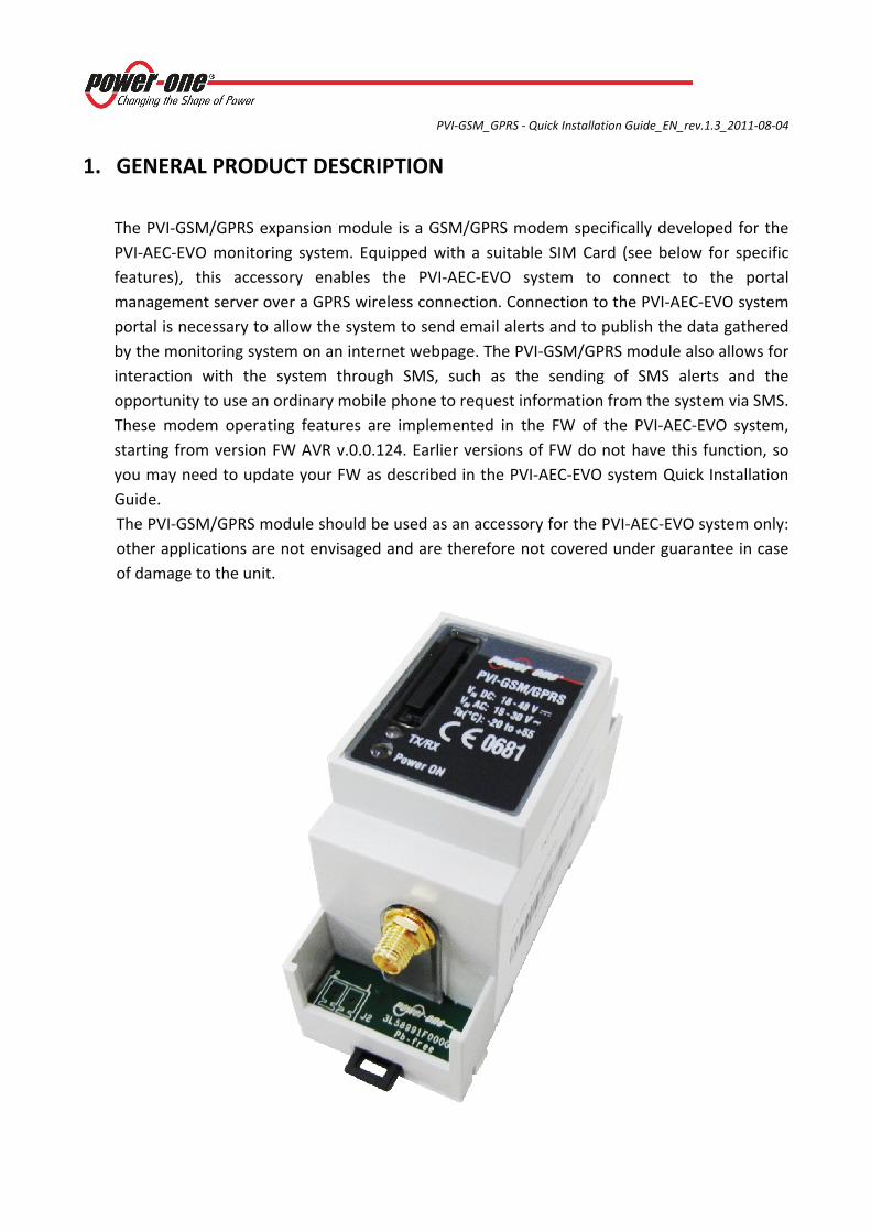
1. GENERAL PRODUCT DESCRIPTION The PVI‐GSM/GPRS expansion module is a GSM/GPRS modem specifically developed for the PVI‐AEC‐EVO monitoring system. Equipped with a suitable SIM Card (see below for specific features), this accessory enables the PVI‐AEC‐EVO system to connect to the portal management server over a GPRS wireless connection. Connection to the PVI‐AEC‐EVO system portal is necessary to allow the system to send email alerts and to publish the data gathered by the monitoring system on an internet webpage. The PVI‐GSM/GPRS module also allows for interaction with the system through SMS, such as the sending of SMS alerts and the opportunity to use an ordinary mobile phone to request information from the system via SMS. These modem operating features are implemented in the FW of the PVI‐AEC‐EVO system, starting from version FW AVR v.0.0.124. Earlier versions of FW do not have this function, so you may need to update your FW as described in the PVI‐AEC‐EVO system Quick Installation Guide. The PVI‐GSM/GPRS module should be used as an accessory for the PVI‐AEC‐EVO system only: other applications are not envisaged and are therefore not covered under guarantee in case of damage to the unit.
PVI‐GSM_GPRS ‐ Quick Installation Guide_EN_rev.1.3_2011‐08‐04
1.1. DESCRIPTION OF EXPANSION MODULE
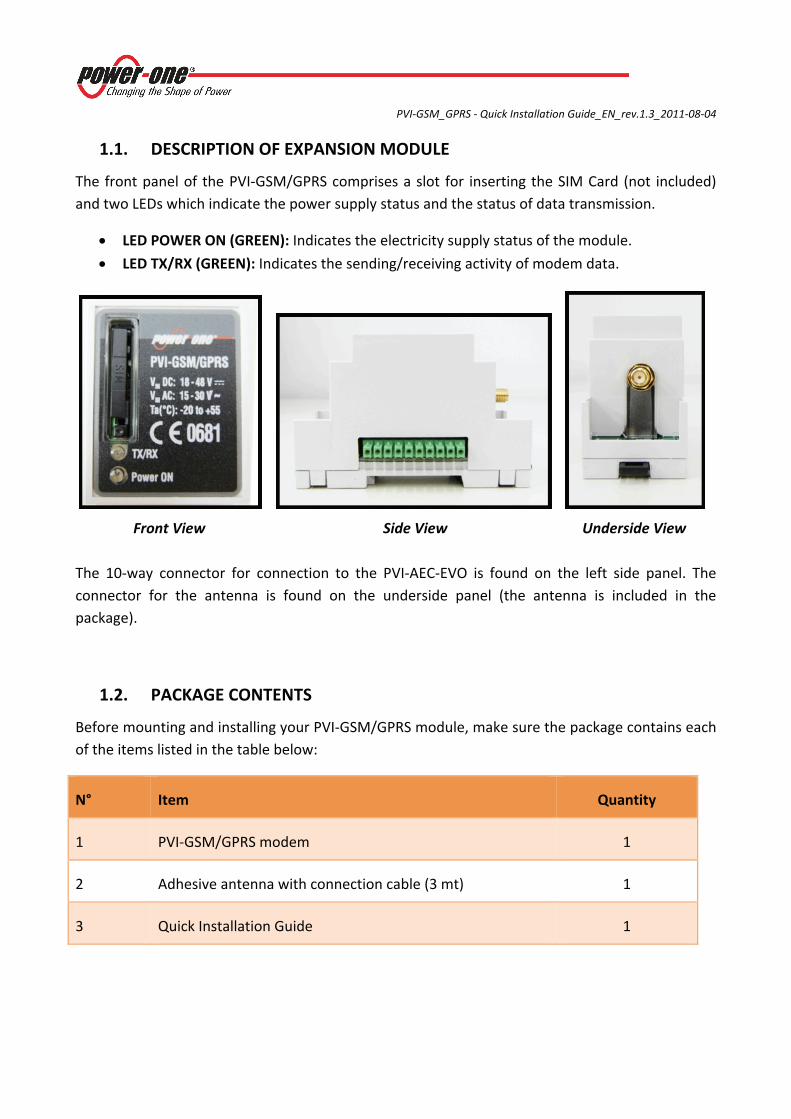
The front panel of the PVI‐GSM/GPRS comprises a slot for inserting the SIM Card (not included) and two LEDs which indicate the power supply status and the status of data transmission.
• LED POWER ON (GREEN): Indicates the electricity supply status of the module.
• LED TX/RX (GREEN): Indicates the sending/receiving activity of modem data.
Front View Side View Underside View
The 10‐way connector for connection to the PVI‐AEC‐EVO is found on the left side panel. The connector for the antenna is found on the underside panel (the antenna is included in the package).
1.2. PACKAGE CONTENTS
Before mounting and installing your PVI‐GSM/GPRS module, make sure the package contains each of the items listed in the table below:
N° Item Quantity
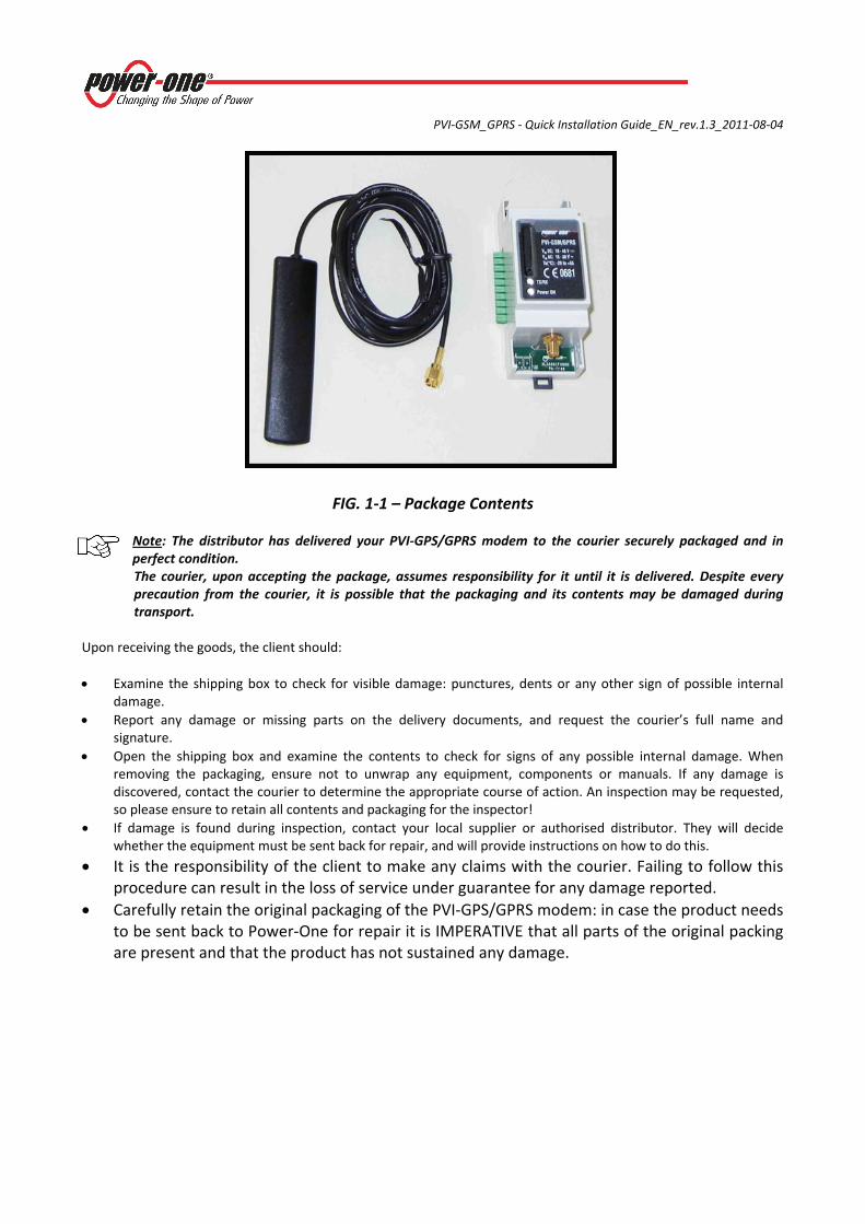
1 PVI‐GSM/GPRS modem 1
2 Adhesive antenna with connection cable (3 mt) 1
3 Quick Installation Guide 1
PVI‐GSM_GPRS ‐ Quick Installation Guide_EN_rev.1.3_2011‐08‐04
FIG. 1‐1 – Package Contents
Note: The distributor has delivered your PVI‐GPS/GPRS modem to the courier securely packaged and in perfect condition. The courier, upon accepting the package, assumes responsibility for it until it is delivered. Despite every precaution from the courier, it is possible that the packaging and its contents may be damaged during transport.
Upon receiving the goods, the client should: • Examine the shipping box to check for visible damage: punctures, dents or any other sign of possible internal
damage. • Report any damage or missing parts on the delivery documents, and request the courier’s full name and
signature. • Open the shipping box and examine the contents to check for signs of any possible internal damage. When
removing the packaging, ensure not to unwrap any equipment, components or manuals. If any damage is discovered, contact the courier to determine the appropriate course of action. An inspection may be requested, so please ensure to retain all contents and packaging for the inspector!
• If damage is found during inspection, contact your local supplier or authorised distributor. They will decide whether the equipment must be sent back for repair, and will provide instructions on how to do this.
• It is the responsibility of the client to make any claims with the courier. Failing to follow this procedure can result in the loss of service under guarantee for any damage reported.
• Carefully retain the original packaging of the PVI‐GPS/GPRS modem: in case the product needs to be sent back to Power‐One for repair it is IMPERATIVE that all parts of the original packing are present and that the product has not sustained any damage.
PVI‐GSM_GPRS ‐ Quick Installation Guide_EN_rev.1.3_2011‐08‐04
2. INSTALLATION 2.1. SIM CARD: FEATURES AND INSTALLATIONS
In order to enable the PVI‐GSM/GPRS modem to send data collected by the PVI‐AEC‐EVO, it is necessary to insert into the specific slot a SIM Card with the following features:
• a contract deal SIM Card (*)
• SIM Card enabled for GPRS service
• Machine‐to‐Machine SIM Card (M2M)
• Enabled for fax/data traffic and SMS, both incoming and outgoing.
(*) The use of a Pay As You Go SIM Card is strongly discouraged as it may not allow the required services to function with the system. Power‐One declines all responsibility in the event of operational problems resulting from the use of SIM Cards failing to meet the criteria listed above and/or relating to inefficiency of the mobile phone service provider.
Note The PIN Code must be disabled before inserting the SIM Card into the system: this can be done by inserting the SIM Card into any ordinary mobile telephone.
To insert the SIM Card:
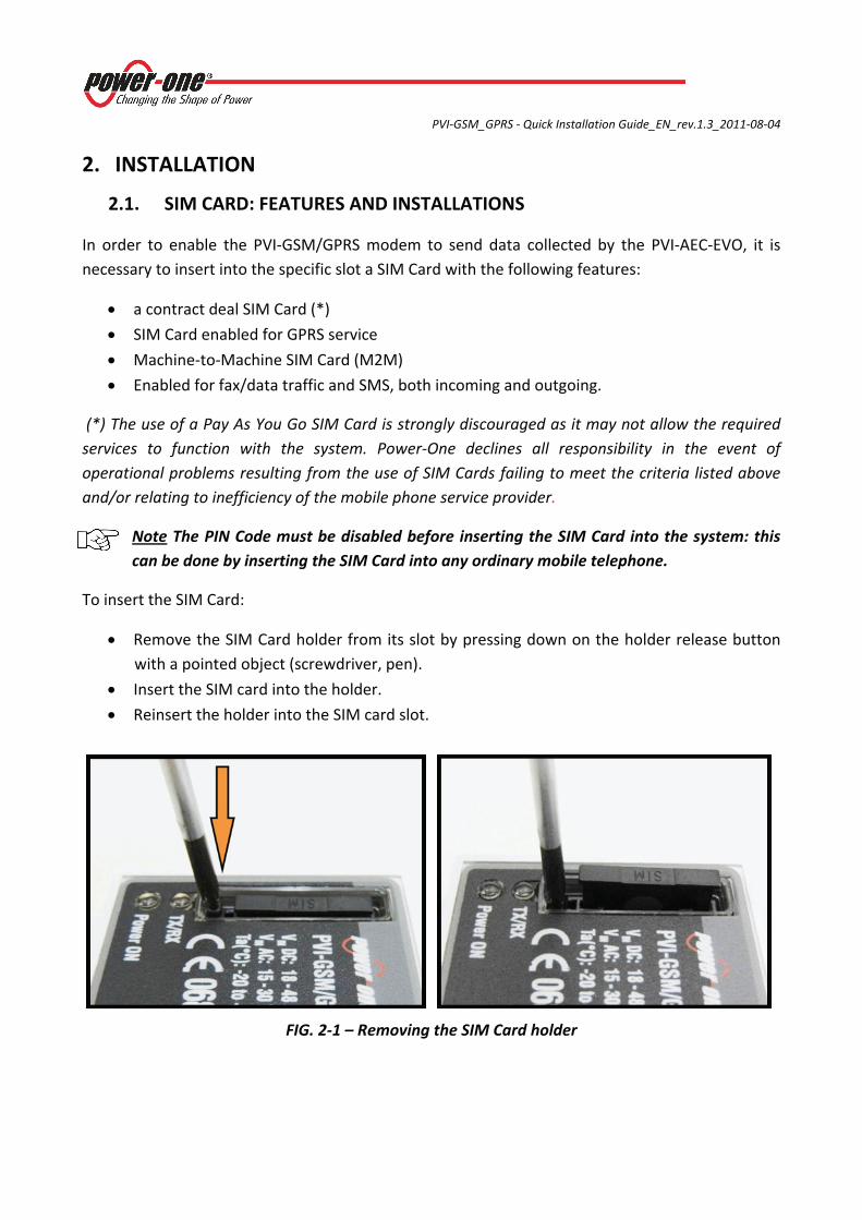
• Remove the SIM Card holder from its slot by pressing down on the holder release button with a pointed object (screwdriver, pen).
• Insert the SIM card into the holder.
• Reinsert the holder into the SIM card slot.
FIG. 2‐1 – Removing the SIM Card holder
PVI‐GSM_GPRS ‐ Quick Installation Guide_EN_rev.1.3_2011‐08‐04
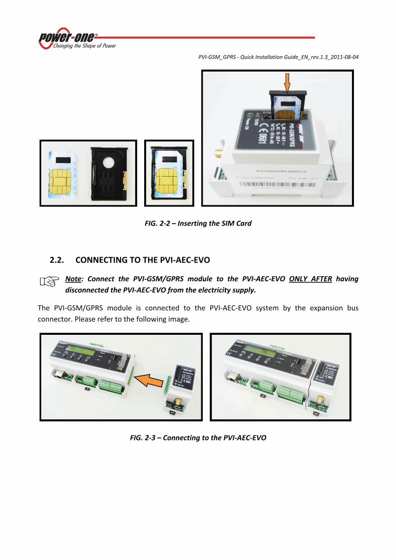
FIG. 2‐2 – Inserting the SIM Card
2.2. CONNECTING TO THE PVI‐AEC‐EVO
Note: Connect the PVI‐GSM/GPRS module to the PVI‐AEC‐EVO ONLY AFTER having disconnected the PVI‐AEC‐EVO from the electricity supply.
The PVI‐GSM/GPRS module is connected to the PVI‐AEC‐EVO system by the expansion bus connector. Please refer to the following image.
FIG. 2‐3 – Connecting to the PVI‐AEC‐EVO
PVI‐GSM_GPRS ‐ Quick Installation Guide_EN_rev.1.3_2011‐08‐04
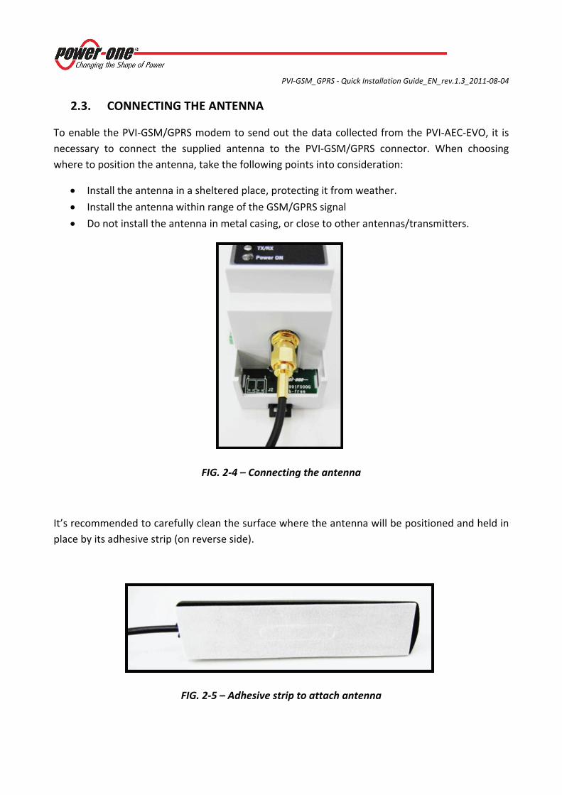
2.3. CONNECTING THE ANTENNA
To enable the PVI‐GSM/GPRS modem to send out the data collected from the PVI‐AEC‐EVO, it is necessary to connect the supplied antenna to the PVI‐GSM/GPRS connector. When choosing where to position the antenna, take the following points into consideration:
• Install the antenna in a sheltered place, protecting it from weather.
• Install the antenna within range of the GSM/GPRS signal
• Do not install the antenna in metal casing, or close to other antennas/transmitters.
FIG. 2‐4 – Connecting the antenna
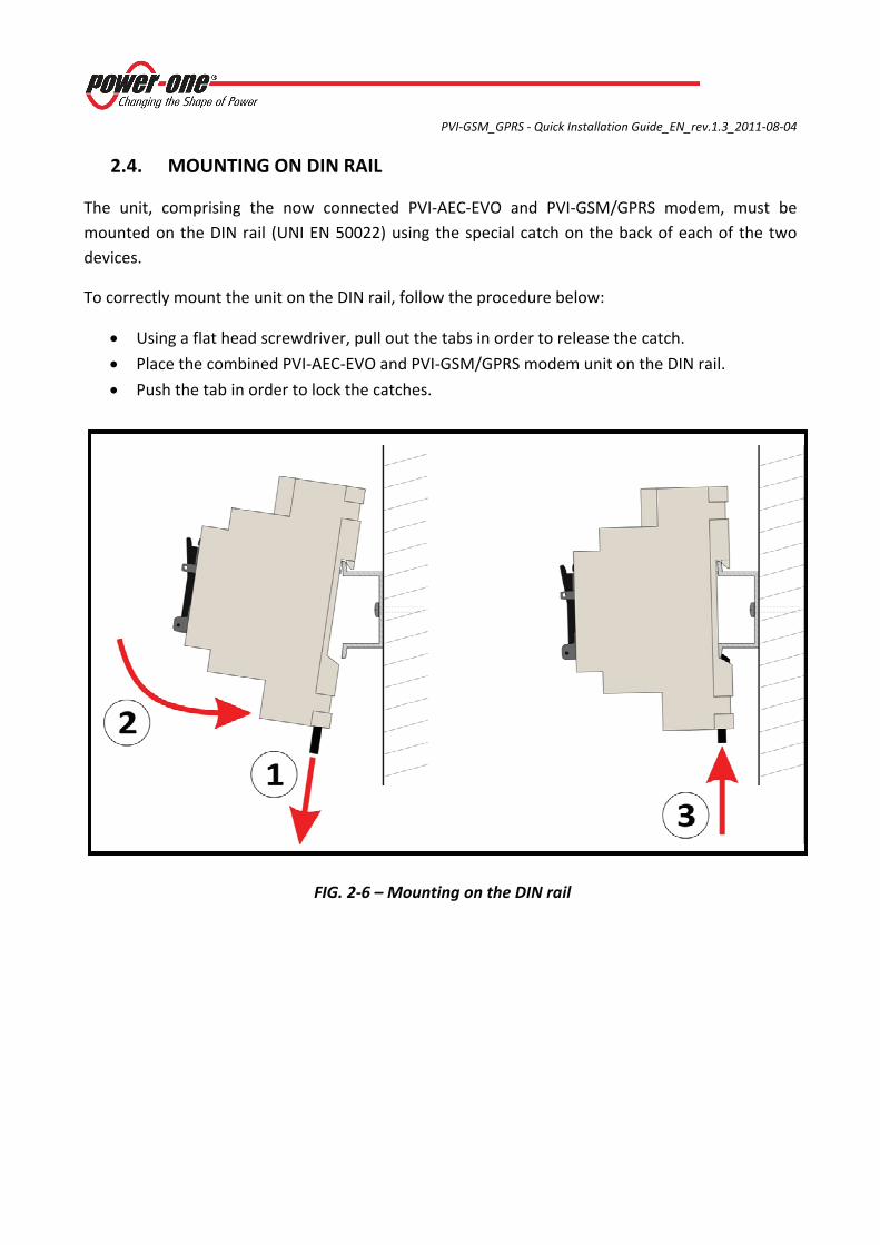
It’s recommended to carefully clean the surface where the antenna will be positioned and held in place by its adhesive strip (on reverse side).
FIG. 2‐5 – Adhesive strip to attach antenna
PVI‐GSM_GPRS ‐ Quick Installation Guide_EN_rev.1.3_2011‐08‐04
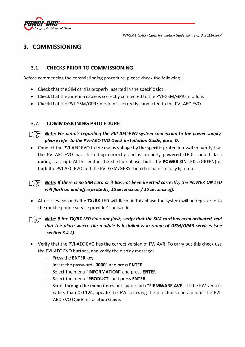
2.4. MOUNTING ON DIN RAIL
The unit, comprising the now connected PVI‐AEC‐EVO and PVI‐GSM/GPRS modem, must be mounted on the DIN rail (UNI EN 50022) using the special catch on the back of each of the two devices.
To correctly mount the unit on the DIN rail, follow the procedure below:
• Using a flat head screwdriver, pull out the tabs in order to release the catch.
• Place the combined PVI‐AEC‐EVO and PVI‐GSM/GPRS modem unit on the DIN rail.
• Push the tab in order to lock the catches.
FIG. 2‐6 – Mounting on the DIN rail
PVI‐GSM_GPRS ‐ Quick Installation Guide_EN_rev.1.3_2011‐08‐04
3. COMMISSIONING
3.1. CHECKS PRIOR TO COMMISSIONING
Before commencing the commissioning procedure, please check the following:
• Check that the SIM card is properly inserted in the specific slot.
• Check that the antenna cable is correctly connected to the PVI‐GSM/GPRS module.
• Check that the PVI‐GSM/GPRS modem is correctly connected to the PVI‐AEC‐EVO.
3.2. COMMISSIONING PROCEDURE
Note: For details regarding the PVI‐AEC‐EVO system connection to the power supply, please refer to the PVI‐AEC‐EVO Quick Installation Guide, para. D.
• Connect the PVI‐AEC‐EVO to the mains voltage by the specific protection switch. Verify that the PVI‐AEC‐EVO has started‐up correctly and is properly powered (LEDs should flash during start‐up). At the end of the start‐up phase, both the POWER ON LEDs (GREEN) of both the PVI‐AEC‐EVO and the PVI‐GSM/GPRS should remain steadily light up.
Note: If there is no SIM card or it has not been inserted correctly, the POWER ON LED will flash on and off repeatedly, 15 seconds on / 15 seconds off.
• After a few seconds the TX/RX LED will flash: in this phase the system will be registered to the mobile phone service provider’s network.
Note: If the TX/RX LED does not flash, verify that the SIM card has been activated, and that the place where the module is installed is in range of GSM/GPRS services (see section 3.4.2).
• Verify that the PVI‐AEC‐EVO has the correct version of FW AVR. To carry out this check use the PVI‐AEC‐EVO buttons, and verify the display messages:
‐ Press the ENTER key ‐ Insert the password “0000” and press ENTER ‐ Select the menu “INFORMATION” and press ENTER ‐ Select the menu “PRODUCT” and press ENTER ‐ Scroll through the menu items until you reach “FIRMWARE AVR”. If the FW version
is less than 0.0.124, update the FW following the directions contained in the PVI‐AEC‐EVO Quick Installation Guide.
PVI‐GSM_GPRS ‐ Quick Installation Guide_EN_rev.1.3_2011‐08‐04
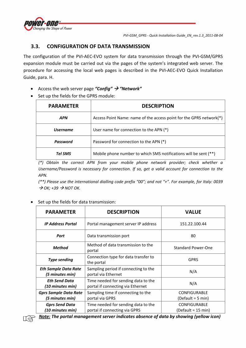
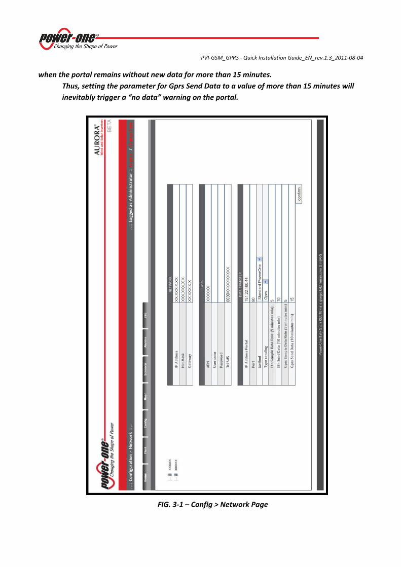
3.3. CONFIGURATION OF DATA TRANSMISSION
The configuration of the PVI‐AEC‐EVO system for data transmission through the PVI‐GSM/GPRS expansion module must be carried out via the pages of the system’s integrated web server. The procedure for accessing the local web pages is described in the PVI‐AEC‐EVO Quick Installation Guide, para. H.
• Access the web server page “Config” “Network”
• Set up the fields for the GPRS module:
PARAMETER DESCRIPTION
APN Access Point Name: name of the access point for the GPRS network(*)
Username User name for connection to the APN (*)
Password Password for connection to the APN (*)
Tel SMS Mobile phone number to which SMS notifications will be sent (**)
(*) Obtain the correct APN from your mobile phone network provider; check whether a Username/Password is necessary for connection. If so, get a valid account for connection to the APN. (**) Please use the international dialling code prefix “00”; and not “+”. For example, for Italy: 0039
OK; +39 NOT OK.
• Set up the fields for data transmission:
PARAMETER DESCRIPTION VALUE
IP Address Portal Portal management server IP address 151.22.100.44
Port Data transmission port 80
Method Method of data transmission to the portal
Standard Power‐One
Type sending Connection type for data transfer to the portal
GPRS
Eth Sample Data Rate (5 minutes min)
Sampling period if connecting to the portal via Ethernet
N/A
Eth Send Data (10 minutes min)
Time needed for sending data to the portal if connecting via Ethernet
N/A
Gprs Sample Data Rate (5 minutes min)
Sampling time if connecting to the portal via GPRS
CONFIGURABLE (Default = 5 min)
Gprs Send Data (10 minutes min)
Time needed for sending data to the portal if connecting via GPRS
CONFIGURABLE (Default = 15 min)
Note: The portal management server indicates absence of data by showing (yellow icon)
PVI‐GSM_GPRS ‐ Quick Installation Guide_EN_rev.1.3_2011‐08‐04
when the portal remains without new data for more than 15 minutes.
Thus, setting the parameter for Gprs Send Data to a value of more than 15 minutes will inevitably trigger a “no data” warning on the portal.
FIG. 3‐1 – Config > Network Page
PVI‐GSM_GPRS ‐ Quick Installation Guide_EN_rev.1.3_2011‐08‐04
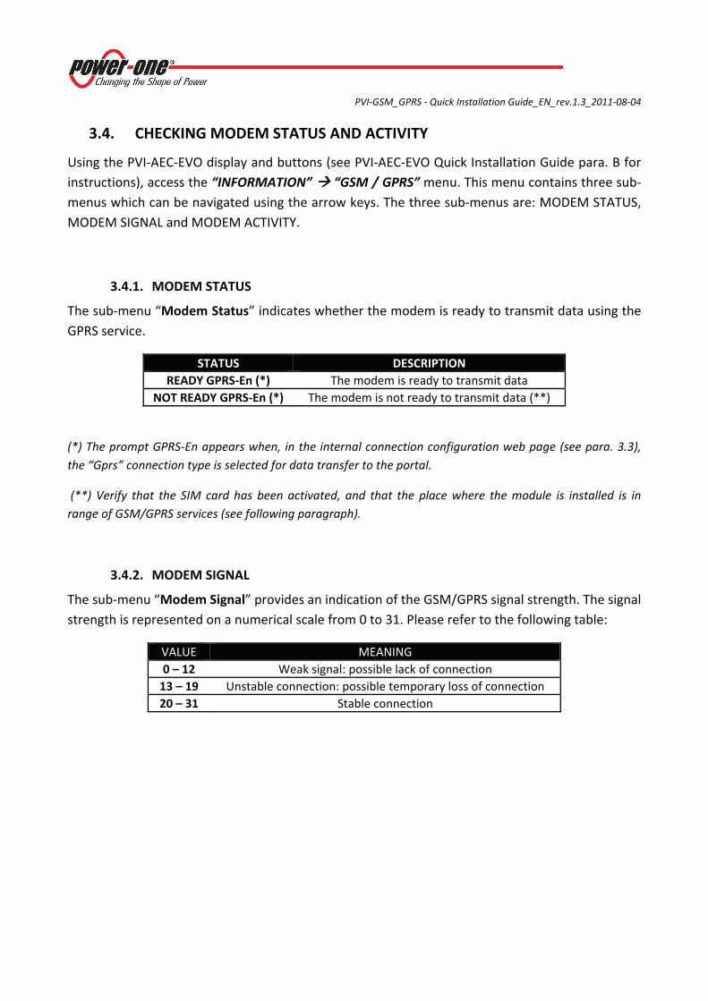
3.4. CHECKING MODEM STATUS AND ACTIVITY
Using the PVI‐AEC‐EVO display and buttons (see PVI‐AEC‐EVO Quick Installation Guide para. B for instructions), access the “INFORMATION” “GSM / GPRS” menu. This menu contains three sub‐menus which can be navigated using the arrow keys. The three sub‐menus are: MODEM STATUS, MODEM SIGNAL and MODEM ACTIVITY.
3.4.1. MODEM STATUS
The sub‐menu “Modem Status” indicates whether the modem is ready to transmit data using the GPRS service.
STATUS DESCRIPTION READY GPRS‐En (*) The modem is ready to transmit data
NOT READY GPRS‐En (*) The modem is not ready to transmit data (**)
(*) The prompt GPRS‐En appears when, in the internal connection configuration web page (see para. 3.3), the “Gprs” connection type is selected for data transfer to the portal.
(**) Verify that the SIM card has been activated, and that the place where the module is installed is in range of GSM/GPRS services (see following paragraph).
3.4.2. MODEM SIGNAL
The sub‐menu “Modem Signal” provides an indication of the GSM/GPRS signal strength. The signal strength is represented on a numerical scale from 0 to 31. Please refer to the following table:
VALUE MEANING 0 – 12 Weak signal: possible lack of connection 13 – 19 Unstable connection: possible temporary loss of connection 20 – 31 Stable connection
PVI‐GSM_GPRS ‐ Quick Installation Guide_EN_rev.1.3_2011‐08‐04
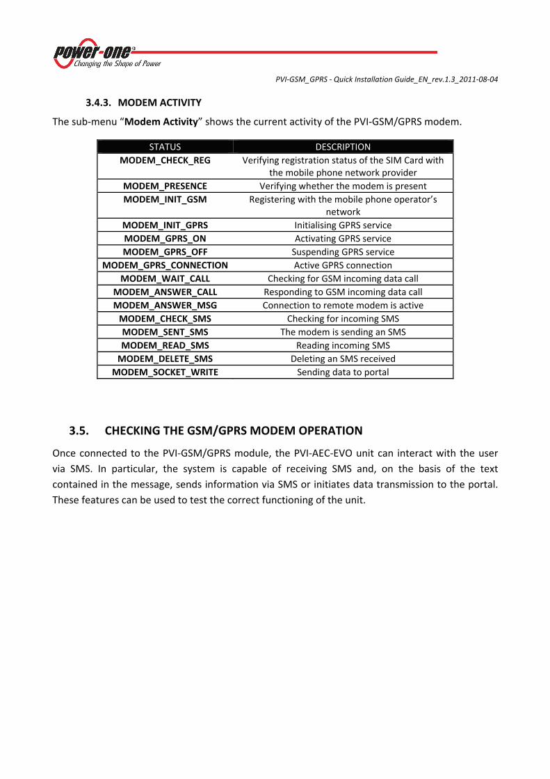
3.4.3. MODEM ACTIVITY
The sub‐menu “Modem Activity” shows the current activity of the PVI‐GSM/GPRS modem.
STATUS DESCRIPTION MODEM_CHECK_REG Verifying registration status of the SIM Card with
the mobile phone network provider MODEM_PRESENCE Verifying whether the modem is present MODEM_INIT_GSM Registering with the mobile phone operator’s
network MODEM_INIT_GPRS Initialising GPRS service MODEM_GPRS_ON Activating GPRS service MODEM_GPRS_OFF Suspending GPRS service
MODEM_GPRS_CONNECTION Active GPRS connection MODEM_WAIT_CALL Checking for GSM incoming data call
MODEM_ANSWER_CALL Responding to GSM incoming data call MODEM_ANSWER_MSG Connection to remote modem is active MODEM_CHECK_SMS Checking for incoming SMS MODEM_SENT_SMS The modem is sending an SMS MODEM_READ_SMS Reading incoming SMS MODEM_DELETE_SMS Deleting an SMS received
MODEM_SOCKET_WRITE Sending data to portal
3.5. CHECKING THE GSM/GPRS MODEM OPERATION
Once connected to the PVI‐GSM/GPRS module, the PVI‐AEC‐EVO unit can interact with the user via SMS. In particular, the system is capable of receiving SMS and, on the basis of the text contained in the message, sends information via SMS or initiates data transmission to the portal. These features can be used to test the correct functioning of the unit.
PVI‐GSM_GPRS ‐ Quick Installation Guide_EN_rev.1.3_2011‐08‐04
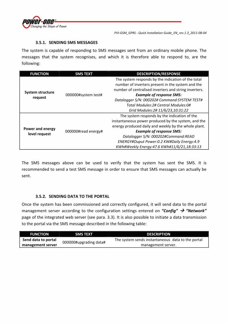
3.5.1. SENDING SMS MESSAGES
The system is capable of responding to SMS messages sent from an ordinary mobile phone. The messages that the system recognises, and which it is therefore able to respond to, are the following:
FUNCTION SMS TEXT DESCRIPTION/RESPONSE
System structure request
000000#system test#
The system responds by the indication of the total number of inverters present in the system and the number of centralised inverters and string inverters.
Example of response SMS: Datalogger S/N: 000202# Command:SYSTEM TEST#
Total Modules:2# Central Modules:0# Grid Modules:2# 11/6/23,10:31:22
Power and energy level request
000000#read energy#
The system responds by the indication of the instantaneous power produced by the system, and the energy produced daily and weekly by the whole plant.
Example of response SMS: Datalogger S/N: 000202#Command:READ
ENERGY#Ouput Power:0.2 KW#Daily Energy:4.9 KWh#Weekly Energy:47.6 KWh#11/6/21,18:33:13
The SMS messages above can be used to verify that the system has sent the SMS. It is recommended to send a test SMS message in order to ensure that SMS messages can actually be sent.
3.5.2. SENDING DATA TO THE PORTAL Once the system has been commissioned and correctly configured, it will send data to the portal management server according to the configuration settings entered on “Config” “Network” page of the integrated web server (see para. 3.3). It is also possible to initiate a data transmission to the portal via the SMS message described in the following table:
FUNCTION SMS TEXT DESCRIPTION Send data to portal management server
000000#upgrading data# The system sends instantaneous data to the portal
management server.
PVI‐GSM_GPRS ‐ Quick Installation Guide_EN_rev.1.3_2011‐08‐04
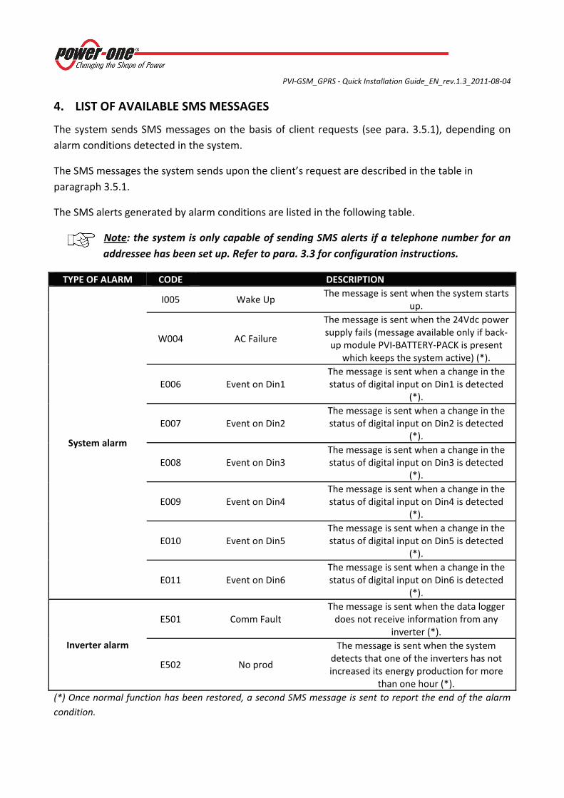
4. LIST OF AVAILABLE SMS MESSAGES
The system sends SMS messages on the basis of client requests (see para. 3.5.1), depending on alarm conditions detected in the system.
The SMS messages the system sends upon the client’s request are described in the table in paragraph 3.5.1.
The SMS alerts generated by alarm conditions are listed in the following table.
Note: the system is only capable of sending SMS alerts if a telephone number for an addressee has been set up. Refer to para. 3.3 for configuration instructions.
TYPE OF ALARM CODE DESCRIPTION
System alarm
I005 Wake Up The message is sent when the system starts
up.
W004 AC Failure
The message is sent when the 24Vdc power supply fails (message available only if back‐up module PVI‐BATTERY‐PACK is present
which keeps the system active) (*).
E006 Event on Din1 The message is sent when a change in the status of digital input on Din1 is detected
(*).
E007 Event on Din2 The message is sent when a change in the status of digital input on Din2 is detected
(*).
E008 Event on Din3 The message is sent when a change in the status of digital input on Din3 is detected
(*).
E009 Event on Din4 The message is sent when a change in the status of digital input on Din4 is detected
(*).
E010 Event on Din5 The message is sent when a change in the status of digital input on Din5 is detected
(*).
E011 Event on Din6 The message is sent when a change in the status of digital input on Din6 is detected
(*).
Inverter alarm
E501 Comm Fault The message is sent when the data logger does not receive information from any
inverter (*).
E502 No prod
The message is sent when the system detects that one of the inverters has not increased its energy production for more
than one hour (*). (*) Once normal function has been restored, a second SMS message is sent to report the end of the alarm condition.
PVI‐GSM_GPRS ‐ Quick Installation Guide_EN_rev.1.3_2011‐08‐04
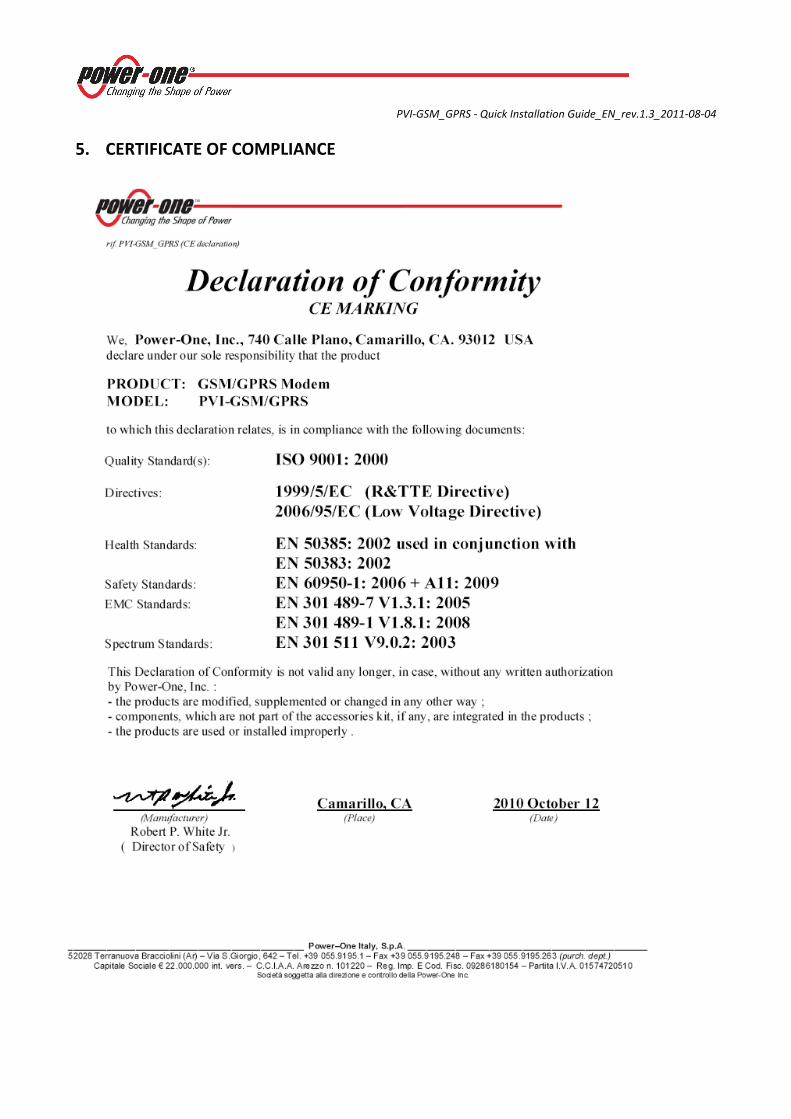
5. CERTIFICATE OF COMPLIANCE