Embed Size (px)
Citation preview
D I R E C T H E A LT H C A R E G R O U P. C O M
QUATTRO® AcuteQUATTRO® PlusUser Manual

Q U A T T R O ® A C U T E & Q U A T T R O ® P L U S
D I R E C T H E A LT H C A R E G R O U P. C O M
Page
1. Explanation of Labels Symbols and Statements ................................................................. 2
2. Introduction ....................................................................................................................... 3
3. Important Information ........................................................................................................ 3Intended Use ................................................................................................................... 3Intended Environments .................................................................................................... 3Contraindications for Use ................................................................................................. 3General Warnings, Cautions and Information .................................................................... 3
4. Installation Guidelines ........................................................................................................ 4Installing Mattresses ........................................................................................................ 4Installing Cushions ........................................................................................................... 5
5. Operation Guidelines .......................................................................................................... 6Operating Controls ........................................................................................................... 6Setting / Changing Power Unit Display Languages ........................................................... 7CPR Facility ..................................................................................................................... 7Patient Transport Facility .................................................................................................. 8NFC (RFID) ....................................................................................................................... 8Additional Operation Information ...................................................................................... 8Max. Patient Weight / Max. Load Guidelines ..................................................................... 8
6. Care and Maintenance ....................................................................................................... 8Mattress - Exterior Components ...................................................................................... 8Mattress - Interior Components ....................................................................................... 9Power Unit ....................................................................................................................... 9Servicing ......................................................................................................................... 9Transport and Storage ................................................................................................... 10Operational Conditions ................................................................................................... 10Transportation of Mattress System................................................................................. 10
7. Fault Finding .................................................................................................................... 10
8. Technical Specifications ................................................................................................... 11
Contents
D I R E C T H E A LT H C A R E G R O U P. C O M 1
U S E R M A N U A L
D I R E C T H E A LT H C A R E G R O U P. C O M
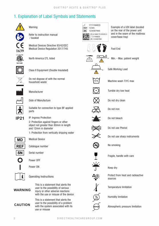
Example of a UDI label (located on the rear of the power unit and in the seam of the mattress cover/base tray)
Foot End
Min. - Max. patient weight
Safe Working Load
Machine wash 73oC max
Tumble dry low heat
Do not dry clean
Do not iron
Do not bleach
Do not use Phenol
Do not use sharp instruments
No smoking
Fragile, handle with care
Keep dry
Protect from heat and radioactive sources
Temperature limitation
Humidity limitation
Atmospheric pressure limitation
Warning
Refer to instruction manual / booklet
Medical Devices Directive 93/42/EECMedical Device Regulation 2017/745
North America ETL listed
Class II Equipment (Double Insulated)
Do not dispose of with the normal household waste
Manufacturer
Date of Manufacture
Suitable for connection to type BF applied parts
IP: Ingress Protection
2: Protection against fingers or other object not greater than 80mm in length and 12mm in diameter
1: Protection from vertically dripping water
Medical Device
Catalogue number
Serial number
Power OFF
Power ON
Operating Instructions
This is a statement that alerts the user to the possibility of serious injury or other adverse reactions with the use or misuse of the device
This is a statement that alerts the user to the possibility of a problem with the system associated with its use or misuse
123451234567890
YYYYMMDD
0 5060178 XXXXX XYYMMDD1234567890
IP21
WARNING
CAUTION
DECONTAMINATIONGUIDELINES -
REFER TO USER MANUAL FOR MORE INFORMATION200 Kg
200 Kg
DECONTAMINATIONGUIDELINES -
REFER TO USER MANUAL FOR MORE INFORMATION200 Kg
200 Kg
DECONTAMINATIONGUIDELINES -
REFER TO USER MANUAL FOR MORE INFORMATION200 Kg
200 Kg
DECONTAMINATIONGUIDELINES -
REFER TO USER MANUAL FOR MORE INFORMATION200 Kg
200 Kg
1. Explanation of Label Symbols and Statements
2
Q U A T T R O ® A C U T E & Q U A T T R O ® P L U S
73 250kg
73 250kg
73 250kg
73 250kg
73 250kg
73 250kg
2. Introduction
Thank you for choosing to use a QUATTRO active support surface, designed to reduce the risk of pressure related tissue injury via an active therapy alternating air pressure cycle.
3. Important Information
3.1 Intended UseQUATTRO active support surfaces are designed to reduce the risk of pressure related tissue injury in patients who are identified as being at an elevated risk of pressure ulceration and / or to help manage patients with existing pressure related tissue injury.
3.2 Intended EnvironmentsThe system is intended to be used in the following environments:- - Hospital - Professional Healthcare facilities - Home Healthcare
and for the following scenarios:- - Bed Mattress Replacement (replaces an existing mattress)
3.3 Contraindications for UseActive support surfaces should not be used for patients with unstable fractures, gross oedema, burns or an intolerance to motion.
3.4 General Warnings, Cautions and Information• There are no special skills required to operate the system.• The medical professional is responsible for applying his/her best medical judgment when using this system.• Select correct setting for therapy required. Care should be taken not to accidently change pressures once set as
the efficiency of the therapy may be reduced. This could also be caused by pets, pests or children.• The electricity supply is of the type indicated on the power unit• Check the mains power cord is free from damage and is positioned so as not to cause an obstruction, or injury,
e.g. strangulation.• Ensure the mains power cord or power unit cannot become trapped or crushed, e.g. via raising or lowering of bed
or bed rails or any other moving object.• The power unit must only be used with a suitable approved cord and plug set as supplied by Direct Healthcare
Group. • Do not use in the presence of flammable anaesthetics.• Suitable for continuous use.• To disconnect the power unit from the mains supply remove the mains power cord from the mains outlet wall
socket.• Do not position the power unit in such a way that makes it difficult to disconnect the mains power cord from the
device or the mains outlet.• Do not position the power unit in such a way that makes it difficult to disconnect the mattress from the power unit.• Do not place device on or near a heat source. • Do not use with hot water bottles or electric blankets.• The materials used in the manufacture of all components of the system comply with the required fire safety
regulations. • Direct Healthcare Group advise against smoking whilst the system is in use, to prevent the accidental secondary
ignition of associated items which may be flammable, such as bed linen.• Do not allow sharp objects to penetrate the mattress material.• WARNING: No modification of this equipment is allowed.• Do not store in damp conditions.
D I R E C T H E A LT H C A R E G R O U P. C O M 3
U S E R M A N U A L
• Do not use in an oxygen enriched environment. • Do not use in an outdoor environment.• No part of the medical device should be serviced while it is in use by the patient.• The medical equipment requires 5 hours to warm from the minimum storage temperature before it is ready for its intended
use.• The medical equipment requires 1 hour to cool from the maximum storage temperature before it is ready for its intended
use.• Intended for use in hospital, professional healthcare facility and home healthcare environments.• The power unit is intended to be hung over the footboard of a bed.• Wireless equipment such as mobile phones should be kept at least 1 foot or 0.3 metres away from the equipment.• Do not connect the power unit or mattress to any other medical device or equipment. • Risk of fire if incorrect fuse used.• The mattress and power unit should be cleaned between patient use, please refer to Care and Maintenance section for
all warnings and cautions.• Not suitable for sterilisation.• The mattress must be properly set up as directed.• Check periodically to ensure patient support and comfort, adjusting the COMFORT CONTROL setting if desired.• All hoses must be free of kinks, twists, properly connected and positioned so as not to cause an obstruction or injury.• In order for the alternating air pressure mattress/cushion to operate effectively, please avoid placing objects on the surface
that may obstruct the movement of air between the cells. For the same reason, please discourage people from sitting on the edge or on the end of the mattress whilst it is in use.
• Do not use abrasive cleaners, phenol disinfectants, solvents or alcohol-based cleansers, e.g. Dettol, Phenicol, Hibiscrub, Clearsol, Stericol, Hycoline, as these may destroy the cover materials (* see Care and Maintenance on page 9).
• The system is used as part of a pressure ulcer prevention and/or management program, not solely relied upon for this purpose.
• It should be noted that the use of a cushion will increase the patient’s seated height by approximately 5cm, and care should be taken to ensure the patient’s comfort and security regarding height of foot and arm rests.
• The above warnings, cautions and any safety considerations should be observed on a routine and regular basis, not only upon installation.
4. Installation Guidelines
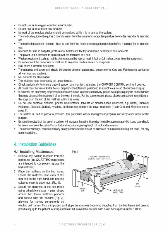
4.1 Installing Mattresses1. Remove any existing mattress from the
bed frame (the QUATTRO mattresses are intended to completely replace the bed mattress).
2. Place the mattress on the bed frame. Ensure the mattress hose exits at the foot end on the right hand side and the coloured cover is uppermost (Fig. 1).
3. Secure the mattress to the bed frame using adjustable straps - pass straps around bed frame mattress platform and secure with the buckles (Fig. 2), allowing for moving components on electric bed frames. This is important as it stops the mattress becoming detached from the bed frame and causing possible injury to the patient. A strap extension kit is available for use with divan beds (part number 11062).
Mattress (applied part)(mattress replacement shown)
CPRdevice
Mattress air supply hose
Power unit
Fig. 1
D I R E C T H E A LT H C A R E G R O U P. C O M4
Q U A T T R O ® A C U T E & Q U A T T R O ® P L U S
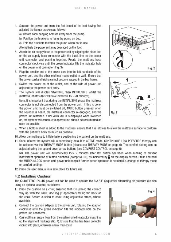
4. Suspend the power unit from the foot board of the bed having first adjusted the hanger brackets as follows:-
a) Rotate each hanging bracket away from the pump. b) Position the brackets to hang the pump on bed. c) Fold the brackets towards the pump when not in use. Alternatively the power unit may be placed on the floor.5. Attach the air supply hose to the power unit by aligning the black line
on the air supply hose connector with the black line on the power unit connector and pushing together. Rotate the mattress hose connector clockwise until the green indicator fills the indicator hole on the power unit connector (Fig. 3).
6. Plug the smaller end of the power cord into the left hand side of the power unit, and the other end into mains outlet in wall. Ensure that the power cord and tubing cannot become trapped in the bed frame.
7. Switch the power on at the outlet, and at the side of power unit adjacent to the power cord entry.
8. The system will display STARTING, then INITIALISING whilst the mattress inflates (this will take between 15 - 20 minutes).
Note: It is important that during the INITIALISING phase the mattress connector is not disconnected from the power unit. If this is done, the power unit must be switched off, MUTE button pressed when the sounder is heard, the mattress connector re-engaged, and the power unit restarted. If UNCALIBRATED is displayed when switched on, the system will continue to operate but should be recalibrated as soon as possible.
9. When a bottom sheet is added to the mattress, ensure that it is left lose to allow the mattress surface to conform with the patient’s body as much as possible.
10. Allow the mattress to inflate before positioning the patient on the mattress.11. Once inflated the system will automatically default to ACTIVE mode. CONTINUOUS LOW PRESSURE therapy can
be selected via the THERAPY MODE button (please see THERAPY MODE on page 6). The comfort setting can be adjusted using the up and down arrow buttons (see COMFORT CONTROL on page 6).
NB. The power unit will automatically lock 2 minutes after last button operation when running to prevent inadvertent operation of button functions (except MUTE), as indicated by on the display screen. Press and hold the MUTE/UNLOCK button until power unit beeps if further button operation is needed (i.e. change of therapy mode or comfort setting).
12. Place the user manual in a safe place for future use.
4.2 Installing CushionThe QUATTRO PLUS power unit can be used to operate the B.A.S.E. Sequential alternating air pressure cushion using an optional adaptor, as follows:-1. Place the cushion on a chair, ensuring that it is placed the correct
way up with the BACK labelling (if applicable) facing the back of the chair. Secure cushion to chair using adjustable straps, where available.
2. Connect the cushion adaptor to the power unit, rotating the adaptor clockwise until the green indicator fills the indicator hole on the power unit connector.
3. Connect the air supply hose from the cushion onto the adaptor, matching up the alignment markings (Fig. 4). Ensure that this has been correctly clicked into place, otherwise a leak may occur.
Fig. 2
Fig. 3
Fig. 4
D I R E C T H E A LT H C A R E G R O U P. C O M 5
U S E R M A N U A L
4. Attach the power cord, plug into the mains outlet and switch the power on at the side of power unit adjacent to the power cord entry.
5. Once inflated (approx. 5 minutes) increase the comfort control setting to SEATED using the UP arrow button.
NB. If using the power unit from an operating mattress system, first press the MAX. INFLATE button to fully inflate the mattress, then rotate the air supply hose connector anti-clockwise and detach from the power unit to seal the air within the mattress to leave it fully inflated. To reconnect the mattress to the power unit after using the cushion, switch off the power unit and disconnect the cushion adaptor. Re-connect the mattress air supply tubing to the power unit, and switch on the power unit (operation will automatically default to ACTIVE mode).NB. It should be noted that the use of an alternating air pressure cushion will increase the patient’s seated height by approximately 5cm, and care should be taken to ensure the patient’s comfort and security regarding height of foot and arm rests.
5. Operation Guidelines
5.1 Operation ControlsN.B. Before any operation buttons will function (except MUTE), the power unit must be unlocked** - press and hold the MUTE/UNLOCK button until the power unit beeps and the lock symbol clears from the display screen.
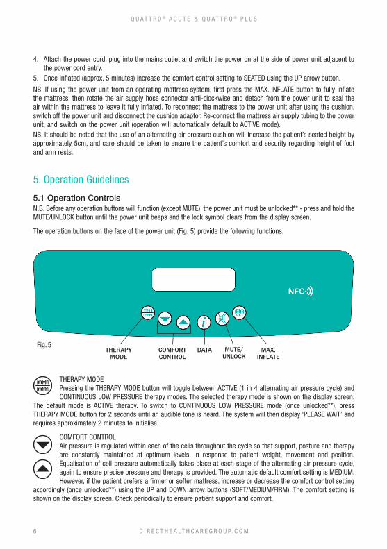
The operation buttons on the face of the power unit (Fig. 5) provide the following functions.
THERAPY MODEPressing the THERAPY MODE button will toggle between ACTIVE (1 in 4 alternating air pressure cycle) and CONTINUOUS LOW PRESSURE therapy modes. The selected therapy mode is shown on the display screen.
The default mode is ACTIVE therapy. To switch to CONTINUOUS LOW PRESSURE mode (once unlocked**), press THERAPY MODE button for 2 seconds until an audible tone is heard. The system will then display ‘PLEASE WAIT’ and requires approximately 2 minutes to initialise.
COMFORT CONTROLAir pressure is regulated within each of the cells throughout the cycle so that support, posture and therapy are constantly maintained at optimum levels, in response to patient weight, movement and position. Equalisation of cell pressure automatically takes place at each stage of the alternating air pressure cycle, again to ensure precise pressure and therapy is provided. The automatic default comfort setting is MEDIUM. However, if the patient prefers a firmer or softer mattress, increase or decrease the comfort control setting
accordingly (once unlocked**) using the UP and DOWN arrow buttons (SOFT/MEDIUM/FIRM). The comfort setting is shown on the display screen. Check periodically to ensure patient support and comfort.
Fig. 5THERAPY
MODECOMFORT CONTROL
DATA MUTE/UNLOCK
MAX. INFLATE
D I R E C T H E A LT H C A R E G R O U P. C O M6
Q U A T T R O ® A C U T E & Q U A T T R O ® P L U S
DATA (Used for accessing information only, does not affect mode of operation)Pressing the DATA button at any time switches the display into DATA mode. Use the up and down arrow buttons to scroll through the product data and user information set. Pressing the DATA button again returns
the display to the previous mode.
**MUTE/UNLOCKPress to silence the sounder and to clear the message from the display screen. The power unit will automatically lock 2 minutes after the last button operation when running to prevent the inadvertent
operation of button functions (except MUTE), as indicated by on the display screen. Press and hold the MUTE/UNLOCK button until the power unit beeps if further button operation is needed (i.e. comfort setting). The power unit will lock again 2 minutes after the last button operation.
NB. After power failure/switching the power off, pressing MUTE cancels the system’s previous settings. When power returns the default setting of ACTIVE mode, MEDIUM comfort setting is invoked. (Note that previous settings are automatically cancelled if the duration between switch off and switch on is greater than 12 seconds. If power returns before a period of 12 seconds has passed and the MUTE button has not been pressed, the system will return to the previous mode of operation.)
MAX. INFLATENecessary for some nursing procedures, the MAX INFLATE mode inflates the mattress to maximum static pressure for a period of 15 minutes. After pressing the MAX INFLATE button (once unlocked**) to inflate
mattress, the system displays ‘PLEASE WAIT’ followed by ‘READY’ and a 5 second audible tone when maximum pressure is achieved and ‘MAX INFLATE’ is shown on the display screen. After 15 minutes the system automatically returns to the ACTIVE mode of operation.
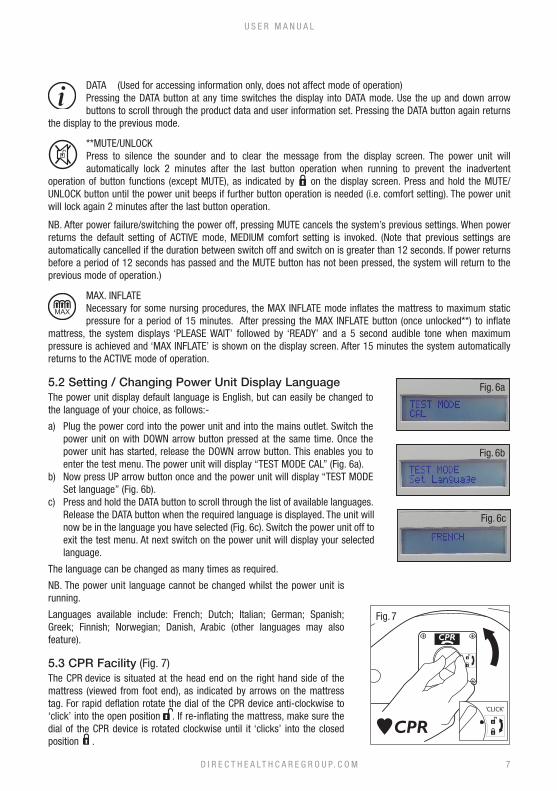
5.2 Setting / Changing Power Unit Display LanguageThe power unit display default language is English, but can easily be changed to the language of your choice, as follows:-
a) Plug the power cord into the power unit and into the mains outlet. Switch the power unit on with DOWN arrow button pressed at the same time. Once the power unit has started, release the DOWN arrow button. This enables you to enter the test menu. The power unit will display “TEST MODE CAL” (Fig. 6a).
b) Now press UP arrow button once and the power unit will display “TEST MODE Set language” (Fig. 6b).
c) Press and hold the DATA button to scroll through the list of available languages. Release the DATA button when the required language is displayed. The unit will now be in the language you have selected (Fig. 6c). Switch the power unit off to exit the test menu. At next switch on the power unit will display your selected language.
The language can be changed as many times as required.
NB. The power unit language cannot be changed whilst the power unit is running.
Languages available include: French; Dutch; Italian; German; Spanish; Greek; Finnish; Norwegian; Danish, Arabic (other languages may also feature).
5.3 CPR Facility (Fig. 7)The CPR device is situated at the head end on the right hand side of the mattress (viewed from foot end), as indicated by arrows on the mattress tag. For rapid deflation rotate the dial of the CPR device anti-clockwise to ‘click’ into the open position . If re-inflating the mattress, make sure the dial of the CPR device is rotated clockwise until it ‘clicks’ into the closed position .
Fig. 6a
Fig. 6b
Fig. 6c
Fig. 7
D I R E C T H E A LT H C A R E G R O U P. C O M 7
U S E R M A N U A L
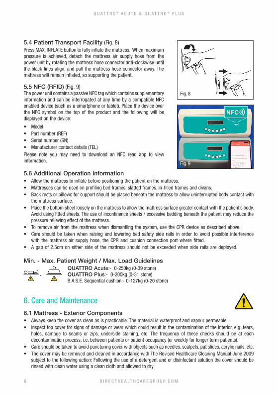
5.4 Patient Transport Facility (Fig. 8)Press MAX. INFLATE button to fully inflate the mattress. When maximum pressure is achieved, detach the mattress air supply hose from the power unit by rotating the mattress hose connector anti-clockwise until the black lines align, and pull the mattress hose connector away. The mattress will remain inflated, so supporting the patient.
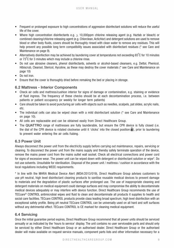
5.5 NFC (RFID) (Fig. 9)The power unit contains a passive NFC tag which contains supplementary information and can be interrogated at any time by a compatible NFC enabled device (such as a smartphone or tablet). Place the device over the NFC symbol on the top of the product and the following will be displayed on the device:
• Model• Part number (REF)• Serial number (SN)• Manufacturer contact details (TEL)Please note you may need to download an NFC read app to view information.
5.6 Additional Operation Information• Allow the mattress to inflate before positioning the patient on the mattress.• Mattresses can be used on profiling bed frames, slatted frames, in-filled frames and divans.• Back rests or pillows for support should be placed beneath the mattress to allow uninterrupted body contact with
the mattress surface.• Place the bottom sheet loosely on the mattress to allow the mattress surface greater contact with the patient’s body.
Avoid using fitted sheets. The use of incontinence sheets / excessive bedding beneath the patient may reduce the pressure relieving effect of the mattress.
• To remove air from the mattress when dismantling the system, use the CPR device as described above.• Care should be taken when raising and lowering bed safety side rails in order to avoid possible interference
with the mattress air supply hose, the CPR and cushion connection port where fitted. • A gap of 2.5cm on either side of the mattress should not be exceeded when side rails are deployed.
Min. - Max. Patient Weight / Max. Load GuidelinesQUATTRO Acute:- 0-250kg (0-39 stone) QUATTRO Plus:- 0-200kg (0-31 stone)B.A.S.E. Sequential cushion:- 0-127kg (0-20 stone)
6. Care and Maintenance
6.1 Mattress - Exterior Components• Always keep the cover as clean as is practicable. The material is waterproof and vapour permeable.• Inspect top cover for signs of damage or wear which could result in the contamination of the interior, e.g. tears,
holes, damage to seams or zips, underside staining, etc. The frequency of these checks should be at each decontamination process, i.e. between patients or patient occupancy (or weekly for longer term patients).
• Care should be taken to avoid puncturing cover with objects such as needles, scalpels, pat slides, acrylic nails, etc.• The cover may be removed and cleaned in accordance with The Revised Healthcare Cleaning Manual June 2009
subject to the following action: Following the use of a detergent and or disinfectant solution the cover should be rinsed with clean water using a clean cloth and allowed to dry.
Fig. 8
D I R E C T H E A LT H C A R E G R O U P. C O M8
Q U A T T R O ® A C U T E & Q U A T T R O ® P L U S
Fig. 9
• Frequent or prolonged exposure to high concentrations of aggressive disinfectant solutions will reduce the useful life of the cover.
• Where high concentration disinfectants e.g. > 10,000ppm chlorine releasing agent (e.g. Haztab or bleach) or combined cleaning/chlorine releasing agent (e.g. Chlorclean, Actichlor) and detergent solutions are used to remove blood or other body fluids, covers should be thoroughly rinsed with clean water to remove any residues. This will help prevent any possible long term compatibility issues associated with disinfectant residues (* see Care and Maintenance on page 9).
• Alternatively disinfection may be achieved by laundering cover at temperatures not exceeding 650C for 10 minutes
or 730C for 3 minutes which may include a chlorine rinse.
• Do not use abrasive cleaners, phenol disinfectants, solvents or alcohol-based cleansers, e.g. Dettol, Phenicol, Hibiscrub, Clearsol, Stericol, Hycoline, as these may destroy the cover materials (* see Care and Maintenance on page 10)
• Do not iron.• Ensure that the cover is thoroughly dried before remaking the bed or placing in storage.
6.2 Mattress - Interior Components• Check air cells and mattress/cushion interior for signs of damage or contamination, e.g. staining or evidence
of fluid ingress. The frequency of these checks should be at each decontamination process, i.e. between patients or patient occupancy (or weekly for longer term patients)
• Care should be taken to avoid puncturing air cells with objects such as needles, scalpels, pat slides, acrylic nails, etc.
• The individual cells can also be wiped clean with a mild disinfectant solution (* see Care and Maintenance on page 10).
• All cells are replaceable and can be obtained easily from Direct Healthcare Group.• The QUATTRO range of mattresses are fully launderable, but ensure the CPR device is fully closed (i.e.
the dial of the CPR device is rotated clockwise until it ‘clicks’ into the closed position ), prior to laundering to prevent water entering the air cells / tubing.
6.3 Power UnitAlways disconnect the power unit from the electricity supply before carrying out maintenance, repairs, servicing or cleaning. To disconnect the power unit from the mains supply and thereby safely terminate operation of the device, remove the mains power cord from the mains outlet wall socket. Check all electrical connections and power cord for signs of excessive wear. The power unit can be wiped down with detergent or disinfectant solution or wipe*. Do not use solvents. Unsuitable for sterilisation. Disposal of the power unit / mattress / cushion in accordance with the local regulations including WEEE requirements.
* In line with the MHRA Medical Device Alert (MDA/2013/019), Direct Healthcare Group advises customers to use pH neutral, high level disinfectant cleaning products to sanitise reusable medical devices to prevent damage to materials and the degradation of plastic surfaces after prolonged use. The use of inappropriate cleaning and detergent materials on medical equipment could damage surfaces and may compromise the ability to decontaminate medical devices adequately or may interfere with device function. Direct Healthcare Group recommends the use of TECcare® CONTROL antimicrobial wipes and fluid to clean and decontaminate all products it supplies to health and social care facilities. TECcare CONTROL products provide class leading broad spectrum, high level disinfection with an exceptional safety profile. Being pH neutral TECcare CONTROL can be universally used on all hard and soft surfaces without any detrimental effect. TECcare CONTROL is CE marked for cleaning medical equipment.
6.4 ServicingOnce the initial guarantee period expires, Direct Healthcare Group recommend that all power units should be serviced annually or as indicated by the ‘hours to service’ display. The unit contains no user serviceable parts and should only be serviced by either Direct Healthcare Group or an authorised dealer. Direct Healthcare Group or the authorised dealer will make available on request service manuals, component parts lists and other information necessary for a
D I R E C T H E A LT H C A R E G R O U P. C O M 9
U S E R M A N U A L
competent electrical engineer to repair or service the system. For service, maintenance and any questions regarding this, please contact Direct Healthcare Group or an authorised dealer.
It is the customer’s responsibility to ensure the following prior to collection:• the system is cleaned of any obvious contaminants.• contamination status is documented.• assistance is given to Direct Healthcare Group personnel to bag the equipment if the mattress has been in a known
or suspected infectious environment.
6.5 Transport and StorageHandle with care. Please report instances of damage or impact to Direct Healthcare Group Service Department.–25 °C without relative humidity control; and+70 °C at a relative humidity up to 93 %, non-condensing.An atmospheric pressure range of 700 hPa to 1,060 hPa.Suitable for all standard modes of transport when in the correct packaging.
6.6 Operational ConditionsA temperature range of +5 °C to +40 °C;A relative humidity range of 15% to 93%, non-condensing; andOperational Atmospheric Pressure: 700 hPa to 1,060 hPaSuitable for pollution degree 2Operational altitude ≤ 2 000 mIP Rating: IP21 power unit only
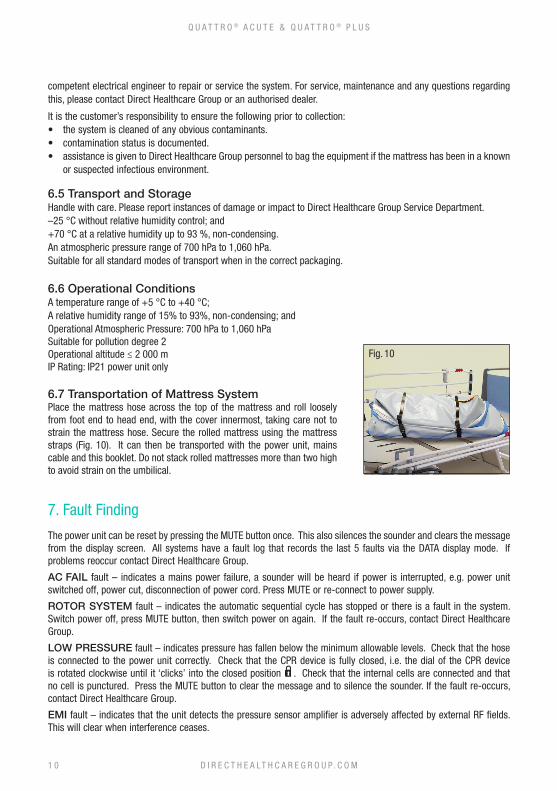
6.7 Transportation of Mattress SystemPlace the mattress hose across the top of the mattress and roll loosely from foot end to head end, with the cover innermost, taking care not to strain the mattress hose. Secure the rolled mattress using the mattress straps (Fig. 10). It can then be transported with the power unit, mains cable and this booklet. Do not stack rolled mattresses more than two high to avoid strain on the umbilical.
7. Fault Finding
The power unit can be reset by pressing the MUTE button once. This also silences the sounder and clears the message from the display screen. All systems have a fault log that records the last 5 faults via the DATA display mode. If problems reoccur contact Direct Healthcare Group.
AC FAIL fault – indicates a mains power failure, a sounder will be heard if power is interrupted, e.g. power unit switched off, power cut, disconnection of power cord. Press MUTE or re-connect to power supply.
ROTOR SYSTEM fault – indicates the automatic sequential cycle has stopped or there is a fault in the system. Switch power off, press MUTE button, then switch power on again. If the fault re-occurs, contact Direct Healthcare Group.
LOW PRESSURE fault – indicates pressure has fallen below the minimum allowable levels. Check that the hose is connected to the power unit correctly. Check that the CPR device is fully closed, i.e. the dial of the CPR device is rotated clockwise until it ‘clicks’ into the closed position . Check that the internal cells are connected and that no cell is punctured. Press the MUTE button to clear the message and to silence the sounder. If the fault re-occurs, contact Direct Healthcare Group.
EMI fault – indicates that the unit detects the pressure sensor amplifier is adversely affected by external RF fields. This will clear when interference ceases.
Fig. 10
D I R E C T H E A LT H C A R E G R O U P. C O M1 0
Q U A T T R O ® A C U T E & Q U A T T R O ® P L U S
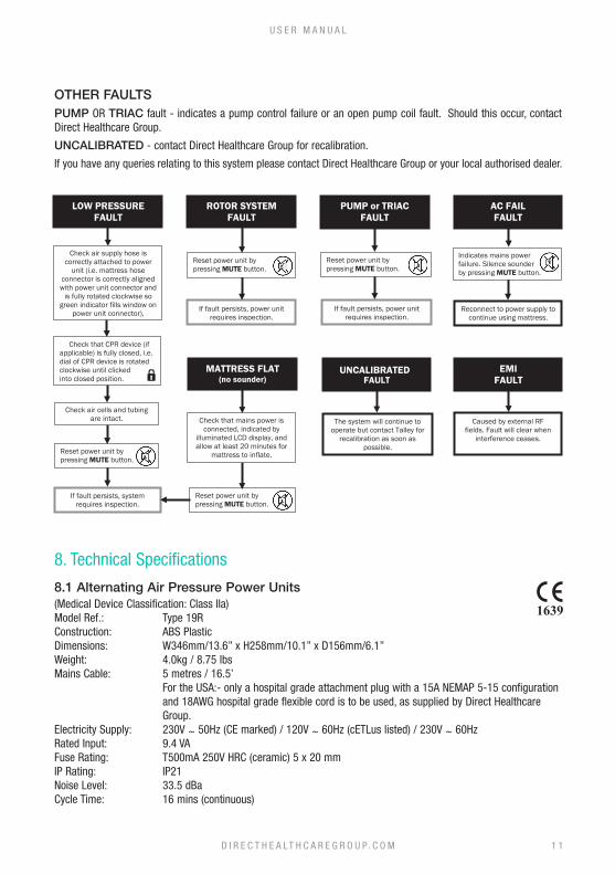
OTHER FAULTSPUMP OR TRIAC fault - indicates a pump control failure or an open pump coil fault. Should this occur, contact Direct Healthcare Group.
UNCALIBRATED - contact Direct Healthcare Group for recalibration.
If you have any queries relating to this system please contact Direct Healthcare Group or your local authorised dealer.
8. Technical Specifications
8.1 Alternating Air Pressure Power Units(Medical Device Classification: Class IIa)Model Ref.: Type 19RConstruction: ABS PlasticDimensions: W346mm/13.6” x H258mm/10.1” x D156mm/6.1”Weight: 4.0kg / 8.75 lbsMains Cable: 5 metres / 16.5’ For the USA:- only a hospital grade attachment plug with a 15A NEMAP 5-15 configuration
and 18AWG hospital grade flexible cord is to be used, as supplied by Direct Healthcare Group.
Electricity Supply: 230V ~ 50Hz (CE marked) / 120V ~ 60Hz (cETLus listed) / 230V ~ 60HzRated Input: 9.4 VAFuse Rating: T500mA 250V HRC (ceramic) 5 x 20 mmIP Rating: IP21Noise Level: 33.5 dBaCycle Time: 16 mins (continuous)
If fault persists, power unit requires inspection.
Reconnect to power supply to continue using mattress.
PUMP or TRIAC FAULT
AC FAIL FAULT
LOW PRESSURE FAULT
Indicates mains power failure. Silence sounder by pressing MUTE button.
Check air supply hose is correctly attached to power
unit (i.e. mattress hose connector is correctly aligned with power unit connector and
is fully rotated clockwise so green indicator fills window on
power unit connector). If fault persists, power unit requires inspection.
Reset power unit by pressing MUTE button.
If fault persists, system requires inspection.
Reset power unit by pressing MUTE button.
Reset power unit by pressing MUTE button.
EMI FAULT
Caused by external RF fields. Fault will clear when
interference ceases.
Check air cells and tubing are intact.
FAULT
Reset power unit by pressing MUTE button.
MATTRESS FLAT (no sounder)
Check that mains power is connected, indicated by
illuminated LCD display, and allow at least 20 minutes for
mattress to inflate.
UNCALIBRATED
The system will continue to operate but contact Talley for
recalibration as soon as possible.
Check that CPR device (if applicable) is fully closed, i.e. dial of CPR device is rotated clockwise until clicked into closed position.
ROTOR SYSTEM FAULT
D I R E C T H E A LT H C A R E G R O U P. C O M 1 1
U S E R M A N U A L
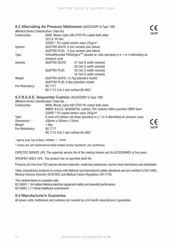
8.2 Alternating Air Pressure Mattresses (ACCESSORY to Type 19R)(Medical Device Classification: Class IIa)Construction: BASE: Woven nylon 940 DTEX PU coated both sides CELLS: PU film COVER 2: PU coated stretch nylon 255g/m2
Options: QUATTRO ACUTE: 6 size variants (see below) QUATTRO PLUS: 6 size variants (see below)Type: Orthodifferential TISSUEgard™ pleated air cells operating in a 1-in-4 alternating air
pressure cycleVariants: QUATTRO ACUTE: 27 Cell (3 width variants) 28 Cell (3 width variants) QUATTRO PLUS: 30 Cell (3 width variants) 32 Cell (3 width variants)Weight: QUATTRO ACUTE: 12.7kg (standard model) QUATTRO PLUS: 9.9kg (standard model)Fire Retardancy: BS 7177 BS 7175 Crib 5 test method BS 6807
8.3 B.A.S.E. Sequential Cushion (ACCESSORY to Type 19R)(Medical Device Classification: Class IIa)Construction: BASE: Woven nylon 940 DTEX PU coated both sides INNER: B.A.S.E. SEQUENTIAL cushion: PVC bellows within punched CMFR foam COVER 2: PU coated stretch nylon 255g/m2
Type: 8 rows of 6 bellow cell strips operating in a 1-in-4 alternating air pressure cycleDimensions 1 : 430mm x 430mm x 70mmWeight: 1.9kgFire Retardancy: BS 7177 BS 7175 Crib 5 test method BS 6807
1 approx.max. top surface, inflated +/- 15mm2 Covers are anti-bacterial/microbial treated (active ingredient: zinc pyrithione).
EXPECTED SERVICE LIFE: The expected service life of the medical device and its ACCESSORIES is five years.
SPECIFIED SHELF LIFE: The product has no specified shelf life.
Products are free from TSE species derived materials, medicinal substances, human blood derivatives and phthalates.
Talley manufacture products to comply with National and International safety standards and are certified to ISO13485, Medical Devices Directive 93/42/EEC and Medical Device Regulation 2017/745.
This medical device is compliant with:IEC 60601.1 3rd edition Medical electrical equipment safety and essential performanceIEC 60601.1.11 Home healthcare environment
8.4 Manufacturer’s GuaranteeAll power units, mattresses and cushions are covered by a 24 month manufacturer’s guarantee.
D I R E C T H E A LT H C A R E G R O U P. C O M1 2
Q U A T T R O ® A C U T E & Q U A T T R O ® P L U S
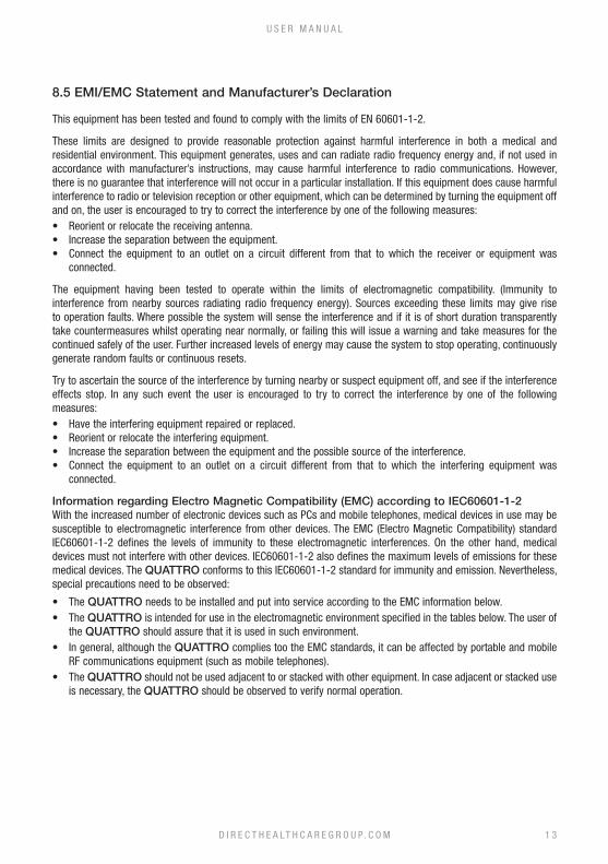
8.5 EMI/EMC Statement and Manufacturer’s Declaration
This equipment has been tested and found to comply with the limits of EN 60601-1-2.
These limits are designed to provide reasonable protection against harmful interference in both a medical and residential environment. This equipment generates, uses and can radiate radio frequency energy and, if not used in accordance with manufacturer’s instructions, may cause harmful interference to radio communications. However, there is no guarantee that interference will not occur in a particular installation. If this equipment does cause harmful interference to radio or television reception or other equipment, which can be determined by turning the equipment off and on, the user is encouraged to try to correct the interference by one of the following measures:• Reorient or relocate the receiving antenna.• Increase the separation between the equipment.• Connect the equipment to an outlet on a circuit different from that to which the receiver or equipment was
connected.
The equipment having been tested to operate within the limits of electromagnetic compatibility. (Immunity to interference from nearby sources radiating radio frequency energy). Sources exceeding these limits may give rise to operation faults. Where possible the system will sense the interference and if it is of short duration transparently take countermeasures whilst operating near normally, or failing this will issue a warning and take measures for the continued safely of the user. Further increased levels of energy may cause the system to stop operating, continuously generate random faults or continuous resets.
Try to ascertain the source of the interference by turning nearby or suspect equipment off, and see if the interference effects stop. In any such event the user is encouraged to try to correct the interference by one of the following measures:• Have the interfering equipment repaired or replaced.• Reorient or relocate the interfering equipment.• Increase the separation between the equipment and the possible source of the interference.• Connect the equipment to an outlet on a circuit different from that to which the interfering equipment was
connected.
Information regarding Electro Magnetic Compatibility (EMC) according to IEC60601-1-2With the increased number of electronic devices such as PCs and mobile telephones, medical devices in use may be susceptible to electromagnetic interference from other devices. The EMC (Electro Magnetic Compatibility) standard IEC60601-1-2 defines the levels of immunity to these electromagnetic interferences. On the other hand, medical devices must not interfere with other devices. IEC60601-1-2 also defines the maximum levels of emissions for these medical devices. The QUATTRO conforms to this IEC60601-1-2 standard for immunity and emission. Nevertheless, special precautions need to be observed:
• The QUATTRO needs to be installed and put into service according to the EMC information below.• The QUATTRO is intended for use in the electromagnetic environment specified in the tables below. The user of
the QUATTRO should assure that it is used in such environment.• In general, although the QUATTRO complies too the EMC standards, it can be affected by portable and mobile
RF communications equipment (such as mobile telephones).• The QUATTRO should not be used adjacent to or stacked with other equipment. In case adjacent or stacked use
is necessary, the QUATTRO should be observed to verify normal operation.
D I R E C T H E A LT H C A R E G R O U P. C O M 1 3
U S E R M A N U A L
D I R E C T H E A LT H C A R E G R O U P. C O M1 4
Q U A T T R O ® A C U T E & Q U A T T R O ® P L U S
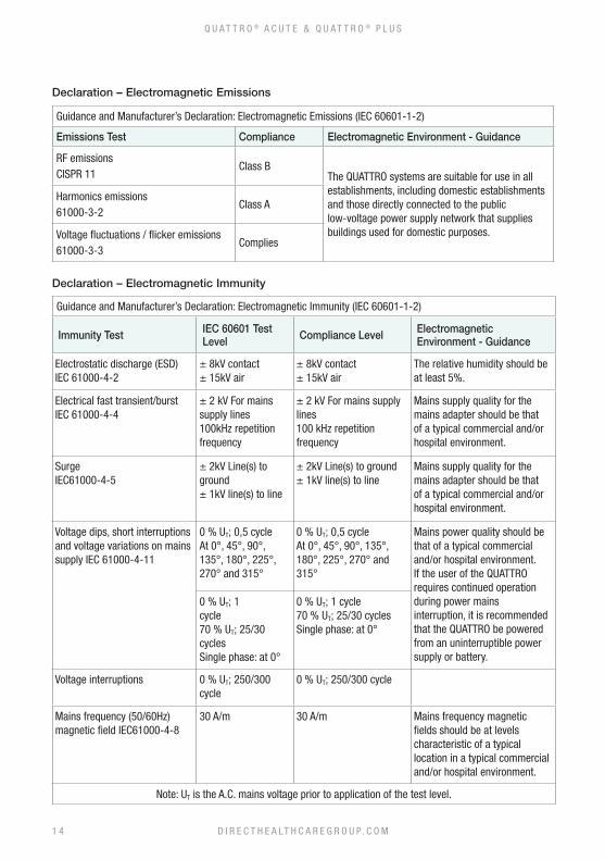
Declaration – Electromagnetic Emissions
Declaration – Electromagnetic Immunity
Guidance and Manufacturer’s Declaration: Electromagnetic Immunity (IEC 60601-1-2)
Immunity Test IEC 60601 Test Level Compliance Level Electromagnetic
Environment - Guidance
Electrostatic discharge (ESD) IEC 61000-4-2
± 8kV contact± 15kV air
± 8kV contact± 15kV air
The relative humidity should be at least 5%.
Electrical fast transient/burst IEC 61000-4-4
± 2 kV For mains supply lines100kHz repetition frequency
± 2 kV For mains supply lines100 kHz repetition frequency
Mains supply quality for the mains adapter should be that of a typical commercial and/or hospital environment.
SurgeIEC61000-4-5
± 2kV Line(s) to ground± 1kV line(s) to line
± 2kV Line(s) to ground± 1kV line(s) to line
Mains supply quality for the mains adapter should be that of a typical commercial and/or hospital environment.
Voltage dips, short interruptions and voltage variations on mains supply IEC 61000-4-11
0 % UT; 0,5 cycle At 0°, 45°, 90°, 135°, 180°, 225°, 270° and 315°
0 % UT; 0,5 cycle At 0°, 45°, 90°, 135°, 180°, 225°, 270° and 315°
Mains power quality should be that of a typical commercial and/or hospital environment. If the user of the QUATTRO requires continued operation during power mains interruption, it is recommended that the QUATTRO be powered from an uninterruptible power supply or battery.
0 % UT; 1 cycle 70 % UT; 25/30 cyclesSingle phase: at 0°
0 % UT; 1 cycle 70 % UT; 25/30 cyclesSingle phase: at 0°
Voltage interruptions 0 % UT; 250/300 cycle
0 % UT; 250/300 cycle
Mains frequency (50/60Hz) magnetic field IEC61000-4-8
30 A/m 30 A/m Mains frequency magnetic fields should be at levels characteristic of a typical location in a typical commercial and/or hospital environment.
Note: UT is the A.C. mains voltage prior to application of the test level.
Guidance and Manufacturer’s Declaration: Electromagnetic Emissions (IEC 60601-1-2)
Emissions Test Compliance Electromagnetic Environment - Guidance
RF emissionsCISPR 11
Class BThe QUATTRO systems are suitable for use in all establishments, including domestic establishments and those directly connected to the public low-voltage power supply network that supplies buildings used for domestic purposes.
Harmonics emissions61000-3-2
Class A
Voltage fluctuations / flicker emissions61000-3-3
Complies
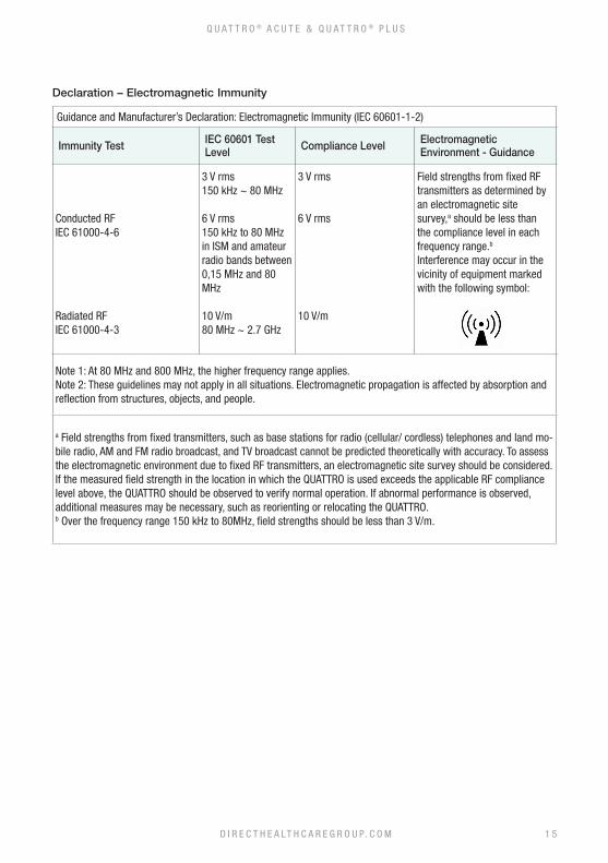
Guidance and Manufacturer’s Declaration: Electromagnetic Immunity (IEC 60601-1-2)
Immunity Test IEC 60601 Test Level Compliance Level Electromagnetic
Environment - Guidance
Conducted RFIEC 61000-4-6
Radiated RFIEC 61000-4-3
3 V rms150 kHz ~ 80 MHz
6 V rms150 kHz to 80 MHzin ISM and amateur radio bands between 0,15 MHz and 80 MHz
10 V/m80 MHz ~ 2.7 GHz
3 V rms
6 V rms
10 V/m
Field strengths from fixed RF transmitters as determined by an electromagnetic sitesurvey,a should be less than the compliance level in each frequency range.b
Interference may occur in the vicinity of equipment marked with the following symbol:
Note 1: At 80 MHz and 800 MHz, the higher frequency range applies.Note 2: These guidelines may not apply in all situations. Electromagnetic propagation is affected by absorption and reflection from structures, objects, and people.
a Field strengths from fixed transmitters, such as base stations for radio (cellular/ cordless) telephones and land mo-bile radio, AM and FM radio broadcast, and TV broadcast cannot be predicted theoretically with accuracy. To assess the electromagnetic environment due to fixed RF transmitters, an electromagnetic site survey should be considered. If the measured field strength in the location in which the QUATTRO is used exceeds the applicable RF compliance level above, the QUATTRO should be observed to verify normal operation. If abnormal performance is observed, additional measures may be necessary, such as reorienting or relocating the QUATTRO.b Over the frequency range 150 kHz to 80MHz, field strengths should be less than 3 V/m.
D I R E C T H E A LT H C A R E G R O U P. C O M
Q U A T T R O ® A C U T E & Q U A T T R O ® P L U S
Declaration – Electromagnetic Immunity
1 5
D I R E C T H E A LT H C A R E G R O U P. C O M1 6
Q U A T T R O ® A C U T E & Q U A T T R O ® P L U S
Every care has been taken to ensure that the information contained in this manual was correct at the time of going to press. However, Direct Healthcare Group reserves the right to modify the specification of any product without prior notice in line with a policy of continual product development. Information is available in alternative formats on request.
Our standard terms and conditions apply.

D I R E C T H E A LT H C A R E G R O U P. C O M
Q U A T T R O ® A C U T E & Q U A T T R O ® P L U S
Notes
1 7
Talley Group LtdPremier WayAbbey Park Industrial EstateRomsey SO51 9DQEngland
+44 (0) 1794 503500
EC REP Advena Ltd., Tower Business Centre2nd Flr., Tower Street, SwatarBKR 4013 Malta
Direct Healthcare GroupWithey Court, Western Industrial EstateCaerphilly, United KingdomCF83 1BF
T: +44 (0) 845 459 9831F: +44 (0) 845 459 9832E: [email protected]
Intelligent Pressure CareSpecialist SeatingRental & Service SolutionsSafe Moving & HandlingBathroom Safety Solutions
Part number: 11880 issue 1Date: April 2021
D I R E C T H E A LT H C A R E G R O U P. C O M