Embed Size (px)
Citation preview

www.kufatec.de
Kufatec GmbH & Co. KG • Dahlienstr. 15 • 23795 Bad Segeberg • e-mail: [email protected]
Version 1.07 (11.07.2018)
Installation instruction Complete set Active Sound
incl. Sound Booster
VW Amarok 2H

1
Contents
Disclaimer ................................................................................................................................................ 2 Copyright .................................................................................................................................................. 3 General advice ......................................................................................................................................... 3 Safety instructions .................................................................................................................................... 4 References of legal regulations for operation ........................................................................................... 4 Notes ........................................................................................................................................................ 5 Installation instructions ............................................................................................................................. 6 Software ................................................................................................................................................. 11

2
Disclaimer Dear Buyer, our cable harnesses are developed with the help of the circuit diagrams and wiring schemes of the particular vehicle producer and they are tested and adjusted to the original vehicle before the serial production. Therefore the integration into to the on-board electric and electronic system follows the information of the vehicle producers. Our installation instructions are consistent, in course of the necessary pre-understanding and the precision of the presentation in text and picture, with the staff usual in vehicle electrics / electronic and they have proven their value already hundredfold in practice. If during the installation of our products drench occur difficulties, so we are any time ready to provide you support by phone or E-Mail. Additionally we offer you to use the installation in our workshop in Bad Segeberg. The costs arising from the third parties assigned with the installation of our products, bears the Buyer. Only when it proves that there is a failure of our product we will compensate the evidenced costs of the assembly and the costs of the dismantling of the defective product, whereby we limit the cost reimbursement up to 110 EURO gross and we reserve our right to check the claimed defect in our workshop in Bad Segeberg. The costs of dispatch will be refunded in case of a justified claim. We made the experience that each professional workshop which is equipped with a necessary diagnosis devices, diagnosis software and the circuit diagrams of the producer, can find the possible defects in our products within a short period of time, so the assembly and disassembly including failure diagnosis, can take place in maximum 60 minutes. We also made the experience that many workshops are not able to cope with the producer’s circuit diagrams and cannot read the common wiring schemes, so for simplest installation labors several hours are calculated. You will understand that we neither take the risk to find a reliable workshop nor we finance the training for the workers of the workshop of your confidence. The costs that arise from the acquisition of the missing parts or replace for defective parts from another suppliers, we reimburse to the amount of the costs which would have arisen in case of subsequent delivery (saved expenditure). In this case according to the legal warranty law there would be no reimbursement right of any kind, as long as no deadline was set for the supplementary performance or a deadline for supplementary performance has not expired. So if you have any problems during the installation or operation of our products call us write us an E-Mail, send us the product or come to our workshop in Bad Segeberg with your vehicle. We are sure to find a solution for concern of every kind. Kind regards Your Kufatec GmbH & Co. KG Team

3
Copyright Our assembly and operation manuals, assembling diagrams and additional documentation in text or picture form are protected by law. Disclosure and distribution of this documentation through print or online media is permitted only after previous written acceptance from Kufatec GmbH & Co. KG.
General advice While developing this product, your personal safety combined with the best operating service, modern design and an up-to-date production technique was especially taken into account. Unfortunately, despite the utmost care injuries and/or damages might occur due to improper installation and/or use. Therefore please read with great care and completely this operating manual and store it appropriately! For your safety all our products pass through a 100% control check. We reserve the right to carry out technical changes which serve the improvement at any time. According to each article and purpose, it is sometimes necessary to check each country’s legal regulations before installing and starting the unit. In case of guarantee claims, the device has to be sent back to the seller in the original packaging with the attached bill of purchase and detailed defect‘s description. Please pay attention to the manufacturer‘s return requirements (RMA). The legal warranty directions are valid. The warranty claims as well as the operating permissions become invalid due to: a) unauthorized changes to the device or accessories which have not been approved or carried out by the manufacturer or its partners
b) opening the device‘s frame
c) self-made repairs on the device
d) improper use / operation
e) brute force to the device (drop, willful damage, accident etc.) During installation, please pay attention to all safety relevant and legal directions. The device has only to be installed by trained personnel or similarly qualified people. Please limit the failure search to ca. 0,5 hour for the mechanical resp. 1.0 hour for electric labors during the assembly or functioning problems. To avoid unnecessary additional expenses please send immediately an inquiry to our technical support using the Kufatec form (http://www.kufatec.de/shop/de/infocenter/). Please provide always the following information:
chassis number
part number of the add-on kit
exact description of the problem
already executed labor

4
Safety instructions The installation can be executed only by trained qualified personnel. Before the installation disconnect the power supply. Therefore cut off the battery from the vehicle electric system, follow the manufacturer’s specification.
• Never use bolts, screws and other fastening elements from car’s safety devices or steering wheel, brakes because it may influence your driving safety and cause accidents.
• Connect the device only to a 12V vehicle voltage with chassis ground to the car body. This unit cannot be used in large trucks or other vehicles which use a DC 24 V battery wiring system voltage.
• Avoid to install the device in places where it could hinder the safe driving or functional efficiency of the other units installed in the vehicle.
• This unit is only for the use with the following vehicles and model line; Only connections described within this instruction manual are allowed or required to use for installation.
• For damage impact caused by faulty installation, unsuitable connections or assembling in inappropriate vehicle types or models Kufatec GmbH &Co.KG assumes no liability.
• We advise you that these units process data out of the MOST protocol from the vehicle. During the assembly of this unit we as supplier have access to a specific model and we as producer don’t know the overall system you work with.
• Especially in case of changes within the same model line and the same model year we don’t guarantee the usability of our products. In case of the usability of our products with the manufacturer’s changes Kufatec GmbH assumes no liability.
• Kufatec GmbH assumes no liability that the assembly of the unit described in this manual is approved according the warranty regulations of the single car manufacturers. Please check your manufacturer’s conditions and warranty before you begin the installation.
• Kufatec GmbH reserves the right to change the device specification without further notice.
• Errors and changes excepted.
References of legal regulations for operation Use this unit in the intended domain only. If you use the unit in a foreign domain, if the unit is not installed properly, or if the unit will be reconstructed the operating permit and warranty will expire.

5
Notes
Note: At first please check if the sound generator can be installed at the described position. If there is no space please interrupt the installation and contact our technical support.Don't continue with this installation, until this issue is clarified.
Note: The use of a sound booster is not permitted without registration in the vehicle papers, in the area of the german StVZO. The noise emission of the vehicle is increased by this retrofit. The regulations of the StVZO must be observed. It is therefore recommended to ask for a specific registration option at the responsible TÜV/DEKRA office before retrofitting. Outside Germany, please observe the laws on vehicle licensing applicable in your country.

6
Installation instructions The following presentation shows the laying of the wires and the position of the single components as well.
Scheme
1 – Control device for noise generation incl. Sound Booster 2 – Outer noise generator incl. holder
1
1
2
2

7
The external Sound Generator will be mounted behind the engine block (Figure 1). To do this, loosen the marked screw (1x 16er Nut) and then mount the sound generator with this screw on the vehicle. In addition the sound generator is mounted with an M10 (not included in the scope of delivery) on the existing stud bolt (Figure 2). If there are strong vibrations inside the car after the installation, you can use rubber buffers (not included in the scope of delivery) at the mounting points.
Figure 1 Figure 2 Now attach the supplied steel cable at the sound generator as well as on the vehicle.
Figure 3
As an additional safeguard the included steel cable and associated clip must be attached to the sound generator and at a suitable location on the vehicle. This is an additional security, in case
of losing the fixing screw by vibrations.
For attaching the sound generator use suitable screws which can withstand a high load. To avoid losing the screws by vibrations, secure the screws with suitable workshop material.
Check periodically the stability of the noise generator and tighten the screws if necessary. In the case of a non-compliance, we assume no liability for any damages.

8
Now fasten the control device for the noise generator incl. the Sound Booster near the on-board control unit using workshop means. Solder the twisted wires of the cable set for the CAN signal to the respective wire of the on-board control unit, for this you have to disconnect the white plug from the on-board control unit Figure 4, 5 & 6 CAN Low (black/yellow) - PIN 18 (orange/brown wire) CAN High (black/white) - PIN 19 (orange/black wire)
Figure 4 Figure 5
Figure 6

9
Now uncover the back side of the fuse box and solder the wire of the cable set for the ignition plus (red/white) to the thick black/yellow wire Figure 7
Figure 7
Connect the ground cable (brown). A suitable ground spot is located at the footwell area on the driver’s side, near the A-column, Figure 8.
Figure 8
Now lay the wire of the cable set with the push button for the switching of the sound profiles in the vehicle interior and fasten the push button in an optional assembly spot.
Recommend assembly spots: covering dashboard driver’s foot space, centre console etc.
10
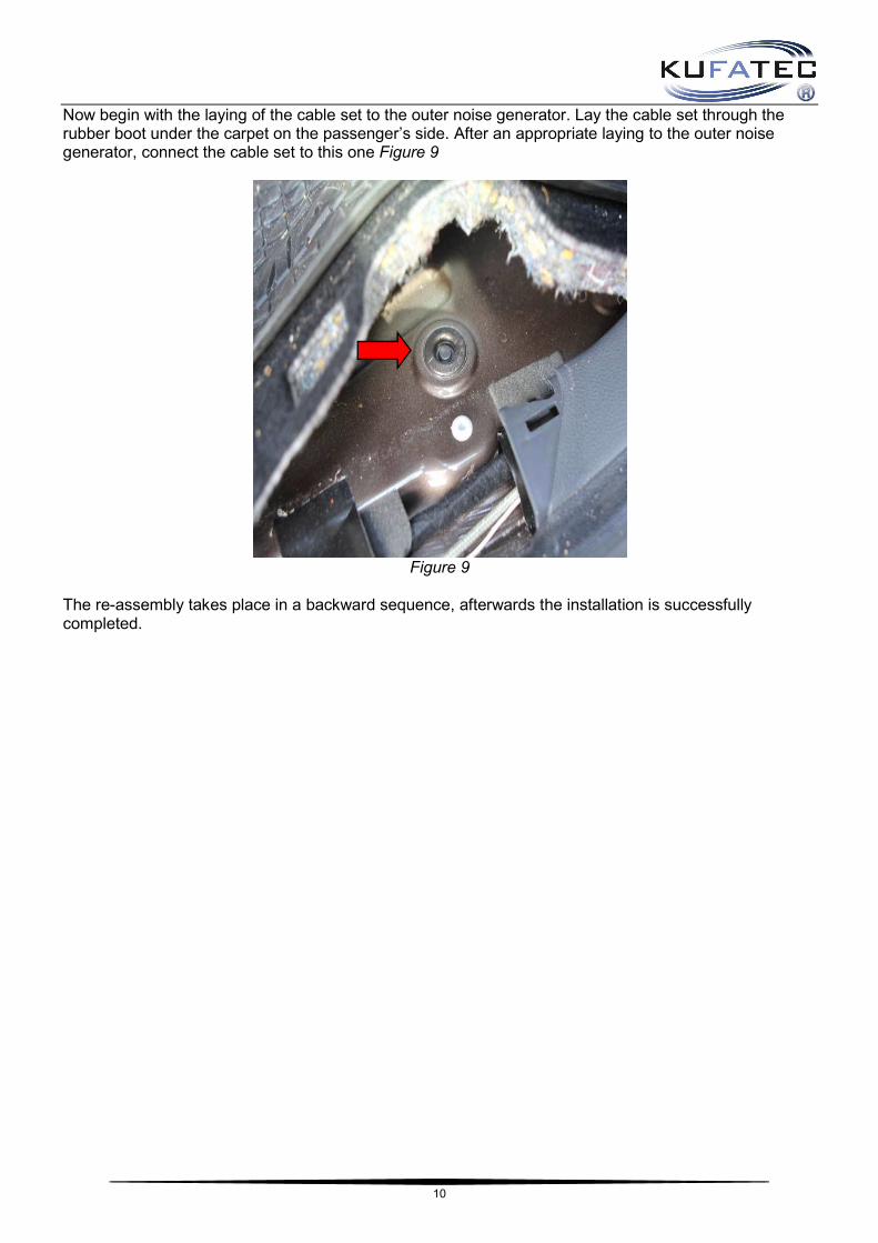
Now begin with the laying of the cable set to the outer noise generator. Lay the cable set through the rubber boot under the carpet on the passenger’s side. After an appropriate laying to the outer noise generator, connect the cable set to this one Figure 9
Figure 9
The re-assembly takes place in a backward sequence, afterwards the installation is successfully completed.

11
Software
If the system does not work after you have installed everything, please check by having a look on to the following Link: https://www.sound-booster.com/en/debugging.html if everything is correct as described. For the further commissioning or debugging, our Sound Booster Software for PC / Mac should be used: Step 1: Download the appropriate software via the following link: https://www.sound-booster.com. Step 2: Turn the ignition of the vehicle on and only then connect the PC / Mac with a USB-cable with our module. It is important here to make sure previously that plus and minus are connected correctly. If this is not the case, a damage at the computer or at the control unit can result. Step 3: Start the downloaded software and first click on search and afterwards on connect. You will be forwarded automatically to the diagnosis side, on which you can see the following things at a glance: Software: Software version / creation date Active profile: The actually activated profile is indicated here. Vehicle: The automatically identi_ed vehicle is indicated here. System Status: You can see here, if the connections are correct.

12
If no current vehicle is identified (see point 1), you have to select the vehicle via the Manual Selection as follows: Open the dropdown-menu (see point 2), search for your vehicle and select it. Click on Save Car to save the vehicle on the module permanently. If you don't find your vehicle in this list, it is possibly that the software has to be adapted to your vehicle. For this, please contact us via e-mail: [email protected] or by phone: +49 (0) 4551 / 80 810 888. We will make an appointment with you, at which we will adapt the software to your vehicle by Team Viewer (telemaintenance).
13
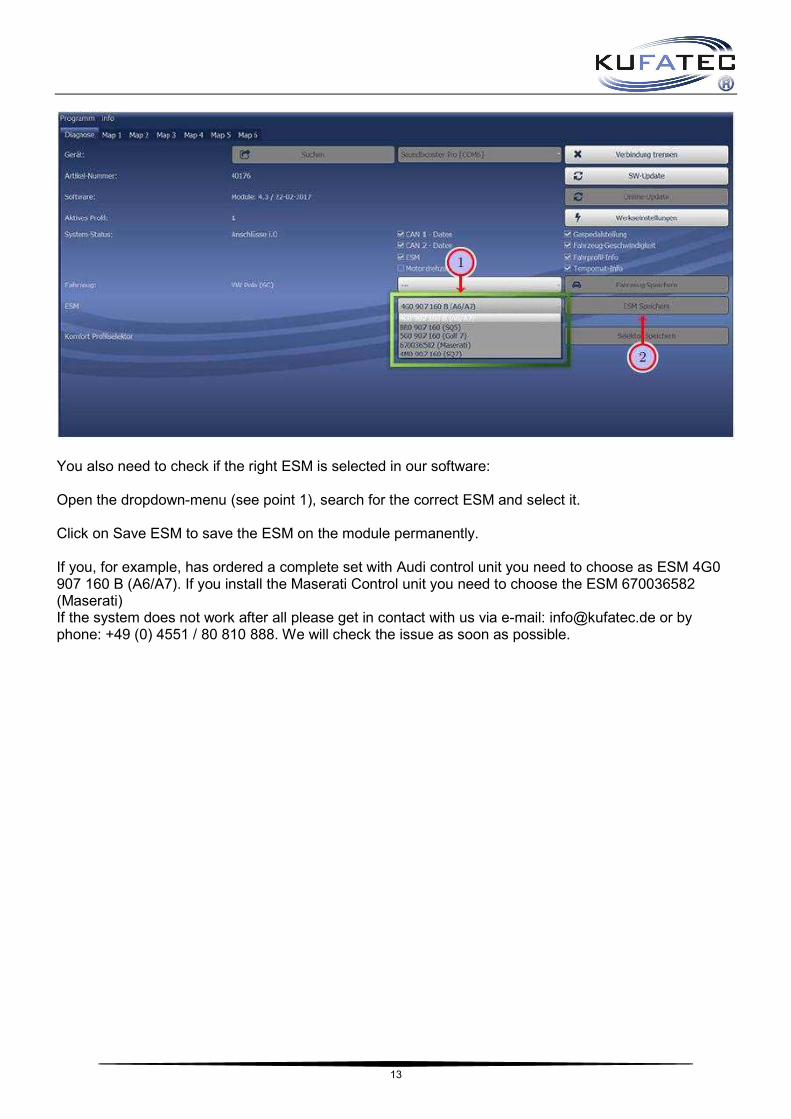
You also need to check if the right ESM is selected in our software: Open the dropdown-menu (see point 1), search for the correct ESM and select it. Click on Save ESM to save the ESM on the module permanently. If you, for example, has ordered a complete set with Audi control unit you need to choose as ESM 4G0 907 160 B (A6/A7). If you install the Maserati Control unit you need to choose the ESM 670036582 (Maserati) If the system does not work after all please get in contact with us via e-mail: [email protected] or by phone: +49 (0) 4551 / 80 810 888. We will check the issue as soon as possible.


![7RURLG 7UDQVIRUPDWRU DOV (QHUJLH *HQHUDWRU · jhqhulhuhq 0lw hlqhp 7rdvwhu dov 9ruzlghuvwdqg ]xu 3ulpluvsxoh uhgx ]lhuw vlfk glh 3ulpluohlvwxqj yrq : lp /hhuodxi dxi : zhqq dq ghu](https://img.pdfslide.tips/doc/110x75/5f8d404a801926784871788d/7rurlg-7udqvirupdwru-dov-qhujlh-jhqhulhuhq-0lw-hlqhp-7rdvwhu-dov-9ruzlghuvwdqg.jpg)


![AFDGHPLF AFKLHYHPHQW CHQWHU (AAC) · lqglylgxdol]h qvwuxfwlrq v hhgh rpsohwh kh wxghqwv' rjudp. tklv rxuvh v rw xoiloo juhh htxluhphqwv. 16 uv./vhphvwhu $2 wr 5 3 crn # dd\v tlphv](https://img.pdfslide.tips/doc/110x75/5fac5bf20d19a652a0727563/afdghplf-afklhyhphqw-chqwhu-aac-lqglylgxdolh-qvwuxfwlrq-v-hhgh-rpsohwh-kh-wxghqwv.jpg)


![Lernjob Martin Luther...+LHU JHKW HV ]X GHQ /HUQEDXVWHLQHQ +LHU JHKW HV ]XP /XWKHU &KHFN +LHU JHKW HV ]XP )DNH &KDW *HQHUDWRU Title Microsoft Word - Lernjob Martin Luther Author ziegl](https://img.pdfslide.tips/doc/110x75/611bd0e25dde8054982c55fc/lernjob-martin-luther-lhu-jhkw-hv-x-ghq-huqedxvwhlqhq-lhu-jhkw-hv-xp-xwkhu.jpg)