Embed Size (px)
Citation preview
© RACOM, Mírová 1283, 592 31 Nové Město na Moravě, Czech Republic
FREE & licensed bands
Interference & obstacle tolerant
Maximum distances & reliability
Narrow channels from 1.75 MHz
ACM, ATPC
Optical + metallic Ethernet
IPTV optimized
PoE or DC (20 - 60 V)
Low power consumption
Climate chamber tested
���������
General
RAy is the high-speed point-to-point microwave link developed and completely manufactured by RACOM, a global leader
in the development and production of high performance, industrial grade wireless equipment. Benefiting from customer
feedback, collected from thousands of units sold, RAy is continually being enhanced and further improved.
The concept of RAy technology, based on excellent sensitivity and interference resistance, allows the user to build links with
high capacity over long distances, whilst maintaining maximum link availability.
Supporting a broad range of options and with an excellent reliability and price/performance ratio, RAy is your perfect product
of choice for every application.
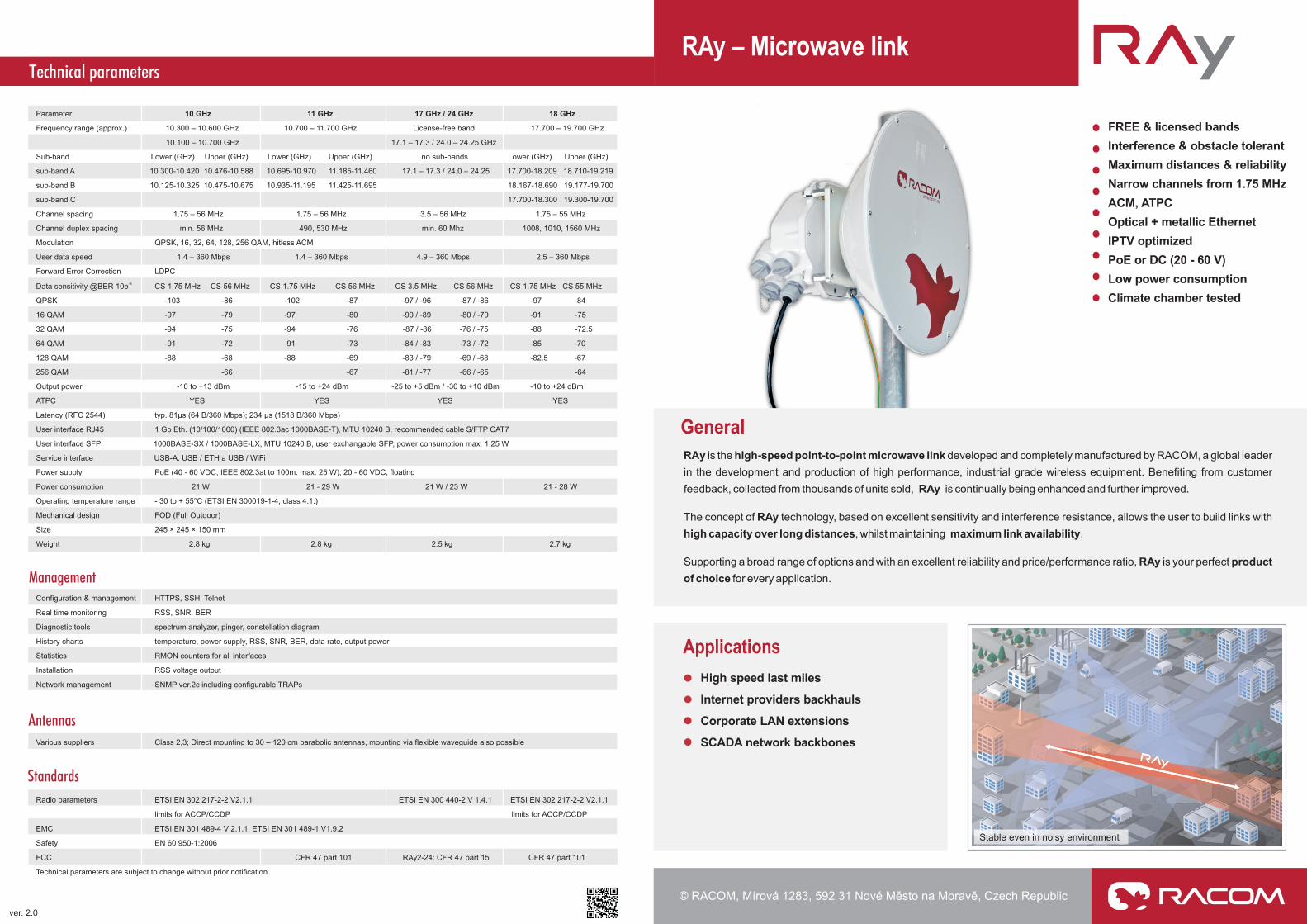
Applications
High speed last miles
Internet providers backhauls
Corporate LAN extensions
SCADA network backbones
����
RAy – Microwave link
ver. 2.0
Stable even in noisy environment
Technical parameters
Management
Standards
Antennas
Parameter 10 GHz 11 GHz 17 GHz / 24 GHz 18 GHz
Frequency range (approx.) 10.300 – 10.600 GHz 10.700 – 11.700 GHz License-free band 17.700 – 19.700 GHz
10.100 – 10.700 GHz 17.1 – 17.3 / 24.0 – 24.25 GHz
Sub-band Lower (GHz) Upper (GHz) Lower (GHz) Upper (GHz) no sub-bands Lower (GHz) Upper (GHz)
sub-band A 10.300-10.420 10.476-10.588 10.695-10.970 11.185-11.460 17.1 – 17.3 / 24.0 – 24.25 17.700-18.209 18.710-19.219
sub-band B 10.125-10.325 10.475-10.675 10.935-11.195 11.425-11.695 18.167-18.690 19.177-19.700
sub-band C 17.700-18.300 19.300-19.700
Channel spacing 1.75 – 56 MHz 1.75 – 56 MHz 3.5 – 56 MHz 1.75 – 55 MHz
Channel duplex spacing min. 56 MHz 490, 530 MHz min. 60 Mhz 1008, 1010, 1560 MHz
Modulation QPSK, 16, 32, 64, 128, 256 QAM, hitless ACM
User data speed 1.4 – 360 Mbps 1.4 – 360 Mbps 4.9 – 360 Mbps 2.5 – 360 Mbps
Forward Error Correction LDPC
-6Data sensitivity @BER 10e CS 1.75 MHz CS 56 MHz CS 1.75 MHz CS 56 MHz CS 3.5 MHz CS 56 MHz CS 1.75 MHz CS 55 MHz
QPSK -103 -86 -102 -87 -97 / -96 -87 / -86 -97 -84
16 QAM -97 -79 -97 -80 -90 / -89 -80 / -79 -91 -75
32 QAM -94 -75 -94 -76 -87 / -86 -76 / -75 -88 -72.5
64 QAM -91 -72 -91 -73 -84 / -83 -73 / -72 -85 -70
128 QAM -88 -68 -88 -69 -83 / -79 -69 / -68 -82.5 -67
256 QAM -66 -67 -81 / -77 -66 / -65 -64
Output power -10 to +13 dBm -15 to +24 dBm -25 to +5 dBm / -30 to +10 dBm -10 to +24 dBm
ATPC YES YES YES YES
Latency (RFC 2544) typ. 81µs (64 B/360 Mbps); 234 µs (1518 B/360 Mbps)
User interface RJ45 1 Gb Eth. (10/100/1000) (IEEE 802.3ac 1000BASE-T), MTU 10240 B, recommended cable S/FTP CAT7
User interface SFP 1000BASE-SX / 1000BASE-LX, MTU 10240 B, user exchangable SFP, power consumption max. 1.25 W
Service interface USB-A: USB / ETH a USB / WiFi
Power supply PoE (40 - 60 VDC, IEEE 802.3at to 100m. max. 25 W), 20 - 60 VDC, floating
Power consumption 21 W 21 - 29 W 21 W / 23 W 21 - 28 W
Operating temperature range - 30 to + 55°C (ETSI EN 300019-1-4, class 4.1.)
Mechanical design FOD (Full Outdoor)
Size 245 × 245 × 150 mm
Weight 2.8 kg 2.8 kg 2.5 kg 2.7 kg
Configuration & management HTTPS, SSH, Telnet
Real time monitoring RSS, SNR, BER
Diagnostic tools spectrum analyzer, pinger, constellation diagram
History charts temperature, power supply, RSS, SNR, BER, data rate, output power
Statistics RMON counters for all interfaces
Installation RSS voltage output
Network management SNMP ver.2c including configurable TRAPs
Various suppliers Class 2,3; Direct mounting to 30 – 120 cm parabolic antennas, mounting via flexible waveguide also possible
Radio parameters ETSI EN 302 217-2-2 V2.1.1 ETSI EN 300 440-2 V 1.4.1 ETSI EN 302 217-2-2 V2.1.1
limits for ACCP/CCDP limits for ACCP/CCDP
EMC ETSI EN 301 489-4 V 2.1.1, ETSI EN 301 489-1 V1.9.2
Safety EN 60 950-1:2006
FCC CFR 47 part 101 RAy2-24: CFR 47 part 15 CFR 47 part 101
Technical parameters are subject to change without prior notification.
Microwave link
Radio parameters
Interfaces
Solution for any application
Security & Standards
Reliability
FREE & licensed bands
Instalation in minutes
Advanced diagnostics
References
Typical Applications
�
�
�
�
�
High radio receiver robustness against unwanted interference
Narrow channels (from 1.75 MHz)
SW selectable modulation: QPSK, 16, 32, 64, 128,
256 QAM
Hitless ACM (Adaptive Coding and Modulation)
ATPC (Automatic Transmit Power Control)
�
�
�
�
�
�
Heavy-duty industrial components
Built-in surge protection
Operating temperature range from -30 to +55 °C certified
Every single unit is thoroughly tested in a climatic
chamber
Quality manufacturing results in exceptional reliability
Rugged input filter with no adjustable components
�
�
�
Ethernet: 1x optical, 1x metallic port configurable as:
2 independent user ports, in-band management
1 user + 1 management port
Power: PoE, DC (20 – 60 V)
USB: Management via USB / ETH or USB / WiFi
�
�
�
Supports both FREE & LICENSED bands
17 & 24 GHz: Identical unit
type offers lower distribution and
storage costs
Widely configurable channel duplex spacing eases
sourcing of available channels
Fulfilling SRD standards.
at both ends of link
�
�
�
High sensitivity together with wide channel width and
modulation enables optimized s for distance and
performance.
MTU 10240 B, MPLS transparent
Packet buffer & QoS optimized for IPTV (multicasts,
unicasts)
link
�
�
�
�
�
Full outdoor unit with aluminium casing
HW reset button for factory and customers settings
Simple signal polarization change by unit's rotation
RSS voltage output for antenna alignment
Direct mounting to parabolic antennas
�
�
�
�
Configuration via HTTPS SSH
ll relevant international standards
Key parameters measured and confirmed by certified
laboratory
and for secured access
Compliance to a
SFP modules, NMS and power supplies have no proprietary
restrictions
�
�
�
�
�
�
Intuitive web interface
Temperature, power supply, RSS, SNR, BER, data rate,
output power status and history avail. as text or charts
SNMP (Including generation of TRAPs)
Built-in spectrum analyzer for free channel search
Automatic detection of unit polarization
Constellation diagram of the received signal
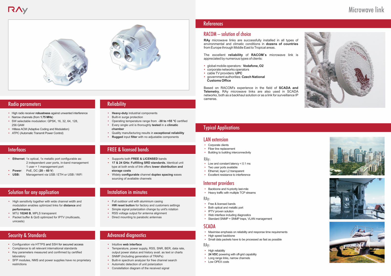
RAy microwave links are successfully installed in all types of environmental and climatic conditions in dozens of countries from Europe through Middle East to Tropical areas.
The excellent reliability of RACOM´s microwave link is appreciated by numerous types of clients:
global mobile operators Vodafonecorporate networks operatorscable TV providers UPCgovernment authorities Czech National
Customs Office
Based on RACOM's experience in the field of SCADA and Telemetry, RAy microwave links are also used in SCADA networks, both as a backhaul solution or as a link for surveillance IP cameras.
� � � �
: , O2
::
RACOM � solution of choice
Corporate clients
Fiber line replacement
Building to building interconnectivity
Low and constant latency < 0.1 ms
Two user ports available
Ethernet, layer L2 transparent
Excellent resistance to interference
�
�
�
�
�
�
�
Backbone and hi-priority last-mile
Heavy traffic with multiple TCP streams
Free & licensed bands
Both optical and metallic port
IPTV proven solution
Web interface including diagnostics
Standard SNMP + SNMP traps VLAN management
�
�
�
�
�
�
� ,
�
�
�
�
�
�
�
Maximise emphasis on reliability and response time requirements
High speed backbone
Small data packets have to be processed as fast as possible
High reliability
24 VDC powering with off-grid capability
Long range links, narrow channels
Low OPEX costs
RAy:
RAy:
RAy:
Internet providers
SCADA
LAN extension