Embed Size (px)
Citation preview
8/12/2019 RC-OSCcal
http://slidepdf.com/reader/full/rc-osccal 1/14
8-bit
Microcontrollers
Application Note
Preliminary
Rev. 2555A-AVR-12/03
AVR053: Calibration of the internal RC oscillator
Features
• Calibration using STK500, AVRISP, or JTAGICE
• Calibration using 3rd
party programmers
• Adjustable RC frequency with +/-1% accuracy
• Tune RC oscillator at any operating voltage and temperature
• Tune RC oscillator to any frequency within spec
• Support for all AVRs with tunable RC oscillator
• Selectable calibration clock frequency
Introduction
The majority of the present AVR microcontrollers offer the possibility to run frominternal RC oscillator. The internal RC oscillator frequency can in most AVRs becalibrated to within +/-1% of the frequency specified in the datasheet for the device.This feature offers great flexibility and significant cost savings compared to usingan external oscillator. The calibration does not take much longer than reading thecalibration value from the signature and writing it to the device memory and doestherefore not add much to the overall programming time.
In production the internal RC is calibrated at 5V or 3.3V. The accuracy of thefactory calibration is within +/-3 or +/-10% depending on the device considered. If adesign’s need for accuracy is beyond what can be offered by the standardcalibration in factory by Atmel, it is possible to perform a secondary calibration ofthe RC oscillator. By doing this it is possible to obtain a frequency accuracy within+/-1 (+/-3% for a few devices). An additional advantage is that the calibration canbe customized to match the operating voltage and expected temperature of theapplication, or even an RC frequency different than the factory default. Theapplication specific calibration can be done while testing the final product or inrelation to programming the AVR flash memory.
This application note describes a method to calibrate the internal RC oscillator andtherefore targets all AVR devices with tunable RC oscillator. Furthermore, an easilyadaptable calibration firmware source code is also offered. This firmware allowsdevice calibration using the AVR tools STK500, AVRISP or JTAGICE, but can alsobe used for 3rd party calibration systems, e.g. based on production programmers.
A Quick Start Guide is present last in this document.
8/12/2019 RC-OSCcal
http://slidepdf.com/reader/full/rc-osccal 2/14
Theory of operation – the internal RC oscillator
The AVR fuse settings control the system clock source being used. To use the
internal RC oscillator, the corresponding fuse setting must be selected. The followingsections provide an overview of the internal RC oscillators available in the AVRmicrocontrollers.
Refer to the datasheet of the relevant device to determine the achievable accuracy forinternal RC oscillator in this device.
Base-frequency Some AVRs have one RC oscillator, while others have up to 4 different RC oscillatorsto choose from. The frequency ranges from 1MHz to 9.6MHz. To make the internalRC oscillator sufficiently accurate an Oscillator Calibration register, OSCCAL, ispresent in the AVR IO file. The OSCCAL register is one byte wide. The purpose ofthis register is to be able to tune the oscillator frequency. This tuning is utilized whencalibrating the RC oscillator.
As mentioned, the devices are calibrated before they leave Atmel. When they arecalibrated the calibration byte, that is the value resulting in +/-1% accuracy for the RCoscillator once programmed into the OSCCAL register, is stored in the Signature Rowof the device. The calibration byte can vary from one device to the other, as the RCoscillator frequency is process dependent. If a device has more than one oscillator acalibration byte for each of the RC oscillators is stored in the Signature Row.
The default RC oscillator calibration byte is in recent devices automatically loadedfrom the Signature Row and copied into the OSCCAL register at start-up. Forexample, the default ATmega8 clock setting is the internal 1MHz RC oscillator; forthis device the calibration byte corresponding to the 1MHz RC oscillator isautomatically loaded at start-up. If the fuses are altered so that the 4MHz oscillator isused instead of the default setting, the calibration byte must be loaded into theOSCCAL register manually. A programming tool can be used to read the 4MHzcalibration byte from the Signature Row and hence store it in a Flash or EEPROMlocation, which is read by the main program and copied into OSCCAL at run-time.
In addition to the oscillator tuning using the OSCCAL register, some devices feature asystem clock prescaler. The prescaler register (CLKPR) can be used to scale thesystem clock with predefined two’s-compliment factors. Also, this prescaler can beenabled through the AVR fuses; programming the CKDIV8 fuse will divide the systemclock by 8. This can be done to ensure that the device is operated below a maximumfrequency specification. The CLKPR can be modified at run-time to change thefrequency of the system clock internally.
The base frequency of an oscillator is defined as the unscaled oscillator frequency.
RC Oscillator overview Different RC oscillators have been utilized in the AVR microcontrollers throughout the
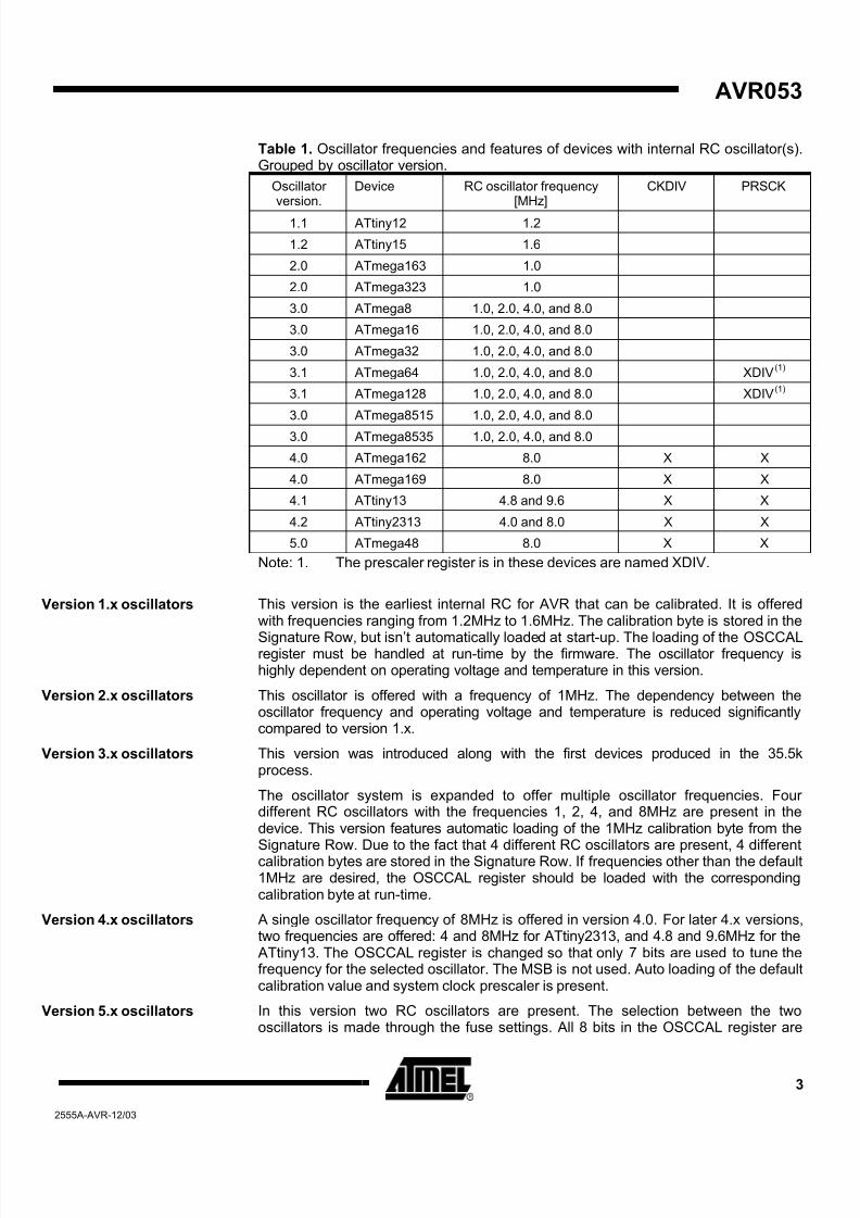
history. An overview of the devices and their RC oscillators is seen in Table 1. Thedevice list is sorted by oscillator type, which is also more or less equivalent to sortingthem by release date. Only devices with tunable oscillators are listed in the table.
2 AVR0532555A-AVR-12/03
8/12/2019 RC-OSCcal
http://slidepdf.com/reader/full/rc-osccal 3/14
AVR053
Table 1. Oscillator frequencies and features of devices with internal RC oscillator(s).Grouped by oscillator version.
Oscillatorversion.
Device RC oscillator frequency[MHz]
CKDIV PRSCK
1.1 ATtiny12 1.2
1.2 ATtiny15 1.6
2.0 ATmega163 1.0
2.0 ATmega323 1.0
3.0 ATmega8 1.0, 2.0, 4.0, and 8.0
3.0 ATmega16 1.0, 2.0, 4.0, and 8.0
3.0 ATmega32 1.0, 2.0, 4.0, and 8.0
3.1 ATmega64 1.0, 2.0, 4.0, and 8.0 XDIV(1)
3.1 ATmega128 1.0, 2.0, 4.0, and 8.0 XDIV(1)
3.0 ATmega8515 1.0, 2.0, 4.0, and 8.0
3.0 ATmega8535 1.0, 2.0, 4.0, and 8.0
4.0 ATmega162 8.0 X X
4.0 ATmega169 8.0 X X
4.1 ATtiny13 4.8 and 9.6 X X
4.2 ATtiny2313 4.0 and 8.0 X X
5.0 ATmega48 8.0 X X
Note: 1. The prescaler register is in these devices are named XDIV.
This version is the earliest internal RC for AVR that can be calibrated. It is offeredwith frequencies ranging from 1.2MHz to 1.6MHz. The calibration byte is stored in the
Signature Row, but isn’t automatically loaded at start-up. The loading of the OSCCALregister must be handled at run-time by the firmware. The oscillator frequency ishighly dependent on operating voltage and temperature in this version.
Version 1.x oscillators
This oscillator is offered with a frequency of 1MHz. The dependency between theoscillator frequency and operating voltage and temperature is reduced significantlycompared to version 1.x.
Version 2.x oscillators
This version was introduced along with the first devices produced in the 35.5kprocess.
Version 3.x oscillators
The oscillator system is expanded to offer multiple oscillator frequencies. Fourdifferent RC oscillators with the frequencies 1, 2, 4, and 8MHz are present in thedevice. This version features automatic loading of the 1MHz calibration byte from theSignature Row. Due to the fact that 4 different RC oscillators are present, 4 differentcalibration bytes are stored in the Signature Row. If frequencies other than the default1MHz are desired, the OSCCAL register should be loaded with the correspondingcalibration byte at run-time.
A single oscillator frequency of 8MHz is offered in version 4.0. For later 4.x versions,two frequencies are offered: 4 and 8MHz for ATtiny2313, and 4.8 and 9.6MHz for the ATtiny13. The OSCCAL register is changed so that only 7 bits are used to tune thefrequency for the selected oscillator. The MSB is not used. Auto loading of the defaultcalibration value and system clock prescaler is present.
Version 4.x oscillators
In this version two RC oscillators are present. The selection between the twooscillators is made through the fuse settings. All 8 bits in the OSCCAL register are
Version 5.x oscillators
3
2555A-AVR-12/03
8/12/2019 RC-OSCcal
http://slidepdf.com/reader/full/rc-osccal 4/14
used to tune the oscillator frequency. Auto loading of the default calibration value andsystem clock prescaler is present.
Oscillatorcharacteristics
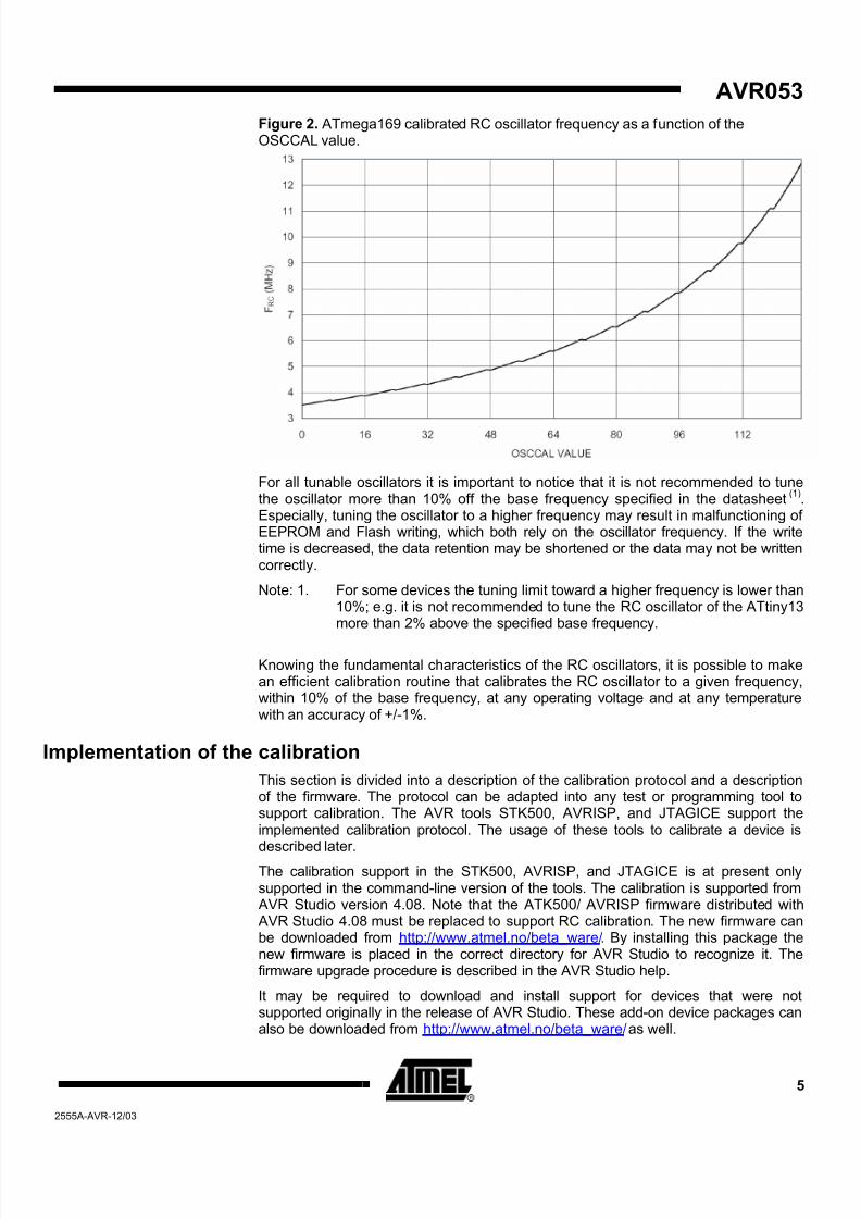
The frequency of the internal RC oscillator is depending on the temperature andoperating voltage. An example of this dependency is seen in Figure 1, which showsthe frequency of the 8MHz RC oscillator of the ATmega169. As seen from the figure,the frequency increases with increasing temperature, and decreases slightly withincreasing operating voltage. These characteristics will vary from device to device.For details on a specific device refer to its datasheet.
Figure 1. Oscillator frequency and influence by temperature and operating voltage. ATmega169 calibrated 8MHz RC oscillator frequency vs. Vcc.
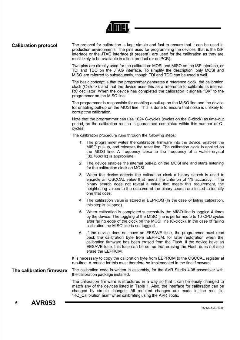
All devices with tunable oscillators have an OSCCAL register for tuning the oscillatorfrequency. An increasing value in OSCCAL will result in a “pseudo-monotone”increase in frequency. The reason for calling it pseudo-monotone is that for someunity increases of the OSCCAL value the frequency will not increase or will decreaseslightly. However, the next unity increase will always increase the frequency again. Inother words, incrementing the OSCCAL register by one may not increase thefrequency, but increasing the OSCCAL value by two will always increase thefrequency. This information is very relevant when searching for the best calibrationvalue to fit a given frequency. An example of the pseudo-monotone relation betweenthe OSCCAL value and the oscillator frequency can be seen in Figure 2, which is the8MHz RC oscillator of ATmega169. Note that since the OSCCAL register only uses 7bits for tuning the oscillator in ATmega169, the maximum frequency is corresponding
to OSCCAL = 128.
4 AVR0532555A-AVR-12/03
8/12/2019 RC-OSCcal
http://slidepdf.com/reader/full/rc-osccal 5/14
AVR053
Figure 2. ATmega169 calibrated RC oscillator frequency as a function of theOSCCAL value.
For all tunable oscillators it is important to notice that it is not recommended to tunethe oscillator more than 10% off the base frequency specified in the datasheet
(1).
Especially, tuning the oscillator to a higher frequency may result in malfunctioning ofEEPROM and Flash writing, which both rely on the oscillator frequency. If the writetime is decreased, the data retention may be shortened or the data may not be writtencorrectly.
Note: 1. For some devices the tuning limit toward a higher frequency is lower than10%; e.g. it is not recommended to tune the RC oscillator of the ATtiny13more than 2% above the specified base frequency.
Knowing the fundamental characteristics of the RC oscillators, it is possible to makean efficient calibration routine that calibrates the RC oscillator to a given frequency,within 10% of the base frequency, at any operating voltage and at any temperaturewith an accuracy of +/-1%.
Implementation of the calibration
This section is divided into a description of the calibration protocol and a descriptionof the firmware. The protocol can be adapted into any test or programming tool tosupport calibration. The AVR tools STK500, AVRISP, and JTAGICE support theimplemented calibration protocol. The usage of these tools to calibrate a device isdescribed later.
The calibration support in the STK500, AVRISP, and JTAGICE is at present onlysupported in the command-line version of the tools. The calibration is supported from AVR Studio version 4.08. Note that the ATK500/ AVRISP firmware distributed with AVR Studio 4.08 must be replaced to support RC calibration. The new firmware canbe downloaded from http://www.atmel.no/beta_ware/. By installing this package thenew firmware is placed in the correct directory for AVR Studio to recognize it. Thefirmware upgrade procedure is described in the AVR Studio help.
It may be required to download and install support for devices that were notsupported originally in the release of AVR Studio. These add-on device packages canalso be downloaded from http://www.atmel.no/beta_ware/ as well.
5
2555A-AVR-12/03
8/12/2019 RC-OSCcal
http://slidepdf.com/reader/full/rc-osccal 6/14
6 AVR0532555A-AVR-12/03
Calibration protocol The protocol for calibration is kept simple and fast to ensure that it can be used inproduction environments. The pins used for programming the devices, that is the ISPinterface or the JTAG interface (if present), are used for the calibration as they are
most likely to be available in a final product (or on PCB).Two pins are directly used for the calibration: MOSI and MISO on the ISP interface, orTDI and TDO on the JTAG interface. To simplify the description, only MOSI andMISO are referred to subsequently, though TDI and TDO can be used a well.
The basic concept is that the programmer generates a reference clock, the calibrationclock (C-clock), and that the device uses this as a reference to calibrate its internalRC oscillator. When the device has completed the calibration it signals “OK” to theprogrammer on the MISO line.
The programmer is responsible for enabling a pull-up on the MISO line and the devicefor enabling pull-up on the MOSI line. This is done to ensure that noise is unlikely tocorrupt the calibration.
Note that the programmer can use 1024 C-cycles (cycles on the C-clock) as time-outperiod, as the calibration routine is guaranteed completed within this number of C-cycles.
The calibration procedure runs through the following steps:
1. The programmer writes the calibration firmware into the device, enables theMISO pull-up, and releases the reset line. The calibration clock is applied onthe MOSI line. A frequency close to the frequency of a watch crystal(32.768kHz) is appropriate.
2. The device enables the internal pull-up on the MOSI line and starts listeningfor the calibration clock on MOSI.
3. When the device detects the calibration clock a binary search is used to
encircle an OSCCAL value that meets the criterion of 1% accuracy. If thebinary search does not reveal a value that meets this requirement, theneighboring values to the outcome of the binary search are tested to identifyone that does.
4. The calibration value is stored in EEPROM (In the case of failing calibration,this step is skipped).
5. When calibration is completed successfully the MISO line is toggled 4 timesby the device. The toggling of the MISO line is performed 5 to 10 CPU cyclesafter falling edge of the clock on the MOSI line (C-clock). In the case of failingcalibration the MISO line is not toggled.
6. If the device does not have an EESAVE fuse, the programmer must read
back the calibration byte from EEPROM, for later restoration when thecalibration firmware has been erased from the Flash. If the device have anEESAVE fuse, this fuse can be set so that erasing the Flash does not alsoerase the EEPROM.
It is necessary to copy the calibration byte from EEPROM to the OSCCAL register atrun-time. A routine for this must therefore be implemented in the final firmware.
The calibration firmware The calibration code is written in assembly, for the AVR Studio 4.08 assembler withthe calibration package installed.
The calibration firmware is structured in a way so that it can be easily changed tomatch any of the devices listed in Table 1. Also, the interface for calibration can bechanged by simple changes. All required changes are made in the root file“RC_Calibration.asm” when calibrating using the AVR Tools.
8/12/2019 RC-OSCcal
http://slidepdf.com/reader/full/rc-osccal 7/14
AVR053
The root file refers to (includes) the following files:
1. A device specific file (select the one matching the target device), e.g.“m8.asm” for ATmega8. The device-specific file further includes the following:
a. The register and bit definition distributed with AVR Studio.
b. A memory map file that defines where the code is located and whichEEPROM location to store the calibration byte in.
c. An OSCCAL access macro file that controls how the OSCCALregister is accessed. The way of accessing the OSCCAL registerdepends on where in the IO file the OSCCAL register is located.
d. An oscillator version file. This file defines the initial step-size used inthe binary search to account for the fact that some OSCCAL registersare 7 and some are 8 bits wide.
e. A Return Stack initialization macro file. Some devices have hardwarestack, while others have a stack in SRAM that needs initialization.
f. A port access macro file, which defines how to access the registers
related to the pins used in the calibration. This is needed since someregisters are in the high part of the IO file and others are in the lowpart of the IO file.
g. Redefinitions of bit and register names may also be present in thedevice file.
2. A calibration interface specific file. This file assigns the ISP or JTAG port andpins with names (labels) used in the main code. The calibration clockfrequency is specified in this file.
3. The file defining the macros used - “macros.inc”
4. The common calibration code “main.asm”
The structure of the calibration code is designed to make changes easy in order tomatch a desired target device and interface. Furthermore, the extensive use ofmacros is to ensure that the code gets the smallest possible footprint. Finally, the wayof defining devices and calibration interfaces is to ensure that support for new devicesor interfaces can be implemented with a minimum of effort.
The search is based on a binary search method, a divide-and-conquer method:Binary search method
1. The OSCCAL register is loaded with the initial value, which is half themaximum value of OSCCAL. The initial value of OSCCAL is defined as theinitial Step-Size.
2. The frequency of the system clock is then compared to an external reference,the calibration clock.
a. If the frequency is within 1% accuracy limit, goto 5.
b. If the system clock is found to be too fast the OSCCAL value isreduced, and if the clock is too slow OSCCAL is increased. Goto 3.
3. Step-Size is assigned the value of half the previous Step-Size.
a. If the Step-Size is zero, the binary search has not been successful,goto 4.
b. If Step-Size is different from zero, the Step-Size is added to orsubtracted from the current value in the OSCCAL register to increaseor decrease the oscillator frequency. Repeat step 2.
7
2555A-AVR-12/03
8/12/2019 RC-OSCcal
http://slidepdf.com/reader/full/rc-osccal 8/14
4. Test the 4 nearest neighbor-values of OSCCAL. This is done to compensatefor the lack of a strictly monotonous relationship between OSCCAL andoscillator frequency.
a. If a tested OSCCAL value is within the accuracy limits, goto 5
b. If none of the tested OSCCAL values are within the limits (notexpected), signal on MISO that the calibration has failed by drivingthe line low.
5. Store the calibration value in the EEPROM
6. Signal that calibration has been completed successfully by toggling the MISOline 4 times, synchronously to the calibration clock toggling.
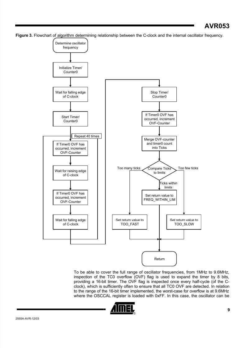
The comparison between the Calibration clock (C-clock) and the internal RC oscillatoris performed using the 8-bit Timer/Counter0 (TC0). The 8-bit timer is used since it ispresent in all devices that have tunable RC oscillator. The idea is to time the durationof 40 C-clock cycles and compare the number of timer ticks to predefined limits. TheC-frequency in the present implementation is 32.623kHz. The method for determiningthe oscillator frequency is described in the flowchart in Figure 3.
Method for determining theoscillator frequency
8 AVR0532555A-AVR-12/03
8/12/2019 RC-OSCcal
http://slidepdf.com/reader/full/rc-osccal 9/14
AVR053
Figure 3. Flowchart of algorithm determining relationship between the C-clock and the internal oscillator frequency.
Wait for falling edge
of C-clock
Start Timer/
Counter0
Initialize Timer/
Counter0
If Timer0 OVF has
occurred, increment
OVF-Counter
Wait for raising edge
of C-clock
If Timer0 OVF has
occurred, increment
OVF-Counter
Wait for falling edge
of C-clock
If Timer0 OVF has
occurred, increment
OVF-Counter
Compare Ticks
to limits
Merge OVF-counter
and timer0 count
into Ticks
Set return value to
FREQ_WITHIN_LIM
Set return value to
TOO_SLOW
Set return value to
TOO_FAST
Return
Determine oscillator
frequency
Too few ticksToo many ticks
Ticks withinlimits
Stop Timer/
Counter0
Repeat 40 times
To be able to cover the full range of oscillator frequencies, from 1MHz to 9.6MHz,inspection of the TC0 overflow (OVF) flag is used to expand the timer by 8 bits,providing a 16-bit timer. The OVF flag is inspected once every half-cycle (of the C-clock), which is sufficiently often to ensure that all TC0 OVF are detected. In relationto the range of the 16-bit timer implemented, the worst-case for overflow is at 9.6MHzwhere the OSCCAL register is loaded with 0xFF. In this case, the oscillator can be
9
2555A-AVR-12/03
8/12/2019 RC-OSCcal
http://slidepdf.com/reader/full/rc-osccal 10/14
100% above the specified frequency. The timer will in this case count to 23,541,which is within the range of the 16-bit timer.
Going in the other direction, the lowest oscillator frequency must also be considered.The lowest obtainable frequency is when writing 0x00 to OSCCAL. In that case thefrequency may be 50% lower than the specified one. Since the TC0 OVF flag isinspected every half-cycle, there is potentially no more than just above 7 CPU-cyclesto handle the OVF flag and detect the next C-clock edge - at a specified frequency of1MHz. This timing constraint can be met when the OVF flag is not set, but when theflag is set 8 cycles are required. This will cause a small error in the detection of thetiming, but will not affect the overall outcome: the oscillator will correctly bedetermined as too slow.
These extremes are however very unlikely to be encountered due to the binarysearch method used. However, they may be relevant to consider if the calibrationmethod is modified.
Since it is not possible to use interrupt driven detection for the C-clock edges, apolling method is implemented. The consequence of this implementation is that theedge detection can be delayed by up to 2 CPU cycles. Potentially this can make thecalibration fail to reach the desired accuracy of 1%. To compensate for this potentialtiming error, the limits are tightened by 2 timer-ticks (2 CPU-cycles).
Correcting timinginaccuracies
All calculations of limits and constants are performed by the preprocessor, which uses32 bit accuracy. All values that cannot be represented (floats) are rounded towards atighter accuracy and will therefore not endanger the goal of +/-1% accuracy for theoscillator.
Using STK500 or JTAGICE for calibration
The source code of the calibration firmware and the batch file provided is made as an
example of how to use the STK500, AVRISP, or the JTAGICE to perform calibration.The firmware needs few or no modifications to be used in other calibration systems.
Assembling thecalibration firmware
The root file for the calibration firmware is the RC_Calibration.asm file. This file isadded to an assembly project in AVR Studio 4.07 (or later). In this file it is possible toinclude the target device and specify the desired calibration interface: STK500, AVRISP, or JTAG. Further, it is possible to specify the desired calibration accuracy,and not least the desired frequency of the target device.
Once these choices have been made, build the project to produce the binary file“RC_Calibration.hex”. This file is used to calibrate the device.
Note that it is important to ensure that the fuses are set up correctly before calibratingthe device: it is not possible to calibrate a device to 8.0MHz if the 1MHz RC oscillator
is selected by the fuse settings.Using the command linetools
As mentioned earlier, the calibration support in the STK500, AVRISP, and JTAGICEis at present only supported in the command-line version of the tools (AVR Studio4.08). Note that an AVR Studio update is required to support the RC calibration inSTK500 and AVRISP firmware. The software package that provides this support canbe found at http://www.atmel.no/beta_ware/. Please install this package for calibrationsupport.
The package includes a new firmware for the AVR tools, which is required to enablecalibration. The firmware upgrade procedure is described in the AVR Studio help.
10 AVR0532555A-AVR-12/03
Two batch files are provided along with the source code. These batch files show howthe command line tools can be used to program the calibration code into the targetdevice, perform the calibration and hence reprogram the device with the final
8/12/2019 RC-OSCcal
http://slidepdf.com/reader/full/rc-osccal 11/14
AVR053
firmware. The two batch files are performing calibration of the ATmega16 through theSTK500 and the JTAGICE, respectively. Please study these batch files and theSTK500.exe integrated help (STK500.exe -?) to understand the use of theSTK500/JTAGICE command line tools.
Adding support for newdevices
To add support for a new device all that is needed is to copy the device file for a
similar device (pin compatible if possible) and adapt it to the new device’scharacteristics. The checklist below can be used when adapting a file to a newdevice. The checklist uses the ATmega8535 as example.
Copy the device file for a pin and feature compatible device.
o The ATmega8535 is pin compatible with ATmega16, though the ATmega8535 has no JTAG interface. The file “m16.asm” is thereforecopied and named “m8535.asm”
Change the register and bit definition file included to match the new device
o For the ATmega8535 the register and bit definition file is “m8535.inc”
Change the pin-out description file to match the pin-out of the device.
o Since the ATmega8535 does not have JTAG interface as the ATmega16, the pin-out file is changed to the“s8535_family_pinout.inc” file.
Change the oscillator version file to match the oscillator of the new device.
Add the new file to the device list in the RC_Calibration file.
Verify that it assembles correctly. If it does not, this is most likely due tochanged register or bit names of ports, pins, or timers. Use the file for ATtiny13 (t13.asm) as reference to reassign names.
Performance of the Calibration firmware
The code has been written with focus on efficiency: The entire calibration should beperformed fairly quickly. The performance therefore depends on the size of thecalibration firmware and the time it takes to complete the calibration.
The calibration firmware is 183 to 240 bytes, depending on the target device and theinterface used for calibration. The required time to program the firmware is thereforeshort.
The calibration routine is completed in less than 1024 calibration cycles. The shortestduration is however dependent on how fast the binary search algorithm can find asuitable OSCCAL value, and the write time of the EEPROM. In the presentimplementation, using STK500.exe or JTAGICE.exe, the calibration itself iscompleted in less than 32ms.
Quick Start Guide to Calibration of the internal RCTo get started using the calibration feature in one of the device already supported onecan follow steps below.
1. Download and unzip the source code for AVR053 (any location can be used,here called \AVR053\).
2. Download and install AVR Studio 4.08 and the Calibration add-on(http://www.atmel.no/beta_ware/as4/rc_calib/AvrOsccal.msi)
3. Open AVR Studio, make a new project, and add the root source code file,RC_Calibration.asm, to the project.
11
2555A-AVR-12/03
8/12/2019 RC-OSCcal
http://slidepdf.com/reader/full/rc-osccal 12/14
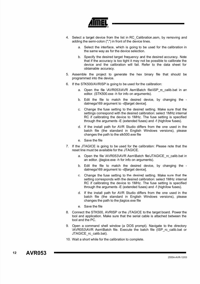
4. Select a target device from the list in RC_Calibration.asm, by removing andadding the semi-colon (";") in front of the device lines.
a. Select the interface, which is going to be used for the calibration inthe same way as for the device selection.
b. Specify the desired target frequency and the desired accuracy. Notethat if the accuracy is too tight it may not be possible to calibrate thedevice and the calibration will fail. Refer to the data sheet forobtainable accuracy.
5. Assemble the project to generate the hex binary file that should beprogrammed into the device.
6. If the STK500/AVRISP is going to be used for the calibration:
a. Open the file \AVR053\AVR Asm\Batch file\ISP_rc_calib.bat in aneditor. (STK500.exe -h for info on arguments).
b. Edit the file to match the desired device, by changing the -datmega169 argument to -d[target device].
c. Change the fuse setting to the desired setting. Make sure that thesettings correspond with the desired calibration: select 1MHz internalRC if calibrating the device to 1MHz. The fuse setting is specifiedthrough the arguments -E (extended fuses) and -f (high/low fuses).
d. If the install path for AVR Studio differs from the one used in thebatch file (the standard in English Windows versions), pleasechanges the path to the stk500.exe file
e. Save the file
7. If the JTAGICE is going to be used for the calibration: Please note that the
reset line must be available for the JTAGICE.
a. Open the file \AVR053\AVR Asm\Batch file\JTAGICE_rc_calib.bat inan editor. (jtagice.exe -h for info on arguments).
b. Edit the file to match the desired device, by changing the -datmega169 argument to -d[target device].
c. Change the fuse setting to the desired setting. Make sure that thesetting corresponds with the desired calibration: select 1MHz internalRC if calibrating the device to 1MHz. The fuse setting is specifiedthrough the arguments -E (extended fuses) and -f (high/low fuses).
d. If the install path for AVR Studio differs from the one used in thebatch file (the standard in English Windows versions), pleasechanges the path to the jtagice.exe file
e. Save the file
8. Connect the STK500, AVRISP or the JTAGICE to the target board. Power thetool and application. Make sure that the serial cable is attached between thetool and the PC.
9. Open a command shell window (a DOS prompt). Navigate to the directory\AVR053\AVR Asm\Batch file. Execute the batch file (ISP_rc_calib.bat orJTAGICE_rc_calib.bat).
10. Wait a short while for the calibration to complete.
12 AVR0532555A-AVR-12/03
8/12/2019 RC-OSCcal
http://slidepdf.com/reader/full/rc-osccal 13/14
AVR053
The batch file can also be modified to program a custom firmware rather than thetest.hex firmware after the calibration. Be aware that the new calibration value shouldbe loaded into the OSCCAL register at runtime by the firmware to be apply.
13
2555A-AVR-12/03
8/12/2019 RC-OSCcal
http://slidepdf.com/reader/full/rc-osccal 14/14
Atmel Corporation
2325 Orchard ParkwaySan Jose, CA 95131, USATel: 1(408) 441-0311Fax: 1(408) 487-2600
Regional Headquarters
Europe Atmel SarlRoute des Arsenaux 41Case Postale 80CH-1705 FribourgSwitzerlandTel: (41) 26-426-5555Fax: (41) 26-426-5500
AsiaRoom 1219Chinachem Golden Plaza77 Mody Road TsimshatsuiEast KowloonHong KongTel: (852) 2721-9778Fax: (852) 2722-1369
Japan9F, Tonetsu Shinkawa Bldg.1-24-8 ShinkawaChuo-ku, Tokyo 104-0033JapanTel: (81) 3-3523-3551Fax: (81) 3-3523-7581
Atmel Operations
Memory2325 Orchard ParkwaySan Jose, CA 95131, USATel: 1(408) 441-0311Fax: 1(408) 436-4314
Microcontrollers2325 Orchard ParkwaySan Jose, CA 95131, USATel: 1(408) 441-0311Fax: 1(408) 436-4314
La ChantrerieBP 7060244306 Nantes Cedex 3, FranceTel: (33) 2-40-18-18-18Fax: (33) 2-40-18-19-60
ASIC/ASSP/Smart CardsZone Industrielle13106 Rousset Cedex, FranceTel: (33) 4-42-53-60-00Fax: (33) 4-42-53-60-01
1150 East Cheyenne Mtn. Blvd.Colorado Springs, CO 80906, USA
Tel: 1(719) 576-3300Fax: 1(719) 540-1759
Scottish Enterprise Technology ParkMaxwell BuildingEast Kilbride G75 0QR, ScotlandTel: (44) 1355-803-000Fax: (44) 1355-242-743
RF/AutomotiveTheresienstrasse 2Postfach 353574025 Heilbronn, GermanyTel: (49) 71-31-67-0Fax: (49) 71-31-67-2340
1150 East Cheyenne Mtn. Blvd.Colorado Springs, CO 80906, USATel: 1(719) 576-3300Fax: 1(719) 540-1759
Biometrics/Imaging/Hi-Rel MPU/
High Speed Converters/RF Datacom Avenue de RochepleineBP 12338521 Saint-Egreve Cedex, FranceTel: (33) 4-76-58-30-00Fax: (33) 4-76-58-34-80
Literature Requestswww.atmel.com/literature
Disclaimer: Atmel Corporation makes no warranty for the use of its products, other than those expressly contained in the Company’s standardwarranty which is detailed in Atmel’s Terms and Conditions located on the Company’s web site. The Company assumes no responsibility for
any errors which may appear in this document, reserves the right to change devices or specifications detailed herein at any time without notice,and does not make any commitment to update the information contained herein. No licenses to patents or other intellectual property of Atmelare granted by the Company in connection with the sale of Atmel products, expressly or by implication. Atmel’s products are not authorized foruse as critical components in life support devices or systems.
© Atmel Corporation 2003. All rights reserved. Atmel® and combinations thereof, AVR® , and AVR Studio® are the registeredtrademarks of Atmel Corporation or its subsidiaries. Microsoft® , Windows® , Windows NT® , and Windows XP® are the registered trademarksof Microsoft Corporation. Other terms and product names may be the trademarks of others
2555A-AVR-12/03