Embed Size (px)
Citation preview

© 2014 ISIJ 342
ISIJ International, Vol. 54 (2014), No. 2, pp. 342–350
Recent Developments of a Numerical Model for Continuous Casting of Steel: Model Theory, Setup and Comparison to Physical Modelling with Liquid Metal
Pavel Ernesto RAMIREZ LOPEZ,1)* Pooria Nazem JALALI,1) Johan BJÖRKVALL,1) Ulf SJÖSTRÖM1) andChrister NILSSON2)
1) Swerea MEFOS AB, Aronstorpsvägen 1, SE 97 437 Luleå, Sweden.2) Senior Specialist R&D, Metallurgical Development, SSAB EMEA, 971 88 Luleå, Sweden.
(Received on September 24, 2013; accepted on November 5, 2013)
Recent developments of an advanced numerical model for Continuous Casting of steel unveiled at theprevious 2010 CSSCR Conference in Sapporo, Japan are presented. These include coupling of the existingmultiphase, heat transfer and solidification model to argon injection for tracking bubble trajectories in theSEN, metal bulk and across the slag bed after passing through the metal surface. Hence, description of amethod for adding gas injection in combination with a multiphase model for tracking metal/slag interfaces(Discrete Phase Model + Volume Of Fluid, DPM+VOF) is given.
Validation is supported by tests on a revamped Continuous Casting Simulator (CCS-1) based on a lowmelting point alloy, which can realistically replicate the flow conditions in the caster. Metal-slag-argon flowpredictions were compared to observations in the physical model showing good agreement on featuressuch as discharging jets, rolls, standing waves and argon distribution measured through a variety of tech-niques such as ultrasound, electromagnetic probes and video sequences.
Ultimately, the model makes possible the prediction of stable or unstable flows within the mould as afunction of different argon flow-rates and bubble sizes. Application to industrial practice is an ongoing taskand preliminary results are illustrated. The robustness of the model combined with direct observations inCCS-1 make possible the description of phenomena difficult to observe in the caster (e.g. argon injectionand metal flow), but critical for the stability of the process and the quality of cast products.
KEY WORDS: argon injection; numerical modelling; plant trials; liquid metal experiments; multiphase/multi-scale models; slag infiltration.
1. Introduction
An appropriate control of the metal flow in the SubmergedEntry Nozzle (SEN) and mould during Continuous Casting(CC) is critical to ensure the quality of products and safeoperation of the caster. However, controlling the liquid steelinside the mould is not a trivial task and unstable flow prob-lems plague the operation of modern casters.1–4) Unsteadyflows often lead to poor level control and uneven solidifica-tion within the mould; which have been linked to the for-mation of defects such as deep oscillation marks, cracks,depressions, etc.5–7) These defects are strongly linked to themechanisms of initial shell solidification and growth in themould. However, solidification itself is a complex combina-tion of physical phenomena which include heat transfer,phase transformations and solid mechanics interactingsimultaneously with the metal flow to form the solid shellwithin a time lapse of few seconds.
Numerical modelling is a feasible alternative to describe
these mechanisms. However, the application of numericalmodelling for solving multi-physics problems has onlybecome widespread in the last decade with the advent offaster computers and advanced numerical models. Forinstance, application of multiphase-flow models coupled toheat transfer and solidification has been a relevant topic forseveral groups in the past years.8–11) Despite the tremendousefforts dedicated to developing these casting models; manyof the physical phenomena involved are yet difficult toexplain or understand. One of the most important phenom-ena yet to be fully described is the effect of argon injectionon the metal flow and its repercussions on heat transfer andsolidification. Nevertheless, argon injection is often treatedseparately because of its complexity and computationaleffort needed to solve it. In prior investigations, the incor-poration of argon into the calculations is limited to its effectson the dynamics of the metal flow.12–15) However, the inher-ently turbulent and highly transient flow combined withargon may produce excessive fluctuations in the metal level,which are the source of problems like those described ear-lier. This behaviour has been rarely associated with thedynamics of the meniscus and its effects on solidification.16)
* Corresponding author: E-mail: [email protected]: http://dx.doi.org/10.2355/isijinternational.54.342

ISIJ International, Vol. 54 (2014), No. 2
343 © 2014 ISIJ
Moreover, little is known about the relationship betweenmetal level fluctuations and the dynamic behaviour of argonbubbles as they travel through the slag bed, which is impor-tant for heat transfer and insulation.
The authors have recently presented a multi-phase/multi-scale model capable of addressing some of these issues bycoupling the metal flow dynamics with heat transfer andsolidification within the mould.17,18) The model also takesinto account many important parameters such as oscillationand slag infiltration.8) However, the effect of argon injectionwas still missing. Hence, the next logical step of develop-ment is to add argon injection to the existing model andvalidate its predictions with physical models and directobservations in the casters. A 1:1 scale physical model hasbeen developed at Swerea MEFOS with the purpose ofstudying this type of flow problems and to surpass short-comings with water modelling (e.g. similarity criteria can-not be entirely fulfilled compared to the industrial systemdue to large differences on scale, density, viscosity, surfacetension forces, etc.). This liquid metal model known asContinuous Casting Simulator 1 (CCS-1) uses a low-meltingpoint alloy (with physical properties very close to steel) tostudy the steel flow through the Submerged Entry Nozzle(SEN) and mould. Liquid metal models are scarce, being theLIMMCAST model at Dresden-Rossendorf the only otherfacility of this kind in Europe; however, it is incapable ofusing real-size ceramic stopper and nozzles due to its smallerscale compared to CCS-1.19) Even though liquid metal mod-elling is not new itself, new measuring tools to track veloc-ities in the metal have just recently reached maturity.19–24)
For instance, measurements of velocity with ultrasound andelectromagnetic probes have proven extremely useful incharacterizing the metal flow in the mould for a Europeanproject carried out by the authors.25) In fact, the use of CCS-1 allows a closer representation of the conditions in the realcaster; while at the same time provides a more permissibleenvironment for developing instrumentation (e.g. loweroperation temperatures=safer tests). The present text focuseson the description of new modelling techniques for addingargon injection to the “base numerical model” developed byMEFOS and the validation of these predictions throughmeasurements the Casting Simulator CCS-1 and plantobservations.
2. Base Numerical Model
The model developed by MEFOS couples a multiphasesteel-slag approach with the heat transfer, mould oscillationand resultant solidification within the CC mould. The modeluses the commercial code ANSYS-FLUENT 12.0 to solvethe Navier-Stokes equations coupled with the Volume ofFluid (VOF) method for calculation of the phase fractionsand the Continuum Surface Force (CSF) method for track-ing of the slag/metal/air interfaces and surface tensioneffects in the meniscus.26,27) The κ-ε RNG turbulence modelis used to capture the flow turbulence, while heat transfer issolved through the Fourier equation. Heat extracted throughthe mould by the water jacket is calculated through aconstant convection heat transfer coefficient based on theNusselt number using typical water flow rates measured on-plant and a free stream temperature of 20°C.28) The heat
flow through the slag bed is solved explicitly by the additionof casting powder on top of the metal bulk plus the calcu-lation of the standard energy equation for a multiphase sys-tem on the VOF model.29) The boundary condition for themould top depends on the casting practice, being the ambi-ent temperature if the slag does not fill entirely the mouldand air is present. Otherwise, the powder temperature mea-sured with a thermal-camera is used if the mould is filled tillthe top. The thicknesses of the powdered, sinter and liquidslag layers are determined by the thermal conductivity of theslag as a function of temperature. The interfacial resistancebetween the solid slag and the mould or contact resistanceas described by Spitzer et al.30) has been computed as afunction of the powder’s basicity.31) Although full details ofthe solution method have been published elsewhere;17,18,31)
Fig. 1(a) shows the boundary conditions used for the basemodel and additional conditions for argon injection. Meshsize ranges from 25–30 microns at the slag film, 0.5–1 mm
Fig. 1. Numerical model for Continuous Casting, a) Boundary con-ditions used for base model and argon injection and b)Schematics of multiple phases present during casting (left)and typical metal flow predictions (right).

© 2014 ISIJ 344
ISIJ International, Vol. 54 (2014), No. 2
at the slag-metal interface and around the SEN ports to4 mm in the bulk flow. Typical time step is 0.005 for caseswith c.a. 300 000–350 000 cells. Predictions include the cal-culation of the metal flow pattern inside the mould, the met-al level height (i.e. metal-slag interface) as well as thebehaviour of slag in the bed. The withdrawal of the solidi-fied shell drags liquid slag into the gap to produce infiltra-tion (i.e. lubrication). This process is affected by castingconditions such as mould oscillation, powder composition,level control, rim formation, etc. Typical metal flow patternpredictions are shown in Fig. 1(b). These reveal typical flowstructures such as jet and rolls but also the formation of astanding wave towards the narrow face resulting from theparticular SEN design.
3. Modelling Argon Injection through the DPM+VOFApproach
Argon injection is frequently used during continuous cast-ing in order to improve the removal of inclusions, which aretransported by the argon-bubbles stream to the slag bed; tobe later assimilated in the liquid slag pool and released tothe atmosphere. A good deal of research has been done inthis subject in the past 20 years, with 2 numerical methodsas possible solutions to address the argon injection phenom-ena; namely Euler-Euler approach and Euler-Lagrangianapproach.32–37) The Euler-Euler approach implies the track-ing of two different sets of equations, one for the continuumphase (steel in this case) and one for the dispersed phase(argon). The phases are solved as non-interpenetrating,immiscible media with their own material properties (den-sity, viscosity, thermal conductivity, etc.); thus, a completeset of flow equations (Navier-Stokes) is solved for eachphase.34) Although very accurate, this approach is alreadycomputationally expensive for 2 phases, and becomesextremely time consuming for a multiphase system such asthe continuous casting process (slag+metal+argon).
In the Euler-Lagrangian approach, the fluid phase is treat-ed as a continuum by solving the Navier-Stokes equations,while the dispersed phase is solved by tracking the bubblesthrough the calculated flow field in a “superimposed” way.The dispersed phase can exchange momentum, mass, andenergy with the fluid phase; where the trajectories of thebubbles or particles that conform it are computed individu-ally at specific intervals (i.e. particle or flow time step) dur-ing the continuum phase calculation.29) Both methods haveadvantages and limitations; where the Euler-Euler isfavoured for analyzing flow columns with high volumes ofgas (i.e. slug or annular flows, if the calculation of individ-ual bubbles cannot be resolved or is not of particular impor-tance). On the negative side, the Euler-Euler method hasproven more computationally expensive and incompatiblewith the solidification and oscillation models embedded inthe existing CC model developed by MEFOS.
In contrast, earlier versions of the Euler-Lagrange methodonly allowed tracking of individual bubbles at lower gasfractions due to inaccuracy at ∝gas > 20%. However, improvedversions of this approach are readily available in ANSYS-FLUENT v. 12.0, which make possible to account for highergas fractions. These are called Discrete Phase Model (DPM)and Dense DPM model.29) The DPM model allows more
flexibility when coupled to other models such as turbulence,heat transfer and solidification. Moreover, DPM can be effi-ciently coupled to the Volume of Fluid (VOF) technique totrack the metal level (free surface) in a transient or steadymode. The VOF approach is already used successfully totrack the evolution of the slag/metal interface in the CCmodel developed by MEFOS. However, the addition of adispersed phase (argon) to the multiphase system (metal-slag) had not been tested before. Prior work has been doneby Thomas et al.13) and Pfeifer et al.38) to use the DPM toanalyze argon injection within the CC mould, but lacks thecalculation of the free metal surface. The tracking of gasinjection through Euler-Euler methods has been also testedby Bai and Thomas15,39) and the authors16) with some degreeof success, but lacking the tracking of the slag phase, orindividual bubbles, respectively.
The recent application of the DPM technique combinedwith the VOF method to analyze metallurgical processesshould be attributed to Cloete et al. who applied the tech-nique to analyze the stirring of steel ladles with argon.40,41)
Nevertheless, the slag phase is absent from the calculations.The use of the DPM+VOF technique in this work is basedon such prior work, but has been extended to account for theslag phase in liquid, solid and powdered state within themould. The fundamentals behind the DPM model can befound in the ANSYS-FLUENT theory guide,29) while thespecific extra source terms for DPM developed by Cloeteet al.40–42) (e.g. buoyancy, drag, lift, virtual mass and turbu-lent dispersion) were added as User Defined Funcions(UDFs). Validation was achieved by comparing the resultsto an experimental benchmark by Deen et al.34) Deen et al.experiment consists of a quadrangular base column of water,where air is supplied at the bottom with a given velocity,mass flowrate, bubble size, etc. The bubble size was chosenbased on the industrial stopper configuration and experi-mental results by Iguchi et al.43) Details of the experimentand geometry are presented on Fig. 2.
The main validation process consisted on measuring flowvelocities along a transversal centreline (x axis) at differenty positions (height positions); and later compare them to
Fig. 2. Bubble column experiment after Deen et al.,34,44) a) Experi-ment dimensions and b) schematics of gas plume.

ISIJ International, Vol. 54 (2014), No. 2
345 © 2014 ISIJ
model predictions. The DPM+VOF model developedshowed good overall agreement of the flow at a transversalline (y=0.25 m) when compared to the experiments, with apeak in positive y velocity (upwards) at the centre of the bub-ble column that decreases towards the exterior and switchesto negative y velocity values (downwards) along the walls.
Furthermore, the native FLUENT DPM model includesstandard spherical and non-spherical drag functions, whichwere compared plus source terms added as UDF’s. Thespherical drag law provided closer results to experimentswhen compared to the non-spherical approach with 0.5 and0.75 shape factor coefficients. However, native sphericaland non-spherical laws under predict the spreading of thebubble column (Fig. 4).
The addition of the modified drag force provided a betteragreement with the experimental results, with just minordifferences in the velocity magnitude, but capturing satisfac-torily the plume spread and overall intensity (Fig. 5). Con-sequently, the combination of DPM+VOF with the modifieddrag coefficient was used as base for the coupling with theCC model in the following sections.
Once validated, the DPM technique was coupled to theexisting CC model to simulate argon injection within the
mould. The fully integrated model was tested under a vari-ety of casting conditions including different argon mass-flow rates, bubble diameters and size distributions as wellas different casting speeds and nozzle submergence depths.The model runs in transient mode with a time step of 0.005 suntil a stable flow is achieved (approximately 100–200 sec-onds after argon injection). Boundary conditions for argoninjection are as follows; inlet: single point at the nozzle top;solid surfaces such as mould and SEN: reflection; mould topand bottom of numerical domain: escape; metal-slag inter-face and slag bed: not preconditioned. Observations of theaverage behaviour of the flow and bubbles once the flow isstable are taken as basis for comparisons with CCS-1 obser-vations. A key point on the simulations is the use of slag assecondary phase for the VOF model with properties thatmake possible to distinguish between the liquid phase (slagpool), sintered layer and loose powder bed. The test runswith the new model proved that argon bubbles can reach theslag-metal interface, travel across it and exit the bed throughthe powdered layer with a corresponding change in bubblerising velocity through each of the slag layers (Fig. 6).Unfortunately, validation of the bubble rising velocities isnot possible at this stage due to lack of experimental/indus-trial data on the subject.
Fig. 3. Velocity comparison along a centreline at y=0.25 m forexperiments and simulations by Deen et al.34,44) withDPM+VOF approach for different drag and turbulence con-ditions.
Fig. 4. Comparison of different drag laws for the DPM+VOFmodel: a) Non-spherical with shape factor=0.5, b) Sphericaland c) Xia et al. drag law.45)
Fig. 5. Predictions with DPM+VOF approach, left to right: velocitypatterns, gas volume fraction and bubble column spreading.
Fig. 6. Argon bubble distribution and displacement through theslag-metal interface and through the slag with DPM+VOFembedded into existing CC model.

© 2014 ISIJ 346
ISIJ International, Vol. 54 (2014), No. 2
4. Validation: Continuous Casting Simulator (CCS-1)
Designed and built between 2004–2007 during a RFCSproject,21) the model is equivalent to a continuous castingsystem with tundish, stopper, Submerged Entry Nozzle(SEN) and mould. The hot metal is transported continuouslyfrom the tundish to the mould connected at the bottom to atank/reservoir. A submerged pump sends the metal back tothe tundish closing the flow loop (Fig. 7).
A low melting point alloy (58%Bi-42%Sn), is used asworking media to simulate the steel flow. Such alloy waschosen due to close resemblance of flow dynamic propertiescompared to steel and non-toxicity. Alloy properties are pre-sented in Table 1, including its dynamic viscosity changeswith temperature, which make it useful to model the behav-iour of “viscous” grades (Fig. 8). The electrical propertiesof the alloy are also close to steel, which make it an idealcandidate for testing Electro Magnetic Stirring or Breakingdevices.
The model allows stable operation on a range from 0.6 to1.4 m/min casting speed for the current mould size (900 ×200 mm). Higher casting speeds c.a. 1.5–1.8 m/min can beeasily achieved for scaled mould sizes. Argon injection canbe applied through the stopper tip allowing testing of argonflow rates of 0–8 litres/min without risk for probes and per-sonnel. A variety of probes were tested in order to find themost suitable to measure liquid metal velocities and to char-acterize the liquid slag pool (simulated through silicon oil ofdifferent viscosities). The methods tested included, ultra-sound, Vives probes, light beam and Electro-magneticprobes. The ultrasound and Vives probes provided a positivefeedback regarding the wetting of the transducer whiledipped on the Bi–Sn alloy. Figure 9 shows the results forsuccessful velocity measurements at the mould central planecorresponding to a casting speed=1.0 m/min and immersiondepth=60 mm. Measurements confirm the existence of thejet and upper roll structure seen in the base model known as“double roll” pattern. This flow pattern is qualitatively wellknown in the industry; however, its flow velocities andeffect on the metal level are less well understood.
Special oil with suitable viscosity has been employed tosimulate the liquid slag-pool in CCS-1. A standing wavewas clearly seen during operational tests in CCS-1 when this
Table 1. CCS-1 specifications and Bi–Sn alloy properties comparedto steel.
CCS-1 Specifications
Mould size 0.8 × 0.2 × 0.9 m
Tundish (metal holder) h = 0.7–0.9 m
Argon flow rate Variable: up to 6 lt/min
Immersion depth Variable within 150 min
Bi–Sn alloy (MCP-137) properties compared to liquid steel
viscosity,μ (Pa-s × 10–3)
density,ρ (kg/m3)
kinematicviscosity, ν
(m2/s × 10–6)
electricalconductivity,
σ, (l/Ωm × 106)
Steel(1 600°C) 6.3 7 000 0.9 0.7
MCP 137(150°C) 10.7 8 580 1.25
1.0MCP 137(170°C) 8.6 8 580 1 Fig. 8. Kinematic viscosity of Bi–Sn alloy as a function of temper-
ature.
Fig. 7. Physical model with liquid metal, Continuous Casting Simulator (CCS-1).

ISIJ International, Vol. 54 (2014), No. 2
347 © 2014 ISIJ
oil was used at the metal surface in the mould. Figure 10shows how the oil layer is pushed away from the narrowface due to the flow moving from the narrow face towardsthe nozzle (confirming also the upper roll flow pattern mea-sured with the ultrasound and Vives probes. Moreover,increasing the casting speed expands the area without slagcover, indicating a proportional increase of velocity at theinterface and standing wave intensity.
The presented measurements are a proof of concept forthe physical model presented. Subsequently, the model wastested under typical operating conditions for the ContinuousCaster No. 4 at SSAB, Luleå. The results were compared tonumerical predictions for the same SEN and mould config-uration and scaled argon flow-rates. Comparisons of flow-patterns, metal level dynamics (standing wave) and bubble’sexit position along the metal surface were carried out.
5. Results and Validation
Simulations show that injected argon bubbles travel rap-idly to reach the SEN ports (~2 s). A typical bubble distri-bution for the first 3 seconds after argon injection is shownin Fig. 11. The bubble distribution along the SEN bore isconsiderably irregular along most of the nozzle height.However, before leaving the nozzle, the bubbles accumulatearound the upper port and are dragged into the mould by themetal as it leaves the nozzle.
After leaving the port, the bubbles are entrained by thedischarging jet for a distance clearly related to the bubblesize and argon-flow rate. A variety of tests were carried outto compare FLUENT’s built-in drag and numerical schemes(accuracy control, two-way turbulence coupling, trackingscheme selection, etc.).29) Fully developed gas distributionsfor some of these tests are presented in Fig. 12.
Fig. 9. Velocity measurements and resulting flow pattern measure-ments, top: Ultrasound and bottom: Vives (electromag-netic) probe.
Fig. 10. Top view of the metal level and oil simulating slag inCCS-1.
Fig. 11. Bubble distribution along the SEN bore after 3 secondsafter initial argon injection.
Fig. 12. Fully developed bubble distribution for DPM+VOFmodel for Continuous Casting:left) DPM+VOF with Non-spherical-drag laws, bubble ∅=2 000 μm, centre) DPM+VOF with Spherical-drag laws, bubble ∅=2 000 μm, andright) DPM+VOF with drag laws via UDFs’, bubble∅=2 000 μm.
© 2014 ISIJ 348
ISIJ International, Vol. 54 (2014), No. 2
Results demonstrate clearly that the only approach pro-ducing a realistic spreading of bubbles is the DPM+VOF+additional UDF’s approach (Fig. 12-right). In contrast, thenon-spherical drag laws cause total entrainment of bubblesalong the discharging jet (Fig. 12-left), whilst the sphericallaws cause departure of most bubbles close to the nozzle(Fig. 12-centre). A comparison with observations in the liq-uid metal model for gas flow-rates used typically duringcasting shows that in all cases the bubbles have the follow-ing behaviour:
• Bubbles leave the metal bulk through the metal surface(opposite to results in Fig. 12-left)
• Bubbles are distributed along the whole metal surface(opposite to results in Fig. 12-centre)
• Although the bubbles exit the metal surface along thewhole mould width, a higher amount of bubbles leavethe surface close to the SEN; while a lower amountdepart through the rest of the surface (in line withresults on Fig. 12-right).
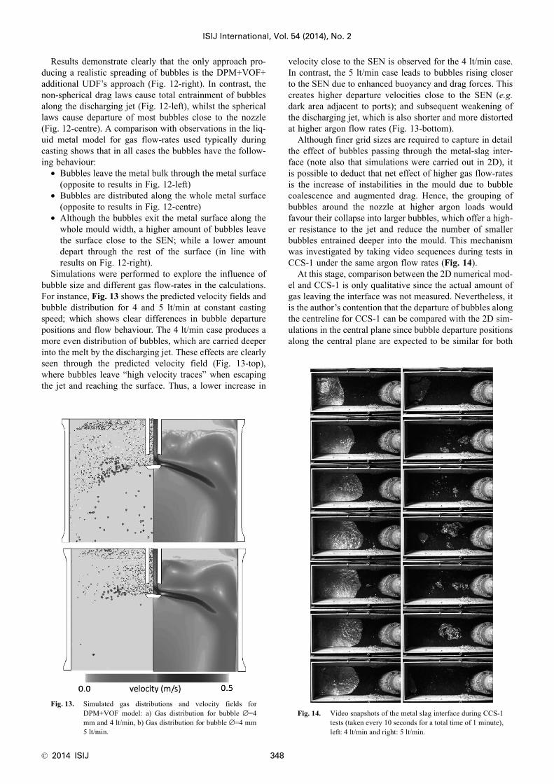
Simulations were performed to explore the influence ofbubble size and different gas flow-rates in the calculations.For instance, Fig. 13 shows the predicted velocity fields andbubble distribution for 4 and 5 lt/min at constant castingspeed; which shows clear differences in bubble departurepositions and flow behaviour. The 4 lt/min case produces amore even distribution of bubbles, which are carried deeperinto the melt by the discharging jet. These effects are clearlyseen through the predicted velocity field (Fig. 13-top),where bubbles leave “high velocity traces” when escapingthe jet and reaching the surface. Thus, a lower increase in
velocity close to the SEN is observed for the 4 lt/min case.In contrast, the 5 lt/min case leads to bubbles rising closerto the SEN due to enhanced buoyancy and drag forces. Thiscreates higher departure velocities close to the SEN (e.g.dark area adjacent to ports); and subsequent weakening ofthe discharging jet, which is also shorter and more distortedat higher argon flow rates (Fig. 13-bottom).
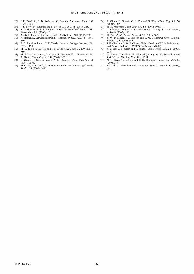
Although finer grid sizes are required to capture in detailthe effect of bubbles passing through the metal-slag inter-face (note also that simulations were carried out in 2D), itis possible to deduct that net effect of higher gas flow-ratesis the increase of instabilities in the mould due to bubblecoalescence and augmented drag. Hence, the grouping ofbubbles around the nozzle at higher argon loads wouldfavour their collapse into larger bubbles, which offer a high-er resistance to the jet and reduce the number of smallerbubbles entrained deeper into the mould. This mechanismwas investigated by taking video sequences during tests inCCS-1 under the same argon flow rates (Fig. 14).
At this stage, comparison between the 2D numerical mod-el and CCS-1 is only qualitative since the actual amount ofgas leaving the interface was not measured. Nevertheless, itis the author’s contention that the departure of bubbles alongthe centreline for CCS-1 can be compared with the 2D sim-ulations in the central plane since bubble departure positionsalong the central plane are expected to be similar for both
Fig. 13. Simulated gas distributions and velocity fields forDPM+VOF model: a) Gas distribution for bubble ∅=4mm and 4 lt/min, b) Gas distribution for bubble ∅=4 mm5 lt/min.
Fig. 14. Video snapshots of the metal slag interface during CCS-1tests (taken every 10 seconds for a total time of 1 minute),left: 4 lt/min and right: 5 lt/min.

ISIJ International, Vol. 54 (2014), No. 2
349 © 2014 ISIJ
cases. This is due to the fact that the entrainment of bubblesis strongly dependent on the discharging jet intensity; whilevelocities in the thickness direction are thought to have littleinfluence in the entrainment of bubbles. Differences in sta-bility of the metal surface are easily noticeable by compar-ing the video-sequences for 4 lt/min (left) and 5 lt/min(right) in Fig. 14. Lower argon flow rates produce a morestable flow pattern at the surface, with the formation of thetypical upper roll pushing constantly the oil layer towardsthe nozzle. In this case, argon bubbles depart uniformlyalong the mould width with smaller bubbles bursting closerto the narrow face; while slightly larger bubbles burst nextto the SEN. In contrast, the higher argon flow rate case pro-duces an unstable metal surface with some medium sizebubbles bursting at random positions and large bubblesexploding close to the SEN.
Not incidentally, this transition from stable to unstableflow was detected when increasing the argon flow rate high-er than 4 lt/min; which is the maximum gas flow rateemployed by operators to avoid a “boiling effect in the sur-face” This boiling effect is known to be detrimental tomould level control due to unstable metal flows (asobserved in the simulations and CCS-1). This demonstratesthat the numerical methodology developed is predictingaccurately the transition point from stable to unstable flowpatterns due to argon injection as seen in the liquid metalmodel CCS-1 and the daily casting practice. Application ofthese tools to find optimal argon flow rates and improvedprocess windows is an ongoing task by means of parametricstudies, further tests in CCS-1 and plant trials.25)
6. Conclusions
A novel numerical technique able to predict the multi-phase (steel/slag) flow dynamics coupled with argon injec-tion within the CC mould has been presented. The techniqueis based on the coupling of the DPM Lagrangian approach,which allows individual tracking of gas bubbles in a contin-uum phase; together with the Volume of Fluid method forcalculation of free surfaces on multiphase flows. The modelhas been developed with the aim of analysing industrialpractices (e.g. argon injection) by comparing results withphysical modelling in a Continuous Casting Simulator(CCS-1) and industrial observations. The following conclu-sions can be drawn from the initial application of these mod-els:
(1) The coupling of the DPM technique to an existingCC model based on the multiphase VOF method has provenpossible. This includes the displacement of bubbles acrossthe slag-metal interface and through the slag layers.
(2) The modified DPM+VOF model with additionalsource terms is the only capable of describing realisticallythe distribution of bubbles as seen in liquid metal modelexperiments and the industrial practice.
(3) Both the numerical and physical model presentedare capable of matching phenomena observed in the indus-trial practice such as the “boiling effect” at excessive argonflow rates, which is detrimental to process stability.
(4) The combination of predictions by the developednumerical model and observations in CCS-1 allow a deeperunderstanding of the mechanisms responsible for achieving
stable or unstable flows during casting.Findings provide enough evidence to consider the
DPM+VOF technique as reliable for the analysis of argoninjection in Continuous Casting. The model is thus ready forparametric studies and final coupling with heat transfer andsolidification on a fully integrated model for ContinuousCasting.
AcknowledgementsPRL would like to thank operators at SSAB for fruitful
discussions and Mr. Christer Olofsson for support duringCCS-1 trials. PJ would like to thank Professor Pär Jonssonat KTH (Stockholm) for continuing support during hisM.Sc. and Doctoral studies. PRL and PJ would like to thankProfessors K. Nakajima, S. Lohenkilpi and P. Jonsson fortheir kind invitation and excellent organization of CSSCR2013 in Helsinki-Stockholm. The research leading to theseresults has received funding from the European Union’sResearch Programme of the Research Fund for Coal andSteel (RFCS) under grant agreement n° [RFSR-CT-2011-00005].
REFERENCES
1) G. Stephens, D. Kirsch, M. Pianezzola, I. Alonso, V. Colla, J. Palaciosand T. Lamp: RFSR-CT-2009-00005, European-Comission, ResearchFund for Coal and Steel, Brussels, (2012).
2) P. Thomas: Mater. Sci. Technol., 21 (2005), 334.3) J. Ciriza, J. Laraudogoitia and G. Alvarez de Toledo: Ironmaking
Steelmaking, 30 (2003), 353.4) S. Kunstreich and P. H. Dauby: 4th European Conf. on Continuous
Casting, IOM3, London, (2002), 489.5) W. C. Amaral, L. Gimeno, A. Carvalho and F. Vartuli: Conf. Proc.
Annu. Symp.on Computer Architecture, ICAF·Pergamon Press,Düsseldorf, (1980), 301.
6) R. Aigner and H. Steinruck: Eurotherm, 82 (2005).7) B. Shen, H. Shen and B. Liu: ISIJ Int., 47 (2007), 427.8) P. E. Ramirez-Lopez, P. D. Lee and K. C. Mills: 12th Conf. Modeling
of Casting, Welding and Advanced Solidification Processes, TMS,Warrendale, PA, (2009), 61.
9) S. Louhenkilpi, M. Makinen, S. Vapalahti, T. Raisanen and J. Laine:Mater. Sci. Eng. A, 413–414 (2005), 135.
10) B. G. Thomas and C. Li: Metall. Mater. Trans. B, 35 (2004), 1151.11) B. G. Thomas: Metall. Mater. Trans. B, 33 (2002), 795.12) M. Wu, A. Ludwig and C. Pfeiler: Mater. Sci. Eng. A, Struct. Mater.,
413–414 (2005), 115.13) B. G. Thomas, A. Dennisov and H. Bai: ISS 80th Steelmaking Conf.,
ISS, Warrendale, PA, (1997).14) L. I. Baokuan, T. Okane and T. Umeda: Metall. Mater. Trans. B, 31
(2000), 1491.15) H. Bai and B. G. Thomas: Metall. Mater. Trans. B, 32B (2001), 269.16) P. E. Ramirez-Lopez, P. D. Lee, K. C. Mills, R. D. Morales, A. R.
Sanchez-Perez and A. Ramos-Banderas: 6th European Conf. onContinuous Casting, Associazione Italiana di Metalurgia, Riccione,(2008).
17) P. E. Ramirez Lopez, P. D. Lee and K. C. Mills: ISIJ Int., 50 (2010),425.
18) P. E. Ramirez-Lopez, P. D. Lee, K. C. Mills and B. Santillana: ISIJInt., 50 (2010), 1797.
19) K. Timmel, S. Eckert, G. Gerbeth, S. F. and T. Wondrak: ISIJ Int.,50 (2010), 1134.
20) D. J. Scoones, O. Puetz, U. Sjöström and J. M. Galpin: Rfcs, EUR20887, Research Fund for Coal and Steel, Brussels, (2003).
21) S. R. Higson, P. Drake, M. Lewus, T. Lamp, H. Kochner, P. Valentin,C. Bruch, J. Ciriza, J. Laraudogoitia, J. Björkvall and L. Bergman:EUR 24205, Research Fund for Coal and Steel, Brussels, (2010).
22) G. Gerbeth, S. Eckert, K. Timmel and X. Miao: Jim Evans HonorarySymp.: Flow Phenomena in Steel Continuous Casting, Sponsored byTMS, Wiley, NJ, (2010).
23) T. Weissenfluh: Int. J. Heat Mass Transfer, 28 (1985), 1563.24) M. Iguchi, M. Takeuchi, H. Kawabata, K. Ebina and Z. Morita:
Mater. Trans. JIM, 35 (1994), 716.25) P. E. Ramirez Lopez, J. Björkvall, T. Jonsson, S. Karagadde, P. D.
Lee, K. C. Mills, D. Van der Plas, E. Van Vliet, F. Shahbazian, P.Andersson, J. Oppelstrup, C. NIlsson and P. Wikström: RFSR-CT-2011-00005, European-Comission, Research Fund for Coal and Steel,Brussels, (2013).
© 2014 ISIJ 350
ISIJ International, Vol. 54 (2014), No. 2
26) J. U. Brackbill, D. B. Kothe and C. Zemach: J. Comput. Phys., 100(1992), 335.
27) J. L. Liow, M. Rudman and P. Liovic: ISIJ Int., 41 (2001), 225.28) R. D. Morales and P. E. Ramirez-Lopez: AISTech Conf. Proc., AIST,
Warrendale, PA, (2006), 20.29) ANSYS Fluent, v.12 - User’s Guide, ANSYS Inc., NH, (1995–2007).30) K. Spitzer, K. Schwerdtfeger and J. Holzhauser: Steel Res., 70 (1999),
430.31) P. E. Ramirez Lopez: PhD Thesis, Imperial College London, UK,
(2010), 170.32) M. V. Tabib, S. A. Roy and J. B. Joshi: Chem. Eng. J., 139 (2008),
589.33) M. E. Díaz, A. Iranzo, D. Cuadra, R. Barbero, F. J. Montes and M.
A. Galán: Chem. Eng. J., 139 (2008), 363.34) D. Zhang, N. G. Deen and J. A. M. Kuipers: Chem. Eng. Sci., 61
(2006), 7593.35) M. Cross, T. N. Croft, G. Djambazov and K. Pericleous: Appl. Math.
Model., 30 (2006), 1445.
36) E. Olmos, C. Gentric, C. C. Vial and G. Wild: Chem. Eng. Sci., 56(2001), 6359.
37) H. H. Jakobsen: Chem. Eng. Sci., 56 (2001), 1049.38) C. Pfeiler, M. Wu and A. Ludwig: Mater. Sci. Eng. A, Struct. Mater.,
413–414 (2005), 115.39) H. Bai: Metall. Mater. Trans. B, 32 (2001), 707.40) S. W. P. Cloete, J. J. Eksteen and S. M. Bradshaw: Prog. Comput.
Fluid Dy., 9 (2009), 345.41) J. E. Olsen and S. W. P. Cloete: 7th Int. Conf. on CFD in the Minerals
and Process Industries, CSIRO, Melbourne, (2009).42) S. Cloete, J. E. Olsen and P. Skjetne: Appl. Ocean Res., 31 (2009),
220.43) M. Iguchi, T. Chihara, N. Takanashi, Y. Ogawa, N. Tokumitsu and
Z.-i. Morita: ISIJ Int., 35 (1995), 1354.44) N. G. Deen, T. Solberg and B. H. Hjertager: Chem. Eng. Sci., 56
(2001), 6341.45) J. L. Xia, T. Ahokainen and L. Holappa: Scand. J. Metall., 30 (2001),
69.