Embed Size (px)
Citation preview
Turbo air Speeds Up the Pace of Innovation
Part No. KUCST2901
Refrigeration System
Installation & Operation Manual Please read this manual completely before attempting to install or operate this equipment !
Package Unit ( TOP MOUNT )
2
CONTENTS
Safety Information …………………………………… 3
Inspection ……………………………………………… 3
Locating SMART 7 Package Unit…………………… 6
Installation Procedure ………………………………… 8
Sequence of Operation ……………………………… 10
Controller Setting …………………………………… 11
System Troubleshooting …………………………… 19
Electrical Wiring Diagram…………………………… 20
3
Safety Information
Be sure all power sources are turned off before checking the electric wiring or
appliances to avoid electric shock.
Do not run fan if cover or case is removed. This is to avoid electric shock.
Keep finger away from moving parts.
Avoid touching refrigerant lines. Some parts are very hot and can cause burns.
Avoid contacting sharp edges or coil surface that are a potential injury hazard.
Avoid touching the units or electric box in wet hands to prevent electric shock.
Please call the specialized installation company or trained personnel when you installing,
moving, operating of the unit.
Field wiring must confirm to the requirements of units’ electric specification.
Inspection
A person at the job site to receive material holds responsibility. Each shipment should
be carefully inspected against the bill of lading. The shipping receipt should not be
signed before careful inspection. Check carefully for concealed damage. Any shortage
or damages should be reported to the delivering carrier. If damaged material becomes
the delivering carrier’s responsibility and it should not be returned to Turbo air unless
prior approval is given to do so. Check the serial tag information with invoice. Report
any discrepancies to Turbo air sales representatives.
4
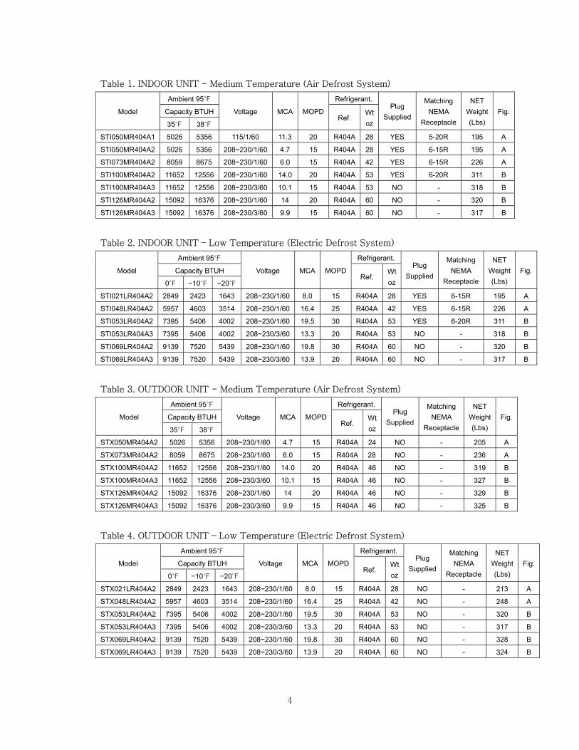
Table 1. INDOOR UNIT - Medium Temperature (Air Defrost System)
Model
Ambient 95℉
Voltage MCA MOPD
Refrigerant. Plug
Supplied
Matching NEMA
Receptacle
NET Weight (Lbs)
Fig. Capacity BTUH Ref.
Wt oz 35℉ 38℉
STI050MR404A1 5026 5356 115/1/60 11.3 20 R404A 28 YES 5-20R 195 A
STI050MR404A2 5026 5356 208~230/1/60 4.7 15 R404A 28 YES 6-15R 195 A
STI073MR404A2 8059 8675 208~230/1/60 6.0 15 R404A 42 YES 6-15R 226 A
STI100MR404A2 11652 12556 208~230/1/60 14.0 20 R404A 53 YES 6-20R 311 B
STI100MR404A3 11652 12556 208~230/3/60 10.1 15 R404A 53 NO - 318 B
STI126MR404A2 15092 16376 208~230/1/60 14 20 R404A 60 NO - 320 B
STI126MR404A3 15092 16376 208~230/3/60 9.9 15 R404A 60 NO - 317 B
Table 2. INDOOR UNIT – Low Temperature (Electric Defrost System)
Model
Ambient 95℉
Voltage MCA MOPD
Refrigerant. Plug
Supplied
Matching NEMA
Receptacle
NET Weight (Lbs)
Fig. Capacity BTUH Ref.
Wt oz 0℉ −10℉ −20℉
STI021LR404A2 2849 2423 1643 208~230/1/60 8.0 15 R404A 28 YES 6-15R 195 A
STI048LR404A2 5957 4603 3514 208~230/1/60 16.4 25 R404A 42 YES 6-15R 226 A
STI053LR404A2 7395 5406 4002 208~230/1/60 19.5 30 R404A 53 YES 6-20R 311 B
STI053LR404A3 7395 5406 4002 208~230/3/60 13.3 20 R404A 53 NO - 318 B
STI069LR404A2 9139 7520 5439 208~230/1/60 19.8 30 R404A 60 NO - 320 B
STI069LR404A3 9139 7520 5439 208~230/3/60 13.9 20 R404A 60 NO - 317 B
Table 3. OUTDOOR UNIT - Medium Temperature (Air Defrost System)
Model
Ambient 95℉
Voltage MCA MOPD
Refrigerant. Plug
Supplied
Matching NEMA
Receptacle
NET Weight (Lbs)
Fig. Capacity BTUH Ref.
Wt oz 35℉ 38℉
STX050MR404A2 5026 5356 208~230/1/60 4.7 15 R404A 24 NO - 205 A
STX073MR404A2 8059 8675 208~230/1/60 6.0 15 R404A 28 NO - 236 A
STX100MR404A2 11652 12556 208~230/1/60 14.0 20 R404A 46 NO - 319 B
STX100MR404A3 11652 12556 208~230/3/60 10.1 15 R404A 46 NO - 327 B
STX126MR404A2 15092 16376 208~230/1/60 14 20 R404A 46 NO - 329 B
STX126MR404A3 15092 16376 208~230/3/60 9.9 15 R404A 46 NO - 325 B
Table 4. OUTDOOR UNIT – Low Temperature (Electric Defrost System)
Model
Ambient 95℉
Voltage MCA MOPD
Refrigerant. Plug
Supplied
Matching NEMA
Receptacle
NET Weight (Lbs)
Fig. Capacity BTUH Ref.
Wt oz 0℉ −10℉ −20℉
STX021LR404A2 2849 2423 1643 208~230/1/60 8.0 15 R404A 28 NO - 213 A
STX048LR404A2 5957 4603 3514 208~230/1/60 16.4 25 R404A 42 NO - 248 A
STX053LR404A2 7395 5406 4002 208~230/1/60 19.5 30 R404A 53 NO - 320 B
STX053LR404A3 7395 5406 4002 208~230/3/60 13.3 20 R404A 53 NO - 317 B
STX069LR404A2 9139 7520 5439 208~230/1/60 19.8 30 R404A 60 NO - 328 B
STX069LR404A3 9139 7520 5439 208~230/3/60 13.9 20 R404A 60 NO - 324 B
5
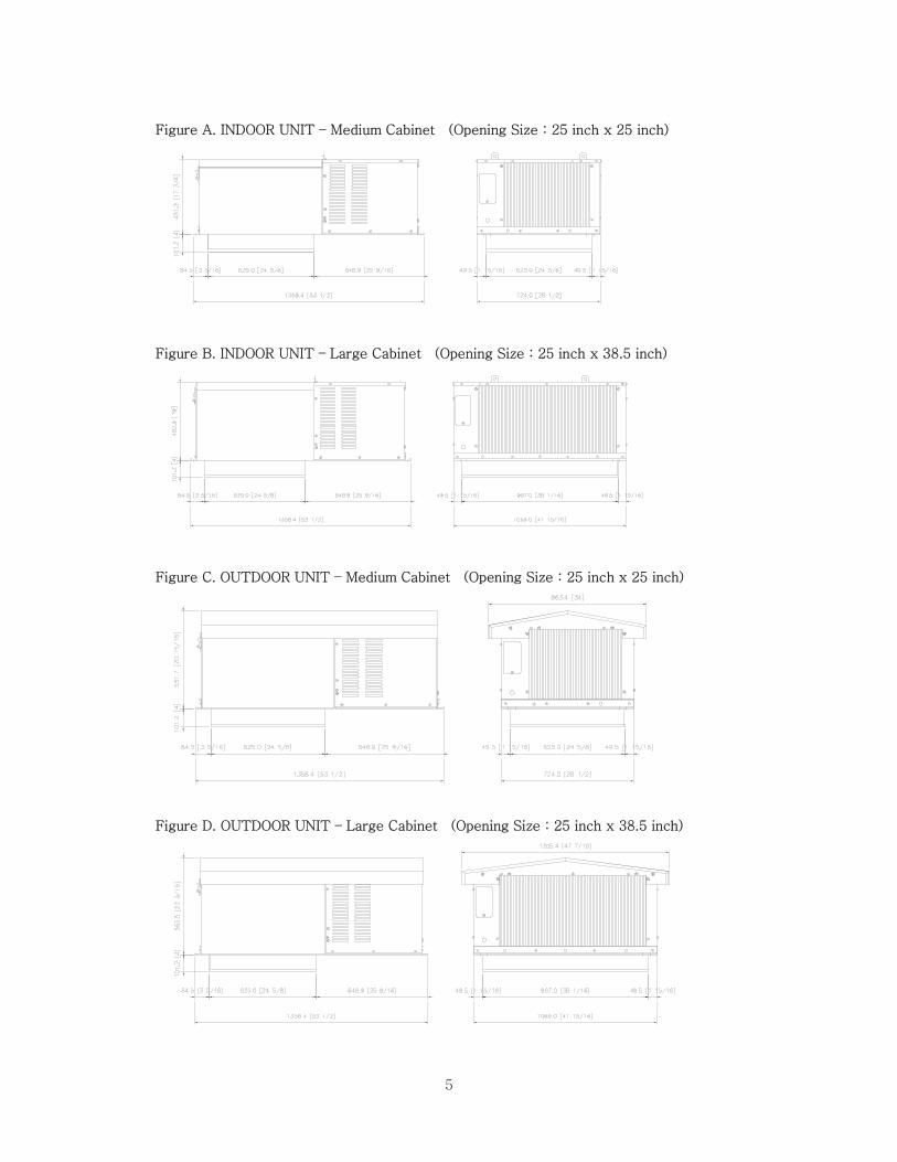
Figure A. INDOOR UNIT – Medium Cabinet (Opening Size : 25 inch x 25 inch)
Figure B. INDOOR UNIT – Large Cabinet (Opening Size : 25 inch x 38.5 inch)
Figure C. OUTDOOR UNIT – Medium Cabinet (Opening Size : 25 inch x 25 inch)
Figure D. OUTDOOR UNIT – Large Cabinet (Opening Size : 25 inch x 38.5 inch)

6
Locating SMART 7 Package Unit Unit Installation Requirements 1. You must ensure before unit placement on the roof of box that the structural strength of the
box can withstand the weight of SMART7 equipment
2. The unit should be installed away from noise sensitive site and must have proper support for
noise and vibration not to be transmitted into the building.
3. Unit must be located away from steam, hot air or heat generator and placement should be
selected in consideration of ventilation.
4. Indoor units are designed for indoor use only with ambient between 50℉~100℉ and have no
system control following ambient variation.
5. Evaporator section must not be located over doors.
6. Air circulation must cover completely inner space.
7. Installation, service and maintenance must be carried out by licensed contractor in conformity
with the local standard construction code.
Ignoring above requirement will result in system fault, shorten life span and void the warranty,
Unit Transport Requirements. 1. Do not remove shipping skid until ready to move it upon box rooftop.
2. Always watch out not to contact sharp edges and coil surfaces to avoid potential injury. Wear
safety gears always during installation.
3. Use spreader bar to lift the unit upon roof of box not to damage on the cabinet.
4. Do not remove compartment cover of the compressor section, hood for outdoor unit.
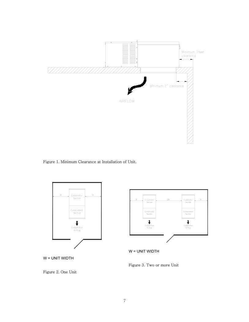
Unit Installation location. 1. Space between wall and air in/outlet must be secured at least 2inch.(refer to Fig. 1)
2. There must be 2 feet space secured at least above unit for service and removal of top
case.(Refer to Fig. 1)
3. Single unit installation must be carried out following Fig. 2.
4. Two or more unit installation must be carried out following Fig. 3.
7
Figure 1. Minimum Clearance at Installation of Unit.
W = UNIT WIDTH
Figure 2. One Unit
W = UNIT WIDTH
Figure 3. Two or more Unit
8
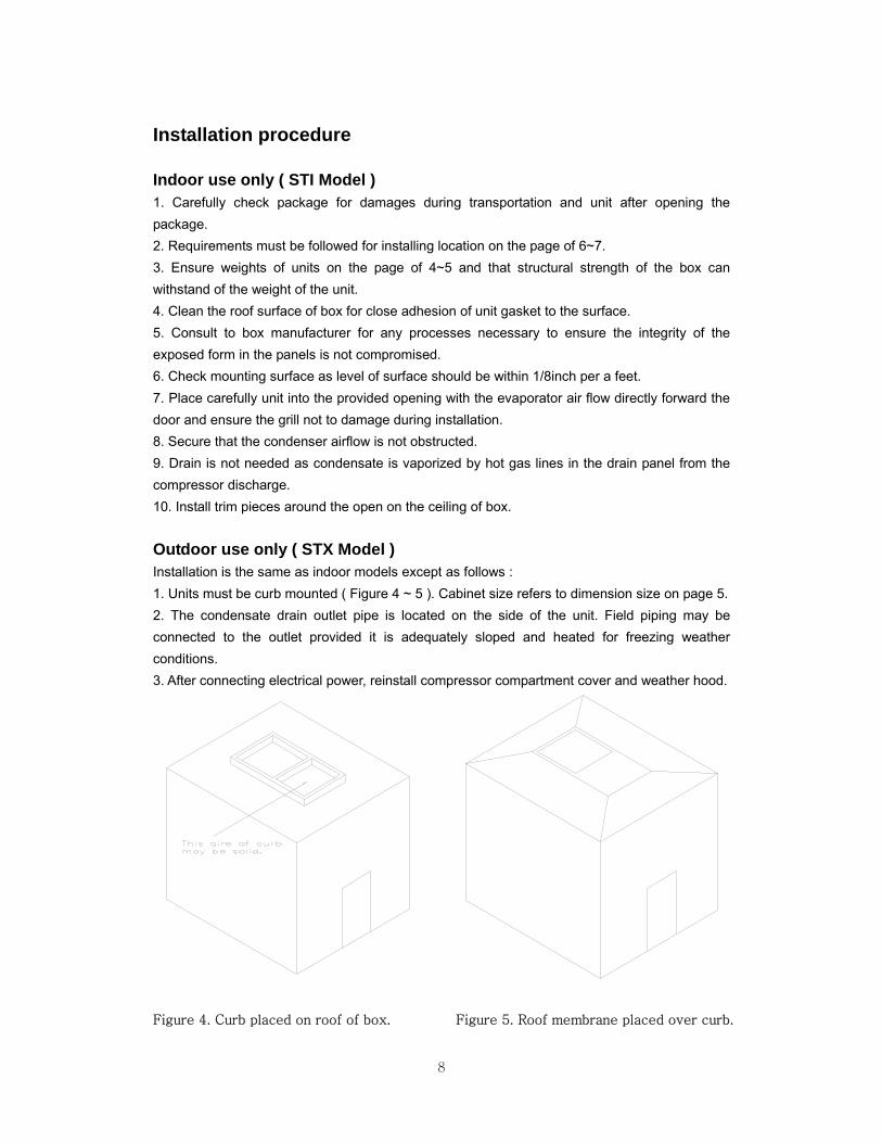
Installation procedure Indoor use only ( STI Model ) 1. Carefully check package for damages during transportation and unit after opening the package. 2. Requirements must be followed for installing location on the page of 6~7. 3. Ensure weights of units on the page of 4~5 and that structural strength of the box can withstand of the weight of the unit. 4. Clean the roof surface of box for close adhesion of unit gasket to the surface. 5. Consult to box manufacturer for any processes necessary to ensure the integrity of the exposed form in the panels is not compromised. 6. Check mounting surface as level of surface should be within 1/8inch per a feet. 7. Place carefully unit into the provided opening with the evaporator air flow directly forward the door and ensure the grill not to damage during installation. 8. Secure that the condenser airflow is not obstructed. 9. Drain is not needed as condensate is vaporized by hot gas lines in the drain panel from the compressor discharge. 10. Install trim pieces around the open on the ceiling of box. Outdoor use only ( STX Model ) Installation is the same as indoor models except as follows : 1. Units must be curb mounted ( Figure 4 ~ 5 ). Cabinet size refers to dimension size on page 5. 2. The condensate drain outlet pipe is located on the side of the unit. Field piping may be connected to the outlet provided it is adequately sloped and heated for freezing weather conditions. 3. After connecting electrical power, reinstall compressor compartment cover and weather hood.
Figure 4. Curb placed on roof of box.
Figure 5. Roof membrane placed over curb.
9
Check before Unit Start-up. 1. Check all electrical and refrigerant connections.
2. Observe all applicable building and electrical codes when wiring.
3. Make sure power supply has correct voltage and phase for unit and is fused properly.
4. If unit is connected with a power cord, use the cord with plug to connect to power supply.
If unit is not connected with a power cord, use hard wire to connect to power supply.
IMPORTANT
Do not use extension cords to connect unit to power.
Plug-in to grounded three prong outlet.
Do not remove grounding prong.
Do not use a power adapter.
5. All medium temperature models are preset to factory default settings as :
a) 3 hours of compressor runtime between defrosts.
b) Defrost termination temperature = 38 F / 3.5 C
6. All low Temperature Models are preset to factory default settings at table 4.
Standard Maintenance Guideline. After first year of operation and under normal usage, maintenance should cover the following
items at least once every six months.
1. Check all electrical and refrigerant connections.
2. Check all wiring and insulators.
3. Check contactors for proper operation and for state of contact points.
4. Check all fan motor. Tighten motor mount bolts, nuts and fan set screws.
5. Clean the heatexchanger (evaporator and condenser) coil surface.
6. Check the operation of the control system. Make sure all safety controls are operating
properly.
7. Check the defrost control system. Make sure all defrost controls are operating properly.
8. Check the drain pan and drain line. If necessary, clean the drain pan and drain line.
9. Check the all heaters. Make sure the crankcase and drain line heaters are operating properly.
After installation of unit, it must be checked at least once for proper defrosting. The amount and
pattern of frosting can vary considerably. It is dependent on the temperature of the room, the
type of product being stored, how often new product is brought into the room and how often
door is opened. Therefore, it may be necessary to periodically change the number of defrost
cycles or adjust the duration of defrost.
10
Sequence of Operation. Operation of Refrigeration. 1. When switch is turned on, power is provided to the temperature control, compressor,
condenser and evaporator fan motor. And they will run until the box temperature setting is
reached.
2. When the box temperature reaches a setting, the compressor and condenser fan motors shut
off while evaporator fan motor is working.
3. When the box temperature rises above the set point and minimum off-time has elapsed, the
compressor contactor will be re-energized and re-operated.
Operation of Defrost. 1. Under normal electric defrost operation, the temperature/defrost control will de-energize the
compressor contactor, evaporator fans and energize the defrost heaters. But under normal air
defrost operation, the control will de-energize the compressor contactor and keep an evaporator
fan motor working.
2. When the coil has defrosted completely and reached the preset coil sensor temperature,
defrost heater cuts off and fan delay / drip sequences begin.
3. The control energizes the compressor and condenser fan motor and they restart.
4. When the coil temperature reaches 35℉ or fan delay time has elapsed, the evaporator fans
will be energized and started.
11
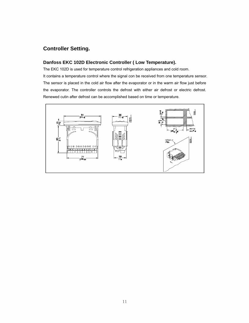
Controller Setting. Danfoss EKC 102D Electronic Controller ( Low Temperature). The EKC 102D is used for temperature control refrigeration appliances and cold room.
It contains a temperature control where the signal con be received from one temperature sensor.
The sensor is placed in the cold air flow after the evaporator or in the warm air flow just before
the evaporator. The controller controls the defrost with either air defrost or electric defrost.
Renewed cutin after defrost can be accomplished based on time or temperature.
12
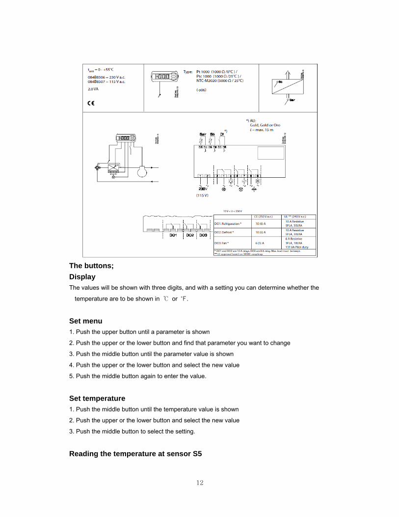
The buttons; Display The values will be shown with three digits, and with a setting you can determine whether the
temperature are to be shown in ℃ or ℉.
Set menu 1. Push the upper button until a parameter is shown
2. Push the upper or the lower button and find that parameter you want to change
3. Push the middle button until the parameter value is shown
4. Push the upper or the lower button and select the new value
5. Push the middle button again to enter the value.
Set temperature 1. Push the middle button until the temperature value is shown
2. Push the upper or the lower button and select the new value
3. Push the middle button to select the setting.
Reading the temperature at sensor S5
13
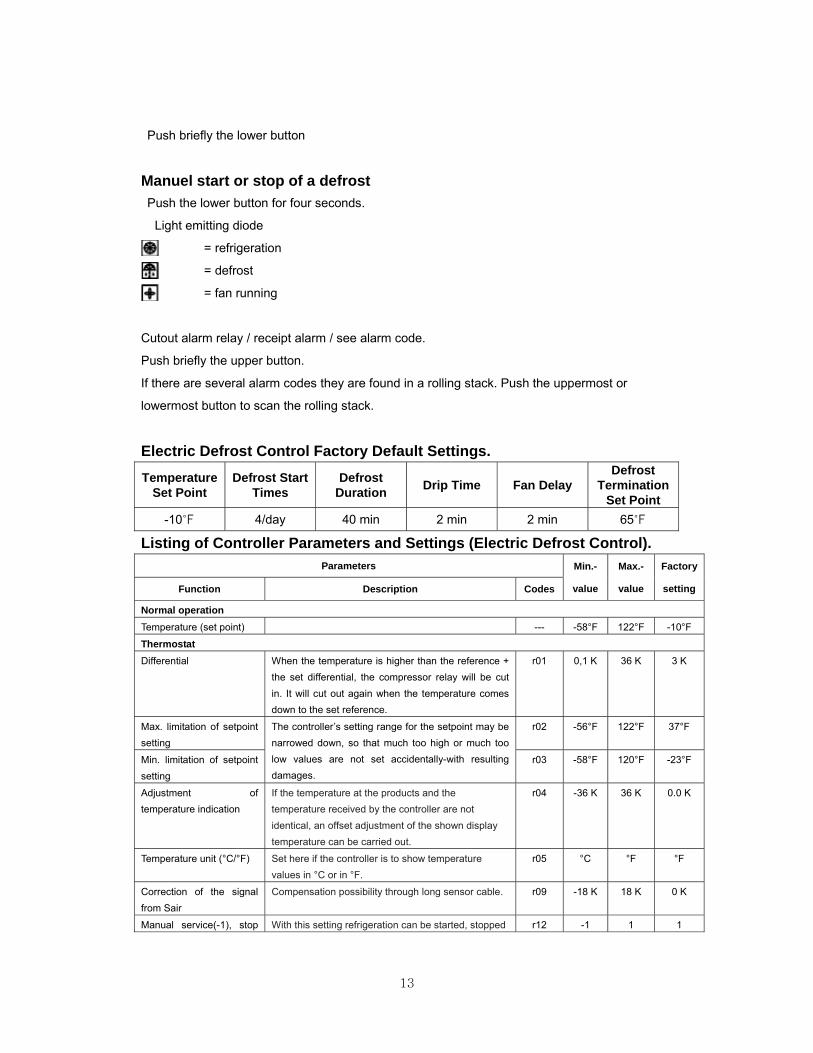
Push briefly the lower button
Manuel start or stop of a defrost Push the lower button for four seconds.
Light emitting diode
= refrigeration
= defrost
= fan running
Cutout alarm relay / receipt alarm / see alarm code.
Push briefly the upper button.
If there are several alarm codes they are found in a rolling stack. Push the uppermost or
lowermost button to scan the rolling stack.
Electric Defrost Control Factory Default Settings. Temperature
Set Point Defrost Start
Times Defrost
Duration Drip Time Fan Delay Defrost
Termination Set Point
-10℉ 4/day 40 min 2 min 2 min 65℉
Listing of Controller Parameters and Settings (Electric Defrost Control). Parameters Min.-
value
Max.-
value
Factory
setting Function Description Codes
Normal operation
Temperature (set point) --- -58°F 122°F -10°F
Thermostat Differential When the temperature is higher than the reference +
the set differential, the compressor relay will be cut in. It will cut out again when the temperature comes down to the set reference.
r01 0,1 K 36 K 3 K
Max. limitation of setpoint setting
The controller’s setting range for the setpoint may be narrowed down, so that much too high or much too low values are not set accidentally-with resulting damages.
r02 -56°F 122°F 37°F
Min. limitation of setpoint setting
r03 -58°F 120°F -23°F
Adjustment of temperature indication
If the temperature at the products and the temperature received by the controller are not identical, an offset adjustment of the shown display temperature can be carried out.
r04 -36 K 36 K 0.0 K
Temperature unit (°C/°F) Set here if the controller is to show temperature values in °C or in °F.
r05 °C °F °F
Correction of the signal from Sair
Compensation possibility through long sensor cable. r09 -18 K 18 K 0 K
Manual service(-1), stop With this setting refrigeration can be started, stopped r12 -1 1 1
14
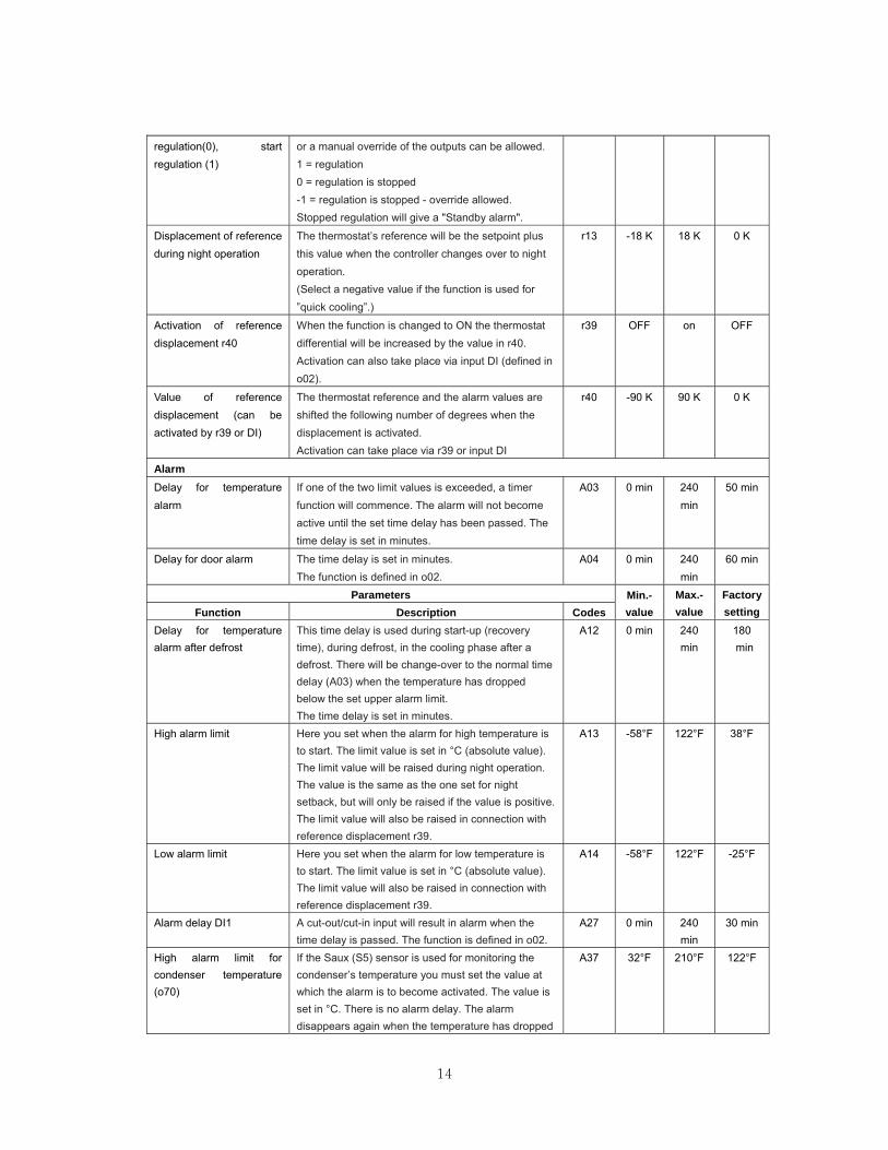
regulation(0), start regulation (1)
or a manual override of the outputs can be allowed. 1 = regulation 0 = regulation is stopped -1 = regulation is stopped - override allowed. Stopped regulation will give a "Standby alarm".
Displacement of reference during night operation
The thermostat’s reference will be the setpoint plus this value when the controller changes over to night operation. (Select a negative value if the function is used for ”quick cooling”.)
r13 -18 K 18 K 0 K
Activation of reference displacement r40
When the function is changed to ON the thermostat differential will be increased by the value in r40. Activation can also take place via input DI (defined in o02).
r39 OFF on OFF
Value of reference displacement (can be activated by r39 or DI)
The thermostat reference and the alarm values are shifted the following number of degrees when the displacement is activated. Activation can take place via r39 or input DI
r40 -90 K 90 K 0 K
Alarm
Delay for temperature alarm
If one of the two limit values is exceeded, a timer function will commence. The alarm will not become active until the set time delay has been passed. The time delay is set in minutes.
A03 0 min 240 min
50 min
Delay for door alarm The time delay is set in minutes. The function is defined in o02.
A04 0 min 240 min
60 min
Parameters Min.-value
Max.-value
Factory setting Function Description Codes
Delay for temperature alarm after defrost
This time delay is used during start-up (recovery time), during defrost, in the cooling phase after a defrost. There will be change-over to the normal time delay (A03) when the temperature has dropped below the set upper alarm limit. The time delay is set in minutes.
A12 0 min 240 min
180 min
High alarm limit Here you set when the alarm for high temperature is to start. The limit value is set in °C (absolute value). The limit value will be raised during night operation. The value is the same as the one set for night setback, but will only be raised if the value is positive. The limit value will also be raised in connection with reference displacement r39.
A13 -58°F 122°F 38°F
Low alarm limit Here you set when the alarm for low temperature is to start. The limit value is set in °C (absolute value). The limit value will also be raised in connection with reference displacement r39.
A14 -58°F 122°F -25°F
Alarm delay DI1 A cut-out/cut-in input will result in alarm when the time delay is passed. The function is defined in o02.
A27 0 min 240 min
30 min
High alarm limit for condenser temperature (o70)
If the Saux (S5) sensor is used for monitoring the condenser’s temperature you must set the value at which the alarm is to become activated. The value is set in °C. There is no alarm delay. The alarm disappears again when the temperature has dropped
A37 32°F 210°F 122°F
15
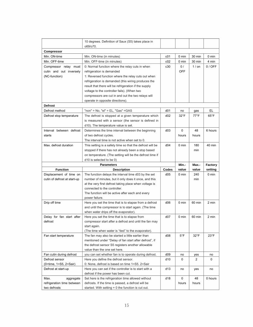
10 degrees. Definition of Saux (S5) takes place in o69/o70.
Compressor Min. ON-time Min. ON-time (in minutes) c01 0 min 30 min 0 min Min. OFF-time Min. OFF-time (in minutes) c02 0 min 30 min 4 min Compressor relay must cutin and out inversely (NC-function)
0: Normal function where the relay cuts in when refrigeration is demanded 1: Reversed function where the relay cuts out when refrigeration is demanded (this wiring produces the result that there will be refrigeration if the supply voltage to the controller fails). (When two compressors are cut in and out the two relays will operate in opposite directions).
c30 0 / OFF
1 / on 0 / OFF
Defrost Defrost method "non" = No, "el" = EL, "Gas" =GAS d01 no gas EL Defrost stop temperature The defrost is stopped at a given temperature which
is measured with a sensor (the sensor is defined in d10). The temperature value is set.
d02 32°F 77°F 65°F
Interval between defrost starts
Determines the time interval between the beginning of two defrost cycles. The interval time is not active when set to 0.
d03 0 hours
48 hours
6 hours
Max. defrost duration This setting is a safety time so that the defrost will be stopped if there has not already been a stop based on temperature. (The setting will be the defrost time if d10 is selected to be 0)
d04 0 min 180 min
40 min
Parameters Min.-value
Max.-value
Factory setting Function Description Codes
Displacement of time on cutin of defrost at start-up
The function delays the interval time d03 by the set number of minutes, but it only does it once, and this at the very first defrost taking place when voltage is connected to the controller. The function will be active after each and every power failure.
d05 0 min 240 min
0 min
Drip off time Here you set the time that is to elapse from a defrost and until the compressor is to start again. (The time when water drips off the evaporator).
d06 0 min 60 min 2 min
Delay for fan start after defrost
Here you set the time that is to elapse from compressor start after a defrost and until the fan may start again. (The time when water is “tied” to the evaporator).
d07 0 min 60 min 2 min
Fan start temperature The fan may also be started a little earlier than mentioned under “Delay of fan start after defrost”, if the defrost sensor S5 registers another allowable value than the one set here.
d08 5°F 32°F 23°F
Fan cutin during defrost you can set whether fan is to operate during defrost. d09 no yes no Defrost sensor (0=time, 1=S5, 2=Sair)
Here you define the defrost sensor. 0: None, defrost is based on time 1=S5. 2=Sair
d10 0 2 0
Defrost at start-up Here you can set if the controller is to start with a defrost if the power has been cut.
d13 no yes no
Max. aggregate refrigeration time between two defrosts
Set here is the refrigeration time allowed without defrosts. If the time is passed, a defrost will be started. With setting = 0 the function is cut out.
d18 0 hours
48 hours
0 hours
16
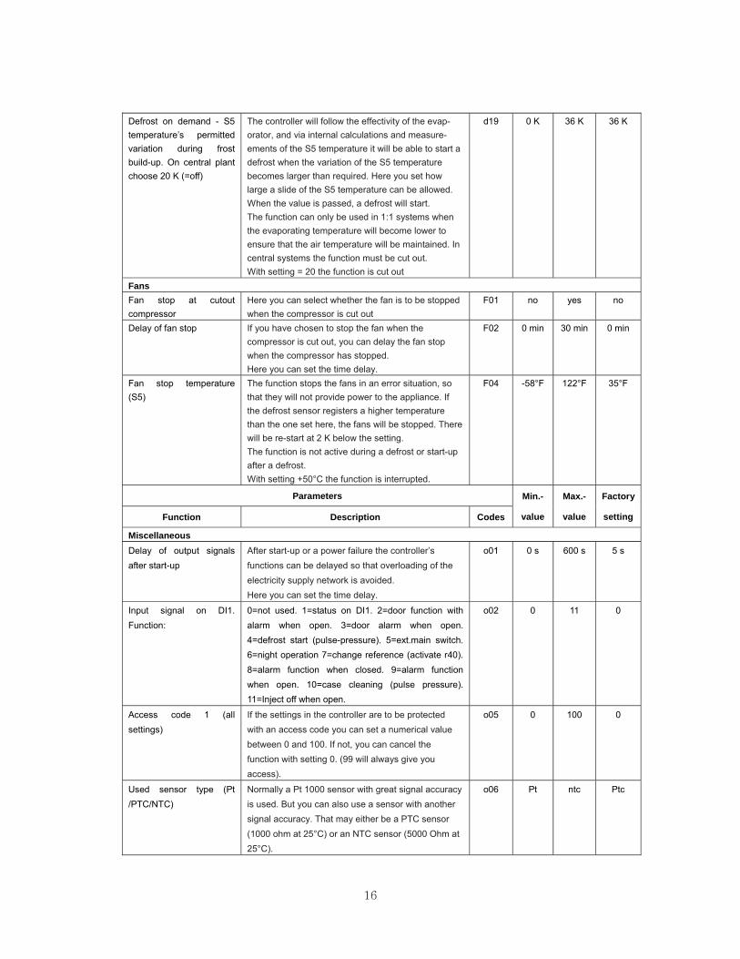
Defrost on demand - S5 temperature’s permitted variation during frost build-up. On central plant choose 20 K (=off)
The controller will follow the effectivity of the evap-orator, and via internal calculations and measure-ements of the S5 temperature it will be able to start a defrost when the variation of the S5 temperature becomes larger than required. Here you set how large a slide of the S5 temperature can be allowed. When the value is passed, a defrost will start. The function can only be used in 1:1 systems when the evaporating temperature will become lower to ensure that the air temperature will be maintained. In central systems the function must be cut out. With setting = 20 the function is cut out
d19 0 K 36 K 36 K
Fans Fan stop at cutout compressor
Here you can select whether the fan is to be stopped when the compressor is cut out
F01 no yes no
Delay of fan stop If you have chosen to stop the fan when the compressor is cut out, you can delay the fan stop when the compressor has stopped. Here you can set the time delay.
F02 0 min 30 min 0 min
Fan stop temperature (S5)
The function stops the fans in an error situation, so that they will not provide power to the appliance. If the defrost sensor registers a higher temperature than the one set here, the fans will be stopped. There will be re-start at 2 K below the setting. The function is not active during a defrost or start-up after a defrost. With setting +50°C the function is interrupted.
F04 -58°F 122°F 35°F
Parameters Min.-
value
Max.-
value
Factory
setting Function Description Codes
Miscellaneous Delay of output signals after start-up
After start-up or a power failure the controller’s functions can be delayed so that overloading of the electricity supply network is avoided. Here you can set the time delay.
o01 0 s 600 s 5 s
Input signal on DI1. Function:
0=not used. 1=status on DI1. 2=door function with alarm when open. 3=door alarm when open. 4=defrost start (pulse-pressure). 5=ext.main switch. 6=night operation 7=change reference (activate r40). 8=alarm function when closed. 9=alarm function when open. 10=case cleaning (pulse pressure). 11=Inject off when open.
o02 0 11 0
Access code 1 (all settings)
If the settings in the controller are to be protected with an access code you can set a numerical value between 0 and 100. If not, you can cancel the function with setting 0. (99 will always give you access).
o05 0 100 0
Used sensor type (Pt /PTC/NTC)
Normally a Pt 1000 sensor with great signal accuracy is used. But you can also use a sensor with another signal accuracy. That may either be a PTC sensor (1000 ohm at 25°C) or an NTC sensor (5000 Ohm at 25°C).
o06 Pt ntc Ptc
17
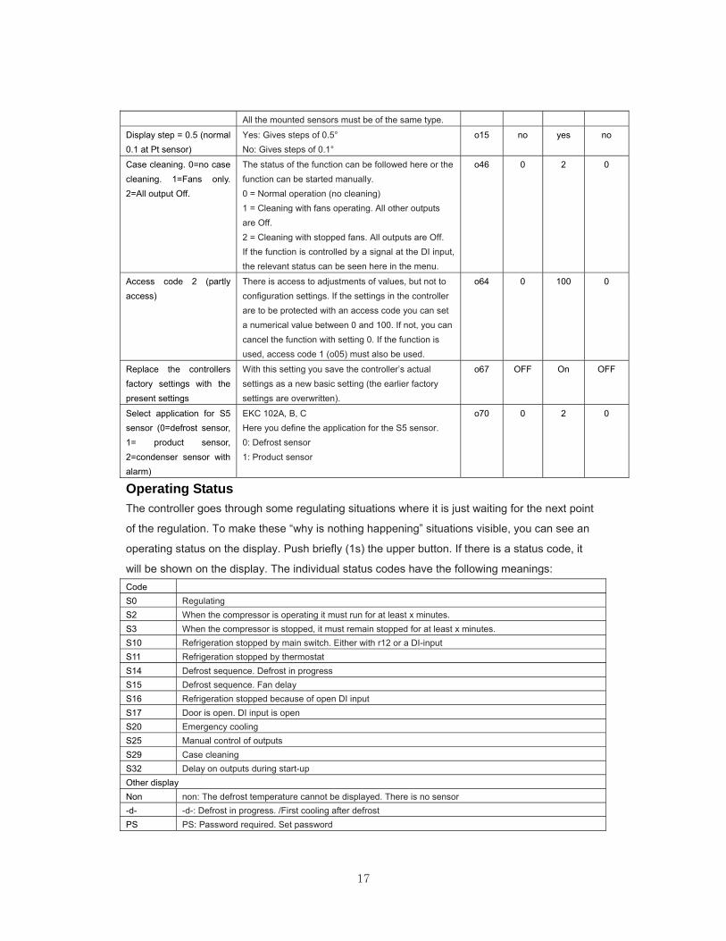
All the mounted sensors must be of the same type.
Display step = 0.5 (normal 0.1 at Pt sensor)
Yes: Gives steps of 0.5° No: Gives steps of 0.1°
o15 no yes no
Case cleaning. 0=no case cleaning. 1=Fans only. 2=All output Off.
The status of the function can be followed here or the function can be started manually. 0 = Normal operation (no cleaning) 1 = Cleaning with fans operating. All other outputs are Off. 2 = Cleaning with stopped fans. All outputs are Off. If the function is controlled by a signal at the DI input, the relevant status can be seen here in the menu.
o46 0 2 0
Access code 2 (partly access)
There is access to adjustments of values, but not to configuration settings. If the settings in the controller are to be protected with an access code you can set a numerical value between 0 and 100. If not, you can cancel the function with setting 0. If the function is used, access code 1 (o05) must also be used.
o64 0 100 0
Replace the controllers factory settings with the present settings
With this setting you save the controller’s actual settings as a new basic setting (the earlier factory settings are overwritten).
o67 OFF On OFF
Select application for S5 sensor (0=defrost sensor, 1= product sensor, 2=condenser sensor with alarm)
EKC 102A, B, C Here you define the application for the S5 sensor. 0: Defrost sensor 1: Product sensor
o70 0 2 0
Operating Status The controller goes through some regulating situations where it is just waiting for the next point
of the regulation. To make these “why is nothing happening” situations visible, you can see an
operating status on the display. Push briefly (1s) the upper button. If there is a status code, it
will be shown on the display. The individual status codes have the following meanings: Code S0 Regulating S2 When the compressor is operating it must run for at least x minutes. S3 When the compressor is stopped, it must remain stopped for at least x minutes. S10 Refrigeration stopped by main switch. Either with r12 or a DI-input S11 Refrigeration stopped by thermostat S14 Defrost sequence. Defrost in progress S15 Defrost sequence. Fan delay S16 Refrigeration stopped because of open DI input S17 Door is open. DI input is open S20 Emergency cooling S25 Manual control of outputs S29 Case cleaning S32 Delay on outputs during start-up Other display Non non: The defrost temperature cannot be displayed. There is no sensor -d- -d-: Defrost in progress. /First cooling after defrost PS PS: Password required. Set password
18
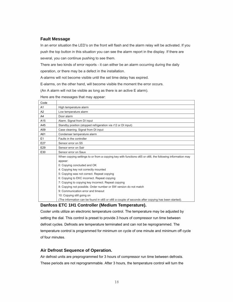
Fault Message In an error situation the LED’s on the front will flash and the alarm relay will be activated. If you
push the top button in this situation you can see the alarm report in the display. If there are
several, you can continue pushing to see them.
There are two kinds of error reports - it can either be an alarm occurring during the daily
operation, or there may be a defect in the installation.
A-alarms will not become visible until the set time delay has expired.
E-alarms, on the other hand, will become visible the moment the error occurs.
(An A alarm will not be visible as long as there is an active E alarm).
Here are the messages that may appear: Code A1 High temperature alarm A2 Low temperature alarm A4 Door alarm A15 Alarm. Signal from DI input A45 Standby position (stopped refrigeration via r12 or DI input) A59 Case cleaning. Signal from DI input A61 Condenser temperature alarm E1 Faults in the controller E27 Sensor error on S5 E29 Sensor error on Sair E30 Sensor error on Saux When copying settings to or from a copying key with functions o65 or o66, the following information may
appear: 0: Copying concluded and OK 4: Copying key not correctly mounted 5: Copying was not correct. Repeat copying 6: Copying to EKC incorrect. Repeat copying 7: Copying to copying key incorrect. Repeat copying 8: Copying not possible. Order number or SW version do not match 9: Communication error and timeout 10: Copying still going on (The information can be found in o65 or o66 a couple of seconds after copying has been started).
Danfoss ETC 1H1 Controller (Medium Temperature). Cooler units utilize an electronic temperature control. The temperature may be adjusted by
setting the dial. This control is preset to provide 3 hours of compressor run time between
defrost cycles. Defrosts are temperature terminated and can not be reprogrammed. The
temperature control is programmed for minimum on cycle of one minute and minimum off cycle
of four minutes.
Air Defrost Sequence of Operation. Air defrost units are preprogrammed for 3 hours of compressor run time between defrosts.
These periods are not reprogrammable. After 3 hours, the temperature control will turn the
19
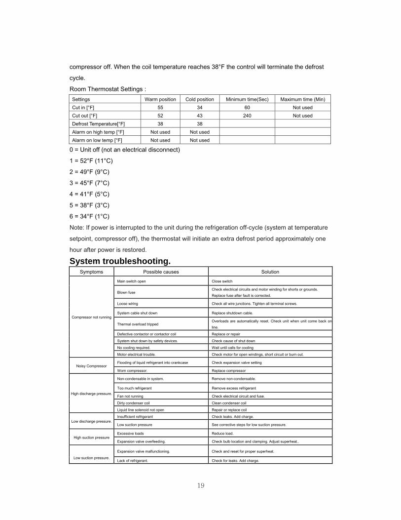
compressor off. When the coil temperature reaches 38°F the control will terminate the defrost
cycle.
Room Thermostat Settings : Settings Warm position Cold position Minimum time(Sec) Maximum time (Min) Cut in [°F] 55 34 60 Not used Cut out [°F] 52 43 240 Not used Defrost Temperature[°F] 38 38 Alarm on high temp [°F] Not used Not used Alarm on low temp [°F] Not used Not used
0 = Unit off (not an electrical disconnect)
1 = 52°F (11°C)
2 = 49°F (9°C)
3 = 45°F (7°C)
4 = 41°F (5°C)
5 = 38°F (3°C)
6 = 34°F (1°C)
Note: If power is interrupted to the unit during the refrigeration off-cycle (system at temperature
setpoint, compressor off), the thermostat will initiate an extra defrost period approximately one
hour after power is restored.
System troubleshooting. Symptoms Possible causes Solution
Compressor not running
Main switch open Close switch
Blown fuse Check electrical circuits and motor winding for shorts or grounds. Replace fuse after fault is corrected.
Loose wiring Check all wire junctions. Tighten all terminal screws.
System cable shut down Replace shutdown cable.
Thermal overload tripped Overloads are automatically reset. Check unit when unit come back on
line.
Defective contactor or contactor coil Replace or repair
System shut down by safety devices. Check cause of shut down
No cooling required. Wait until calls for cooling
Motor electrical trouble. Check motor for open windings, short circuit or burn out.
Noisy Compressor Flooding of liquid refrigerant into crankcase Check expansion valve setting
Worn compressor. Replace compressor
High discharge pressure.
Non-condensable in system. Remove non-condensable.
Too much refrigerant Remove excess refrigerant
Fan not running Check electrical circuit and fuse.
Dirty condenser coil Clean condenser coil
Liquid line solenoid not open Repair or replace coil
Low discharge pressure. Insufficient refrigerant Check leaks. Add charge.
Low suction pressure See corrective steps for low suction pressure.
High suction pressure Excessive loads Reduce load.
Expansion valve overfeeding. Check bulb location and clamping. Adjust superheat..
Low suction pressure.
Expansion valve malfunctioning. Check and reset for proper superheat.
Lack of refrigerant. Check for leaks. Add charge.
20
Evaporator dirty or iced. Clean. Check defrost parameters and modify as required.
Compressor thermal
protector switch open.
Evaporator dirty or iced Clean and defrost.
Condenser coil dirty. Clean. coil
Too much refrigerant Remove excess refrigerant
Clogged liquid line filter drier. Replace filter drier.
Operating beyond design conditions Add facilities so that conditions are within allowable limits.
Fan(s) will not operate
Main swich open. Close switch.
Blown fuses. Replace fuses. Check for short circuits or overload conditions.
Defective motor Replace motor.
Coil does not get cold enough to reset thermostat. Adjust fan delay setting of control.
Controller or sensor defective. Replace defective component.
Unit in defrost cycle. Wait for completion of cycle.
Room temperature too
high.
Controller temperature set too high. Adjust control
Superheat too high. Check and reset for proper superheat
Insufficient refrigerant Check leaks. Add charge
Evaporator coil iced Manually defrost coil. Check defrost controls for malfunction.
Ice accumulating on
ceiling around grill.
Defrost duration is too long. Adjust defrost termination temperature.
Fan delay not delaying fans after defrost period. Adjust fan delay setting or replace sensor.
Defective defrost control or sensor. Replace defective component.
Too many defrost. Adjust number of defrosts.
Coil not clearing of frost
during defrost cycle.
Coil temperature not getting above freezing point
during defrost. Check heater operation.
Not enough defrost cycles per day. Adjust control for more defrost cycles.
Defrost cycle too short. Adjust defrost control, defrost duration setting.
Defective defrost control or sensor. Replace defective component.
Ice accumulating in drain pan.
Defective heaters. Replace heater.
Unit not installed properly (out of level) Check and adjust if necessary.
Drain line plugged. Clean drain line.
Defective control. Replace defective component.
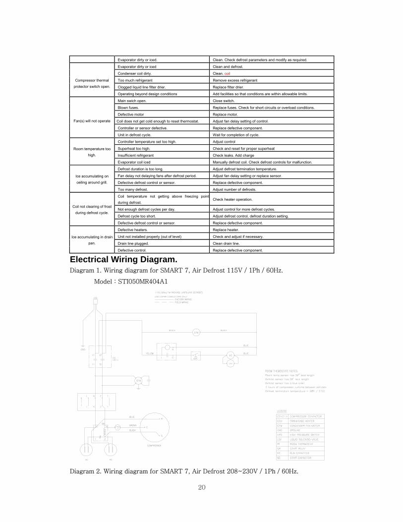
Electrical Wiring Diagram. Diagram 1. Wiring diagram for SMART 7, Air Defrost 115V / 1Ph / 60Hz.
Model : STI050MR404A1
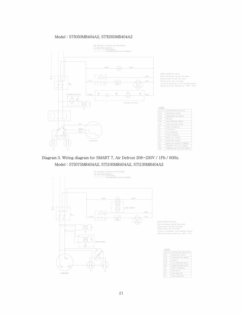
Diagram 2. Wiring diagram for SMART 7, Air Defrost 208~230V / 1Ph / 60Hz.
21
Model : STI050MR404A2, STX050MR404A2
Diagram 3. Wiring diagram for SMART 7, Air Defrost 208~230V / 1Ph / 60Hz.
Model : STI075MR404A2, STI100MR404A2, STI130MR404A2

22
Diagram4. Wiring diagram for SMART 7, Air Defrost 208~230V / 1Ph / 60Hz.
Model : STX075MR404A2 , STX100MR404A2 , STX130MR404A2
Diagram5. Wiring diagram for SMART 7, Air Defrost 208~230V / 3Ph / 60Hz.
Model : STI100MR404A3, STI130MR404A3, STX100MR404A3, STX130MR404A3
23
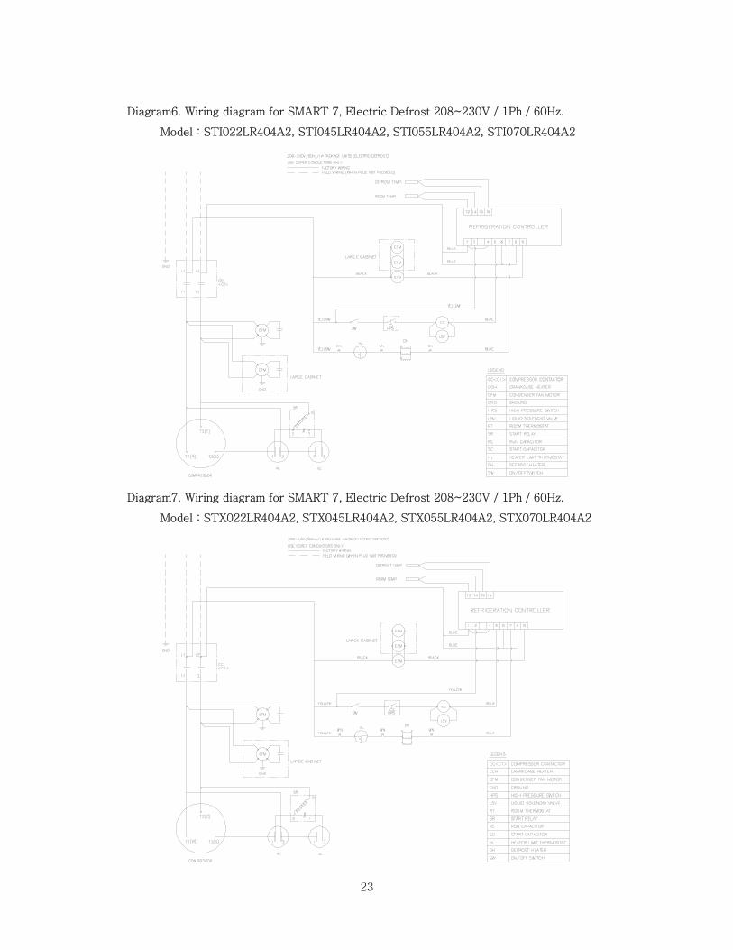
Diagram6. Wiring diagram for SMART 7, Electric Defrost 208~230V / 1Ph / 60Hz.
Model : STI022LR404A2, STI045LR404A2, STI055LR404A2, STI070LR404A2
Diagram7. Wiring diagram for SMART 7, Electric Defrost 208~230V / 1Ph / 60Hz.
Model : STX022LR404A2, STX045LR404A2, STX055LR404A2, STX070LR404A2

24
Diagram8. Wiring diagram for SMART 7, Electric Defrost 208~230V / 3Ph / 60Hz.
Model : STI055LR404A3 , STI070LR404A3 , STX055LR404A3 , STX070LR404A3
25
1250 Victoria street
CARSON, CA 90746
TEL : 310-900-1000
FAX : 310-900-1077
Toll Free : 1-800-381-7770
1-800-627-0032
(U.S.A & Canada)
http://www.turboairinc.com