Embed Size (px)
Citation preview
Regulation No. 123
Uniform provisions concerning the approval of adaptive front-lighting systems
(AFS) for motor vehicles
Contents
協定規則第123号
自動車用配光可変型前照灯システム(AFS)の認可に関する統一規定
目次
Regulation
A. Administrative provisions
0. Scope
1. Definitions
2. Application for approval of a system
3. Markings
4. Approval
B. Technical requirements for systems
5. General specifications
6. Illumination
7. Colour
C. Further administrative provisions
8. Modification of the system type and extension of approval
9. Conformity of production
10. Penalties for non-conformity of production
11. Production definitely discontinued
12. Names and addresses of Technical Services responsible for conducting approval
tests and of Administrative Departments
13. Transitional provisions
Annexes
1 Communication concerning the approval or refusal or extension or withdrawal of
規則
A. 行政規定
0. 適用範囲
1. 定義
2. システムの認可申請
3. 表示等
4. 認可
B. システムの技術要件
5. 一般仕様
6. 照明
7. 色
C. 補足的な行政規定
8. システムの型式の変更及び認可の拡大
9. 生産の適合性
10. 生産の不適合に対する罰則
11. 生産中止
12. 認可試験を担当する技術機関及び行政官庁の名称及び所在地
13. 過渡規定
附則
附則1 協定規則第123号に基づく、システムの型式の認可、認可拒否、認可拡
approval or production definitely discontinued of a type of system pursuant to
Regulation No. 123
2 Examples of arrangements of approval marks
3 Passing beam photometric requirements
4 Tests for stability of photometric performance of systems in operation
5 Minimum requirements for conformity of production control procedures
6 Requirements for systems incorporating lenses of plastic material - Testing of lens
or material samples and complete systems or part(s) of systems
Appendix 1 - Chronological order of approval tests
Appendix 2 - Method of measurement of the diffusion and transmission of light
Appendix 3 - Spray testing method
Appendix 4 - Adhesive tape adherence test
7 Minimum requirements for sampling by an inspector
8 Passing beam "cut-off" and aiming provisions
9 Photometric measurement provisions
10 Description forms
11 Requirements for LED modules and adaptive front-lighting systems (AFS)
including LED modules
大、認可取消又は生産中止に関する通知
附則2 認可マークの配置例
附則3 すれ違い用ビームの配光要件
附則4 点灯中のシステムの配光性能の安定性に関する試験
附則5 生産の適合性管理手順に関する最小要件
附則6 プラスチック材料のレンズを組み込んだシステムの要件—レンズ又は
供試材料及び完全なシステム又はシステムの部品の試験
付録1−認可試験の操作順
付録2−光の拡散と透過の測定方法
付録3−噴霧試験方法
付録4−接着テープによる接着試験
附則7 検査官による抜取検査の最小要件
附則8 すれ違い用ビームの「カットオフ」と照準調整の規定
附則9 配光測定規定
附則10 説明書式
附則 11 LED モジュール及び LED モジュール内蔵配光可変型前照灯システム
(AFS)に関する要件
A. Administrative provisions A. 行政規定
0. Scope
This Regulation applies to adaptive front-lighting systems (AFS) for motor vehicles
of categories M and N1.
1 As defined in Annex 7 to the Consolidated Resolution on the Construction of
0. 適用範囲
本規則は、M及びN1区分の自動車用配光可変型前照灯システム(AFS)に適
用する。
1 車両構造統合決議(R.E.3)の附則 7 の定義による(Amend.4 による最新改訂
Vehicles (R.E.3), (document TRANS/WP.29/78/Rev.1/Amend.2 as last amended by
Amend.4).
が実施された文書 TRANS/WP.29/78/Rev.1/Amend.2)。
1. Definitions
For the purpose of this Regulation:
1. 定義
本規則の目的においては、
1.1.
The definitions given in Regulation No. 48 and its series of amendments in force at
the time of application for type approval shall apply;
1.1.
協定規則第48号並びに型式認可申請時点で有効な同規則の改訂版に記載され
ている定義を適用しなければならない。
1.2.
"Adaptive front-lighting system" (or "system") means a lighting device, providing
beams with differing characteristics for automatic adaptation to varying conditions of
use of the dipped-beam (passing beam) and, if it applies, the main-beam (driving-
beam) with a minimum functional content as indicated in paragraph 6.1.1.; such
systems consist of the "system control", one or more "supply and operating
device(s)", if any, and the "installation units" of the right and of the left side of the
vehicle;
1.2.
「配光可変型前照灯システム」(又は「システム」)とは、下向きビーム
(すれ違い用ビーム)の様々な使用条件に自動的に適応するために種々の特
性を備えたビームを発し、主ビーム(主走行ビーム)を発する場合は、少な
くとも6.1.1項に記載した機能を有する灯火装置をいう。当該システムは、
「システム制御」、該当する場合には一つ以上の「給電及び操作装置」並び
に車両の右側及び左側の「取り付けユニット」で構成される。
1.3.
"Class" of a passing beam (C, V, E or W) means the designation of a passing beam,
identified by particular provisions according to this Regulation and Regulation No.
482;
2 For explanation only. The provisions of the passing beam classes are dedicated to
conditions as follows: C for the basic passing beam, V for use in lit areas such as
towns, E for use on roads such as motorways, W for use in adverse conditions such
as wet road.
1.3.
すれ違い用ビームの「等級」(C、V、E又はW)とは、本規則及び協定規則
第48号2の規定によって区別されたすれ違い用ビームの名称をいう。
2 補足説明。すれ違い用ビームの等級の規定は、以下の条件に限定されてい
る:C等級は基本すれ違い用ビーム、V等級は市街地などの周囲証明のある領
域を走行する場合に使用、E等級は高速道路などの道路を走行する場合に使
用、W等級は濡れた道路などの悪条件下を走行する場合に使用。
1.4. 1.4.
"Mode" of a front-lighting function provided by a system means a beam within the
provisions (see paragraphs 6.2. and 6.3. of this Regulation) either for one of the
passing beam classes or for the main beam, designed and specified by the
manufacturer for adaptation to dedicated vehicle and ambient conditions;
システムより提供される前照機能のうち「配光形態」とは、すれ違い用ビー
ムの一つの等級又は主走行ビームのいずれかの規定(本規則6.2項及び6.3項参
照)の範囲内の一つのビームであって、専用の車両及び周囲条件に適応する
ように車両メーカー等が設計及び指定したものをいう。
1.4.1.
"Bending mode" means the designation of a mode of a front-lighting function with its
illumination being laterally moved or modified (to obtain an equivalent effect),
designed for bends, curves or intersections of the road, and, identified by particular
photometric provisions;
1.4.2.
"Category 1 bending mode" means a bending mode with horizontal movement of the
kink of the cut-off;
1.4.3.
"Category 2 bending mode" means a bending mode without horizontal movement of
the kink of the cut-off;
1.4.1.
「曲線道路用配光形態」とは、照明が(同じ効果を得るために)横方向に移
動又は変化する前照機能の配光形態の名称であって、屈曲道路、曲線道路又
は交差点向けに設計され、特定の配光規定によって識別されるものをいう。
1.4.2.
「種類1の曲線道路用配光形態」とは、カットオフのエルボー点の水平移動を
伴う曲線道路用配光形態をいう。
1.4.3.
「種類2の曲線道路用配光形態」とは、カットオフのエルボー点の水平移動を
伴わない曲線道路用配光形態をいう。
1.5.
"Lighting unit" means a light emitting part of the system, which may consist of
optical, mechanical and electrical components, designed to provide or contribute to
the beam of one or more front-lighting function(s) provided by the system;
1.5.
「灯火ユニット」とは、光学部品、機械部品及び電気部品で構成されうるシ
ステムの発光部分であって、当該システムが提供する一つ以上の前照機能で
あるビームを発するか、これに寄与するよう設計されたものをいう。
1.6.
"Installation unit" means an indivisible housing (lamp body) which contains one or
more lighting unit(s);
1.6.
「取り付けユニット」とは、一つ以上の灯火ユニットを含む、分割できない
一つのハウジング(灯火本体)をいう。
1.7.
"Right side" respectively "left side" means the combined total of the lighting units
intended to be installed to that side of the longitudinal median plane of the vehicle,
1.7.
「右側」或いは「左側」とは、車両の前方から見て、車両中心線を含む鉛直
面の右側又は左側の該当する側に取り付けることが目的とされた灯火ユニッ
relative to its forward motion; トの組み合わせ全体をいう。
1.8.
"System control" means that part(s) of the system receiving the signals from the
vehicle and controlling the operation of the lighting units automatically;
1.8.
「システム制御」とは、車両からの信号を受け取り、灯火ユニットの作動を
自動的に制御するシステムの部分をいう。
1.9.
"Neutral state" means the state of the system when a defined mode of the class C
passing beam ("basic passing beam") or of the main beam, if any, in the maximum
condition of activation is produced, and no AFS control signal applies;
1.9.
「中立状態」とは、C等級すれ違い用ビーム(「基本すれ違い用ビーム」)
又は該当する場合には所定の配光形態が作り出されており、AFS制御信号が
適用されていないシステムの状態をいう。
1.10.
"Signal" means any AFS control signal as defined in Regulation No. 48 or, any
additional control input to the system or, a control output from the system to the
vehicle;
1.10.
「信号」とは、協定規則第48号で定義されたAFS制御信号、又はシステムへ
の追加制御入力又はシステムから車両への制御出力の一切をいう。
1.11.
"Signal generator" means a device, reproducing one or more of the signals for
system tests;
1.11.
「信号発生器」とは、システムの試験時に用いるための、一つ以上の信号を
再生する装置をいう。
1.12.
"Supply and operating device" means one or more components of a system providing
power to one or more parts of the system, including such as power and/or voltage
control(s) for one or more light sources as e.g. electronic light source control gears;
1.12.
「給電及び操作装置」とは、システムの一つ以上の部品に電力を供給するシ
ステムの一つ又は複数の構成部品をいい、例えば電子式光源制御装置などの
一つ以上の光源の電力及び/又は電圧の制御を含む。
1.13.
"System reference axis" means the intersection line of the vehicle's longitudinal
median plane with the horizontal plane through the centre of reference of one
lighting unit specified in the drawings according to paragraph 2.2.1. below;
1.13.
「システム基準軸」とは、車両中心線を含む鉛直面と、下記2.2.1項に従って
図面に示された一つの灯火ユニットの基準中心を通る水平面とが交差する線
をいう。
1.14.
"Lens" means the outermost component of an installation unit, which transmits light
1.14.
「レンズ」とは、照射面から光を透過する取り付けユニットの最も外側の構
through the illuminating surface; 成部品をいう。
1.15.
"Coating" means any product(s) applied in one or more layers to the outer face of a
lens;
1.15.
「コーティング」とは、レンズの外側表面に一層以上塗布される製品の一切
をいう。
1.16.
"Systems of different types" means systems which differ in such essential respects as:
1.16.1.
The trade name or mark(s);
1.16.2.
The inclusion or elimination of components capable of altering optical
characteristics/ photometric properties of the system;
1.16.3.
Suitability for right-hand or left-hand traffic or for both traffic systems;
1.16.4.
The front-lighting function(s), mode(s) and classes produced;
1.16.5.
The characteristic(s) of the signal(s), specified for the system;
1.16.6.
The characteristic(s) of the signal(s), specified for the system;
1.16.
「異なる型式のシステム」とは、以下に記す基本事項で異なるシステムをい
う。
1.16.1.
商号又は商標
1.16.2.
システムの光学特性/配光特性を変えることができる構成部品の追加又は削
除
1.16.3.
右側通行、左側通行又は左右両側通行区分のシステムへの適合性
1.16.4.
システムが発する前照機能、配光形態及び等級
1.16.5.
当該システムで用いられる信号の特性
1.16.6.
当該システムで用いられる信号の特性
1.17.
"Aiming" means the positioning of the beam or part thereof on an aiming screen
according to the relevant criteria;
1.17.
「照準調整」とは、ビーム又はビームの一部を関連規準に従って照準調整ス
クリーン上で位置合わせすることをいう。
1.18.
"Adjustment" means the use of the means provided by the system for vertical and/or
1.18.
「調節」とは、ビームの垂直及び/又は水平方向の照準調整のためにシステ
horizontal aiming of the beam; ムに備えられた機能を使用することをいう。
1.19.
"Traffic-change function" means any front-lighting function or a mode thereof, or
part(s) thereof only, or any combination of these, intended to avoid glare and provide
sufficient illumination in case where a vehicle being equipped with a system
designed for one traffic direction only is temporarily used in a country with the
opposite direction of traffic;
1.19.
「通行区分切り替え機能」とは、前照機能、当該機能のうちの一つの配光形
態、当該機能の一つ又は複数の部分又はこれらの組み合わせであって、一つ
の通行区分のみを対象に設計されたシステムを装備した車両が一時的に反対
側の通行区分を採用する国で使用される場合に、グレアを防ぎ、十分な照明
を確保することを目的とされた機能をいう。
1.20.
"Substitute function" means any specified front-lighting and/or front light-signaling,
be it a front-lighting and/or a front light-signaling function, or a mode thereof, or
part(s) thereof only, or any combination of it, intended to replace a front-lighting
function/ mode in case of failure;
1.20.
「代替機能」とは、前照機能及び/又は前照信号機能、当該機能のうちの一
つの配光形態、当該機能の一つ又は複数の部分又はこれらの組み合わせであ
るかを問わず、前照機能/配光形態が故障した際にその代わりとなることを
目的とした特定の前照機能及び/又は前照信号機能をいう。
1.21.
References made in this Regulation to standard (etalon) filament lamp(s) and gas-
discharge light source(s) shall refer to Regulations Nos. 37 and 99 respectively, and to
their series of amendments in force at the time of application for type approval.
1.21.
本規則内の標準(エタロン)フィラメント電球及びガス放電光源に対する参
照指示は、それぞれ協定規則第37号及び99号並びに型式認可申請時点で有効
なそれらの改訂版を指すものとする。
2. Application for approval of a system 2. システムの認可申請
2.1.
The application for approval shall be submitted by the owner of the trade name or
mark or by his duly accredited representative.
It shall specify:
2.1.1.
The front-lighting functions, which are intended to be provided by the system, for
which Approval is sought according to this Regulation;
2.1.
認可申請は、商号又は商標の所有者又は正規の委任代理人によって提出され
なければならない。
認可申請書には、以下の内容を記載しなければならない。
2.1.1.
本規則に従って認可が求められる、システムによって提供することを目的と
した前照機能
2.1.1.1.
Any other front-lighting or front light signaling function(s), provided by any lamp(s)
being grouped, combined or reciprocally incorporated to the lighting units of the
system, for which Approval is sought; sufficient information for identification of the
respective lamp(s) and indication of the Regulation(s), according to which they are
intended to be (separately) approved;
2.1.1.1.
システムの灯火ユニットとの間で集合式、結合式又は兼用式となっており、
システムと同時に認可が求められるその他の前照機能又は前照信号機能。そ
れらには、各灯火の識別機能及び(個別に)認可される規則番号の情報を含
むこと。
2.1.2.
Whether the passing beam is designed for both left-hand and right-hand traffic or for
either left-hand or right-hand traffic only;
2.1.2.
すれ違い用ビームが左側通行と右側通行の両方を対象にしているか又は左側
通行若しくは右側通行のいずれかを対象にしているかの区別
2.1.3.
If the system is equipped with one or more adjustable lighting unit(s):
2.1.3.1.
The mounting position(s)of the respective lighting unit(s) in relation to the ground
and the longitudinal median plane of the vehicle;
2.1.3.2.
The maximum angles above and below the normal position(s) which the device(s)
for vertical adjustment can achieve;
2.1.3.
システムに一つ以上の調節式灯火ユニットが付属しているか否か
2.1.3.1.
地面及び車両の中央縦断面に対する各灯火ユニットの取り付け位置
2.1.3.2.
垂直調節装置によって調整可能な通常位置から上方及び下方への最大角度
2.1.4.
The category, as listed in Regulation No. 37 or 99 and their series of amendments in
force at the time of the application for type approval, of replaceable and/or non-
replaceable filament or gas discharge light source(s) used and/or the light source
module specific identification code(s) for LED modules, if available;
2.1.4.
協定規則第37号又は第99号並びに型式認可申請時点で有効な当該規則の改訂
版に記載されている、使用する交換式及び/又は非交換式フィラメント又は
ガス放電光源の種類、及び/又はLEDモジュールの光源モジュールの特定識
別コード(該当する場合)
2.1.5.
If the system is equipped with one or more non-replaceable light source(s):
2.1.5.
システムに一つ以上の非交換式光源が装備されているか否か
2.1.5.1.
Identification of the lighting unit(s) of which said light source(s) is/are a non-
replaceable part;
2.1.5.1.
上記の非交換式光源が使用されている灯火ユニットの識別
2.1.6.
The operation conditions e.g. different input voltages according to the provisions of
the Annex 9 to this Regulation, if applicable.
2.1.6.
作動条件。例えば、本規則の附則9の規定に準じた種々の入力電圧(該当する
場合)
2.1.7.
If the system is designed to provide an adaptive driving-beam;
2.1.7.
システムが配光可変型主走行ビームを提供するよう設計されているか否か
2.2.
Every application for approval shall be accompanied by:
2.2.1.
Drawings in triplicate in sufficient detail to permit identification of the type, showing
the position(s) intended for the approval number(s) and the additional symbols in
relation to the circle(s) of the approval mark(s), and showing in what geometrical
position the lighting units are to be mounted on the vehicle in relation to ground and
vehicle longitudinal median plane, and showing each of them in vertical (axial)
section and in front elevation, with main details of the optical design including the
axis/axes of reference and the point(s) to be taken as center(s) of reference in the
tests and any optical features, of the lens, if applicable;
If applicable and in case of LED module(s) also the space(s) reserved for the specific
identification code(s) of the module(s);
2.2.2.
A concise technical description of the system specifying:
(a) The lighting function(s) and their modes to be provided by the system3;
3 To be indicated in a form conforming to the model of Annex 1.
2.2.
各認可申請書には以下のものを添付しなければならない。
2.2.1.
型式が容易に識別できる外観図、3通。当該図面では、認可番号及び認可マー
クの円に対する追加記号のための位置を示すものであり、水平な路面及び車
両の中央中心線を含む鉛直面に対してどのような幾何学的配置で灯火ユニッ
トを車両に取り付けるかを示すほか、試験時に必要なレンズの基準軸並びに
基準中心及び光学機能(該当する場合)を含む光学設計の主な内容を、各灯
火ユニットの垂直(軸)断面図及び正面図により示すこと。
該当する場合、又、LEDモジュールの場合、モジュールの特定識別コードの
ために設けるスペースも含める。
2.2.2.
システムについての簡潔な技術的説明で、以下の内容を記載したもの
(a) システムが提供する灯火機能及び灯火機能の配光形態3
3 附則1のモデルに合致した書式に記載すること。
(b) The lighting units contributing to each of them3, and the signals4 with the
technical characteristics relevant to their operation;
3 To be indicated in a form conforming to the model of Annex 1.
4 To be indicated in a form conforming to the model of Annex 10.
(c) Which categories3 of the bending mode requirements apply, if any;
3 To be indicated in a form conforming to the model of Annex 1.
(d) Which additional data set(s) of class E passing beam provisions according to
Table 6 of Annex 3 of this Regulation apply, if any;
(e) Which set(s) of class W passing beam provisions according to Annex 3 of this
Regulation apply, if any;
(f) Which lighting units4 provide or contribute to one or more passing beam cut-
off(s);
4 To be indicated in a form conforming to the model of Annex 10.
(g) The indication(s)3 according to the provisions of paragraph 6.4.6. of this
Regulation with respect to the paragraphs 6.22.6.1.2.1. of Regulation No. 48;
3 To be indicated in a form conforming to the model of Annex 1.
(h) Which lighting units are designed to provide the minimum passing beam
illumination according to the paragraph 6.2.8.1. of this Regulation;
(i) Mounting and operation specifications for test purposes;
(j) Any other relevant information;
(k) In the case of LED module(s) this shall include:
(i) A brief technical specification of the LED module(s);
(ii) A drawing with dimensions and the basic electrical and photometric values and
the objective luminous flux and for each LED module a statement whether it is
replaceable or not;
(b) 各灯火機能に寄与する灯火ユニット3及び信号4並びにこれらの作動に関連
する技術特性
3 附則1のモデルに合致した書式に記載すること。
4 附則10のモデルに合致した書式に記載すること。
(c) 曲線道路用配光形態の要件が適用される場合は、適用される種類3
3 附則1のモデルに合致した書式に記載すること。
(d) 本規則の附則3の表6に従ってE等級すれ違い用ビーム規定の追加データセ
ットが適用される場合は、適用されるデータセット
(e) 本規則の附則3に従ってW等級すれ違い用ビーム規定が適用される場合
は、適用される規定
(f) 一つ以上のすれ違い用ビームのカットオフを提供する、又は、カットオフ
に寄与する灯火ユニット4
4 附則10のモデルに合致した書式に記載すること。
(g) 協定規則第48号の6.22.6.1.2.1項に関し、本規則の6.4.6項の規定に従った表
示3
3 附則1のモデルに合致した書式に記載すること。
(h) 本規則の6.2.8.1項に従ってすれ違い用ビームの最低照度を提供するよう設
計されている灯火ユニット
(i) 試験を行う際の取り付け及び作動の仕様
(j) その他のあらゆる関連情報
(k) LEDモジュールの場合には、以下を記載しなければならない。
(i) LEDモジュールの簡潔な技術仕様
(ii) 寸法を記した図面、基本的な電気値と配光測定値及び目標光束値、並び
に各LEDモジュールが交換式であるか否かについての記載
(iii) In case of electronic light source control gear, information on the electrical
interface necessary for approval testing;
(l) In the case of adaptation of the driving-beam, which lighting units4 provide or
contribute to the gradual adaptation of the driving-beam and of the sensor system
along with the technical characteristics relevant to their operation.
2.2.2.1.
The safety concept as laid down in the documentation, which, to the satisfaction of
the Technical Service responsible for type approval tests:
(a) Describe the measures designed into the system to ensure compliance with the
provisions of paragraphs 5.7.3., 5.9., 6.2.5.4. below, and
(b) Indicates the instructions for their verification according to paragraph 6.2.7.
below; and/or
(c) Gives access to the relevant documents demonstrating the system's performance
concerning sufficient reliability and safe operation of the measures specified
according to the paragraph 2.2.2.1. (a) above, e.g. FMEA ("Failure Mode and Effect
Analysis"), FTA ("Fault Tree Analysis") or any similar process appropriate to system
safety considerations.
2.2.2.2.
The make and type of supply and operating device(s), if any and if not being part of
an installation unit;
(iii) 電子式光源制御装置の場合は、認可試験に必要な電気的インターフェー
スに関する情報
(l) 主走行ビームの適応の場合は、主走行ビーム及びセンサシステムの段階的
な適応を提供するか、これに寄与する灯火ユニット4並びにこれらの作動に関
連する技術特性
4 附則10のひな形に準拠する書式様式に記載すること。
2.2.2.1.
書類一式に記載されている安全コンセプトであって、型式認可試験を担当す
る技術機関が納得する形で以下の条件に適合するもの
(a) 下記5.7.3項、5.9項、6.2.5.4項の規定への適合を確保するための設計とし
てシステムに組み込まれた手段を記述しており、且つ、
(b) 下記6.2.7項に準じた確認のための指示を記載しており、且つ/又は、
(c) 上記2.2.2.1項(a)に従って指定された手段の十分な信頼性及び安全な作動に
関するシステムの性能を証明する関連書類が入手できるようにしているこ
と。(例えばFMEA(「故障モード影響解析」)、FTA(「故障系統図解
析」)、システムの安全性を検討するのに適したその他類する過程など)
2.2.2.2.
給電及び操作装置(該当する場合)が取り付けユニットに組み込まれていな
い場合、当該装置の商号又は商標及び型式
2.2.3.
One set of samples of the system, for which approval is sought, including the mounting
devices, supply and operating devices, and signal generators if any;
2.2.3.
認可を受けようとするシステムの供試品2個。取付装置、給電及び操作装置、
並びに信号発生器を有する場合は、これらを供試品に含む。
2.2.4. 2.2.4.
For the test of plastic material of which the lenses are made: レンズを構成するプラスチック材料の試験用に次のものを提供する。
2.2.4.1.
Fourteen lenses;
2.2.4.1.
レンズ14枚
2.2.4.1.1.
Ten of these lenses may be replaced by 10 samples of material at least 60 x 80 mm in
size, having a flat or convex outer surface and a substantially flat area (radius of
curvature not less than 300 mm) in the middle measuring at least 15 x 15 mm;
2.2.4.1.1.
これらのレンズのうち10枚は、大きさが少なくとも60×80mmの供試材料10枚
に代えてもよい。供試品は、外面が平坦又は凸型で、中央には少なくとも
15×15mmの大きさのほぼ平坦な領域(曲率半径が300mm以上)があるものと
する。
2.2.4.1.2.
Every such lens or sample of material shall be produced by the method to be used in
mass production;
2.2.4.1.2.
これらの各レンズ又は各供試材料は、量産時に使用される方法によって生産
されなければならない。
2.2.4.2.
A lighting element or optical assembly, if applicable, to which the lenses can be
fitted in accordance with the manufacturer's instructions;
2.2.4.2.
自動車製作者等の指示に従ってレンズを取り付けることができる照明部材又
は光学アッセンブリ(該当する場合)
2.2.5.
For testing the resistance of the light transmitting components made of plastic
material against UV radiation of those light source(s) inside the system, which can
emit UV radiation as e.g. gas discharge light sources, LED modules, according to
paragraph 2.2.4. of Annex 6 to this Regulation:
One sample of each relevant material being used in the system or one system or
part(s) thereof, containing these. Each material sample shall have the same
appearance and surface treatment, if any, as intended for use in the system to be
approved;
2.2.5.
本規則の附則6の2.2.4項に従って、紫外線を照射する光源(例えば、ガス放電
光源、LEDモジュール)に対し、システム内部のプラスチック材料のレンズ
の紫外線に対する耐性に関する試験を行う場合は、
システム内に使われている各関連材料の供試品1個又はこれらを含むシステム
若しくはシステムの部品1個。各供試材料は、認可の対象となるシステムで使
うことが目的とされているものと同一の外観と表面加工(該当する場合)を
有しなければならない。
2.2.6.
The materials making up the lenses and coatings, if any, shall be accompanied by the
2.2.6.
既に別の型式で試験が実施されているものと同等の材料及びコーティングが
test report of the characteristics of these materials and coatings if they have already
been tested;
施されたレンズ及びコーティング(該当する場合)を使用する場合には、当
該材料及びコーティングの特性の試験報告書を添付しなければならない。
2.2.7.
In case of a system according to paragraph 4.1.7. below, a vehicle representative of
the vehicle(s) indicated according to paragraph 4.1.6. below.
2.2.7.
下記4.1.7項に準じたシステムの場合、下記4.1.6項に従って示された車両を代
表する車両1台
3. Markings 3. 表示等
3.1.
The installation units of a system submitted for approval shall bear the trade name or
mark of the applicant.
3.1.
認可のために提出されるシステムの取り付けユニットには、申請者の商号又
は商標を表示しなければならない。
3.2.
They shall comprise each, on the lenses and on the main bodies spaces of sufficient
size for the approval mark and the additional symbols referred to in paragraph 4.;
these spaces shall be indicated on the drawings referred to in paragraph 2.2.1. above.
3.2.
各取り付けユニットには、レンズ及び本体上に認可マークと4項に定める追加
記号のための十分な大きさの空間を設けなければならない。これらの空間
は、上記2.2.1項に記載されている図面上に示さなければならない。
3.2.1.
If however the lens cannot be detached from the main body of the installation unit,
one marking as per paragraph 4.2.5. shall be sufficient.
3.2.1.
但し、レンズが取り付けユニットの本体から取り外しできない構造の場合
は、4.2.5項に準じた表示を一つ付せば十分とする。
3.3.
The installation units or systems designed to satisfy the requirements both of right-
hand and of left-hand traffic shall bear markings indicating the two settings of the
optical element(s) on the vehicle or of the light source(s) on the reflector(s); these
markings shall consist of the letters "R/D" for the position for right-hand traffic and
the letters "L/G" for the position for left-hand traffic.
3.3.
右側通行と左側通行の両方で要件を満たすよう設計された取り付けユニット
又はシステムは、車両上の光学部材又はリフレクター上の光源に関し、左右
二つの設定を示した表示を付さなければならない。これらの表示は、右側通
行の位置については「R/D」という文字で表示し、左側通行の位置について
は「L/G」という文字で表示しなければならない。
3.4.
In the case of an AFS with LED module(s), the corresponding installation unit(s)
3.4.
LEDモジュールを装備したAFSの場合、該当する取り付けユニットに、定格
shall bear the marking of the rated voltage and rated wattage and the light source
module specific identification code.
電圧及び定格ワット数並びに光源モジュールの特定識別コードの表示を付さ
なければならない。
3.5.
LED module(s) submitted along with the approval of the AFS:
3.5.1.
Shall bear the trade name or mark of the applicant. This marking shall be clearly
legible and indelible;
3.5.2.
Shall bear the specific identification code of the module. This marking shall be
clearly legible and indelible.
This specific identification code shall comprise the starting letters "MD" for
"MODULE" followed by the approval marking without the circle as prescribed in
paragraph 4.2.1. below and in the case several non-identical light source modules are
used, followed by additional symbols or characters. This specific identification code
shall be shown in the drawings mentioned in paragraph 2.2.1. above. The approval
marking does not have to be the same as the one on the lamp in which the module is
used, but both markings shall be from the same applicant.
3.5.
AFSの認可と併せて提出するLEDモジュールには、
3.5.1.
申請者の商号又は商標を付さなければならない。この表示は、明確に判読で
き、且つ消えないものでなければならない。
3.5.2.
モジュールの特定識別コードを付さなければならない。この表示は、明確に
判読でき、且つ消えないもでなければならない。
この特定識別コードは、「モジュール」を示す「MD」という文字から始め
て、下記4.2.1項に規定した認可マークから円を外したものをこれに続け、
又、複数の非同一光源モジュールを使用する場合には、追加の記号又は文字
を続けて記載しなければならない。この特定識別コードは、上記2.2.1項に述
べた図面に示さなければならない。認可マークは、当該モジュールを使用す
る灯火の認可マークと同一である必要はないが、両マークとも同一の申請者
によるものでなければならない。
3.5 3.
If the LED module(s) are non-replaceable, the markings for LED module(s) are not
required.
3.5.3.
LEDモジュールが非交換式である場合、LEDモジュールの表示は要求されな
い。
3.6.
If an electronic light source control gear which is not part of a LED module is used
to operate a LED module(s), it shall be marked with its specific identification
code(s), the rated input voltage and wattage.
3.6.
LEDモジュールを作動させるためにLEDモジュールの一部ではない電子式光
源制御装置を使用する場合には、その特定識別コード、定格入力電圧及びワ
ット数の表示を付さなければならない。
4. Approval 4. 認可
4.1.
General
4.1.
一般規定
4.1.1.
If all the samples of a type of a system submitted pursuant to paragraph 2. above
satisfy the provisions of this Regulation, approval shall be granted.
4.1.1.
上記2項に従って提出されるシステムの型式の全供試品が本規則の規定に適合
している場合、認可が付与されなければならない。
4.1.2.
Where lamps being grouped, combined or reciprocally incorporated with the system
satisfy the requirements of more than one Regulation, a single international approval
mark may be affixed provided that each of the grouped, combined or reciprocally
incorporated lamps satisfies the provisions applicable to it.
4.1.2.
システムとの間で集合式、結合式又は兼用式となっている灯火が複数の協定
規則の要件を満たしている場合は、一つの国際認可マークを貼付すればよい
ものとする。但し、集合式、結合式又は兼用式の各灯火が当該機能に適用さ
れる規定を満たしているものに限る。
4.1.3.
An approval number shall be assigned to each type approved. Its first two digits shall
indicate the series of amendments incorporating the most recent major technical
amendments made to the Regulation at the time of issue of the approval. The same
Contracting Party may not assign the same number to another type of system covered
by this Regulation.
4.1.3.
認可番号は、認可された型式毎に割り当てなければならない。認可番号の最
初の2桁は、型式の認可を行う時点における本規則に最新の技術的な要件が加
えられた際の改訂版を表していなければならない。同一締約国において本規
則の対象となる異なる型式のシステムに同じ番号を割り当ててはならない。
4.1.4.
Notice of approval or of extension or refusal or withdrawal of approval or production
definitely discontinued of a type of system pursuant to this Regulation shall be
communicated to the Parties to the 1958 Agreement applying this Regulation, by
means of a form conforming to the model in Annex 1 to this Regulation, with the
indications according to paragraph 2.1.3.
4.1.4.1.
If the installation unit(s) is/are equipped with an adjustable reflector and if this/these
4.1.4.
本規則に基づくシステムの型式の認可、認可の拡大、認可の拒否、取消又は
生産中止の通知は、本規則の附則1のモデルに合致した書式により、2.1.3項に
準じた表示と共に、本規則を適用する1958年協定締約国に通知しなければな
らない。
4.1.4.1.
取り付けユニットに調節式リフレクターが装備されており、且つ、この取り
installation unit(s) is/are to be used only in mounting positions according to the
indications in paragraph 2.1.3. the applicant shall be obliged by approval to inform
the user in a proper way about the correct mounting position(s).
付けユニットが2.1.3項で指示された取り付け位置のみで使用される場合、申
請者は、正しい取り付け位置を適切な方法で使用者に知らせることを認可に
よって義務付けなければならない。
4.1.5.
In addition to the mark prescribed in paragraph 3.1., an approval mark as described
in paragraphs 4.2. and 4.3. below shall be affixed in the spaces referred to in
paragraph 3.2. above to every installation unit of a system conforming to a type
approved under this Regulation.
4.1.5.
本規則に従って認可された型式に準じたシステムの各取り付けユニットに
は、3.1項に規定したマークに加えて、下記4.2項及び4.3項に規定する認可マ
ークを上記3.2項記載の空間に表示しなければならない。
4.1.6.
The applicant shall indicate in a form corresponding to the respective model in the
Annex 1 to this Regulation, the vehicle(s) for which the system is intended.
4.1.6.
申請者は、本規則の附則1の各モデルに対応した書式により、システムが対象
とする車両を明示しなければならない。
4.1.7.
If approval is sought for a system which is not intended to be included as part of the
approval of a vehicle type according to Regulation No. 48,
4.1.7.
協定規則第48号に従って車両の型式認可の一部に含まれないシステムについ
ての認可を求める場合は、
4.1.7.1.
The applicant shall submit sufficient documentation to prove the capability of the
system to comply with the provisions of paragraph 6.22. of Regulation No. 48 when
correctly installed, and
4.1.7.1.
申請者は、システムが正しく取り付けられたときに協定規則第48号の6.22項
の規定に適合するものであることを証明するために必要な書類を提出しなけ
ればならない。
4.1.7.2.
The system shall be approved according to Regulation No. 10.
4.1.7.2.
システムは協定規則第10号に従って認可されなければならない。
4.2.
Composition of the approval mark
The approval mark shall consist of:
4.2.
認可マークの構成
認可マークは、以下の要素で構成されなければならない。
4.2.1.
An international approval marking, comprising:
4.2.1.
以下の要素で構成される国際認可マーク
4.2.1.1.
A circle surrounding the letter "E" followed by the distinguishing number of the
country which has granted approval5;
5 1 for Germany, 2 for France, 3 for Italy, 4 for the Netherlands, 5 for Sweden, 6 for
Belgium, 7 for Hungary, 8 for the Czech Republic, 9 for Spain, 10 for Serbia, 11 for
the United Kingdom, 12 for Austria, 13 for Luxembourg, 14 for Switzerland, 15
(vacant), 16 for Norway, 17 for Finland, 18 for Denmark, 19 for Romania, 20 for
Poland, 21 for Portugal, 22 for the Russian Federation, 23 for Greece, 24 for Ireland,
25 for Croatia, 26 for Slovenia, 27 for Slovakia, 28 for Belarus, 29 for Estonia, 30
(vacant), 31 for Bosnia and Herzegovina, 32 for Latvia, 33 (vacant), 34 for Bulgaria,
35 (Kazakhstan), 36 for Lithuania, 37 for Turkey, 38 (vacant), 39 for Azerbaijan, 40
for The former Yugoslav Republic of Macedonia, 41 (vacant), 42 for the European
Union (Approvals are granted by its Member States using their respective ECE
symbol), 43 for Japan, 44 (vacant), 45 for Australia, 46 for Ukraine, 47 for South
Africa, 48 for New Zealand, 49 for Cyprus, 50 for Malta, 51 for the Republic of
Korea, 52 for Malaysia, 53 for Thailand, 54 and 55 (vacant), 56 for Montenegro, 57
(vacant) and 58 for Tunisia. Other numbers shall be assigned to other countries in the
chronological order in which they ratify or accede to the Agreement Concerning the
Adoption of Uniform Technical Prescriptions for Wheeled Vehicles, Equipment and
Parts which can be Fitted and/or be Used on Wheeled Vehicles and the Conditions
for Reciprocal Recognition of Approvals Granted on the Basis of these Prescriptions,
and the numbers thus assigned shall be communicated by the Secretary-General of
the United Nations to the Contracting Parties to the Agreement.
4.2.1.2.
The approval number prescribed in paragraph 4.1.3. above;
4.2.1.1.
文字「E」に続いて認可を付与した国の識別番号を記載し、これらを円で囲
む5。
5 1 ドイツ、2 フランス、3 イタリア、4 オランダ、5 スウェーデン、6 ベ
ルギー、7 ハンガリー、8 チェコ共和国、9 スペイン、10 セルビア、11 英
国、12 オーストリア、13 ルクセンブルグ、14 スイス、15 (欠番)、16 ノ
ルウェー、17 フィンランド、18 デンマーク、19 ルーマニア、20 ポーラン
ド、21 ポルトガル、22 ロシア連邦、23 ギリシャ、24 アイルランド、25 ク
ロアチア、26 スロベニア、27 スロバキア、28 ベラルーシ、29 エストニ
ア、30 (欠番)、31 ボスニア・ヘルツェゴビナ、32 ラトビア、33 (欠
番)、34 ブルガリア、35 (カザフスタン)、36 リトアニア、37 トルコ、
38 (欠番)、39 アゼルバイジャン、40 マケドニア旧ユーゴスラビア共和
国、41 (欠番)、42 欧州連合(各ECEマークを用いた加盟国による承
認)、43 日本、44 (欠番)、45 オーストラリア、46 ウクライナ、47 南ア
フリカ、48 ニュージーランド、49 キプロス、50 マルタ、51 韓国、52 マレ
ーシア、53 タイ、54及び55 (欠番)、56 モンテネグロ、57 (欠番)、58
チュニジア。その他の番号は、他国が「車両並びに車両への取付け又は車両
における使用が可能な装置及び部品に係る統一的な技術上の要件の採択並び
にこれらの要件に基づいて行われる認定の相互承認のための条件に関する協
定」を批准又は承認した日付順に割り当てられ、割り当てられた番号は、国
連事務総長が協定加盟国に通知しなければならない。
4.2.1.2.
上記4.1.3項に規定した認可番号
4.2.2.
The following additional symbol (or symbols):
4.2.2.1.
On a system, the letter "X", and those of the function(s) being provided by the
system:
"C" for the class C passing beam, with the addition of symbols for the relevant other
classes of passing beam:
"E" for a class E passing beam,
"V" for a class V passing beam,
"W" for a class W passing beam;
"R" for a driving beam;
4.2.2.2.
In addition to each symbol and above it a score, if the lighting function or mode
thereof is provided by more than one installation unit from one side;
4.2.2.3.
In addition the symbol "T", after the symbol(s) of all lighting function(s) and/or
class(es) designed to comply with the respective bend lighting provisions, with said
symbol(s) arranged together and leftmost;
4.2.2.4.
On a separate installation unit, the letter "X", and those of the function(s) being
provided by the lighting unit(s) comprised in it;
4.2.2.5.
If the installation unit on a given side is not the only contributor to a lighting
function or mode of a lighting function it shall bear a score above the symbol of the
function;
4.2.2.
以下の(一つ以上の)追加記号
4.2.2.1.
文字「X」と、システムによって提供される機能に対する以下の識別記号を
システムに表示する。
C等級のすれ違い用ビームには「C」、加えて、以下の関連するその他の等級
のすれ違い用ビームには以下の記号を追加する。
E等級のすれ違い用ビームには「E」
V等級のすれ違い用ビームには「V」
W等級のすれ違い用ビームには「W」
主走行ビームには「R」
4.2.2.2.
灯火機能又は灯火機能の配光形態が複数の取り付けユニットによって片側か
ら発される場合は、各識別記号に加えて、各記号の上に横線を付ける。
4.2.2.3.
加えて、各曲線道路用配光形態の規定に適合するよう設計されたものは、す
べての灯火機能及び/又は等級の識別記号の後に、文字「T」を表示する。
これらの識別記号は、一列に並べ、左端に配置すること。
4.2.2.4.
個別の取り付けユニットに対して文字「X」及び当該ユニットが発する灯火
が担う灯火機能の識別記号。
4.2.2.5.
片側の取り付けユニットにおいて、複数の取り付けユニットが灯火機能又は
灯火機能の配光形態の灯火を発する場合は、各取り付けユニットに表示され
る当該機能の識別記号の上に横線を表示しなければならない。
4.2.2.6.
On a system or part thereof meeting left-hand traffic requirements only, a horizontal
arrow pointing to the right of an observer facing the installation unit, i.e. to the side
of the road on which the traffic moves;
4.2.2.7.
On a system or part thereof designed to meet the requirements of both traffic systems
e.g. by means of an appropriate adjustment of the setting of the optical element or the
light source, a horizontal arrow with a head on each end, the heads pointing
respectively to the left and to the right;
4.2.2.8.
On an installation unit incorporating a lens of plastic material, the group of letters
"PL" to be affixed near the symbols prescribed in paragraphs 4.2.2.1. to 4.2.2.7.
above;
4.2.2.9.
On an installation unit contributing to fulfill the requirements of this Regulation in
respect of the driving beam, an indication of the maximum luminous intensity
expressed by the reference mark, as defined in paragraph 6.3.2.1.2. below, placed
near the circle surrounding the letter "E";
4.2.2.6.
左側通行の要件のみを満たすシステム又はシステムの部品には、取り付けユ
ニットに対して正面から見た場合に右側(即ち、交通が走行する道路の側)
に向いた水平矢印を表示する。
4.2.2.7.
光学部品又は光源を適切な位置に調節するなどの方法によって両方向の通行
の要件を満たすよう設計されたシステム又はシステムの部品には、左右両側
に矢印を向けた(即ち、頭が左右の両方向に向いている)水平矢印を表示す
る。
4.2.2.8.
プラスチック材料のレンズを組み込んだ取り付けユニットには、上記4.2.2.1
項から4.2.2.7項に規定した記号の近くに文字「PL」を表示する。
4.2.2.9.
主走行ビームに関する本規則の要件を満たすために寄与している取り付けユ
ニットには、下記6.3.2.1.2項に定義されている基準マークによって表された最
大光度の表示を文字「E」の入った円の近くに表示する。
4.2.3.
In every case the relevant operating mode used during the test procedure according
to paragraph 1.1.1.1. of Annex 4 and the permitted voltage(s) according to paragraph
1.1.1.2. of Annex 4 shall be stipulated on the approval forms and on the
communication forms transmitted to the countries which are Contracting Parties to
the Agreement and which apply this Regulation.
In the corresponding cases, the system or part(s) thereof shall be marked as follows:
4.2.3.
いずれの場合でも、附則4の1.1.1.1項に従った試験中の作動条件と附則4の
1.1.1.2項に従った許容電圧を、認可証及び本規則を適用する協定締約国であ
る各国に送付される通知書に記載しなければならない。
この場合、システム又はシステムの部品に以下の通り表示しなければならな
い。
4.2.3.1.
On an installation unit meeting the requirements of this Regulation which is so
designed that the light source(s) of the passing beam shall not be lit simultaneously
with that of any other lighting function with which it may be reciprocally
incorporated: an oblique stroke (/) shall be placed after the passing beam symbol(s)
in the approval mark.
4.2.3.2.
On an installation unit meeting the requirements of Annex 4 to this Regulation only
when supplied with a voltage of 6 V or 12 V, a symbol consisting of the number 24
crossed out by an oblique cross (X), shall be placed near the holders of the light
source(s).
4.2.3.1.
本規則の要件に適合する取り付けユニットが、兼用式とされているその他の
灯火機能の光源とすれ違い用ビームの光源が同時に点灯することがないよう
に設計されている場合には、認可マークのすれ違い用ビームの識別記号の後
に斜線(/)を付さなければならない。
4.2.3.2.
本規則の附則4の要件に適合する取り付けユニットであって6V又は12V専用の
ものには、24という数字をバツ印(X)で消した記号を光源ホルダーの近く
に表示しなければならない。
4.2.4.
The two digits of the approval number which indicate the series of amendments
incorporating the most recent major technical amendments made to the Regulation at
the time of issue of the approval and, if necessary, the required arrow may be marked
close to the above additional symbols.
4.2.4.
認可付与時点において本規則に加えられた最新の主な技術改訂を盛り込んだ
改訂版を示す認可番号の2桁及び(必要な場合)要求される矢印は、上記の追
加記号の近くに表示することができる。
4.2.5.
The marks and symbols referred to in paragraphs 4.2.1. and 4.2.2. above shall be
clearly legible and be indelible. They may be placed on an inner or outer part
(transparent or not) of the installation unit which cannot be separated from its light-
emitting surface(s). In any case it shall be visible when the installation unit(s) is/are
fitted on the vehicle. The displacement of a movable part of the vehicle is permitted
to fulfill this requirement.
4.2.5.
上記4.2.1項及び4.2.2項に記載の認可マークと識別記号は、明確に判読でき、
且つ消えないものでなければならない。これらは、システムのレンズと分離
することのできない取り付けユニットの内側又は外側部分(当該部分が透過
材であるか否かは問わない)に表示することができる。いずれの場合でも、
取り付けユニットを車両に取り付けた状態で視認できなければならない。そ
の際、車両の可動部品を動かすことによって視認できる位置に表示してもよ
い。
4.3. 4.3.
Arrangement of the approval mark 認可マークの配置
4.3.1.
Independent lamps
Annex 2, Figures 1 to 10, to this Regulation gives examples of arrangements of the
approval mark with the above-mentioned additional symbols.
4.3.1.
独立灯火
本規則の附則2の図1から10に、上記の追加記号を用いた認可マークの配置例
を示す。
4.3.2.
Grouped, combined or reciprocally incorporated lamps
4.3.2.
集合式、結合式又は兼用式の灯火
4.3.2.1.
Where lamps being grouped, combined or reciprocally incorporated with the system
have been found to comply with the requirements of several Regulations, a single
international approval mark may be affixed, consisting of a circle surrounding the
letter "E" followed by the distinguishing number of the country which has granted
the approval, and an approval number. This approval mark may be located anywhere
on the grouped, combined or reciprocally incorporated lamps, provided that:
4.3.2.1.
システムとの間で集合式、結合式又は兼用式となった灯火が複数の規則の要
件に適合することが確認された場合、文字「E」に認可を付与した国の識別
番号と認可番号を続けてから円で囲んだ一つの国際認可マークを表示するこ
とができる。この認可マークは、以下の条件を満たせば、集合式、結合式又
は兼用式灯火のどの位置に付けてもよい。
4.3.2.1.1.
It is visible as per paragraph 4.2.5.;
4.3.2.1.2.
No part of the grouped, combined or reciprocally incorporated lamps that transmit
light can be removed without at the same time removing the approval mark.
4.3.2.1.1.
4.2.5項に従って視認できること。
4.3.2.1.2.
集合式、結合式又は兼用式の灯火のレンズは、それを取り外せば必ず認可マ
ークも共に外れるようになっていなければならない。
4.3.2.2.
The identification symbol for each lamp appropriate to each Regulation under which
approval has been granted, together with the corresponding series of amendments
incorporating the most recent major technical amendments to the Regulation at the
time of issue of the approval, and if necessary, the required arrow shall be marked:
4.3.2.2.1.
4.3.2.2.
認可が付与される基準となった各規則で適用される各灯火の識別記号、認可
付与時点において本規則に加えられた最新の主な技術改訂を盛り込んだ改訂
版、及び、必要な場合は、要求された矢印を以下の通り表示しなければなら
ない。
Either on the appropriate light-emitting surface,
4.3.2.2.2.
Or in a group, in such a way that each of the grouped, combined or reciprocally
incorporated lamps may be clearly identified (see for possible examples in Annex 2).
4.3.2.3.
The size of the components of a single approval mark shall not be less than the
minimum size required for the smallest of the individual marks by the
Regulation under which approval has been granted.
4.3.2.4.
An approval number shall be assigned to each type approved. The same Contracting
Party may not assign the same number to another type of grouped, combined or
reciprocally incorporated lamps covered by this Regulation.
4.3.2.5.
Annex 2, Figures 11 and 12, to this Regulation give examples of arrangements of
approval marks for grouped, combined or reciprocally incorporated lamps with all
the above-mentioned additional symbols, and relating to a system with functions
provided by more than one installation unit per side of the vehicle.
4.3.2.6.
Annex 2, Figure 13, to this Regulation gives examples of approval marks relating to
the complete system.
4.3.2.2.1.
該当する発光面に付けるか、又は、
4.3.2.2.2.
集合式、結合式又は兼用式となっている各灯火が明確に識別できるような形
で一つに集合して表示する(代表例は附則2を参照)。
4.3.2.3.
一つの認可マークの各表示の大きさは、認可が付与される基準となった規則
に規定される個別のマークの最小の大きさを下回ってはならない。
4.3.2.4.
認可番号は、認可された各型式に割り当てなければならない。同一締約国が
本規則の対象となる集合式、結合式又は兼用式の他の型式の灯火に同じ認可
番号を割り当ててはならない。
4.3.2.5.
本規則の附則2の図11及び12は、車両の片側の複数の取り付けユニットによっ
て灯火機能が提供されるシステムに関し、上記の追加記号のすべてをつけた
集合式、結合式又は兼用式灯火の認可マークの配置例を示す。
4.3.2.6.
本規則の附則2の図13に完全なシステムに関する認可マークの例を示す。
B. Technical requirements for systems or part(s) of a system
Unless otherwise specified, photometric measurements shall be carried out according
to the provisions set out in the Annex 9 to this Regulation.
B. システム又はシステムの部品の技術要件
別段の規定がない限り、配光測定は本規則の附則9に記載した規定に従って実
施しなければならない。
5. General specifications 5. 一般仕様
5.1.
Each sample, when its approval is sought for right-hand traffic only, shall conform to
the specifications set forth in paragraphs 6. and 7. below; if, however, its approval is
sought for left-hand traffic, the provisions of paragraph 6. below, including the
relevant annexes to this Regulation, apply with the inversion of right to left and vice
versa.
Correspondingly, the designation of the angular positions and elements is adjusted
by exchanging "R" for "L" and vice versa.
5.1.
各供試品は、右側通行のための認可が求められる場合にのみ、下記6項及び7
項に記載した規定に適合しなければならない。但し、左側通行のための認可
が求められる場合は、下記6項の規定及び関連する本規則の附則において右と
左を逆に読み替える。
これに対応して、角度の位置及び要素の表示は、「R」と「L」を逆に読み替
える。
5.1.2.
Systems or part(s) thereof, shall be so made as to retain their prescribed photometric
characteristics and to remain in good working order when in normal use, in spite of
the vibrations to which they may be subjected.
5.1.2.
システム又はシステムの部品は、通常の使用状況で予想される振動を受けて
も、規定された配光特性を維持し、且つ、正常に作動できる状態を保つよう
に製作されなければならない。
5.2.
Systems or part(s) thereof, shall be fitted with a device enabling them to be so
adjusted on the vehicle as to comply with the rules applicable to them.
5.2.
システム又はシステムの部品は、当該システム又は部品に適用される規則に
適合するように車両上で照準調節できる装置を装備しなければならない。
5.2.1.
Such adjustment device(s) need not be fitted on systems or part(s) thereof, provided
that their use is confined to vehicles on which the setting can be adjusted by other
means or no such means are needed according to the applicant's system description.
5.2.1.
当該の照準調節装置は、その使用方法が限定される場合であって、且つ、他
の手段で照準調節ができる車両又はこの種類の手段が不要である商である場
合には、申請者のシステムに係る説明に基づき、システム又はシステムの部
品に取り付けなくてもよい。
5.3.
Replaceable and non-replaceable light sources and LED modules:
5.3.
交換式及び非交換式光源及びLEDモジュール
5.3.1.
The system shall be equipped with one or a combination of:
5.3.1.
システムは以下のものを1個又はその組み合わせを装備していなければならな
い。
5.3.1.1.
Light sources that are approved according to Regulation No. 37 and their series of
amendments in force at the time of application for type approval and for which no
restriction on the use is made;
5.3.1.1.
協定規則第37号及び型式認可申請の時点で有効であるその改訂版に従って認
可された光源で、その使用に関する制限が記載されていないもの
5.3.1.2.
Light sources that are approved according to Regulation No. 99;
5.3.1.3.
LED module(s).
5.3.1.2.
協定規則第99号に従って認可された光源
5.3.1.3.
LEDモジュール
5.3.2.
If a light source is replaceable:
5.3.2.1.
The lamp holder shall conform to the characteristics given on the data sheet of IEC
Publication No. 60061, as referred to in the relevant light source Regulation.
5.3.2.2.
The design of the device shall be such that the filament lamp can be fixed in no other
position but the correct one.
5.3.2.
交換式光源の場合
5.3.2.1.
灯火ホルダーは、関連する光源の協定規則に記載されているIEC規格No.
60061のデータシートに収録されている寸法特性に適合しなければならない。
5.3.2.2.
装置の設計は、フィラメント電球が正しい位置以外では固定できないような
ものでなければならない。
5.3.3.
The class C (basic) passing beam shall be equipped only with replaceable light
sources or replaceable or non-replaceable LED modules.
5.3.4.
In the case of replaceable LED module, the removal and replacement of this LED
module, as described in Annex 10 paragraph 1.4.1, shall be demonstrated to the
satisfaction of the Technical Service.
5.3.3.
C等級(基本)すれ違い用ビームは、交換式光源又は交換式若しくは非交換
式LEDモジュールのみを装備していなければならない。
5.3.4.
交換式LEDモジュールの場合、附則10の1.4.1項に規定されたとおりの当該
LEDモジュールの取り外し及び交換について、技術機関の満足が得られるよ
うに証明しなければならない。
5.4. 5.4.
System(s) or part(s) thereof, designed to satisfy the requirements both of right-hand
and of left-hand traffic may be adapted for traffic on a given side of the road either
by an appropriate initial setting when fitted on the vehicle or by selective setting by
the user. In any case, only two different and clearly distinct settings, one for right-
hand and one for left-hand traffic, shall be possible, and the design shall preclude
inadvertent shifting from one setting to the other or setting in an intermediate state.
右側通行及び左側通行の両方の要件を満たすよう設計されたシステム又はシ
ステムの部品は、車両に取り付けられた際の初期設定によるか、或いは使用
者が設定を選択することにより、道路の任意の側の通行向けに適応させるこ
とができる。いずれの場合でも、右側通行向けに一つ、左側通行向けに一つ
の明確に区別された二つの設定のみを選択することが可能であり、一方の設
定から他方の設定又は両設定の中間位置に不意に動くことがないような設計
でなければならない。
5.5.
Complementary tests shall be done according to the requirements of Annex 4 of this
Regulation to ensure that in use there is no excessive change in photometric
performance.
5.5.
使用過程において配光性能に過剰な変化がないことを確認するために、本規
則の附則4の要件に従って補足試験を実施しなければならない。
5.6.
If the lens of a lighting unit is of plastic material, tests shall be done according to the
requirements of Annex 6 to this Regulation.
5.6.
灯火ユニットのレンズがプラスチック材料の場合、本規則の附則6の要件に従
って試験を実施しなければならない。
5.7.
On a system or part(s) of, designed to provide alternately the driving beam and the
passing beam, any mechanical, electro-mechanical or other device incorporated in
the lighting unit(s), for switching from one to the other beam shall be so constructed
that:
5.7.1.
The device is robust enough to withstand 50,000 operations under normal conditions
of use. In order to verify compliance with this requirement, the Technical Service
responsible for approval tests may:
(a) Require the applicant to supply the equipment necessary to perform the test;
(b) Forego the test if the headlamp presented by the applicant is accompanied by a
5.7.
主走行ビームとすれ違い用ビームを選択的に発するよう設計されたシステム
又はシステムの部品において、一方のビームから他方のビームに切り替える
ために灯火ユニットに組み込まれている機械式又は電気機械式又はその他の
装置は、以下の条件に適合するような構造でなければならない。
5.7.1.
当該装置は、通常の使用状況下で曝される振動を受けても損傷を生じること
なしに50,000回の操作に耐えられる十分な強度があること。本要件への適合
を確認するために、認可試験を担当する技術機関は以下を行うことができ
る。
(a) 申請者に試験を実施するために必要な装置を提供するよう要請する。
test report, issued by a Technical Service responsible for approval tests for
headlamps of the same construction (assembly), confirming compliance with this
requirement.
5.7.2.
Except in the case of adaptation of the driving-beam, either the passing beam or the
driving beam shall always be obtained, without any possibility of remaining in an
intermediate or undefined state; if this is not possible, such a state must be covered
by the provisions according to paragraph 5.7.3. below;
5.7.3.
In the case of failure it must be possible to obtain automatically a passing beam or a
state with respect to the photometric conditions which yields values not exceeding
1,300 cd in the zone III b as defined in Annex 3 to this Regulation and at least 3,400
cd in a point of "segment Emax", by such means as e.g. switching off, dimming,
aiming downwards, and/or functional substitution;
When performing the tests to verify compliance with these requirements, the
Technical Service responsible for approval tests shall refer to the instructions
supplied by the applicant.
5.7.4.
The user cannot, with ordinary tools, change the shape or position of the moving
parts, or influence the switching device.
(b) 申請者が提示した前照灯に、同じ構造(アッセンブリ)の前照灯に関す
る認可試験を担当する技術機関が発行した、本要件への適合を確認する試験
報告書が添付されている場合は試験を実施しない。
5.7.2.
主走行ビームの適応の場合を除き、すれ違い用ビーム又は主走行ビームのい
ずれかが常に発せられるようになっており、中間の状態や不確定な状態に留
まる可能性があってはならない。これが不可能な場合には、下記5.7.3項の要
件を満たさなければならない。
5.7.3.
故障が発生した場合には、スイッチを切るか、減光するか、照準調整を下向
きにするか、及び/又は、機能の切り替えにより、すれ違い用ビームが自動
的に得られるか又は配光条件に関して本規則の附則3に定義されているゾーン
IIIbで1,300cd以下の値が得られ、且つ、「セグメントEmax」のポイントで少
なくとも3,400cdが得られる状態に自動的に切り替えることが可能でなければ
ならない。
これらの要件への適合を確認するために試験を実施する場合、認可試験を担
当する技術機関は、申請者が提供した指示を参照しなければならない。
5.7.4.
使用者が通常の工具を用いて、可動部品の形状や位置を変えたり、切替装置
に影響を与えたりすることができないこと。
5.8.
Systems shall provide means allowing them to be used temporarily in a territory with
the opposite direction of driving than that for which approval is sought, without
causing undue dazzle to the oncoming traffic. For these purposes the system(s) or
5.8.
システムは、認可時に設定された通行区分と異なる通行区分の国において、
他の交通に過度のまぶしさを与えることなく一時的に使用することができる
ようにするための手段を提供しなければならない。この場合において、シス
part(s) thereof shall: テム又はシステムの部品は以下の条件に適合しなければならない。
5.8.1.
Be capable of providing a selective setting by the user according to paragraph 5.4.
above, without special tools; or
5.8.1.
上記5.4項に従って特殊な工具を使用せずに使用者が切り替えることができる
こと。又は、
5.8.2.
Provide means to achieve a traffic-change function, meeting the values shown in the
following table when tested according to paragraph 6.2. below with the adjustment
left unchanged compared to that for the original traffic direction;
5.8.2.1.
Passing beam designed for right-hand traffic and adapted to left-hand traffic:
At 0.86D-1.72L at least 2,500 cd
At 0.57U-3.43R not more than 880 cd
5.8.2.2.
Passing beam designed for left-hand traffic and adapted to right-hand traffic:
At 0.86D-1.72R at least 2,500 cd
At 0.57U-3.43L not more than 880 cd
5.8.2.
元々の車両通行方向に対する照準調節と比較して、その照準調節を変えるこ
となく、下記6.2項に従って試験したときに、以下の表に示す値を満たす通行
区分切り替え機能を実現するための手段を提供すること。
5.8.2.1.
右側通行用に設計され、左側通行用に改良したすれ違い用ビームの場合
0.86D-1.72Lにおいて少なくとも2,500cd
0.57U-3.43Rにおいて880cdを超えない
5.8.2.2.
左側通行用に設計され、右側通行用に改良したすれ違い用ビームの場合
0.86D-1.72Rにおいて少なくとも2,500cd
0.57U-3.43Lにおいて880cdを超えない
5.9.
The system shall be so made that, if a light source and/or a LED module has failed, a
failure signal in order to comply with the relevant provisions of Regulation No. 48
shall be provided.
5.9.
システムは、光源及び/又はLEDモジュールが故障した場合に協定規則第48
号の関連規定に適合するための故障信号が発せられるように製作されなけれ
ばならない。
5.10.
The component(s) to which a replaceable light source is assembled shall be so made
that the light source fits easily and, even in darkness, can be fitted in no position but
the correct one.
5.10.
交換式光源が取り付けられた構成部品は、光源が容易に装着でき、暗闇の中
でも正しい位置以外に装着されることがないように製作されなければならな
い。
5.11. 5.11.
In the case of a system according to paragraph 4.1.7. above.
5.11.1.
The system shall be accompanied by a copy of the form according to paragraph
4.1.4. above and instructions to enable its installation according to the provisions of
Regulation No. 48.
5.11.2.
The Technical Service responsible for type approval shall verify that:
(a) The system can be correctly installed according to said instructions;
(b) The system, when installed in the vehicle, complies with the provisions of
paragraph 6.22. of Regulation No. 48.
To confirm compliance with the provisions of paragraph 6.22.7.4. of Regulation No.
48 a test drive is mandatory, which comprises any situation relevant to the system
control on the basis of the applicant's description. It shall be notified whether all
modes are activated, performing and de-activated according to the applicant's
description; obvious malfunctioning, if any, to be contested (e.g. angular excess or
flicker).
上記4.1.7項に準じたシステムの場合
5.11.1.
システムには、上記4.1.4項に準じた書式の写しと当該システムが協定規則第
48号の規定に従って取り付けられるようにするための説明書を添付しなけれ
ばならない。
5.11.2.
型式認可を担当する技術機関は、以下のことを確認しなければならない。
(a) システムが上記の説明書に従って正しく取り付けることができること。
(b) システムが、車両に取り付けられた場合に、協定規則第48号の6.22項の規
定に適合していること。
この場合、協定規則第48号の6.22.7.4項の規定への適合を確認するためには、
申請者の記載を基にシステム制御に関係するあらゆる状況における試験走行
を義務付ける。申請者の説明に従って、すべての配光形態が作動し、実行さ
れ、作動が停止するか否かを確認しなければならない。明らかな異常があれ
ば、疑義を表明することが望ましい(例:照準調整角度の行き過ぎやちらつ
きなど)。
5.12.
The AFS, if equipped with LED module(s), and the LED module(s) themselves shall
comply with the relevant requirements specified in Annex 11 of this Regulation. The
compliance with the requirements shall be tested.
5.12.
LEDモジュールを装備したAFSは、又、そのLEDモジュール自体、本規則の
附則11に規定した関連要件に適合しなければならない。要件への適合を試験
しなければならない。
5.13.
In case of an AFS incorporating light sources and/or LED module(s) producing the
basic passing beam and having a total objective luminous flux of the lighting units as
indicated under item 9.3 of the communication form conforming to the model in
Annex 1 which exceeds 2,000 lumen per side a reference shall be made in item 9.2.3.
5.13.
基本すれ違い用ビームを発し、且つ、附則1のひな形に準拠する通知書の9.3
項に記載された灯火ユニットの総目標光束値が片側当たり2,000ルーメンを超
える光源及び/又はLEDモジュールが組み込まれたAFSの場合、附則1の通知
書の9.2.3項にその旨を記載しなければならない。LEDモジュールの目標光束
of the communication form in Annex 1. The objective luminous flux of LED
module(s) shall be measured as described in paragraph 5 of Annex 11.
値は、附則11の5項に規定されたとおりに測定しなければならない。
5.14.
In the case of the basic passing beam in the neutral state being produced exclusively
by LED modules, the total objective luminous flux of these LED modules shall be
equal or greater than 1,000 lumen per side, when measured as described in paragraph
5. of Annex 11.
5.14.
専らLEDモジュールにより発せられる、中立状態の基本すれ違い用ビームの
場合、当該LEDモジュールの総目標光束値は、附則11の5項に規定されたとお
りに測定したとき、片側当たり1,000ルーメン以上でなければならない。
5.15.
A LED module shall be:
(a) Only removable from its device with the use of tools, unless it is stated in the
communication sheet that the LED module is non replaceable and,
(b) So designed that regardless of the use of tool(s), it is not mechanically
interchangeable with any replaceable approved light source.
5.15.
LEDモジュールは、
(a) 工具を使用する場合に限りその装置から取り外せるものでなければなら
ない。但し、通知書に当該LEDモジュールが非交換式であることが記載され
ている場合は除く。及び、
(b) 工具の使用の有無を問わず、一切の認可済み交換式光源と機械的な互換性
がないように設計されていなければならない。
6. Illumination 6. 照明
6.1.
General provisions
6.1.
一般規定
6.1.1.
Each system shall provide a class C passing beam according to paragraph 6.2.4.
below and one or more passing beam(s) of additional class(es); it may incorporate
one or more additional modes within each class of passing beam and the front-
lighting functions according to paragraph 6.3. and/or 2.1.1.1. of this Regulation.
6.1.1.
各システムは、下記6.2.4項に準じたC等級のすれ違い用ビームとそれ以外の
等級の一つ以上のすれ違い用ビームを発しなければならない。各システム
は、本規則の6.3項及び/又は2.1.1.1項に準じた前照機能及びすれ違い用ビー
ムの各等級内で一つ以上の追加の配光形態を組み込むことができる。
6.1.2.
The system shall provide automatic modifications, such, that good road illumination
6.1.2.
システムは、良好な道路照明が得られ、運転者と他の道路使用者のいずれに
is achieved and no discomfort is caused, neither to the driver nor to other road users. も不快さを与えないように自動的に配光可変を行わなければならない。
6.1.3.
The system shall be considered acceptable if it meets the relevant photometric
requirements of paragraphs 6.2. and 6.3.
6.1.3.
システムは、6.2項と6.3項の該当する配光要件に適合すれば、合格したとみな
さなければならない。
6.1.4.
Photometric measurements shall be performed according to the applicant's
description:
6.1.4.
配光測定は、以下の条件において、申請者の説明に従って実施しなければな
らない。
6.1.4.1.
At neutral state according to paragraph 1.9.;
6.1.4.1.
1.9項に従った中立状態
6.1.4.2.
At V-signal, W-signal, E-signal, T-signal according to paragraph 1.10., whichever
apply;
6.1.4.2.
1.10項に準じたV信号、W信号、E信号、T信号のいずれか該当する信号
6.1.4.3.
If applicable, at any other signal(s) according to paragraph 1.10. and combinations of
them, according to the applicant's specification.
6.1.4.3.
該当する場合、申請者の仕様に従い、1.10 項に従ったその他のあらゆる信号及
びその組み合わせ。
6.1.4.4.
In case of a headlamp using a gas-discharge light source with the ballast not
integrated with the light source, four seconds after ignition of a headlamp that has
not been operated for 30 minutes or more:
6.1.4.4.1.
At least 37,500 cd shall be attained at point HV, for a system producing driving
beam only.
6.1.4.4.2.
At least 3,100 cd shall be attained at point 50 V when the class C passing beam is
activated, for systems producing passing beam only or alternately producing passing
6.1.4.4.
光源と一体ではないバラストを装着したガス放電光源を用いる前照灯の場合
は、30分以上作動させなかった前照灯を点灯してから4秒後
6.1.4.4.1.
主走行ビームのみを発するシステムについては、HVのポイントにおいて少な
くとも37,500cdを達成しなければならない。
6.1.4.4.2.
すれ違い用ビームのみを発するか、又は本規則の5.7項に記載したすれ違い用
ビームと主走行ビーム機能を選択的に発するシステムについては、C等級の
beam and driving beam functions as described in paragraph 5.7. of this Regulation.
6.1.4.4.3.
In either case the power supply shall be sufficient to secure the required rise of the
high current pulse.
すれ違い用ビームを作動させた場合に、50Vのポイントにおいて少なくとも
3,100cdを達成しなければならない。
6.1.4.4.3.
いずれの場合も、給電は、要求される高電流パルスの上昇が確実に生じるだ
け十分なものでなければならない。
6.2.
Provisions concerning the passing beam
The system shall, prior to the subsequent test procedures, be set to the neutral state,
emitting the class C passing beam.
6.2.
すれ違い用ビームに関する規定
システムは、以下の試験手順の前に、C等級のすれ違い用ビームを発する中
立状態に設定しなければならない。
6.2.1.
For each side of the system (vehicle) the passing beam in its neutral state shall
produce from at least one lighting unit a "cut-off" as defined in Annex 8 to this
Regulation or,
6.2.1.1.
The system shall provide other means, e.g. optical features or temporary auxiliary
beams, allowing for unambiguous and correct aiming.
6.2.1.2.
Annex 8 does not apply to the traffic-change function as described in paragraph 5.8.
through 5.8.2.1. above.
6.2.1.
システム(車両)の右側及び左側のそれぞれにおいて、中立状態にしたすれ
違い用ビームは、少なくとも一つの灯火ユニットより、本規則の附則8に定義
されている「カットオフ」を作り出さなければならない。又は、
6.2.1.1.
システムは、光学的な機能や一時的な補助ビームなど、他の手段を提供する
ことによって、明確且つ正確な照準調整が可能でなければならない。
6.2.1.2.
附則8は、上記5.8項から5.8.2.1項に定める通行区分切り替え機能には適用しな
い。
6.2.2.
The system or part(s) thereof shall be aimed according to the requirements of Annex
8 so that the position of the cut-off complies with the requirements indicated in the
Table 2 of Annex 3 to this Regulation.
6.2.2.
システム又はシステムの部品は、附則8の要件に従って、カットオフの位置が
本規則の附則3の表2に記載されている要件に適合するように照準調整されな
ければならない。
6.2.3. 6.2.3.
When so aimed, the system or part(s) thereof, if its approval is sought solely for
provision of the passing beam, needs to comply with the requirements set out in the
relevant paragraphs below; if it is intended to provide additional lighting or light
signaling functions according to the scope of this Regulation, it shall comply in
addition with the requirements set out in the relevant paragraphs below, if not being
adjustable independently.
上記の通り照準調整を行ったときに、システム又はシステムの部品は、すれ
違い用ビームの規定についてのみ認可が求められる場合には、以下の関連す
る項目に規定されている要件に適合する必要がある。但し、システム又はシ
ステムの部品が本規則の適用範囲に従って追加的な灯火機能又は灯火信号機
能を提供することが目的とされている場合であって、独立して調節すること
ができない場合には、以下の関連する項目に規定されている要件にも適合し
なければならない。
6.2.4.
When emitting a specified mode of the passing beam, the system shall meet the
requirements in the respective section (C, V, E, W) of part A of Table 1 (photometric
values) and in Table 2 (Emax and "cut-off" positions) of Annex 3 to this Regulation,
as well as section 1 ("cut-off" requirements) of Annex 8 to this Regulation.
6.2.4.
システムは、所定の配光形態のすれ違い用ビームを発しているときに、本規
則の附則3の表1のパートA(配光測定値)の各項目(C、V、E、W)及び表2
(Emax及び「カットオフ」位置規定)の要件と本規則の附則8の1項(「カッ
トオフ」要件)を満たさなければならない。
6.2.5.
A bending mode may be emitted, provided that:
6.2.5.
曲線道路用配光形態は、以下の規定を満たせば、使用することができる。
6.2.5.1.
The system meets the respective requirements of part B of Table 1 (photometric
values) and item 2 of Table 2 ("cut-off" provisions) of Annex 3 to this Regulation,
when measured according to the procedure indicated in Annex 9, relevant to the
category (either category 1 or category 2) of the bending mode, for which approval is
sought;
6.2.5.1.
システムは、附則9に記載されている手順に従って測定したときに、認可が求
められる曲線道路用配光形態の種類(種類1又は種類2)に関し、本規則の附
則3の表1(配光測定値)のパートB及び表2の2項(「カットオフ」位置規
定)の各要件を満たすこと。
6.2.5.2.
When the T-signal corresponds to the vehicle's smallest turn radius to the left (or
right), the sum of the luminous intensity values provided by all contributors of the
right or the left side of the system shall be at least 2,500 cd at one or more points in
6.2.5.3.
T信号が車両の左(又は右)への最小回転半径に対応する状態において、シ
ステムの右側又は左側のすべての寄与要素から生じる光度値の合計は、H-H
からH-Hの下方2°まで及びシステムの基準軸の左(又は右)に10°から45°まで
the zone extending from H-H to 2 degrees below H-H and from 10 to 45 degrees left
(or right).
の範囲の中の一つ以上のポイントで2,500cd以上であること。
6.2.5.3.
If approval is sought for a category 1 bending mode, the use of the system is
restricted to vehicles where provisions are taken such that the horizontal position of
the "kink" of the "cut-off" which is provided by the system, complies with the
relevant provisions of paragraph 6.22.7.4.5.(i) of Regulation No. 48;
6.2.5.4.
種類1の曲線道路用配光形態の認可が求められる場合、システムによって提供
される「カットオフ」の「エルボー点」の水平位置が協定規則第48号の
6.22.7.4.5項(i)の関連規定に適合するように対策が講じられている車両のみに
システムの使用を限定すること。
6.2.5.4.
If approval is sought for a category 1 bending mode, the system is designed so that,
in the case of a failure affecting the lateral movement or modification of the
illumination, it must be possible to obtain automatically either photometric
conditions corresponding to paragraph 6.2.4. above or a state with respect to the
photometric conditions which yields values not exceeding 1,300 cd in the zone IIIb,
as defined in Annex 3 to this Regulation, and at least 3,400 cd in a point of "segment
Emax";
6.2.5.4.1.
However, this is not needed if, for positions relative to the system reference axis up
to 5 degrees left, at 0.3 degree up from H-H, and greater than 5 degrees left, at 0.57
degree up, a value of 880 cd is in no case exceeded.
6.2.5.5.
種類1の曲線道路用配光形態の認可が求められる場合、システムは、照明の横
方向への移動又は配光特性の変化に影響する故障が発生した場合に、上記
6.2.4項に対応する配光条件が自動的に適合するか又は配光条件に関して本規
則の附則3に定義されているゾーンIIIbで1,300cd以下の値と「セグメント
Emax」のポイントで少なくとも3,400cdが得られる状態に自動的に切り替わる
ことが可能であるようにシステムが設計されていること。
6.2.5.5.1.
但し、システム基準軸に対し、H-Hから0.3°上方において左に5°以内と0.57°上
方において左に5°を超える位置で、いかなる場合にも880cdの値を超えない場
合には、上記の条件は不要とする。
6.2.6.
The system shall be checked on the basis of the relevant instructions of the
manufacturer, indicated in the safety concept according to paragraph 2.2.2.1. above.
6.2.6.
システムは、上記2.2.2.1項に従って記載されている車両メーカー等の安全概
要の説明を基に確認されなければならない。
6.2.7.
A system or part(s) thereof, designed to meet the requirements of both right-hand
and left-hand traffic must, in each of the two setting positions according to 5.4.
6.2.7.
右側通行と左側通行の両方の要件を満たすよう設計されているシステム又は
システムの部品は、二つの設定位置のそれぞれにおいて、上記5.4項に従っ
above meet the requirements specified for the corresponding direction of traffic. て、対応する通行方向に指定された要件に適合しなければならない。
6.2.8.
The system shall be so made that:
6.2.8.1.
Any specified passing beam mode provides at least 2,500 cd at point 50V from each
side of the system;
The mode(s) of the Class V passing beam are exempted from this requirement;
6.2.8.2.
Other modes:
When signal inputs according to paragraph 6.1.4.3. of this Regulation apply, the
requirements of the paragraph 6.2. shall be fulfilled.
6.2.8.
システムは、以下の要件に適合するように製作されなければならない。
6.2.8.1.
指定されたすれ違い用ビームのいずれの配光形態においても、システムの各
側から50Vのポイントで少なくとも2,500cdを提供すること。
但し、V等級のすれ違い用ビーム配光形態は、この要件を免除する。
6.2.8.2.
その他の配光形態:
本規則の 6.1.4.3 項に準じた信号入力が適用される場合、システムは 6.2 項の
要件を満たさなければならない。
6.3.
Provisions concerning the driving beam
The system shall, prior to the subsequent test procedures, be set to the neutral state.
6.3.
主走行ビームに関する規定
システムは、以下の試験手順の前に、中立状態に設定しなければならない。
6.3.1.
The lighting unit(s) of the system shall be adjusted, according to the instructions of
the manufacturer, such that the area of maximum illumination is centered on the
point (HV) of intersection of the lines H-H and V-V;
6.3.1.1.
Any lighting unit(s) which is/are not independently adjustable, or, for which the
aiming was done with respect to any measurements under paragraphs 6.2., shall be
tested in its/their unchanged position.
6.3.1.
システムの灯火ユニットは、車両メーカー等の指示に従って、最大照度の領
域がH-H線とV-V線の交点となるポイント(HV)を中心とするように調節し
なければならない。
6.3.1.1.
独立して調節することができない灯火ユニット又は6.2項に基づく測定に関し
て照準調整が実施された灯火ユニットは、その照準調整位置を変えずに試験
しなければならない。
6.3.2.
When measured according to the provisions laid down in Annex 9 to this Regulation
the illumination shall meet the following requirements:
6.3.2.
本規則の附則9に定めた規定に従って照度が測定される場合は、以下の要件に
適合しなければならない。
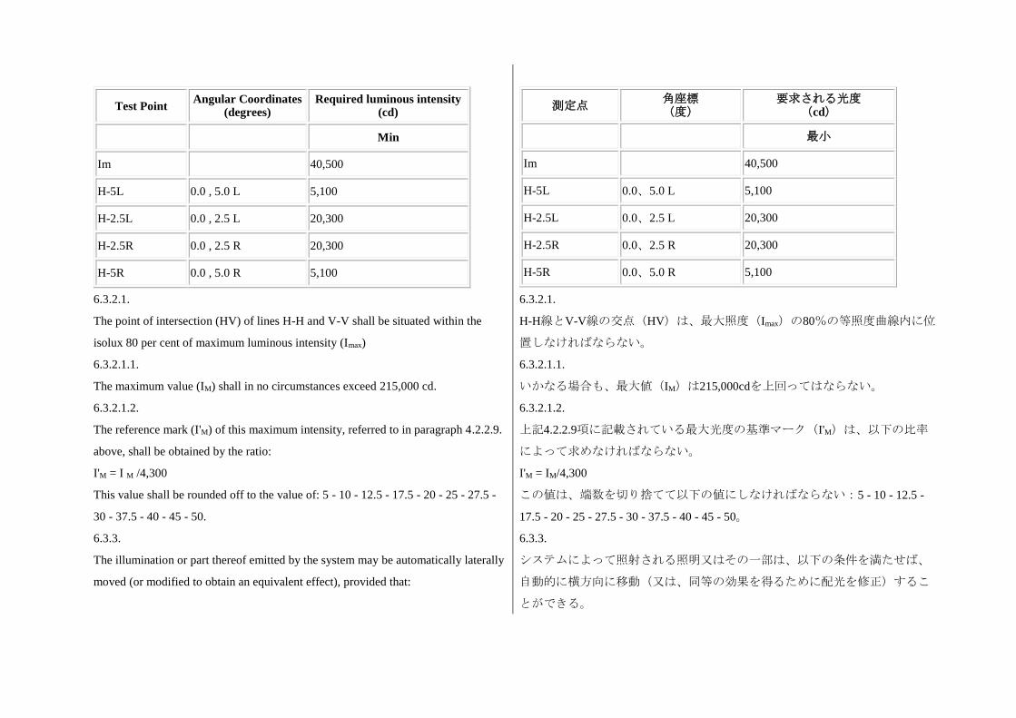
Test Point Angular Coordinates
(degrees) Required luminous intensity
(cd)
Min
Im 40,500
H-5L 0.0 , 5.0 L 5,100
H-2.5L 0.0 , 2.5 L 20,300
H-2.5R 0.0 , 2.5 R 20,300
H-5R 0.0 , 5.0 R 5,100
測定点 角座標 (度)
要求される光度 (cd)
最小
Im 40,500
H-5L 0.0、5.0 L 5,100
H-2.5L 0.0、2.5 L 20,300
H-2.5R 0.0、2.5 R 20,300
H-5R 0.0、5.0 R 5,100
6.3.2.1.
The point of intersection (HV) of lines H-H and V-V shall be situated within the
isolux 80 per cent of maximum luminous intensity (Imax)
6.3.2.1.1.
The maximum value (IM) shall in no circumstances exceed 215,000 cd.
6.3.2.1.2.
The reference mark (I'M) of this maximum intensity, referred to in paragraph 4.2.2.9.
above, shall be obtained by the ratio:
I'M = I M /4,300
This value shall be rounded off to the value of: 5 - 10 - 12.5 - 17.5 - 20 - 25 - 27.5 -
30 - 37.5 - 40 - 45 - 50.
6.3.2.1.
H-H線とV-V線の交点(HV)は、最大照度(Imax)の80%の等照度曲線内に位
置しなければならない。
6.3.2.1.1.
いかなる場合も、最大値(IM)は215,000cdを上回ってはならない。
6.3.2.1.2.
上記4.2.2.9項に記載されている最大光度の基準マーク(I'M)は、以下の比率
によって求めなければならない。
I'M = IM/4,300
この値は、端数を切り捨てて以下の値にしなければならない:5 - 10 - 12.5 -
17.5 - 20 - 25 - 27.5 - 30 - 37.5 - 40 - 45 - 50。
6.3.3.
The illumination or part thereof emitted by the system may be automatically laterally
moved (or modified to obtain an equivalent effect), provided that:
6.3.3.
システムによって照射される照明又はその一部は、以下の条件を満たせば、
自動的に横方向に移動(又は、同等の効果を得るために配光を修正)するこ
とができる。
6.3.3.1.
The system meets the requirements of the paragraphs 6.3.2.1.1. and 6.3.2.1.2. above
with each lighting unit measured according to the relevant procedure indicated in
Annex 9.
6.3.3.1.
附則9に記載されている関連手順に従って各灯火ユニットを測定したときに、
システムが上記6.3.2.1.1項及び6.3.2.1.2項の要件に適合すること。
6.3.4.
The system shall be so made that:
6.3.4.1. The lighting unit(s) of the right side and of the left side each provide at
least 16,200 cd at the point HV.
6.3.4.
システムは、以下の要件を満たすように製作されなければならない。
6.3.4.1. 右側および左側の灯火ユニットは、それぞれがHVポイントで少な
くとも16,200 cdを提供する。
6.3.5.
If the specified beam requirements are not met, a re-aiming of the beam position
within 0.5 degree up or down and/or 1 degree to the right or left, with respect to its
initial aiming is allowed; in the revised position all photometric requirements shall
be met. These provisions do not apply to lighting units as indicated under paragraph
6.3.1.1. of this Regulation.
6.3.5.
規定されたビームの要件が満たされない場合、当初の照準調整に対し、上下
いずれかに0.5°以内及び/又は左右いずれかに1°以内のビーム位置の再照準
調整を認める。再調整後の位置では、すべての配光要件が満たされなければ
ならない。これらの規定は、本規則の6.3.1.1項に記載されている灯火ユニッ
トには適用しない。
6.3.6.
In the case of adaptation of the driving-beam function the system shall meet the
requirements of the above paragraphs only when it is in the maximum condition of
activation.
6.3.6.
主走行ビーム機能の適応の場合は、システムは、最大の作動条件にある場合
に限り、上記の項の要件を満たさなければならない。
6.3.7.
During adaptation, the driving-beam function shall meet the requirements for all the
cases of Right-Hand and Left-Hand traffic specified in Part A of Table 7 in Annex 3
to this Regulation. These requirements shall be verified during the type approval
testing in conjunction with a signal generator to be provided by the applicant. This
signal generator shall reproduce the signals provided by the vehicle and cause the
adaptation of the driving-beam and in particular shall represent the settings so that
6.3.7.
適応中は、主走行ビーム機能は、本規則の附則3、表7のパートAに規定した
右側及び左側通行のすべての場合に関する要件を満たさなければならない。
これらの要件は、申請者が提供する信号発生器を用いた型式認可試験中に確
認しなければならない。当該信号発生器は、車両が提供する信号を再現して
主走行ビームの適応を生じさせるものとし、特に配光適合が確認できるよう
に設定を再現しなければならない。
the photometric compliance can be verified.
6.3.7.1.
If the driving-beam function meets the requirements in Part A of Table 7 in Annex 3
to this Regulation specified for line 1 to line 3 for oncoming and preceding vehicles
(symmetrical beam) the relevant information shall be noticed in the communication
document in Annex 1, paragraph 18.5.
6.3.7.2.
If the requirements of paragraph 6.3.7. above can be met for Right-Hand traffic or Left-Hand traffic only, the relevant information shall be reported in the communication document in Annex 1, paragraph 18.5.
6.3.7.1.
主走行ビーム機能が、対向車及び先行車に関する直線1から直線3について規
定した本規則の附則3表7のパートAの要件(対称ビーム)を満たす場合は、
該当する情報を附則1の18.5項の通知文書に記載しなければならない。
6.3.7.2.
右側通行又は左側通行に限り上記6.3.7項の要件を満たすことができる場合
は、該当する情報を附則1の18.5項の通知文書に記録しなければならない。
6.4.
Other provisions
In the case of a system or part(s) thereof with adjustable lighting units the
requirements of paragraphs 6.2. (passing beam), and 6.3. (driving beam) are
applicable for each mounting position indicated according to paragraph 2.1.3.
(adjustment range). For verification the following procedure shall be used:
6.4.
その他の規定
調節可能な灯火ユニットを用いたシステム又はその部品の場合、6.2項(すれ
違い用ビーム)及び6.3項(主走行ビーム)の要件を2.1.3項(調節範囲)に従
って示された各取り付け位置に適用する。検証のためには以下の手順を用い
なければならない。
6.4.1.
Each applied position is realized on the test goniometer with respect to a line joining
the center of reference and point HV on an aiming screen. The adjustable system or
part(s) thereof is then moved into such a position that the light pattern on the screen
corresponds to the relevant aiming prescriptions;
6.4.1.
適用される各位置は、照準調整スクリーン上で基準中心とHVのポイントを結
ぶ線を考慮し、回転台を用いて実現する。次に、調節可能なシステム又はそ
の部品を、スクリーン上の配光パターンが関連する照準調整の規定に対応す
るような位置に移動させる。
6.4.2.
With the system or part(s) thereof initially fixed according to paragraph 6.4.1., the
device or part(s) thereof must meet the relevant photometric requirements of
paragraphs 6.2. and 6.3.;
6.4.2.
システム又はその部品が6.4.1項に従って初期合わせされた状態で、装置又は
その部品は、6.2項及び6.3項の該当する配光要件に適合しなければならない。
6.4.3. 6.4.3.
Additional tests shall be made after the reflector/system or part(s) thereof has been
moved vertically +/-2 degrees or at least into the maximum position if less than 2
degrees, from its initial position by means of the system or part(s) thereof adjusting
device. Having re-aimed the system or part(s) thereof as a whole (by means of the
goniometer for example) in the corresponding opposite direction the light output in
the following directions shall be controlled and lie within the required limits:
6.4.3.1.
Passing beam: points HV and 75 R, or 50 R if applicable; driving beam: IM and point
HV (percentage of IM);
反射機構/システム又はその部品の調節装置によって当初の位置より垂直に
±2°の位置又は最大位置が2°を下回る場合には少なくとも最大位置に移動した
後で、追加試験を実施しなければならない。システム又はその部品の全体を
(例えば回転台を用いて)対応する逆方向に再照準調整した後、以下の方向
の光出力がコントロールされ、要求された限界値内に収めなければならな
い。
6.4.3.1.
すれ違い用ビーム:HV 及び 75R のポイント、又は該当する場合には 50R の
ポイント。主走行ビーム:IM及び HV のポイント(IMのパーセンテージ)
6.4.4.
If the applicant has indicated more than one mounting position, the procedure of
paragraphs 6.4.1. to 6.4.3. shall be repeated for all other positions;
6.4.4.
申請者が複数の取り付け位置を示している場合、6.4.1項から6.4.3項の手順を
他のすべての位置につき繰り返さなければならない。
6.4.5.
If the applicant has not asked for special mounting positions, the system or part(s)
thereof shall be aimed for measurements of paragraphs 6.2. (passing beam) and 6.3.
(driving beam) with the relevant adjusting device(s) of the system or part(s) thereof
in its mean position. The additional test of paragraph 6.4.3. shall be made with the
system or part(s) thereof, moved into its extreme positions (instead of +/-2 degrees)
by means of the relevant adjusting device(s).
6.4.5.
申請者が特別な取り付け位置を求めていない場合、システム又はその部品
は、関連する調節装置を中間位置に設定して6.2項(すれ違い用ビーム)及び
6.3項(主走行ビーム)の測定のための照準調整をしなければならない。6.4.3
項の追加試験は、関連する調節装置を用いて、システム又はその部品を(±2°
ではなく)調整可能な極限位置に移動して実施しなければならない。
6.4.6.
It shall be stated by means of a form conforming to the model in Annex 1 to this
Regulation, which lighting unit(s) provide a "cut-off" as defined in Annex 8 of this
Regulation, that projects into a zone extending from 6 degrees left to 4 degrees right
and upwards from a horizontal line positioned at 0.8 degree down.
6.4.6.
左に6°から右に4°まで及び0.8°下方に位置した水平線より上方に伸びた範囲に
投影される(本規則の附則8に定義されている)「カットオフ」をいずれの灯
火ユニットが提供するかを本規則の附則1のモデルに合致した書式で明示しな
ければならない。
6.4.7.
It shall be stated by means of a form conforming to the model in Annex 1 to this
Regulation, which class E passing beam mode(s), if any, comply with a "data set" of
Table 6 of Annex 3 of this Regulation.
6.4.7.
E 等級のすれ違い用ビームのいずれかの配光形態を有する場合に、本規則の附
則 3 の表 6 の「データセット」に適合するか否かを本規則の附則 1 のモデル
合致した書式で明示しなければならない。
7. Colour 7. 色
7.1.
The colour of the light emitted shall be white.
7.1.
発光色は白とする。
C. Further administrative provisions C. 補足的な行政規定
8. Modification of the system type and extension of approval 8. システムの型式の変更及び認可の拡大
8.1.
Every modification of the system type shall be notified to the administrative
department which approved the system type. The said department may then either:
8.1.1.
Consider that the modifications made are unlikely to have appreciable adverse
effects and that in any event the system still complies with the requirements; or
8.1.2.
Require a further test report from the Technical Service responsible for conducting
the tests.
8.1.
システムの型式を変更した場合、当該システムの型式を認可した行政官庁に
その都度届け出なければならない。届出を受けた行政官庁は、次のうちいず
れかの措置を取ることができる。
8.1.1.
実施された変更が著しい悪影響を与えるおそれがなく、且つ、いずれの場合
でもシステムが引き続き当該要件に適合すると判断する。又は、
8.1.2.
認可試験を担当する技術機関に試験報告書を改めて要求する。
8.2.
Confirmation or refusal of approval, specifying the alterations, shall be
communicated by the procedure specified in paragraph 4.1.4. above to the
8.2.
本規則を適用する協定締約国に対し、変更内容を明記した認可の承認又は拒
否を上記4.1.4項に規定された手順によって通知しなければならない。
Contracting Parties to the Agreement which apply this Regulation.
8.3.
The competent authority issuing the extension of approval shall assign a series
number to each communication form drawn up for such an extension and inform
thereof the other Parties to the 1958 Agreement applying this Regulation by means
of a communication form conforming to the model in Annex 1 to this Regulation.
8.3.
認可の拡大を付与する行政官庁は、認可の拡大のために作成した各通知書に
通し番号を割り振り、本規則の附則1のひな形に準拠する通知書により、本規
則を適用する1958年協定の他の締約国にこれを通知しなければならない。
9. Conformity of production
The conformity of production procedures shall comply with those set out in the
Agreement, Appendix 2 (E/ECE/324-E/ECE/TRANS/505/Rev.2) with the following
requirements:
9. 生産の適合性
生産の適合性手順は、以下に記載する要件と共に本規則の付録2(E/ECE/324-
E/ECE/TRANS/505/Rev.2)に規定された手順に適合しなければならない。
9.1.
A system approved under this Regulation shall be so manufactured as to conform to
the type approved by meeting the requirements set forth in paragraphs 6. and 7.
9.1.
本規則に基づき認可されたシステムは、6項及び7項に記載されている要件を
満たすことによって、認可された型式に適合するよう製造しなければならな
い。
9.2.
The minimum requirements for conformity of production control procedures set
fourth in Annex 5 to this Regulation shall be complied with.
9.2.
本規則の附則5に規定した生産の適合性管理手順に関する最小要件に適合しな
ければならない。
9.3.
The minimum requirements for sampling by an inspector set forth in Annex 7 to this
Regulation shall be complied with.
9.3.
本規則の附則7に規定した検査官による抜取検査に関する最小要件に適合しな
ければならない。
9.4.
The authority which has granted type approval may at any time verify the conformity
control methods applied in each production facility. The normal frequency of these
verifications shall be once every two years.
9.4.
型式の認可を付与した行政官庁は、各生産施設において用いられる生産の適
合性に関する管理方法を随時確認することができる。この確認の頻度は、通
常2年に1回とする。
9.5.
Systems or part(s) thereof with apparent defects are disregarded.
9.5.
明らかな瑕疵があるシステム又はその部品は、考慮の対象外とする。
9.6.
The reference mark is disregarded.
9.6.
基準マークは考慮の対象外とする。
10. Penalties for non-conformity of production 10. 生産の不適合に対する罰則
10.1.
The approval granted in respect of a type of system pursuant to this Regulation may
be withdrawn if the requirements are not complied with or if a system or part(s)
thereof bearing the approval mark does not conform to the type approved.
10.1.
本規則に準じたシステムの型式に関して付与された認可は、要件が満たされ
ない場合又は認可マークを貼付したシステム又はその部品が認可された型式
に合致しない場合に取り消すことができる。
10.2.
If a Contracting Party to the Agreement applying this Regulation withdraws an
approval it has previously granted, it shall forthwith so notify the other Contracting
Parties applying this Regulation by means of a communication form conforming to
the model in Annex 1 to this Regulation.
10.2.
本規則を適用する協定加盟国が以前に付与した認可を取り消す場合、当該国
は本規則を適用する他の協定締約国に対し、本規則の附則1のひな形に準拠す
る通知書を用いて速やかにその旨を通知しなければならない。
11. Production definitely discontinued 11. 生産中止
11.1.
If the holder of the approval completely ceases to manufacture a type of system
approved in accordance with this Regulation, he shall so inform the authority, which
granted the approval. Upon receiving the relevant communication, that authority
shall inform thereof the other Contracting Parties to the 1958 Agreement applying
this Regulation by means of a communication form conforming to the model in
Annex 1 to this Regulation.
11.1.
認可の保有者が本規則に従って認可されたシステムの型式の生産を全面的に
中止する場合、認可を付与した行政官庁にその旨を通知しなければならな
い。行政官庁は、該当する通知を受け取った後、本規則を適用する他の1958
年協定締約国に対し、本規則の附則1のひな形に準拠する通知書を用いてその
旨を通知しなければならない。
12. Names and addresses of Technical Services responsible for conducting
approval tests and of Administrative Departments
12. 認可試験を担当する技術機関と行政官庁の名称及び所在地
12.1.
The Contracting Parties to the 1958 Agreement applying this Regulation shall
communicate to the United Nations Secretariat the names and addresses of the
Technical Services responsible for conducting approval tests and of the
administrative departments which grant approval and to which forms certifying
approval or extension or refusal or withdrawal of approval, or production definitely
discontinued, issued in other countries, are to be sent.
12.1.
本規則を適用する1958年協定締約国は、認可試験を担当する技術機関の名称
及び所在地と、認可を付与し、且つ他国で交付された認可、認可の拡大、認
可の拒否、認可の取り消し又は生産中止を証明する書式の送付先となる行政
官庁の名称及び所在地を国連事務局に通知しなければならない。
13. Transitional provisions 13. 過渡規定
13.1.
From the date of entry into force of the 01 series of amendments to this Regulation,
no Contracting Party applying it shall refuse to grant approvals under this Regulation
as amended by the 01 series of amendments.
13.1.
本規則の第1改訂版の発効日より、本規則を適用する締約国は、第1改訂版に
より改訂された本規則に基づく認可の付与を拒否しないものとする。
13.2.
Until 60 months after the date of entry into force of the 01 series of amendments to
this Regulation with regard to the changes introduced by the 01 series of
amendments concerning the photometric testing procedures involving the use of the
spherical coordinate system and the specification of luminous intensity values, and in
order to allow the Technical Services to update their testing equipment, no
Contracting Party applying this Regulation shall refuse to grant approvals under this
Regulation as amended by the 01 series of amendments where existing testing
equipment is used with suitable conversion of the values, to the satisfaction of the
authority responsible for type approval.
13.2.
球面座標系の使用及び光度値の仕様を含む配光測定試験手順について第1改訂
版に導入された変更に関する本規則の第1改訂版の発効日から60ヶ月が経過す
るまで、並びに、技術機関が試験機器を更新することができるように、本規
則を適用する締約国は、値を適切に換算した上で既存の試験機器が使用さ
れ、これについて型式認可を担当する行政官庁が納得した場合には、第1改訂
版により改訂された本規則に基づく認可の付与を拒否しないものとする。
13.3.
As from 60 months after the date of entry into force of the 01 series of amendments,
Contracting Parties applying this Regulation shall grant approvals only if the system
meets the requirements of this Regulation as amended by the 01 series of
amendments.
13.3.
第1改訂版の発効日から60ヶ月が経過した後より、本規則を適用する協定締約
国は、システムが第1改訂版により改訂された本規則の要件を満たしている場
合に限り、認可を付与しなければならない。
13.4.
Existing approvals for systems already granted under this Regulation before the date
of entry into force of the 01 series of amendments shall remain valid indefinitely.
13.4.
第1改訂版の発効日より前に本規則に基づいてシステムに対して既に付与され
た既存の認可は、無期限に有効で有り続けなければならない。
13.5.
Contracting Parties applying this Regulation shall not refuse to grant extensions of
approvals to the preceding series to this Regulation
13.5.
本規則を適用する協定締約国は、本規則の先行改訂版に基づく認可の拡大を
付与することを拒否しないものとする。
Annex 1
Communication
(Maximum format: A4 (210 x 297 mm))
issued by: Name of administration:
......................................
......................................
......................................
1 Distinguishing number of the country which has granted/ extended/ refused/
附則1
通知
(最大A4判(210×297mm))
発行:行政官庁名
.......................................
.......................................
.......................................
1 認可の付与/認可の拡大/認可の拒否/認可の取り消しを行った国の識別
withdrawn approval (see the provisions of the Regulation concerning approval).
concerning2:
2 Strike out what does not apply.
APPROVAL GRANTED
APPROVAL EXTENDED
APPROVAL REFUSED
APPROVAL WITHDRAWN
PRODUCTION DEFINITELY DISCONTINUED
of a type of system pursuant to Regulation No. 123
Approval No.
Extension No.
番号(認可に関する規則の規定を参照。)
以下を記載する。2
2 該当しないものを抹消する。
協定規則第123号に基づく、準じたシステムの型式の
認可付与
認可拡大
認可拒否
認可取消
生産中止
認可番号:
拡大番号:
1. Trade name or mark of the system: 1. システムの商号又は商標:
2. Manufacturer's name for the type of system: 2. システムの型式に対する車両メーカー等の名称:
3. Manufacturer's name and address: 3. 車両メーカー等の名称及び所在地:
4. If applicable, name and address of manufacturer's representative: 4. 該当する場合には、車両メーカー等の代理人の名称及び所在地:
5. Submitted for approval on: 5. 認可申請日:
6. Technical Service responsible for conducting approval tests: 6. 認可試験を担当する技術機関:
7. Date of report issued by that service: 7. 上記の機関による試験成績書発行日:
8. Number of report issued by that service: 8. 上記の機関による試験成績書番号:
9. Brief description: 9. 簡潔な説明:
9.1.
Category as described by the relevant marking3
3 Indicate the appropriate marking as foreseen according to this Regulation for each
installation unit or assembly of installation units
9.1.
該当する表示によって記載された種類3
3 各取り付けユニット又は取り付けユニットのアッセンブリに対し、本規則
に従って予定される該当表示を記載する。
9.2. 9.2.
Number and category(ies) of replaceable light sources
9.2.1.
Number and specific identification code(s) of LED module(s) and for each LED
module a statement whether it is replaceable or not: yes/no2
2 Strike out what does not apply.
9.2.2.
Number and specific identification code(s) of electronic light source control gear(s),
if applicable
9.2.3.
Total objective luminous flux as described in paragraph 5.13 exceeds 2,000 lumen:
yes/no2
2 Strike out what does not apply.
交換式光源の数及び種類
9.2.1.
LEDモジュールの数及び特定識別コード、並びに各LEDモジュールが交換式
であるか否かについての記載:はい/いいえ2
2 該当しないものを抹消する。
9.2.2.
電子式光源制御装置の数及び特定識別コード(該当する場合)
9.2.3.
5.13項に規定した総目標光束値が2,000ルーメンを超えている:はい/いいえ2
2 該当しないものを抹消する。
9.3.
(a) Indications according to paragraph 6.4.6. of this Regulation (which lighting
unit(s) provide a "cut-off" as defined in Annex 8 of this Regulation, that projects into
a zone extending from 6 degrees left to 4 degrees right and upwards from a
horizontal line positioned at 0.8 degree down)
(b) The adjustment of the "cut-off" has been determined at 10 m / 25 m2.
2 Strike out what does not apply.
(c) The determination of the minimum sharpness of the "cut-off" has been carried out
at 10 m / 25 m2
2 Strike out what does not apply.
9.3.
(a) 本規則の6.4.6項による灯火ユニットの指示(左側に6°から右側に4°まで、
0.8°下方に位置した水平線より上方に伸びた範囲に投影される(本規則の附
則8の定義にされている)「カットオフ」をどの灯火ユニットが提供するか)
(b) 10m/25m2において「カットオフ」の調節をした。
2 該当しないものを抹消する。
(c) 10m/25m2において「カットオフ」の最小鮮明度を求めた。
2 該当しないものを抹消する。
9.4.
The vehicle(s) for which the system is intended as original equipment
9.4.
システムが初期装備として用いられることが目的とされた車両
9.5. 9.5.
Whether approval is sought for a system which is not intended to be included as part
of the approval of a vehicle type according to Regulation No. 48: yes/no2
2 Strike out what does not apply.
9.5.1.
If in the affirmative: information sufficient to identify the vehicle(s) for which the
system is intended
協定規則第48号に従って車両の型式認可の一部に含まれないシステムとして
認可を求めるか否か:はい/いいえ2
2 該当しないものを抹消する。
9.5.1.
「はい」と回答した場合:当該システムが対象とする車両を特定するために
十分な情報
9.6.
Indications according to paragraph 6.4.7. of this Regulation (which class E passing
beam mode(s), if any, comply with a "data set" of Table 6 of Annex 3 of this
Regulation)
9.6.
本規則の6.4.7項による配光形態の指示(E等級のすれ違い用ビームのいずれ
かの配光形態を有する場合に本規則の附則3の表6の「データセット」に適合
するか)
9.7.
Whether approval is sought for a system intended to be installed on vehicles only,
which provide means for a stabilization/limitation of the system's supply:
yes/no2
2 Strike out what does not apply.
9.7.
システムの給電の安定/制限のための手段を備える車両のみに取り付けられ
ることが目的とされたシステムに関する認可を求めているか否か:
はい/いいえ2
2 該当しないものを抹消する。
9.8.
The adjustment of the "cut-off" has been determined at 10 m / 25 m2.
2 Strike out what does not apply.
The determination of the minimum sharpness of the "cut-off" has been carried out at
10 m / 25 m2.
2 Strike out what does not apply.
9.8.
10m/25m2において「カットオフ」の調節をした。
2 該当しないものを抹消する。
10m/25m2において「カットオフ」の最小鮮明度を求めた。
2 該当しないものを抹消する。
10. Approval mark(s) position(s): 10. 認可マークの位置:
11. Reason(s) for extension of approval: 11. 認可の拡大の理由:
12.
Approval granted / extended / refused / withdrawn2
12.
認可の付与/拡大/拒否/取り消し2
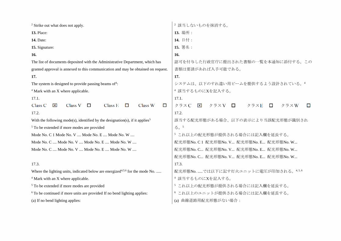
2 Strike out what does not apply. 2 該当しないものを抹消する。
13. Place: 13. 場所:
14. Date: 14. 日付:
15. Signature: 15. 署名:
16.
The list of documents deposited with the Administrative Department, which has
granted approval is annexed to this communication and may be obtained on request.
16.
認可を付与した行政官庁に提出された書類の一覧を本通知に添付する。この
書類は要請があれば入手可能である。
17.
The system is designed to provide passing beams of4:
4 Mark with an X where applicable.
17.
システムは、以下のすれ違い用ビームを提供するよう設計されている。4
4 該当するものにXを記入する。
17.1.
17.1.
17.2.
With the following mode(s), identified by the designation(s), if it applies5
5 To be extended if more modes are provided
Mode No. C 1 Mode No. V .... Mode No. E .... Mode No. W ....
Mode No. C .... Mode No. V .... Mode No. E .... Mode No. W ....
Mode No. C .... Mode No. V .... Mode No. E .... Mode No. W ....
17.2.
該当する配光形態がある場合、以下の表示により当該配光形態が識別され
る。5
5 これ以上の配光形態が提供される場合には記入欄を延長する。
配光形態No. C 1 配光形態No. V... 配光形態No. E... 配光形態No. W...
配光形態No. C... 配光形態No. V... 配光形態No. E... 配光形態No. W...
配光形態No. C... 配光形態No. V... 配光形態No. E... 配光形態No. W...
17.3.
Where the lighting units, indicated below are energized4,5,6 for the mode No. .....
4 Mark with an X where applicable.
5 To be extended if more modes are provided
6 To be continued if more units are provided If no bend lighting applies:
(a) If no bend lighting applies:
17.3.
配光形態No. .....では以下に記す灯火ユニットに電圧が印加される。4, 5, 6
4 該当するものにXを記入する。
5 これ以上の配光形態が提供される場合には記入欄を延長する。
6 これ以上のユニットが提供される場合には記入欄を延長する。
(a) 曲線道路用配光形態がない場合:
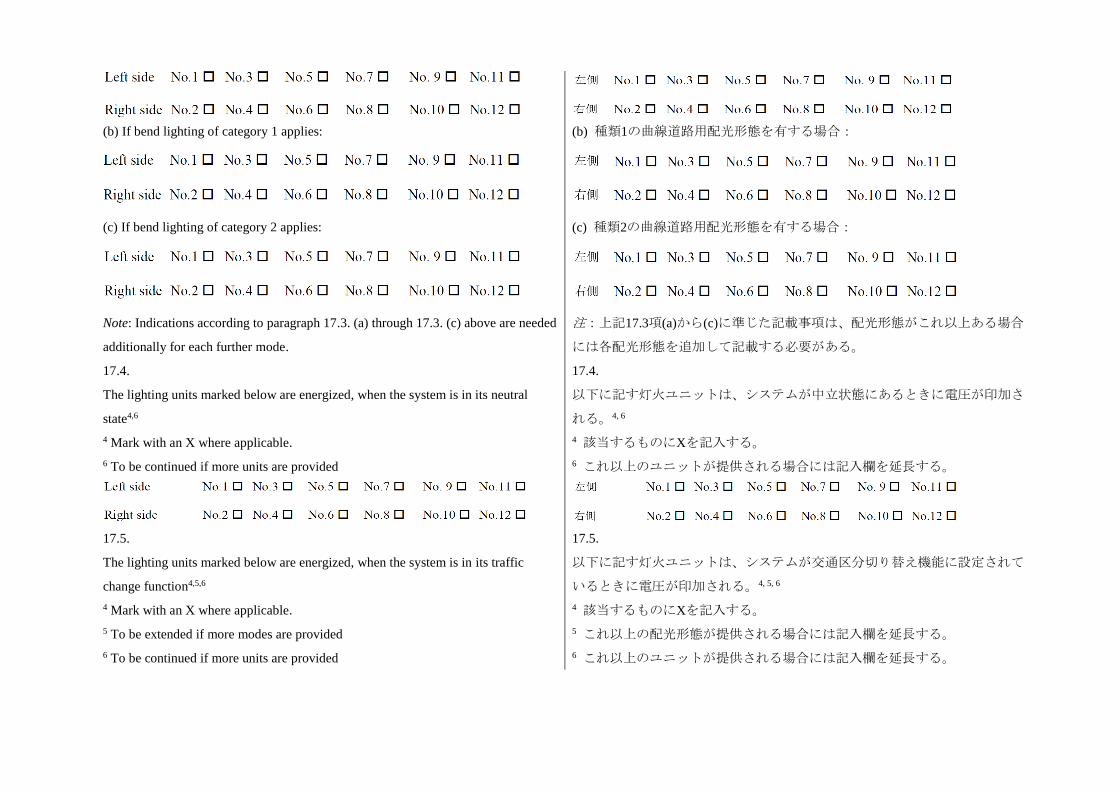
(b) If bend lighting of category 1 applies:
(c) If bend lighting of category 2 applies:
Note: Indications according to paragraph 17.3. (a) through 17.3. (c) above are needed
additionally for each further mode.
(b) 種類1の曲線道路用配光形態を有する場合:
(c) 種類2の曲線道路用配光形態を有する場合:
注:上記17.3項(a)から(c)に準じた記載事項は、配光形態がこれ以上ある場合
には各配光形態を追加して記載する必要がある。
17.4.
The lighting units marked below are energized, when the system is in its neutral
state4,6
4 Mark with an X where applicable.
6 To be continued if more units are provided
17.4.
以下に記す灯火ユニットは、システムが中立状態にあるときに電圧が印加さ
れる。4, 6
4 該当するものにXを記入する。
6 これ以上のユニットが提供される場合には記入欄を延長する。
17.5.
The lighting units marked below are energized, when the system is in its traffic
change function4,5,6
4 Mark with an X where applicable.
5 To be extended if more modes are provided
6 To be continued if more units are provided
17.5.
以下に記す灯火ユニットは、システムが交通区分切り替え機能に設定されて
いるときに電圧が印加される。4, 5, 6
4 該当するものにXを記入する。
5 これ以上の配光形態が提供される場合には記入欄を延長する。
6 これ以上のユニットが提供される場合には記入欄を延長する。
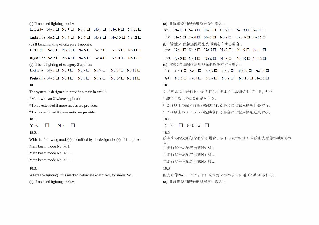
(a) If no bend lighting applies:
(b) If bend lighting of category 1 applies:
(c) If bend lighting of category 2 applies:
(a) 曲線道路用配光形態がない場合:
(b) 種類1の曲線道路用配光形態を有する場合:
(c) 種類2の曲線道路用配光形態を有する場合:
18.
The system is designed to provide a main beam4,5,6:
4 Mark with an X where applicable.
5 To be extended if more modes are provided
6 To be continued if more units are provided
18.
システムは主走行ビームを提供するように設計されている。4, 5, 6
4 該当するものにXを記入する。
5 これ以上の配光形態が提供される場合には記入欄を延長する。
6 これ以上のユニットが提供される場合には記入欄を延長する。
18.1.
18.1.
18.2.
With the following mode(s), identified by the designation(s), if it applies:
Main beam mode No. M 1
Main beam mode No. M ....
Main beam mode No. M ....
18.2.
該当する配光形態を有する場合、以下の表示により当該配光形態が識別される。
主走行ビーム配光形態No. M 1
主走行ビーム配光形態No. M ...
主走行ビーム配光形態No. M ...
18.3.
Where the lighting units marked below are energized, for mode No. ....
(a) If no bend lighting applies:
18.3.
配光形態No. .....では以下に記す灯火ユニットに電圧が印加される。
(a) 曲線道路用配光形態が無い場合:
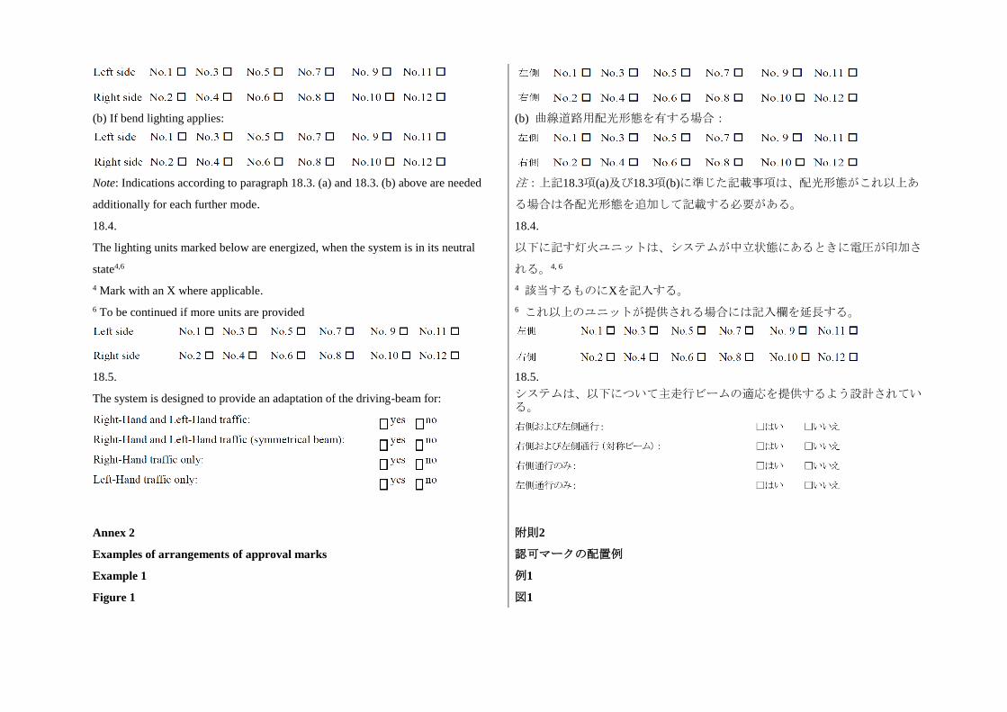
(b) If bend lighting applies:
Note: Indications according to paragraph 18.3. (a) and 18.3. (b) above are needed
additionally for each further mode.
(b) 曲線道路用配光形態を有する場合:
注:上記18.3項(a)及び18.3項(b)に準じた記載事項は、配光形態がこれ以上あ
る場合は各配光形態を追加して記載する必要がある。
18.4.
The lighting units marked below are energized, when the system is in its neutral
state4,6
4 Mark with an X where applicable.
6 To be continued if more units are provided
18.4.
以下に記す灯火ユニットは、システムが中立状態にあるときに電圧が印加さ
れる。4, 6
4 該当するものにXを記入する。
6 これ以上のユニットが提供される場合には記入欄を延長する。
18.5.
The system is designed to provide an adaptation of the driving-beam for:
18.5.
システムは、以下について主走行ビームの適応を提供するよう設計されている。
Annex 2
Examples of arrangements of approval marks
附則2
認可マークの配置例
Example 1 例1
Figure 1 図1
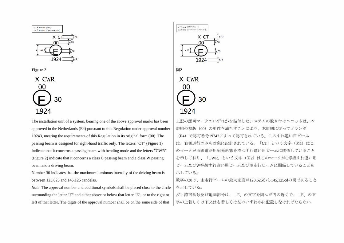
Figure 2
図2
The installation unit of a system, bearing one of the above approval marks has been
approved in the Netherlands (E4) pursuant to this Regulation under approval number
19243, meeting the requirements of this Regulation in its original form (00). The
passing beam is designed for right-hand traffic only. The letters "CT" (Figure 1)
indicate that it concerns a passing beam with bending mode and the letters "CWR"
(Figure 2) indicate that it concerns a class C passing beam and a class W passing
beam and a driving beam.
Number 30 indicates that the maximum luminous intensity of the driving beam is
between 123,625 and 145,125 candelas.
Note: The approval number and additional symbols shall be placed close to the circle
surrounding the letter "E" and either above or below that letter "E", or to the right or
left of that letter. The digits of the approval number shall be on the same side of that
上記の認可マークのいずれかを貼付したシステムの取り付けユニットは、本
規則の初版(00)の要件を満たすことにより、本規則に従ってオランダ
(E4)で認可番号19243によって認可されている。このすれ違い用ビーム
は、右側通行のみを対象に設計されている。「CT」という文字(図1)はこ
のマークが曲線道路用配光形態を持つすれ違い用ビームに関係していること
を示しており、「CWR」という文字(図2)はこのマークがC等級すれ違い用
ビーム及びW等級すれ違い用ビーム及び主走行ビームに関係していることを
示している。
数字の30は、主走行ビームの最大光度が123,625から145,125cdの間であること
を示している。
注:認可番号及び追加記号は、「E」の文字を囲んだ円の近くで、「E」の文
字の上若しくは下又は右若しくは左のいずれかに配置しなければならない。
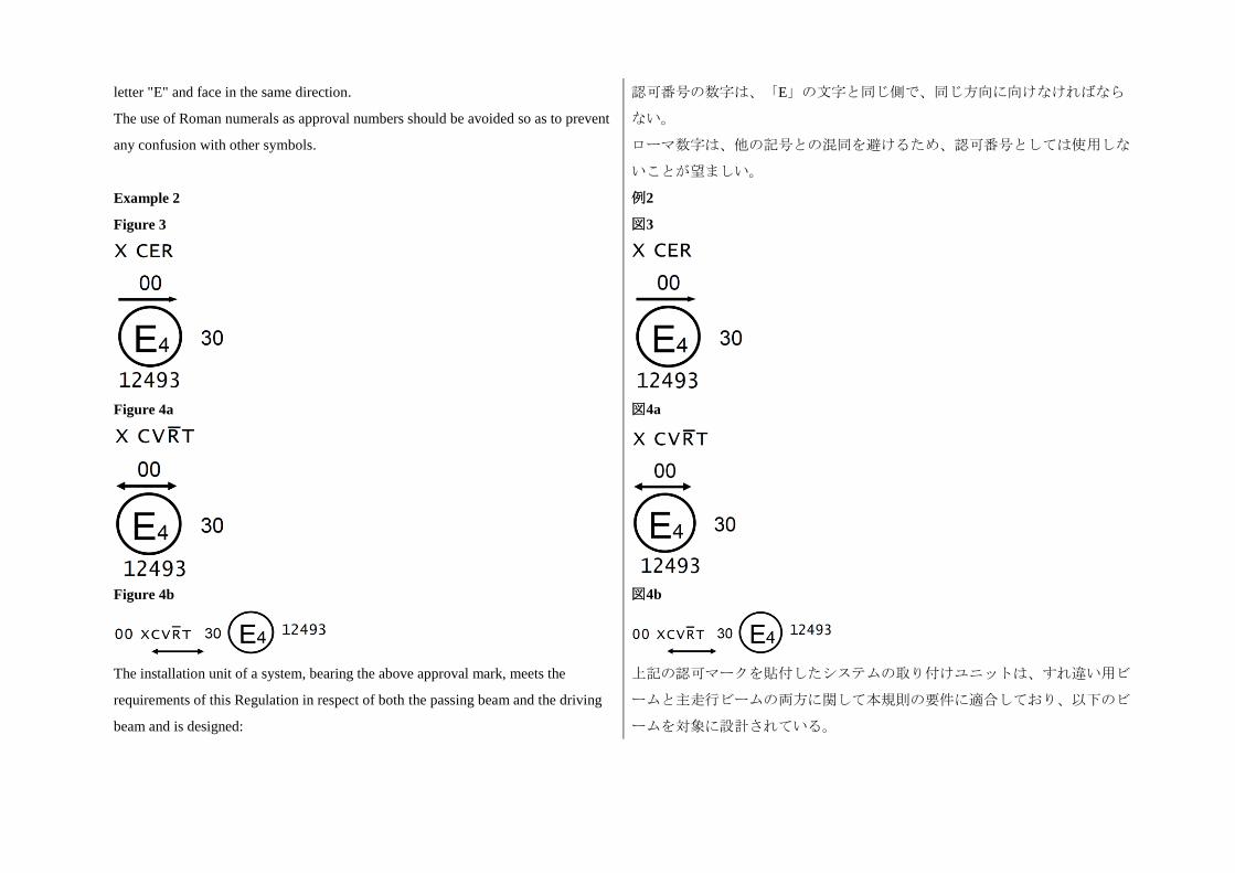
letter "E" and face in the same direction.
The use of Roman numerals as approval numbers should be avoided so as to prevent
any confusion with other symbols.
認可番号の数字は、「E」の文字と同じ側で、同じ方向に向けなければなら
ない。
ローマ数字は、他の記号との混同を避けるため、認可番号としては使用しな
いことが望ましい。
Example 2 例2
Figure 3
図3
Figure 4a
図4a
Figure 4b
図4b
The installation unit of a system, bearing the above approval mark, meets the
requirements of this Regulation in respect of both the passing beam and the driving
beam and is designed:
上記の認可マークを貼付したシステムの取り付けユニットは、すれ違い用ビ
ームと主走行ビームの両方に関して本規則の要件に適合しており、以下のビ
ームを対象に設計されている。
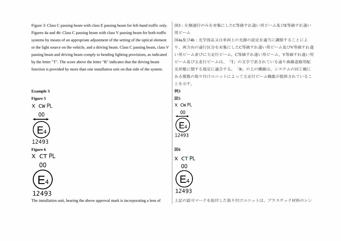
Figure 3: Class C passing beam with class E passing beam for left-hand traffic only.
Figures 4a and 4b: Class C passing beam with class V passing beam for both traffic
systems by means of an appropriate adjustment of the setting of the optical element
or the light source on the vehicle, and a driving beam. Class C passing beam, class V
passing beam and driving beam comply to bending lighting provisions, as indicated
by the letter "T". The score above the letter "R" indicates that the driving beam
function is provided by more than one installation unit on that side of the system.
図3:左側通行のみを対象にしたC等級すれ違い用ビーム及びE等級すれ違い
用ビーム
図4a及び4b:光学部品又は車両上の光源の設定を適当に調節することによ
り、両方向の通行区分を対象にしたC等級すれ違い用ビーム及びV等級すれ違
い用ビーム並びに主走行ビーム。C等級すれ違い用ビーム、V等級すれ違い用
ビーム及び主走行ビームは、「T」の文字で表されている通り曲線道路用配
光形態に関する規定に適合する。「R」の上の横線は、システムの同じ側に
ある複数の取り付けユニットによって主走行ビーム機能が提供されているこ
とを示す。
Example 3 例3
Figure 5
図5
Figure 6
図6
The installation unit, bearing the above approval mark is incorporating a lens of 上記の認可マークを貼付した取り付けユニットは、プラスチック材料のレン
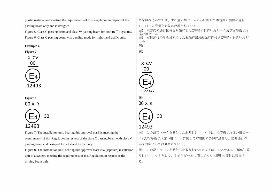
plastic material and meeting the requirements of this Regulation in respect of the
passing beam only and is designed:
Figure 5: Class C passing beam and class W passing beam for both traffic systems.
Figure 6: Class C passing beam with bending mode for right-hand traffic only.
ズを組み込んでおり、すれ違い用ビームのみに関して本規則の要件に適合
し、以下の照明を対象に設計されている。
図5:両方向の通行区分を対象にしたC等級すれ違い用ビーム及びW等級すれ違い用ビーム 図6:右側通行のみを対象にした曲線道路用配光形態付きC等級すれ違い用ビーム
Example 4 例4
Figure 7
図7
Figure 8
図8
Figure 7: The installation unit, bearing this approval mark is meeting the
requirements of this Regulation in respect of the class C passing beam with class V
passing beam and designed for left-hand traffic only.
Figure 8: The installation unit, bearing this approval mark is a (separate) installation
unit of a system, meeting the requirements of this Regulation in respect of the
driving beam only.
図7:この認可マークを貼付した取り付けユニットは、C等級すれ違い用ビー
ム及びV等級すれ違い用ビームに関して本規則の要件に適合し、左側通行の
みを対象にして設計されている。
図8:この認可マークを貼付した取り付けユニットは、システムの(単体)取
り付けユニットとして、主走行ビームに関してのみ本規則の要件に適合す
る。
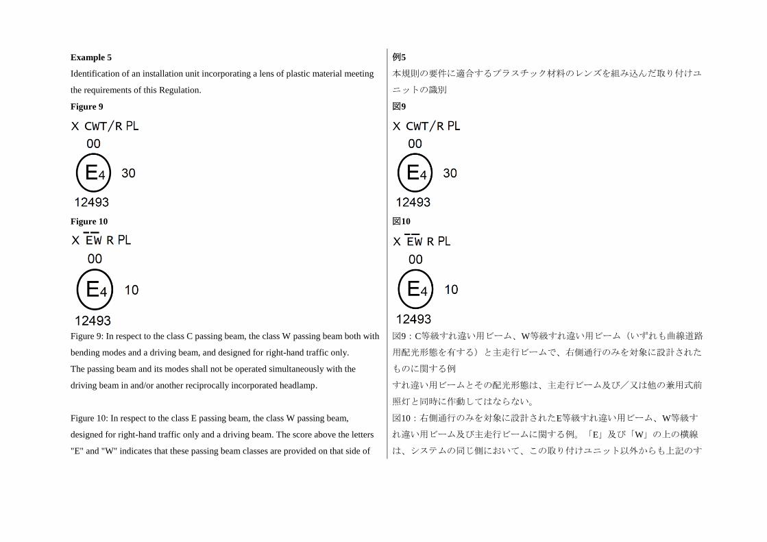
Example 5
Identification of an installation unit incorporating a lens of plastic material meeting
the requirements of this Regulation.
例5
本規則の要件に適合するプラスチック材料のレンズを組み込んだ取り付けユ
ニットの識別
Figure 9
図9
Figure 10
図10
Figure 9: In respect to the class C passing beam, the class W passing beam both with
bending modes and a driving beam, and designed for right-hand traffic only.
The passing beam and its modes shall not be operated simultaneously with the
driving beam in and/or another reciprocally incorporated headlamp.
図9:C等級すれ違い用ビーム、W等級すれ違い用ビーム(いずれも曲線道路
用配光形態を有する)と主走行ビームで、右側通行のみを対象に設計された
ものに関する例
すれ違い用ビームとその配光形態は、主走行ビーム及び/又は他の兼用式前
照灯と同時に作動してはならない。
Figure 10: In respect to the class E passing beam, the class W passing beam,
designed for right-hand traffic only and a driving beam. The score above the letters
"E" and "W" indicates that these passing beam classes are provided on that side of
図10:右側通行のみを対象に設計されたE等級すれ違い用ビーム、W等級す
れ違い用ビーム及び主走行ビームに関する例。「E」及び「W」の上の横線
は、システムの同じ側において、この取り付けユニット以外からも上記のす
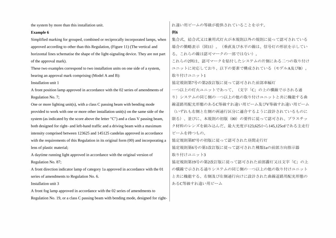
the system by more than this installation unit. れ違い用ビームの等級が提供されていることを示す。
Example 6
Simplified marking for grouped, combined or reciprocally incorporated lamps, when
approved according to other than this Regulation, (Figure 11) (The vertical and
horizontal lines schematise the shape of the light-signaling device. They are not part
of the approval mark).
These two examples correspond to two installation units on one side of a system,
bearing an approval mark comprising (Model A and B):
Installation unit 1
A front position lamp approved in accordance with the 02 series of amendments of
Regulation No. 7;
One or more lighting unit(s), with a class C passing beam with bending mode
provided to work with one or more other installation unit(s) on the same side of the
system (as indicated by the score above the letter "C") and a class V passing beam,
both designed for right- and left-hand traffic and a driving beam with a maximum
intensity comprised between 123625 and 145125 candelas approved in accordance
with the requirements of this Regulation in its original form (00) and incorporating a
lens of plastic material;
A daytime running light approved in accordance with the original version of
Regulation No. 87;
A front direction indicator lamp of category 1a approved in accordance with the 01
series of amendments to Regulation No. 6.
Installation unit 3
A front fog lamp approved in accordance with the 02 series of amendments to
Regulation No. 19, or a class C passing beam with bending mode, designed for right-
例6
集合式、結合式又は兼用式灯火が本規則以外の規則に従って認可されている
場合の簡略表示(図11)。(垂直及び水平の線は、信号灯の形状を示してい
る。これらの線は認可マークの一部ではない)。
これらの2例は、認可マークを貼付したシステムの片側にある二つの取り付け
ユニットに対応しており、以下の要素で構成されている(モデルA及びB)。
取り付けユニット1
協定規則第7号の第2改訂版に従って認可された前部車幅灯
一つ以上の灯火ユニットであって、(文字「C」の上の横線で示される通
り)システムの同じ側の一つ以上の他の取り付けユニットと共に機能する曲
線道路用配光形態のあるC等級すれ違い用ビーム及びV等級すれ違い用ビーム
(いずれも右側と左側の両通行区分に適合するように設計されているものに
限る)、並びに、本規則の初版(00)の要件に従って認可され、プラスチッ
ク材料のレンズを組み込んだ、最大光度が123,625から145,125cdである主走行
ビームを持つもの。
協定規則第87号の初版に従って認可された昼間走行灯
協定規則第6号の第1改訂版に従って認可された種類1aの前部方向指示器
取り付けユニット3
協定規則第19号の第2改訂版に従って認可された前部霧灯又は文字「C」の上
の横線で示される通りシステムの同じ側の一つ以上の他の取り付けユニット
と共に機能する、右側及び左側通行向けに設計された曲線道路用配光形態の
あるC等級すれ違い用ビーム
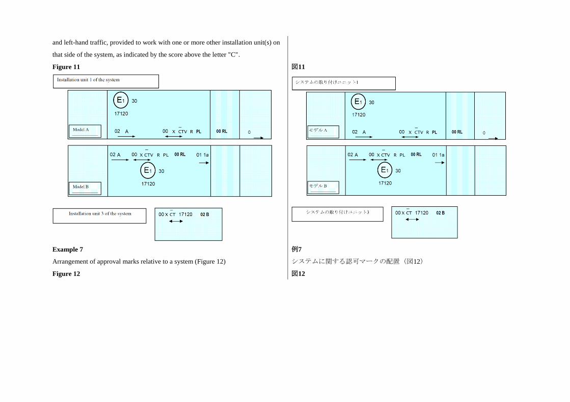
and left-hand traffic, provided to work with one or more other installation unit(s) on
that side of the system, as indicated by the score above the letter "C".
Figure 11
図11
Example 7
Arrangement of approval marks relative to a system (Figure 12)
例7
システムに関する認可マークの配置(図12)
Figure 12 図12
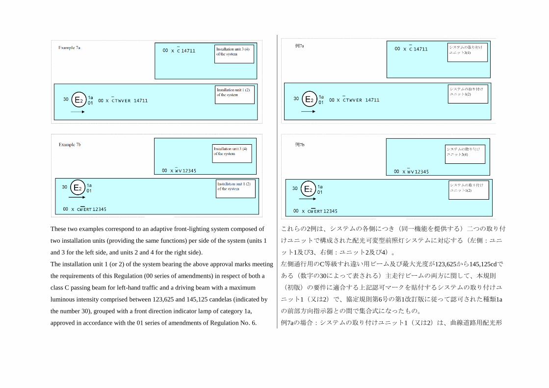
These two examples correspond to an adaptive front-lighting system composed of
two installation units (providing the same functions) per side of the system (units 1
and 3 for the left side, and units 2 and 4 for the right side).
The installation unit 1 (or 2) of the system bearing the above approval marks meeting
the requirements of this Regulation (00 series of amendments) in respect of both a
class C passing beam for left-hand traffic and a driving beam with a maximum
luminous intensity comprised between 123,625 and 145,125 candelas (indicated by
the number 30), grouped with a front direction indicator lamp of category 1a,
approved in accordance with the 01 series of amendments of Regulation No. 6.
これらの2例は、システムの各側につき(同一機能を提供する)二つの取り付
けユニットで構成された配光可変型前照灯システムに対応する(左側:ユニ
ット1及び3、右側:ユニット2及び4)。
左側通行用のC等級すれ違い用ビーム及び最大光度が123,625から145,125cdで
ある(数字の30によって表される)主走行ビームの両方に関して、本規則
(初版)の要件に適合する上記認可マークを貼付するシステムの取り付けユ
ニット1(又は2)で、協定規則第6号の第1改訂版に従って認可された種類1a
の前部方向指示器との間で集合式になったもの。
例7aの場合:システムの取り付けユニット1(又は2)は、曲線道路用配光形
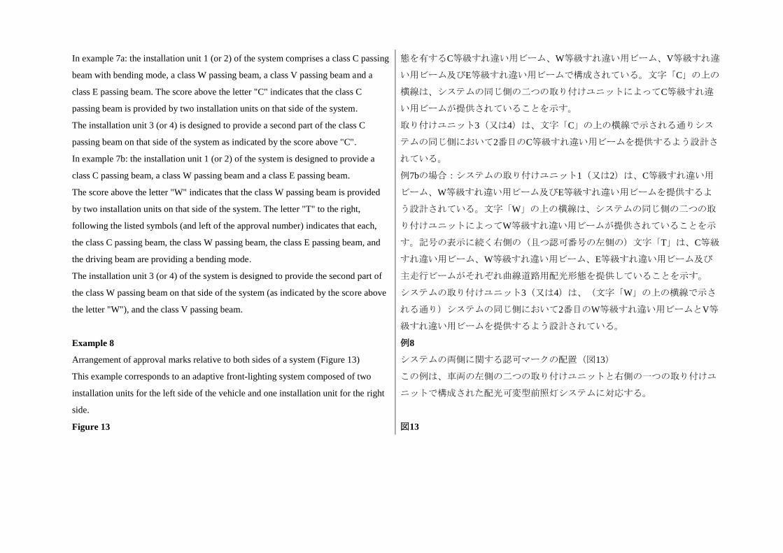
In example 7a: the installation unit 1 (or 2) of the system comprises a class C passing
beam with bending mode, a class W passing beam, a class V passing beam and a
class E passing beam. The score above the letter "C" indicates that the class C
passing beam is provided by two installation units on that side of the system.
The installation unit 3 (or 4) is designed to provide a second part of the class C
passing beam on that side of the system as indicated by the score above "C".
In example 7b: the installation unit 1 (or 2) of the system is designed to provide a
class C passing beam, a class W passing beam and a class E passing beam.
The score above the letter "W" indicates that the class W passing beam is provided
by two installation units on that side of the system. The letter "T" to the right,
following the listed symbols (and left of the approval number) indicates that each,
the class C passing beam, the class W passing beam, the class E passing beam, and
the driving beam are providing a bending mode.
The installation unit 3 (or 4) of the system is designed to provide the second part of
the class W passing beam on that side of the system (as indicated by the score above
the letter "W"), and the class V passing beam.
態を有するC等級すれ違い用ビーム、W等級すれ違い用ビーム、V等級すれ違
い用ビーム及びE等級すれ違い用ビームで構成されている。文字「C」の上の
横線は、システムの同じ側の二つの取り付けユニットによってC等級すれ違
い用ビームが提供されていることを示す。
取り付けユニット3(又は4)は、文字「C」の上の横線で示される通りシス
テムの同じ側において2番目のC等級すれ違い用ビームを提供するよう設計さ
れている。
例7bの場合:システムの取り付けユニット1(又は2)は、C等級すれ違い用
ビーム、W等級すれ違い用ビーム及びE等級すれ違い用ビームを提供するよ
う設計されている。文字「W」の上の横線は、システムの同じ側の二つの取
り付けユニットによってW等級すれ違い用ビームが提供されていることを示
す。記号の表示に続く右側の(且つ認可番号の左側の)文字「T」は、C等級
すれ違い用ビーム、W等級すれ違い用ビーム、E等級すれ違い用ビーム及び
主走行ビームがそれぞれ曲線道路用配光形態を提供していることを示す。
システムの取り付けユニット3(又は4)は、(文字「W」の上の横線で示さ
れる通り)システムの同じ側において2番目のW等級すれ違い用ビームとV等
級すれ違い用ビームを提供するよう設計されている。
Example 8
Arrangement of approval marks relative to both sides of a system (Figure 13)
This example corresponds to an adaptive front-lighting system composed of two
installation units for the left side of the vehicle and one installation unit for the right
side.
例8
システムの両側に関する認可マークの配置(図13)
この例は、車両の左側の二つの取り付けユニットと右側の一つの取り付けユ
ニットで構成された配光可変型前照灯システムに対応する。
Figure 13 図13
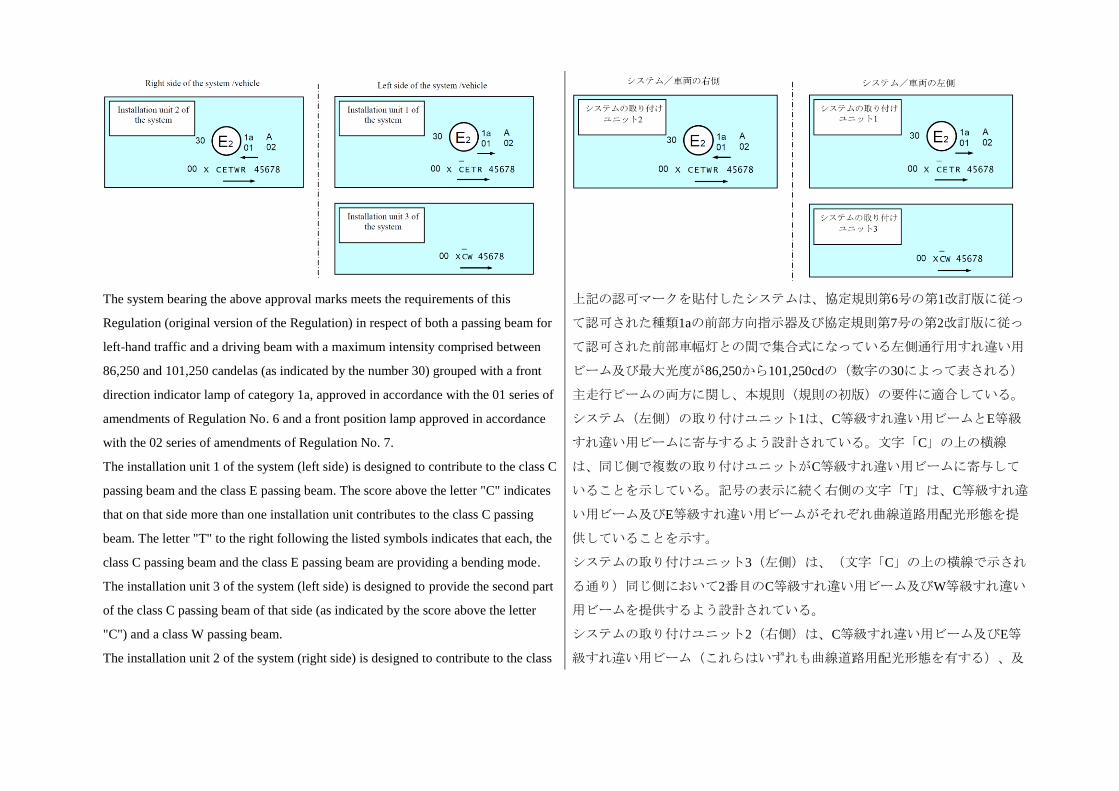
The system bearing the above approval marks meets the requirements of this
Regulation (original version of the Regulation) in respect of both a passing beam for
left-hand traffic and a driving beam with a maximum intensity comprised between
86,250 and 101,250 candelas (as indicated by the number 30) grouped with a front
direction indicator lamp of category 1a, approved in accordance with the 01 series of
amendments of Regulation No. 6 and a front position lamp approved in accordance
with the 02 series of amendments of Regulation No. 7.
The installation unit 1 of the system (left side) is designed to contribute to the class C
passing beam and the class E passing beam. The score above the letter "C" indicates
that on that side more than one installation unit contributes to the class C passing
beam. The letter "T" to the right following the listed symbols indicates that each, the
class C passing beam and the class E passing beam are providing a bending mode.
The installation unit 3 of the system (left side) is designed to provide the second part
of the class C passing beam of that side (as indicated by the score above the letter
"C") and a class W passing beam.
The installation unit 2 of the system (right side) is designed to contribute to the class
上記の認可マークを貼付したシステムは、協定規則第6号の第1改訂版に従っ
て認可された種類1aの前部方向指示器及び協定規則第7号の第2改訂版に従っ
て認可された前部車幅灯との間で集合式になっている左側通行用すれ違い用
ビーム及び最大光度が86,250から101,250cdの(数字の30によって表される)
主走行ビームの両方に関し、本規則(規則の初版)の要件に適合している。
システム(左側)の取り付けユニット1は、C等級すれ違い用ビームとE等級
すれ違い用ビームに寄与するよう設計されている。文字「C」の上の横線
は、同じ側で複数の取り付けユニットがC等級すれ違い用ビームに寄与して
いることを示している。記号の表示に続く右側の文字「T」は、C等級すれ違
い用ビーム及びE等級すれ違い用ビームがそれぞれ曲線道路用配光形態を提
供していることを示す。
システムの取り付けユニット3(左側)は、(文字「C」の上の横線で示され
る通り)同じ側において2番目のC等級すれ違い用ビーム及びW等級すれ違い
用ビームを提供するよう設計されている。
システムの取り付けユニット2(右側)は、C等級すれ違い用ビーム及びE等
級すれ違い用ビーム(これらはいずれも曲線道路用配光形態を有する)、及
C passing beam, a class E passing beam, both with bending mode and a class W
passing beam.
Note: In the above examples Nos. 6, 7 and the different installation units of the
system shall bear the same approval number.
びW等級すれ違い用ビームに寄与するよう設計されている。
注:上記の6、7及び8の例では、システムの各取り付けユニットに同一の認可
番号を貼付しなければならない。
Figure 14: LED modules
The LED module bearing the light source module identification code shown above
has been approved together with an AFS initially approved in Italy (E3) under
approval number 17325.
図14:LEDモジュール
上記の光源モジュールの識別コードを貼付したLEDモジュールは、イタリア
(E3)で認可番号17325によって最初に認可を受けたAFSとともに認可された
ものである。
Annex 3
Passing beam photometric requirements*
* Note: measurement procedure prescribed in Annex 9 to this Regulation.
For the purpose of this annex:
"above it" means vertically above, only;
"below it" means vertically below, only.
Angular positions are expressed in deg up (U) or down (D) from H-H respectively
right (R) or left (L) from V-V.
附則3
すれ違い用ビームの配光要件*
*注:本規則の附則9に規定されている測定手順
本附則では:
「その上」とは、垂直方向の上のみをいう。
「その下」とは、垂直方向の下のみをいう。
角度位置は、それぞれH-Hから上方向(U)若しくは下方向(D)、V-Vから
右方向(R)若しくは左方向(L)の角度を用いて表記する。
Figure 1: Angular positions of passing beam photometric requirements
(indicated for right-hand traffic)
図1:すれ違い用ビームの配光要件の角度位置(下記は右側通行を対象に表
示)
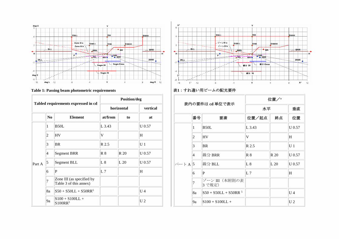
Table 1: Passing beam photometric requirements
Tabled requirements expressed in cd Position/deg
horizontal vertical
No Element at/from to at
Part A
1 B50L L 3.43 U 0.57
2 HV V H
3 BR R 2.5 U 1
4 Segment BRR R 8 R 20 U 0.57
5 Segment BLL L 8 L 20 U 0.57
6 P L 7 H
7 Zone III (as specified by Table 3 of this annex)
8a S50 + S50LL + S50RR5 U 4
9a S100 + S100LL + S100RR5
U 2
表1:すれ違い用ビームの配光要件
表内の要件は cd 単位で表示
位置/°
水平 垂直
番号 要素 位置/起点 終点 位置
パート A
1 B50L L 3.43 U 0.57
2 HV V H
3 BR R 2.5 U 1
4 線分 BRR R 8 R 20 U 0.57
5 線分 BLL L 8 L 20 U 0.57
6 P L 7 H
7 ゾーン III(本附則の表3 で規定)
8a S50 + S50LL + S50RR 5 U 4
9a S100 + S100LL + U 2
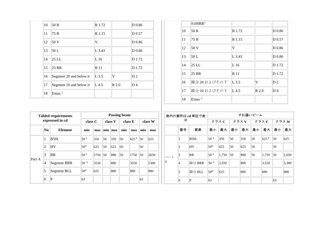
10 50 R R 1.72 D 0.86
11 75 R R 1.15 D 0.57
12 50 V V D 0.86
13 50 L L 3.43 D 0.86
14 25 LL L 16 D 1.72
15 25 RR R 11 D 1.72
16 Segment 20 and below it L 3.5 V D 2
17 Segment 10 and below it L 4.5 R 2.0 D 4
18 Emax 3
S100RR5
10 50 R R 1.72 D 0.86
11 75 R R 1.15 D 0.57
12 50 V V D 0.86
13 50 L L 3.43 D 0.86
14 25 LL L 16 D 1.72
15 25 RR R 11 D 1.72
16 線分 20 およびその下 L 3.5 V D 2
17 線分 10 およびその下 L 4.5 R 2.0 D 4
18 Emax 3
Tabled requirements
expressed in cd
Passing beam
class C class V class E class W
No Element min max min max min max min max
Part A
1 B50L 50 4 350 50 350 50 625 8 50 625
2 HV 504/ 625 50 625 50 50
3 BR 50 4 1750 50 880 50 1750 50 2650
4 Segment BRR 50 /4 3550 880 3550 5300
5 Segment BLL 504/ 625 880 880 880
6 P 63 63
表内の要件は cd 単位で表示
すれ違いビーム
クラス C クラス V クラス E クラス W
番号 要素 最小 最大 最小 最大 最小 最大 最小 最大
パート
A
1 B50L 50 4 350 50 350 50 625 8 50 625
2 HV 504/ 625 50 625 50 50
3 BR 50 4 1,750 50 880 50 1,750 50 2,650
4 線分 BRR 50 /4 3,550 880 3,550 5,300
5 線分 BLL 504/ 625 880 880 880
6 P 63 63
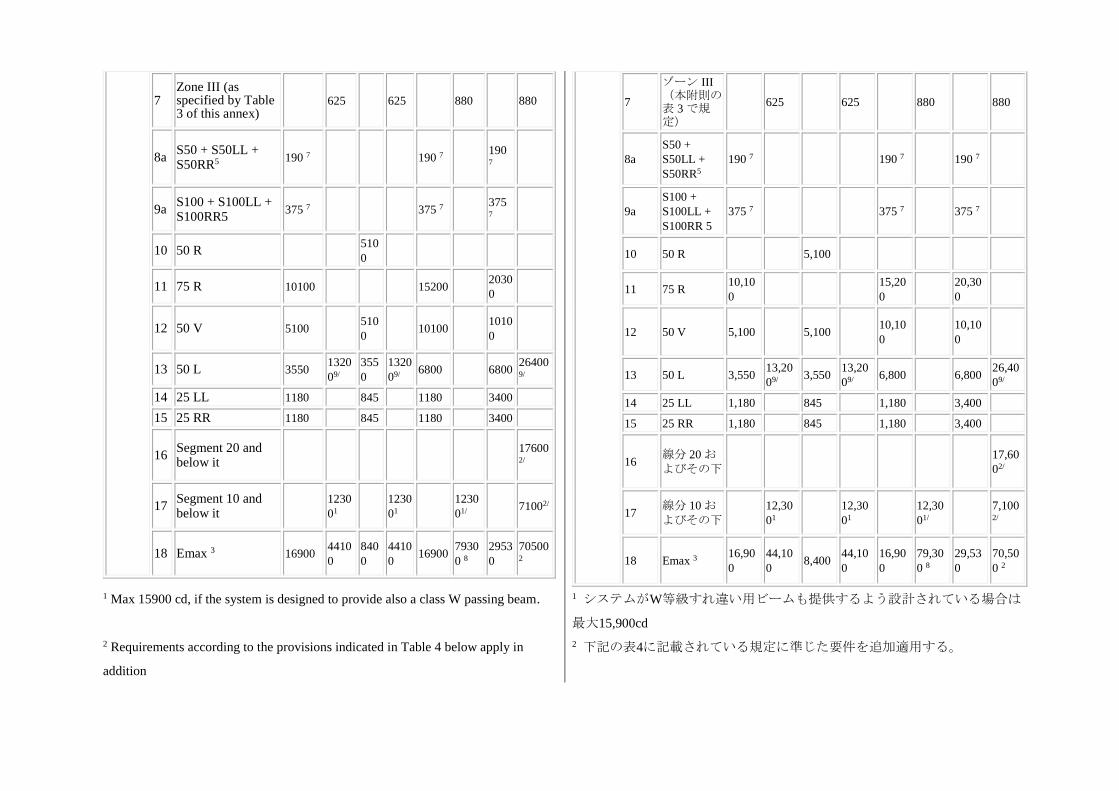
7 Zone III (as specified by Table 3 of this annex)
625 625 880 880
8a S50 + S50LL + S50RR5
190 7 190 7 190 7
9a S100 + S100LL + S100RR5
375 7 375 7 375 7
10 50 R 510
0
11 75 R 10100 15200 2030
0
12 50 V 5100 510
0 10100
1010
0
13 50 L 3550 1320
09/
355
0
1320
09/ 6800 6800
264009/
14 25 LL 1180 845 1180 3400
15 25 RR 1180 845 1180 3400
16 Segment 20 and below it
176002/
17 Segment 10 and below it
1230
01
1230
01
1230
01/ 71002/
18 Emax 3 16900 4410
0
840
0
4410
0 16900
7930
0 8
2953
0
70500 2
7
ゾーン III(本附則の表 3 で規定)
625 625 880 880
8a
S50 +
S50LL +
S50RR5
190 7 190 7 190 7
9a
S100 +
S100LL +
S100RR 5
375 7 375 7 375 7
10 50 R 5,100
11 75 R 10,10
0
15,20
0
20,30
0
12 50 V 5,100 5,100 10,10
0
10,10
0
13 50 L 3,550 13,20
09/ 3,550
13,20
09/ 6,800 6,800
26,40
09/
14 25 LL 1,180 845 1,180 3,400
15 25 RR 1,180 845 1,180 3,400
16 線分 20 およびその下
17,60
02/
17 線分 10 およびその下
12,30
01
12,30
01
12,30
01/
7,1002/
18 Emax 3 16,90
0
44,10
0 8,400
44,10
0
16,90
0
79,30
0 8
29,53
0
70,50
0 2
1 Max 15900 cd, if the system is designed to provide also a class W passing beam.
2 Requirements according to the provisions indicated in Table 4 below apply in
addition
1 システムがW等級すれ違い用ビームも提供するよう設計されている場合は
最大15,900cd
2 下記の表4に記載されている規定に準じた要件を追加適用する。
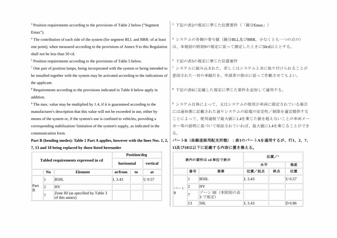
3 Position requirements according to the provisions of Table 2 below ("Segment
Emax").
4 The contribution of each side of the system (for segment BLL and BRR: of at least
one point), when measured according to the provisions of Annex 9 to this Regulation
shall not be less than 50 cd.
5 Position requirements according to the provisions of Table 5 below.
7 One pair of position lamps, being incorporated with the system or being intended to
be installed together with the system may be activated according to the indications of
the applicant.
8 Requirements according to the provisions indicated in Table 6 below apply in
addition.
9 The max. value may be multiplied by 1.4, if it is guaranteed according to the
manufacturer's description that this value will not be exceeded in use, either by
means of the system or, if the system's use is confined to vehicles, providing a
corresponding stabilization/ limitation of the system's supply, as indicated in the
communication form.
3 下記の表2の規定に準じた位置要件(「線分Emax」)
4 システムの各側の寄与値(線分BLL及びBRR。少なくとも一つの点の)
は、本規則の附則9の規定に従って測定したときに50cd以上とする。
5 下記の表5の規定に準じた位置要件
7 システムに組み込まれた、若しくはシステムと共に取り付けられることが
意図された一対の車幅灯を、申請者の指示に従って作動させてもよい。
8 下記の表6に記載した規定に準じた要件を追加して適用する。
9 システム自体によって、又はシステムの使用が車両に限定されている場合
には通知書に記載された通りシステムの給電の安定性/制限を適宜提供する
ことによって、使用過程で最大値に1.4を乗じた値を超えないことが車両メー
カー等の説明に基づいて保証されていれば、最大値に1.4を乗じることができ
る。
Part B (bending modes): Table 1 Part A applies, however with the lines Nos. 1, 2,
7, 13 and 18 being replaced by those listed hereunder
パートB(曲線道路用配光形態):表1のパートAを適用するが、行1、2、7、
13及び18は以下に記載する内容に置き換える。
Tabled requirements expressed in cd
Position/deg
horizontal vertical
No Element at/from to at
Part B
1 B50L L 3.43 U 0.57
2 HV
7 Zone III (as specified by Table 3 of this annex)
表内の要件は cd 単位で表示 位置/°
水平 垂直
番号 要素 位置/起点 終点 位置
パートB
1 B50L L 3.43 U 0.57
2 HV
7 ゾーン III(本附則の表3 で規定)
13 50L L 3.43 D 0.86
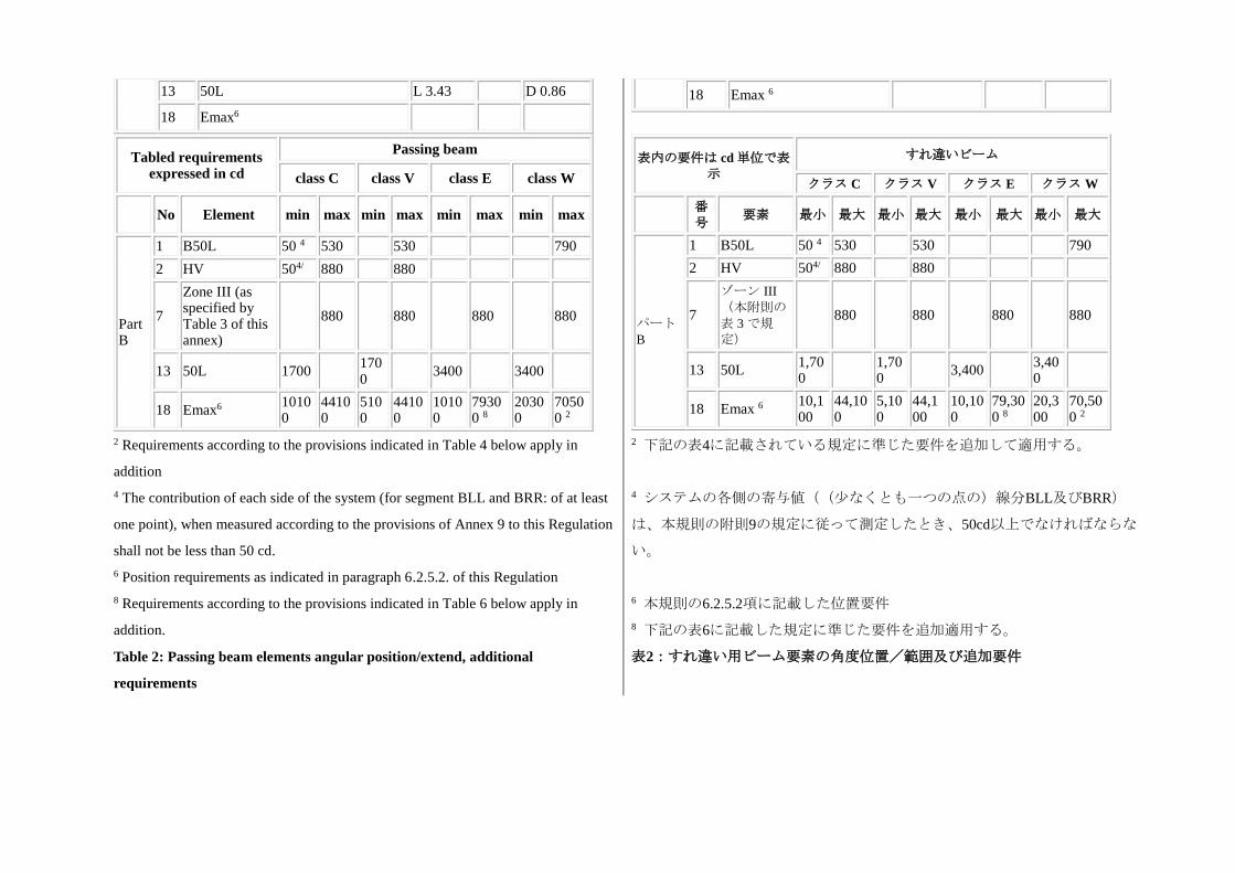
13 50L L 3.43 D 0.86
18 Emax6
18 Emax 6
Tabled requirements expressed in cd
Passing beam
class C class V class E class W
No Element min max min max min max min max
Part B
1 B50L 50 4 530 530 790
2 HV 504/ 880 880
7
Zone III (as specified by Table 3 of this annex)
880 880 880 880
13 50L 1700 1700
3400 3400
18 Emax6 10100
44100
5100
44100
10100
79300 8
20300
70500 2
表内の要件は cd 単位で表示
すれ違いビーム
クラス C クラス V クラス E クラス W
番号
要素 最小 最大 最小 最大 最小 最大 最小 最大
パートB
1 B50L 50 4 530 530 790
2 HV 504/ 880 880
7
ゾーン III
(本附則の表 3 で規定)
880 880 880 880
13 50L 1,700
1,700
3,400 3,400
18 Emax 6 10,100
44,100
5,100
44,100
10,100
79,300 8
20,300
70,500 2
2 Requirements according to the provisions indicated in Table 4 below apply in
addition
4 The contribution of each side of the system (for segment BLL and BRR: of at least
one point), when measured according to the provisions of Annex 9 to this Regulation
shall not be less than 50 cd.
6 Position requirements as indicated in paragraph 6.2.5.2. of this Regulation
8 Requirements according to the provisions indicated in Table 6 below apply in
addition.
2 下記の表4に記載されている規定に準じた要件を追加して適用する。
4 システムの各側の寄与値((少なくとも一つの点の)線分BLL及びBRR)
は、本規則の附則9の規定に従って測定したとき、50cd以上でなければならな
い。
6 本規則の6.2.5.2項に記載した位置要件
8 下記の表6に記載した規定に準じた要件を追加適用する。
Table 2: Passing beam elements angular position/extend, additional
requirements
表2:すれ違い用ビーム要素の角度位置/範囲及び追加要件
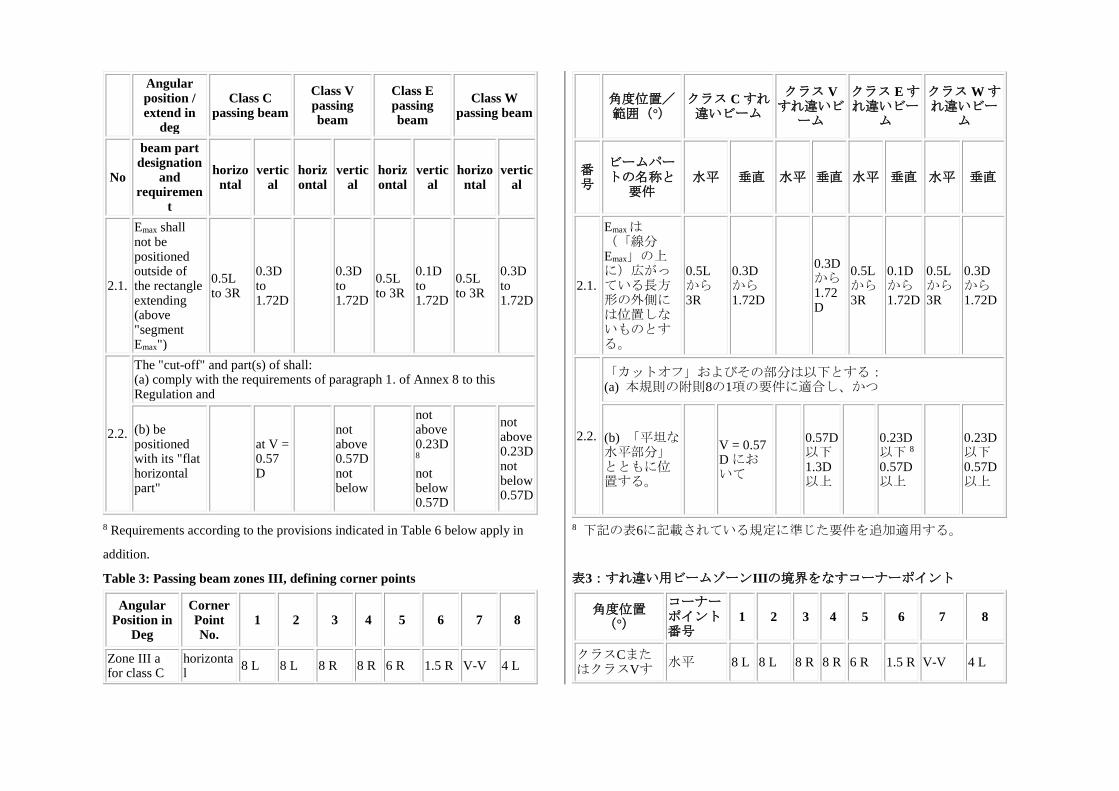
Angular position / extend in
deg
Class C passing beam
Class V passing beam
Class E passing beam
Class W passing beam
No
beam part designation
and requiremen
t
horizontal
vertical
horizontal
vertical
horizontal
vertical
horizontal
vertical
2.1.
Emax shall not be positioned outside of the rectangle extending (above "segment Emax")
0.5L to 3R
0.3D to 1.72D
0.3D to 1.72D
0.5L to 3R
0.1D to 1.72D
0.5L to 3R
0.3D to 1.72D
2.2.
The "cut-off" and part(s) of shall: (a) comply with the requirements of paragraph 1. of Annex 8 to this Regulation and
(b) be positioned with its "flat horizontal part"
at V = 0.57 D
not above 0.57D not below
not above 0.23D8 not below 0.57D
not above 0.23D not below 0.57D
角度位置/範囲(°)
クラス C すれ違いビーム
クラス Vすれ違いビ
ーム
クラス E すれ違いビー
ム
クラス W すれ違いビー
ム
番号
ビームパートの名称と
要件 水平 垂直 水平 垂直 水平 垂直 水平 垂直
2.1.
Emaxは(「線分Emax」の上に)広がっている長方形の外側には位置しないものとする。
0.5L から3R
0.3D から1.72D
0.3D から1.72D
0.5L から3R
0.1D から1.72D
0.5L から3R
0.3D から1.72D
2.2.
「カットオフ」およびその部分は以下とする: (a) 本規則の附則8の1項の要件に適合し、かつ
(b) 「平坦な水平部分」とともに位置する。
V = 0.57 D において
0.57D以下 1.3D以上
0.23D 以下 8 0.57D以上
0.23D以下 0.57D以上
8 Requirements according to the provisions indicated in Table 6 below apply in
addition.
8 下記の表6に記載されている規定に準じた要件を追加適用する。
Table 3: Passing beam zones III, defining corner points
Angular Position in
Deg
Corner Point No.
1 2 3 4 5 6 7 8
Zone III a for class C
horizontal
8 L 8 L 8 R 8 R 6 R 1.5 R V-V 4 L
表3:すれ違い用ビームゾーンIIIの境界をなすコーナーポイント
角度位置(°)
コーナーポイント番号
1 2 3 4 5 6 7 8
クラスCまたはクラスVす
水平 8 L 8 L 8 R 8 R 6 R 1.5 R V-V 4 L
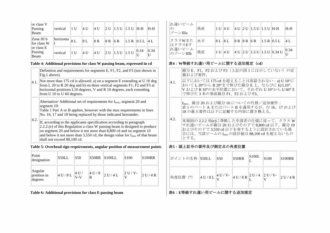
or class V Passing Beam
vertical 1 U 4 U 4 U 2 U 1.5 U 1.5 U H-H H-H
Zone III b for class W or class E Passing Beam
horizontal
8 L 8 L 8 R 8 R 6 R 1.5 R 0.5 L 4 L
vertical 1 U 4 U 4 U 2 U 1.5 U 1.5 U 0.34 U
0.34 U
れ違いビームの ゾーンIIIa
垂直 1 U 4 U 4 U 2 U 1.5 U 1.5 U H-H H-H
クラスWまたはクラスEすれ違いビームのゾーンIIIb
水平 8 L 8 L 8 R 8 R 6 R 1.5 R 0.5 L 4 L
垂直 1 U 4 U 4 U 2 U 1.5 U 1.5 U 0.34 U 0.34 U
Table 4: Additional provisions for class W passing beam, expressed in cd
4.1.
Definition and requirements for segments E, F1, F2, and F3 (not shown in Fig.1 above).
Not more than 175 cd is allowed: a) on a segment E extending at U 10 deg from L 20 to R 20 deg and b) on three vertical segments F1, F2 and F3 at horizontal positions L10 degrees, V and R 10 degrees, each extending from U 10 to U 60 degrees.
4.2.
Alternative/ Additional set of requirements for Imax, segment 20 and segment 10: Table 1 Part A or B applies, however with the max requirements in lines No. 16, 17 and 18 being replaced by those indicated hereunder.
If, according to the applicants specification according to paragraph 2.2.2.(e) of this Regulation a class W passing beam is designed to produce on segment 20 and below it not more than 8,800 cd and on segment 10 and below it not more than 3,550 cd, the design value for Imax of that beam shall not exceed 88,100 cd.
表4:W等級すれ違い用ビームに関する追加規定(cd)
4.1.
線分 E、F1、F2 および F3(上記の図 1 には示していない)の定義および要件。
以下においては 175 cd を超えることは容認されない:a) U 10°において L 20°から R 20°まで伸びた線分 E 上、ならびに b) L10°、V および R 10°の水平位置において、それぞれ U 10°から U 60°まで伸びた 3 本の垂直線分 F1、F2 および F3。
4.2.
Imax、線分 20 および線分 10 についての代替/追加要件: 表 1 のパート A またはパート B を適用するが、行 16、17 および18 の最大要件は以下に記載する内容に置き換える。
本規則の 2.2.2 項(e)に準拠した申請者の仕様に従って、クラス Wすれ違いビームが線分 20 およびその下で 8,800 cd 以下、線分 10およびその下で 3,550 cd 以下を発するように設計されている場合には、当該ビームの Imaxの設計値は 88,100 cd を超えないものとする。
Table 5: Overhead sign requirements, angular position of measurement points
Point designation
S50LL S50 S50RR S100LL S100 S100RR
Angular position in degrees
4 U / 8 L 4 U / V-V
4 U / 8 R
2 U / 4 L 2 U / V-V
2 U / 4 R
表5:頭上記号の要件及び測定点の角度位置
ポイントの名称 S50LL S50 S50RR S100LL
S100 S100RR
角度位置(°) 4 U / 8 L 4 U / V-V
4 U / 8 R 2 U / 4 L
2 U / V-V
2 U / 4 R
Table 6: Additional provisions for class E passing beam 表6:E等級すれ違い用ビームに関する追加規定
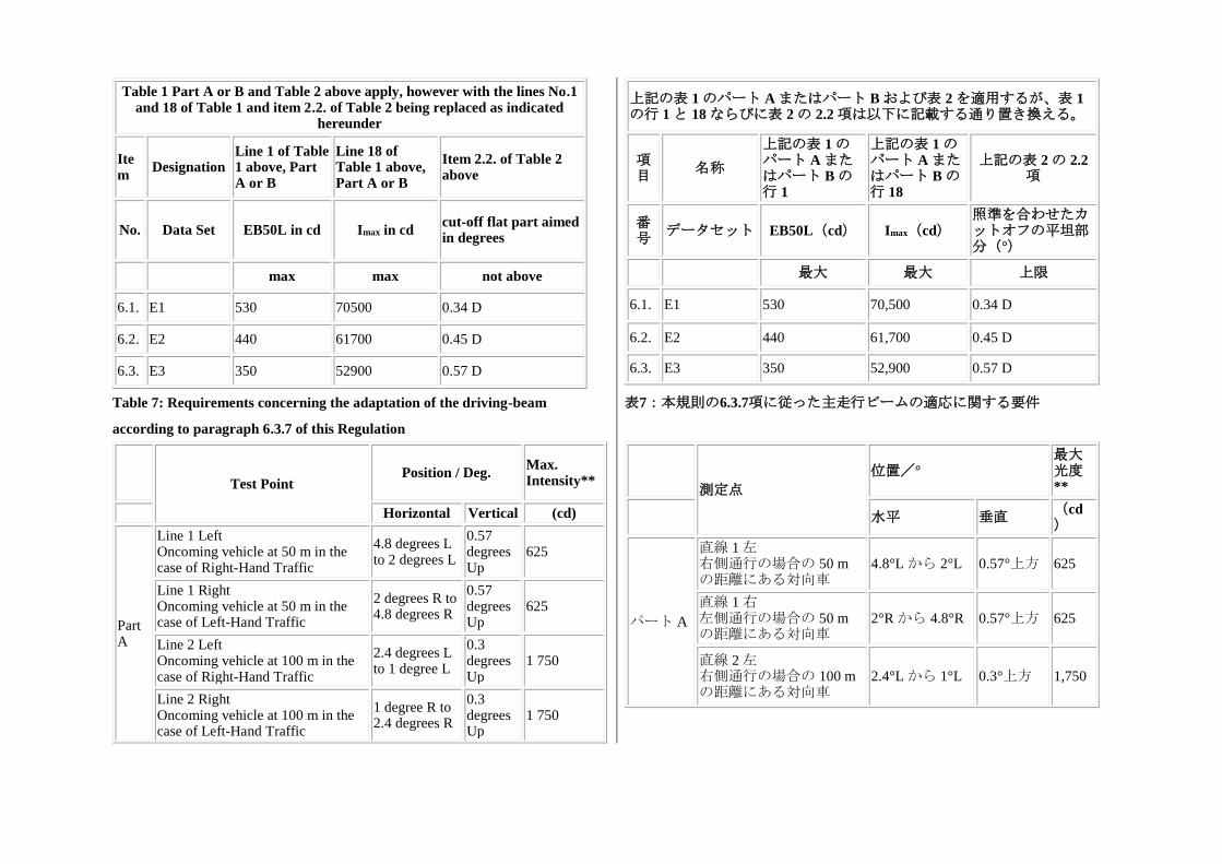
Table 1 Part A or B and Table 2 above apply, however with the lines No.1 and 18 of Table 1 and item 2.2. of Table 2 being replaced as indicated
hereunder
Item
Designation Line 1 of Table 1 above, Part A or B
Line 18 of Table 1 above, Part A or B
Item 2.2. of Table 2 above
No. Data Set EB50L in cd Imax in cd cut-off flat part aimed in degrees
max max not above
6.1. E1 530 70500 0.34 D
6.2. E2 440 61700 0.45 D
6.3. E3 350 52900 0.57 D
上記の表 1 のパート A またはパート B および表 2 を適用するが、表 1の行 1 と 18 ならびに表 2 の 2.2 項は以下に記載する通り置き換える。
項目
名称
上記の表 1 のパート A またはパート B の行 1
上記の表 1 のパート A またはパート B の行 18
上記の表 2 の 2.2項
番号
データセット EB50L(cd) Imax(cd) 照準を合わせたカットオフの平坦部分(°)
最大 最大 上限
6.1. E1 530 70,500 0.34 D
6.2. E2 440 61,700 0.45 D
6.3. E3 350 52,900 0.57 D
Table 7: Requirements concerning the adaptation of the driving-beam
according to paragraph 6.3.7 of this Regulation
表7:本規則の6.3.7項に従った主走行ビームの適応に関する要件
Test Point
Position / Deg. Max. Intensity**
Horizontal Vertical (cd)
Part A
Line 1 Left Oncoming vehicle at 50 m in the case of Right-Hand Traffic
4.8 degrees L to 2 degrees L
0.57 degrees Up
625
Line 1 Right Oncoming vehicle at 50 m in the case of Left-Hand Traffic
2 degrees R to 4.8 degrees R
0.57 degrees Up
625
Line 2 Left Oncoming vehicle at 100 m in the case of Right-Hand Traffic
2.4 degrees L to 1 degree L
0.3 degrees Up
1 750
Line 2 Right Oncoming vehicle at 100 m in the case of Left-Hand Traffic
1 degree R to 2.4 degrees R
0.3 degrees Up
1 750
測定点
位置/° 最大光度**
水平 垂直 (cd)
パート A
直線 1 左 右側通行の場合の 50 mの距離にある対向車
4.8°L から 2°L 0.57°上方 625
直線 1 右 左側通行の場合の 50 mの距離にある対向車
2°R から 4.8°R 0.57°上方 625
直線 2 左 右側通行の場合の 100 mの距離にある対向車
2.4°L から 1°L 0.3°上方 1,750
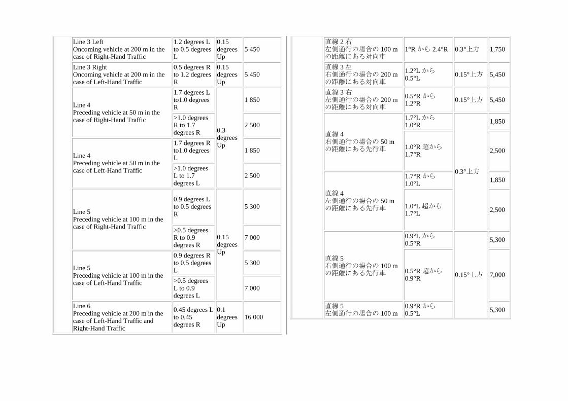
Line 3 Left Oncoming vehicle at 200 m in the case of Right-Hand Traffic
1.2 degrees L to 0.5 degrees L
0.15 degrees Up
5 450
Line 3 Right Oncoming vehicle at 200 m in the case of Left-Hand Traffic
0.5 degrees R to 1.2 degrees R
0.15 degrees Up
5 450
Line 4 Preceding vehicle at 50 m in the case of Right-Hand Traffic
1.7 degrees L to1.0 degrees R
0.3 degrees Up
1 850
>1.0 degrees R to 1.7 degrees R
2 500
Line 4 Preceding vehicle at 50 m in the case of Left-Hand Traffic
1.7 degrees R to1.0 degrees L
1 850
>1.0 degrees L to 1.7 degrees L
2 500
Line 5 Preceding vehicle at 100 m in the case of Right-Hand Traffic
0.9 degrees L to 0.5 degrees R
0.15 degrees Up
5 300
>0.5 degrees R to 0.9 degrees R
7 000
Line 5 Preceding vehicle at 100 m in the case of Left-Hand Traffic
0.9 degrees R to 0.5 degrees L
5 300
>0.5 degrees L to 0.9 degrees L
7 000
Line 6 Preceding vehicle at 200 m in the case of Left-Hand Traffic and Right-Hand Traffic
0.45 degrees L to 0.45 degrees R
0.1 degrees Up
16 000
直線 2 右 左側通行の場合の 100 mの距離にある対向車
1°R から 2.4°R 0.3°上方 1,750
直線 3 左 右側通行の場合の 200 mの距離にある対向車
1.2°L から0.5°L
0.15°上方 5,450
直線 3 右 左側通行の場合の 200 mの距離にある対向車
0.5°R から1.2°R
0.15°上方 5,450
直線 4 右側通行の場合の 50 mの距離にある先行車
1.7°L から1.0°R
0.3°上方
1,850
1.0°R 超から1.7°R
2,500
直線 4 左側通行の場合の 50 mの距離にある先行車
1.7°R から1.0°L
1,850
1.0°L 超から1.7°L
2,500
直線 5 右側通行の場合の 100 mの距離にある先行車
0.9°L から0.5°R
0.15°上方
5,300
0.5°R 超から0.9°R
7,000
直線 5 左側通行の場合の 100 m
0.9°R から0.5°L
5,300
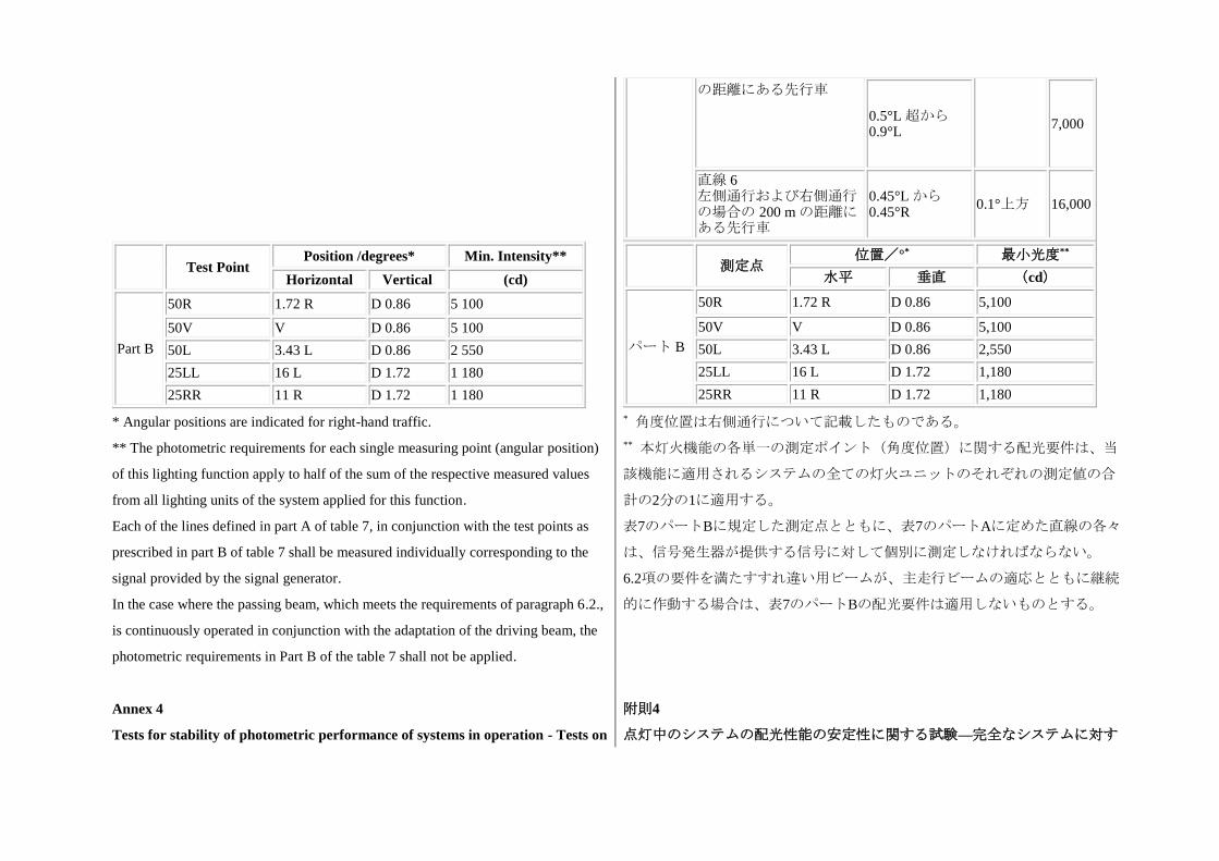
の距離にある先行車
0.5°L 超から0.9°L
7,000
直線 6 左側通行および右側通行の場合の 200 m の距離にある先行車
0.45°L から0.45°R
0.1°上方 16,000
Test Point Position /degrees* Min. Intensity**
Horizontal Vertical (cd)
Part B
50R 1.72 R D 0.86 5 100
50V V D 0.86 5 100
50L 3.43 L D 0.86 2 550
25LL 16 L D 1.72 1 180
25RR 11 R D 1.72 1 180
測定点 位置/°* 最小光度**
水平 垂直 (cd)
パート B
50R 1.72 R D 0.86 5,100
50V V D 0.86 5,100
50L 3.43 L D 0.86 2,550
25LL 16 L D 1.72 1,180
25RR 11 R D 1.72 1,180
* Angular positions are indicated for right-hand traffic.
** The photometric requirements for each single measuring point (angular position)
of this lighting function apply to half of the sum of the respective measured values
from all lighting units of the system applied for this function.
Each of the lines defined in part A of table 7, in conjunction with the test points as
prescribed in part B of table 7 shall be measured individually corresponding to the
signal provided by the signal generator.
In the case where the passing beam, which meets the requirements of paragraph 6.2.,
is continuously operated in conjunction with the adaptation of the driving beam, the
photometric requirements in Part B of the table 7 shall not be applied.
* 角度位置は右側通行について記載したものである。
** 本灯火機能の各単一の測定ポイント(角度位置)に関する配光要件は、当
該機能に適用されるシステムの全ての灯火ユニットのそれぞれの測定値の合
計の2分の1に適用する。
表7のパートBに規定した測定点とともに、表7のパートAに定めた直線の各々
は、信号発生器が提供する信号に対して個別に測定しなければならない。
6.2項の要件を満たすすれ違い用ビームが、主走行ビームの適応とともに継続
的に作動する場合は、表7のパートBの配光要件は適用しないものとする。
Annex 4
Tests for stability of photometric performance of systems in operation - Tests on
附則4
点灯中のシステムの配光性能の安定性に関する試験—完全なシステムに対す
complete systems
Tests on complete systems
Once the photometric values have been measured according to the prescriptions of
this Regulation, in the point of Emax for driving beam and in points HV, 50V and
B50L (or R), whichever applies for passing beam, a complete system sample shall be
tested for stability of photometric performance in operation.
For the purpose of this annex:
(a) "Complete system" shall be understood to mean the complete right and left side of
a system itself including electronic light source control-gear(s) and/or supply and
operating device(s) and those surrounding body parts and lamps which could
influence its thermal dissipation. Each installation unit of the system and lamp(s)
and/or LED module, if any, of the complete system may be tested separately;
(b) "Test sample" in the following text means correspondingly either the "complete
system" or the installation unit under test;
(c) The expression "light source" shall be understood to comprise also any single
filament of a filament lamp, LED modules or light emitting parts of a LED module.
The tests shall be carried out:
(a) In a dry and still atmosphere at an ambient temperature of 23 degrees C +/- 5
degrees C, the test sample being mounted on a base representing the correct
installation on the vehicle;
(b) In case of replaceable light sources: using a mass production filament light
source, which has been aged for at least one hour, or a mass production gas-
discharge light source, which has been aged for at least 15 hours or a mass
production LED module which has been aged for at least 48 hours and cooled down
る試験
完全なシステムに対する試験
本規則の規定に従って、主走行ビームについてはEmaxの点で、すれ違い用ビ
ームについてはHV、50V及びB50L(又はR)のうちいずれか該当する点で配
光測定値を測定した後に完全なシステム供試品を試験して作動中の配光性能
の安定性試験を実施しなければならない。
本附則の目的においては、
(a) 「完全なシステム」とは、電子式光源制御装置及び/又は給電及び操作
装置を含む右側若しくは左側の完全なシステム本体、システムの熱散逸に影
響を及ぼす可能性がある周辺のボディ部品及び灯火をいうものとする。シス
テムの各取り付けユニットと完全なシステムの灯火及び/又はLEDモジュー
ルを有する場合は、個別に試験することができる。
(b) 以下の条文において「供試品」とは、該当する試験に応じて「完全なシ
ステム」又は取り付けユニットのいずれかをいう。
(c) 「光源」という表現は、フィラメント電球の個々のフィラメント、LED
モジュール又はLEDモジュールの発光部分を成すものとする。
試験は、以下の通りに実施しなければならない。
(a) 供試品は、乾燥、無風、周囲温度が23℃±5℃の環境下で、車両取り付け
状態を再現した試験台に取り付けて実施する。
(b) 交換式光源の場合:少なくとも1時間点灯させた量産フィラメント電球又
は少なくとも15時間点灯させた量産ガス放電光源、又は少なくとも48時間点
灯させた量産LEDモジュールを用いて実施する。当該光源は、本規則に規定
された試験を開始する前に周囲温度まで冷ます。申請者により提供された
to ambient temperature before starting the tests as specified in this Regulation. The
LED modules supplied by the applicant shall be used.
(c) In the case of a system providing an adaptation of the driving-beam, the driving-
beam shall be in the maximum condition if activated.
The measuring equipment shall be equivalent to that used during type approval tests
of the test samples of the system. The system or part(s) thereof shall, prior to the
subsequent tests, be set to the neutral state.
The test sample shall be operated on passing beam without being dismounted from or
readjusted in relation to its test fixture. The light source used shall be a light source
of the category specified for that headlamp.
LEDモジュールを用いなければならない。
(c) 主走行ビームの適応を提供するシステムの場合は、主走行ビームは、作
動したときには最大条件になければならない。
測定機器は、システムの供試品の型式の認可試験中に使用した機器と同等の
ものを用いなければならない。システム又はその部品は、次の試験の前に、
中立状態に設定しなければならない。
供試品は、試験装置から取り外したり、試験装置との位置関係を再調節した
りせずに、すれ違い用ビームで作動させなければならない。使用する光源
は、当該前照灯に対して規定されたカテゴリーの光源でなければならない。
1. Test for stability of photometric performance 1. 配光性能安定性の試験
1.1.
Clean test sample
Each test sample shall be operated for 12 hours as described in paragraph 1.1.1. and
checked as prescribed in paragraph 1.1.2. below.
1.1.
清潔な供試品
各供試品は、1.1.1項に定める通り12時間点灯し、下記1.1.2項に規定されてい
る通り確認しなければならない。
1.1.1.
Test procedure
1.1.1.
試験手順
1.1.1.1.
Test sequence
(a)In the case where a test sample is designed to provide only one lighting function
(driving beam or passing beam) and not more than one class in case of passing beam,
the corresponding light source(s) is/are lit for the time1 specified in paragraph 1.1.
above;
1 When the "test sample" is grouped and/or reciprocally incorporated with signaling
1.1.1.1.
試験順序
(a) 供試品が一つの灯火機能(主走行ビーム又はすれ違い用ビーム)のみを
提供し、すれ違い用ビームの場合には複数の等級を提供しないように設計さ
れている場合には、対応する光源を上記1.1項に規定した時間にわたり点灯さ
せる。1
1 「供試品」が標識灯との間で集合式及び/又は兼用式の場合、試験中は標
lamps, the latter shall be lit for the duration of the test, except for a daytime running
lamp. In the case of a direction indicator lamp, it shall be lit in flashing operation
mode with an on/off time ratio of approximately one to one.
(b)In the case where a test sample provides more than one function or class of
passing beam according to this Regulation: if the applicant declares that each
specified function or class of passing beam of the test sample has its own light
source(s), being exclusively lit2 at a time, the test shall be carried out in accordance
with this condition, activating1 the most power consuming mode of each specified
function or class of passing beam successively for the same (equally divided) part of
the time specified in paragraph 1.1.
In all other cases1,2, the test sample shall be subjected to the following cycle test for
each, the mode(s) of class C passing beam, the class V passing beam, the class E
passing beam and the class W passing beam, whatever is provided or partly provided
by the test sample, for the same (equally divided) part of the time specified in
paragraph 1.1.:
1 When the "test sample" is grouped and/or reciprocally incorporated with signaling
lamps, the latter shall be lit for the duration of the test, except for a daytime running
lamp. In the case of a direction indicator lamp, it shall be lit in flashing operation
mode with an on/off time ratio of approximately one to one.
2 Should additional light sources be simultaneously lit when headlamp flashing is
used, this shall not be considered as being normal use of the light sources
simultaneously.
15 minutes, first, e.g. class C passing beam mode lit with its most power-consuming
mode for straight road conditions;
5 minutes, same passing beam mode lit as before and, additionally, all light sources3
識灯を点灯させなければならない。但し、昼間走行灯を除く。方向指示器の
場合は、オン/オフの時間比をおよそ1対1にして点滅作動配光形態で点灯さ
せなければならない。
(b) 供試品が本規則に従って機能又はすれ違い用ビームの等級を複数提供す
る場合:供試品において、規定されたそれぞれの灯火機能又はすれ違い用ビ
ームの等級が固有の光源を有し、一度に一つずつのみ点灯する2と申請者が申
告している場合、試験はこの条件に従って実施し、指定されたそれぞれの機
能又はすれ違い用ビームの等級において各々電力を最も多く消費する配光形
態を1.1項に規定された時間と同等の(均等に分割された)時間にわたって連
続して点灯させなければならない。1
その他のすべての場合においては1, 2、供試品は、当該供試品で提供されるか
部分的に提供されるC等級すれ違い用ビーム、V等級すれ違い用ビーム、E等
級すれ違い用ビーム及びW等級すれ違い用ビームの配光形態のそれぞれにつ
いて以下のサイクル試験を1.1項に規定された時間と同等の(均等に分割され
た)時間にわたって実施しなければならない。
1 「供試品」が標識灯との間で集合式及び/又は兼用式の場合、試験中は標
識灯を点灯させなければならない。但し、昼間走行灯を除く。方向指示器の
場合は、オン/オフの時間比をおよそ1対1にして点滅作動配光形態で点灯さ
せなければならない。
2 前照灯の点滅が利用されているときに追加光源が同時に点灯する場合に
は、光源の通常の同時使用とはみなしてはならない。
15分間にわたり、まず、例えばC等級のすれ違い用ビームの配光形態を、電
力を最も多く消費する配光形態で直線道路の状態で点灯させる。
5分間にわたり、同じすれ違い用ビームの配光形態を前段と同様に点灯させ、
of the test sample, which are possible to be lit at the same time, according to the
applicants declaration;
3 All light sources of lighting functions even if no approval is sought according to
this Regulation must be taken into account, except those covered by footnote 2.
After having reached the said (equally divided) part of the time specified in
paragraph 1.1., the above cycle test shall be performed with the second, third and
fourth class of passing beam, if applicable, in the above order;
(c)In the case where a test sample includes other grouped lighting function(s), all the
individual functions shall be lit simultaneously for the time specified in (a) or (b)
above for individual lighting functions, according to the manufacturer's
specifications;
(d)In the case of a test sample designed to provide a passing beam bending mode or a
mode or function which is activated for a short time with an additional light source
being energized, said light source shall simultaneously be switched on for 1 minute,
and switched off for 9 minutes during the activation of the passing beam only,
specified in (a) or (b) above.
それに加えて当該供試品の光源3で申請者の申告に従って同時に点灯が可能と
されているもののすべてを同時に点灯させる。
3 脚注2の対象となる場合を除き、本規則に従って認可が求められない場合で
あっても、灯火機能のすべての光源を考慮に入れなければならない。
1.1項に規定した時間と同等の(均等に分割された)時間に達した後、第2、
第3及び第4のすれ違い用ビームの等級(該当する場合)について、上述した
順番で上記のサイクル試験を実施しなければならない。
(c) 供試品にその他の集合式灯火機能が含まれている場合、車両メーカー等
の仕様に従って、個々の灯火機能について上記(a)又は(b)に指定した時間にわ
たって個々の機能をすべて同時に点灯させなければならない。
(d) すれ違い用ビームの曲線道路用配光形態、又は追加光源に電圧を印加し
て短時間作動する配光形態若しくは機能を提供するよう設計されている供試
品の場合、上記の光源は、上記(a)又は(b)に規定されているすれ違い用ビーム
の作動中のみ、1分間にわたって同時にスイッチを入れた状態にした後、9分
間にわたってスイッチを切った状態にしなければならない。
1.1.1.2.
Test voltage
The voltage shall be applied to the terminals of the test sample as follows:
(a) In case of replaceable filament light source(s) operated directly under vehicle
voltage system conditions: the test shall be performed at 6.3 V, 13.2 V or 28.0 V as
applicable, except if the applicant specifies that the test sample may be used at a
different voltage. In this case, the test shall be carried out with the filament light
source operated at the highest voltage that can be used.
(b) In case of replaceable gas discharge light source(s): The test voltage for the
1.1.1.2.
試験電圧
以下の通りに供試品の端子に電圧をかけなければならない。
(a) 車両電圧システムの条件下で直接作動する交換式フィラメント光源の場
合:試験は、6.3V、13.2V又は28.0V(該当する電圧)において実施しなけれ
ばならない。但し、これらと異なる電圧で供試品を使用してもよいことを申
請者が規定している場合は例外とする。この場合には、試験は、使用可能な
最も高い電圧で作動させたフィラメント光源を用いて実施しなければならな
い。
electronic light source control-gear is 13.2 + 0.1 volts for 12 V vehicle voltage
system, or otherwise specified in the application for approval.
(c) In the case of non-replaceable light source operated directly under vehicle voltage
system conditions: All measurements on lighting units equipped with nonreplaceable
light sources (filament light sources and/or others) shall be made at 6.3V, 13.2V or
28.0 V or at other voltages according to the vehicle voltage system as specified by
the applicant respectively.
(d) In the case of light sources, replaceable or non-replaceable, being operated
independently from vehicle supply voltage and fully controlled by the system, or, in
the case of light sources supplied by a supply and operating device, the test voltages
as specified above shall be applied to the input terminals of that device. The test
laboratory may require from the manufacturer the supply and operating device or a
special power supply needed to supply the light source(s).
(e) LED module(s) shall be measured at 6.3V, 13.2V or 28 V respectively, if not
otherwise specified within this Regulation. LED module(s) operated by an electronic
light source control gear, shall be measured as specified by the applicant.
(f) Where signaling lamps are grouped, combined or reciprocally incorporated into
the test sample and operating at voltages other than the nominal rated voltages of 6
V, 12 V or 24 V respectively, the voltage shall be adjusted as declared by the
manufacturer for the correct photometric functioning of that lamp.
(b) 交換式ガス放電光源の場合:電子式光源制御装置の試験電圧は、12Vの車
両電圧システムについては13.2+0.1Vとし、そうでない場合は認可申請に記載
されているボルト数とする。
(c) 車両の電圧システムの条件下で直接作動する非交換式光源の場合:非交
換式光源を装備した灯火ユニット(フィラメント光源及び/又はその他の光
源)に対する測定の一切は、6.3V、13.2V又は28.0Vとするか、申請者が指定
した車両電圧システムに応じたその他の電圧で実施しなければならない。
(d) 車両の供給電圧から独立して作動し、システムによって完全に制御され
る光源(交換可能光源か非交換式光源を問わない)の場合、又は給電及び操
作装置によって給電される光源の場合は、上述した試験電圧を当該装置の入
力端子に印加しなければならない。試験機関は、光源に給電するために必要
な給電及び操作装置又は特殊電源を車両メーカー等に要求することができ
る。
(e) LEDモジュールは、本規則に別段の規定がない限り、6.3V、13.2V又は28V
の各電圧で測定しなければならない。電子式光源制御装置により作動させる
LEDモジュールは、申請者が指定する通りに測定しなければならない。
(f) 信号灯が供試品との集合式、結合式又は兼用式であり、公称定格電圧
6V、12V又は24V(該当する電圧)以外の電圧で作動する場合には、当該灯
火の配光が正しく機能するよう車両メーカー等が規定した通りに、電圧を調
節しなければならない。
1.1.2.
Test results
1.1.2.
試験結果
1.1.2.1. 1.1.2.1.
Visual inspection:
Once the test sample has been stabilized to the ambient temperature, the test sample
lens and the external lens, if any, shall be cleaned with a clean, damp cotton cloth. It
shall then be inspected visually; no distortion, deformation, cracking or change in
color of either the test sample lens or the external lens, if any, shall be noticeable.
目視検査
供試品が周囲温度で安定したら、湿った清潔な綿布で供試品のレンズ及び該
当する場合には外部レンズの汚れを取らなければならない。次に、目視検査
を実施しなければならない。その結果、供試品のレンズ又は該当する場合に
は外部レンズのいずれにも、歪み、変形、亀裂や変色が確認されないものと
する。
1.1.2.2.
Photometric test:
To comply with the requirements of this Regulation, the photometric values shall be
verified in the following points:
Class C passing-beam and each specified other passing-beam class: 50V, B50L, and
25RR, if applicable.
Driving-beam, under neutral state conditions: point of Imax.
Another aiming may be carried out to allow for any deformation of the test sample
base due to heat (the change of the position of the cut-off line is covered in
paragraph 2. of this annex).
Except for points B50L, a 10 per cent discrepancy between the photometric
characteristics and the values measured prior to the test is permissible including the
tolerances of the photometric procedure. The value measured at point B50L shall not
exceed the photometric value measured prior to the test by more than 170 cd.
1.1.2.2.
配光測定試験:
本規則の要件に適合するためには、以下の測定点において配光測定値を確認
しなければならない。
C等級すれ違い用ビーム及びその他の規定された等級のすれ違い用ビーム:
50V、B50L、及び25RR(該当する場合)
中立状態での主走行ビーム:Imaxの測定点
熱による供試品試験台の変形を考慮するために、再度照準調整を実施するこ
とができる。(カットオフラインの位置の変化は、本附則の2項で扱う。)
測定点B50Lを除き、配光特性と試験前の測定値との差は、配光測定手順の公
差を含め、10%を許容する。測定点B50Lでの測定値は、試験前に測定された
配光測定値が170cdを超えて上回らないものとする。
1.2.
Dirty test sample
After being tested as specified in paragraph 1.1. above, the test sample shall be
operated for one hour as described in paragraph 1.1.1. for each function or class of
passing beam4, after being prepared as prescribed in paragraph 1.2.1., and checked as
1.2.
汚れた供試品
上記1.1項に規定されている通り試験を実施した後、供試品は、1.2.1項に規定
した通り準備し、すれ違い用ビームの各機能又は等級について1.1.1項で規定
したサイクルで1時間にわたって作動させ4、1.1.2項に規定した通り確認しな
prescribed in paragraph 1.1.2.; after each test a sufficient cooling down period must
be assured.
4 The class W passing beam, if any, is disregarded for lighting units providing or
contributing to any other passing beam class or lighting function.
ければならない。各試験の後で、十分な冷却期間を確保しなければならな
い。
4 W等級すれ違い用ビーム(該当する場合)は、他のすれ違い用ビームの等級
又は灯火機能を提供するかこれに寄与する灯火ユニットでは試験を要しな
い。
1.2.1.
Preparation of the test sample
Test mixture
1.2.1.
供試品の準備
試験混合物
1.2.1.1.
For a system or parts thereof with the outside lens in glass, a mixture of water and
polluting agent to be applied to the test sample shall be composed of:
9 parts by weight of silica sand with a particle size of 0-100 micro meter
corresponding to distribution prescribed in paragraph 1.2.1.3.;
1 part by weight of vegetable carbon dust (beechwood) with a particle size of 0-100
micro meter;
0.2 parts by weight of NaCMC5, and
5 NaCMC represents the sodium salt of carboxymethylcellulose, customarily referred
to as CMC. The NaCMC used in the dirt mixture shall have a degree of substitution
(DS) of 0.6-0.7 and a viscosity of 200-300 cP for a 2 per cent solution at 20 degrees
C.
an appropriate quantity of distilled water with a conductivity of less than 1 mS/m.
1.2.1.1.
ガラス製の外側レンズを有するシステム又はその部品の場合:供試品に塗布
する水と汚染剤の混合物は、以下の成分で構成されなければならない。
重量比で9の割合:1.2.1.3項に規定する分布に対応する粒子サイズ0-100μmの
珪砂
重量比で1の割合:粒子サイズ0-100μmの植物性炭素粉(ブナ材)
重量比で0.2の割合:NaCMC5、及び、
5 NaCMCは、カルボキシメチルセルロースのナトリウム塩のことであり、一
般にはCMCと称される。汚れた混合物に使用されるNaCMCは、20℃の2%溶
液において、置換度(DS)が0.6から0.7、粘度が200から300cPとする。
適量:導電率が1mS/m未満の蒸留水
1.2.1.2.
For a system or parts thereof with the outside lens in plastic material, the mixture of
water and polluting agent to be applied to the test sample shall be composed of:
9 parts by weight of silica sand with a particle size of 0-100 micro meter
1.2.1.2.
プラスチック材料の外側レンズを有するシステム又はその部品の場合、供試
品に塗布する水と汚染剤の混合物は、以下の成分で構成されなければならな
い。
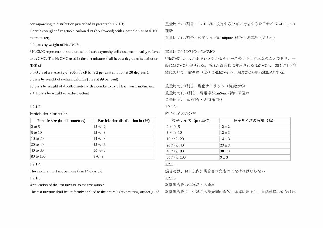
corresponding to distribution prescribed in paragraph 1.2.1.3;
1 part by weight of vegetable carbon dust (beechwood) with a particle size of 0-100
micro meter;
0.2 parts by weight of NaCMC5;
5 NaCMC represents the sodium salt of carboxymethylcellulose, customarily referred
to as CMC. The NaCMC used in the dirt mixture shall have a degree of substitution
(DS) of
0.6-0.7 and a viscosity of 200-300 cP for a 2 per cent solution at 20 degrees C.
5 parts by weight of sodium chloride (pure at 99 per cent);
13 parts by weight of distilled water with a conductivity of less than 1 mS/m; and
2 + 1 parts by weight of surface-actant.
重量比で9の割合:1.2.1.3項に規定する分布に対応する粒子サイズ0-100μmの
珪砂
重量比で1の割合:粒子サイズ0-100μmの植物性炭素粉(ブナ材)
重量比で0.2の割合:NaCMC5
5 NaCMCは、カルボキシメチルセルロースのナトリウム塩のことであり、一
般にはCMCと称される。汚れた混合物に使用されるNaCMCは、20℃の2%溶
液において、置換度(DS)が0.6から0.7、粘度が200から300cPとする。
重量比で5の割合:塩化ナトリウム(純度99%)
重量比で13の割合:導電率が1mS/m未満の蒸留水
重量比で2+1の割合:表面作用材
1.2.1.3.
Particle-size distribution
1.2.1.3.
粒子サイズの分布
Particle size (in micrometres) Particle-size distribution in (%)
0 to 5 12 +/- 2
5 to 10 12 +/- 3
10 to 20 14 +/- 3
20 to 40 23 +/- 3
40 to 80 30 +/- 3
80 to 100 9 +/- 3
粒子サイズ(μm単位) 粒子サイズの分布(%)
0 から 5 12 ± 2
5 から 10 12 ± 3
10 から 20 14 ± 3
20 から 40 23 ± 3
40 から 80 30 ± 3
80 から 100 9 ± 3
1.2.1.4.
The mixture must not be more than 14 days old.
1.2.1.4.
混合物は、14日以内に調合されたものでなければならない。
1.2.1.5.
Application of the test mixture to the test sample
The test mixture shall be uniformly applied to the entire light- emitting surface(s) of
1.2.1.5.
試験混合物の供試品への塗布
試験混合物は、供試品の発光面の全体に均等に塗布し、自然乾燥させなけれ
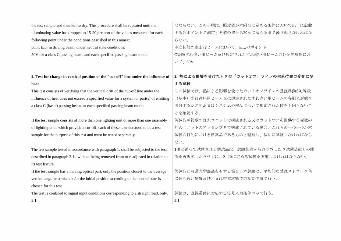
the test sample and then left to dry. This procedure shall be repeated until the
illuminating value has dropped to 15-20 per cent of the values measured for each
following point under the conditions described in this annex:
point Emax in driving beam, under neutral state conditions,
50V for a class C passing beam, and each specified passing beam mode.
ばならない。この手順は、照度値が本附則に定める条件において以下に記載
する各ポイントで測定する値の15から20%に落ちるまで繰り返さなければな
らない。
中立状態の主走行ビームにおいて、Emaxのポイント
C等級すれ違い用ビーム及び規定されたすれ違い用ビームの各配光形態にお
いて、50V
2. Test for change in vertical position of the "cut-off" line under the influence of
heat
This test consists of verifying that the vertical drift of the cut-off line under the
influence of heat does not exceed a specified value for a system or part(s) of emitting
a class C (basic) passing beam, or each specified passing beam mode.
If the test sample consists of more than one lighting unit or more than one assembly
of lighting units which provide a cut-off, each of these is understood to be a test
sample for the purpose of this test and must be tested separately.
The test sample tested in accordance with paragraph 1. shall be subjected to the test
described in paragraph 2.1., without being removed from or readjusted in relation to
its test fixture.
If the test sample has a moving optical part, only the position closest to the average
vertical angular stroke and/or the initial position according to the neutral state is
chosen for this test.
The test is confined to signal input conditions corresponding to a straight road, only.
2. 熱による影響を受けたときの「カットオフ」ラインの垂直位置の変化に関
する試験
この試験では、熱による影響を受けたカットオフラインの垂直移動がC等級
(基本)すれ違い用ビーム又は規定されたすれ違い用ビームの各配光形態を
照射するシステム又はシステムの部品について規定された値を上回らないこ
とを確認する。
供試品が複数の灯火ユニットで構成される又はカットオフを提供する複数の
灯火ユニットのアッセンブリで構成されている場合、これらの一つ一つが本
試験の目的における供試品であるものと理解し、個別に試験しなければなら
ない。
1項に従って試験される供試品は、試験装置から取り外したり試験装置との関
係を再調節したりせずに、2.1項に定める試験を実施しなければならない。
供試品に可動光学部品を有する場合、本試験は、平均的な垂直ストローク角
に最も近い位置及び/又は中立状態での初期位置で行う。
試験は、直線道路に対応する信号入力条件のみで行う。
2.1. 2.1.
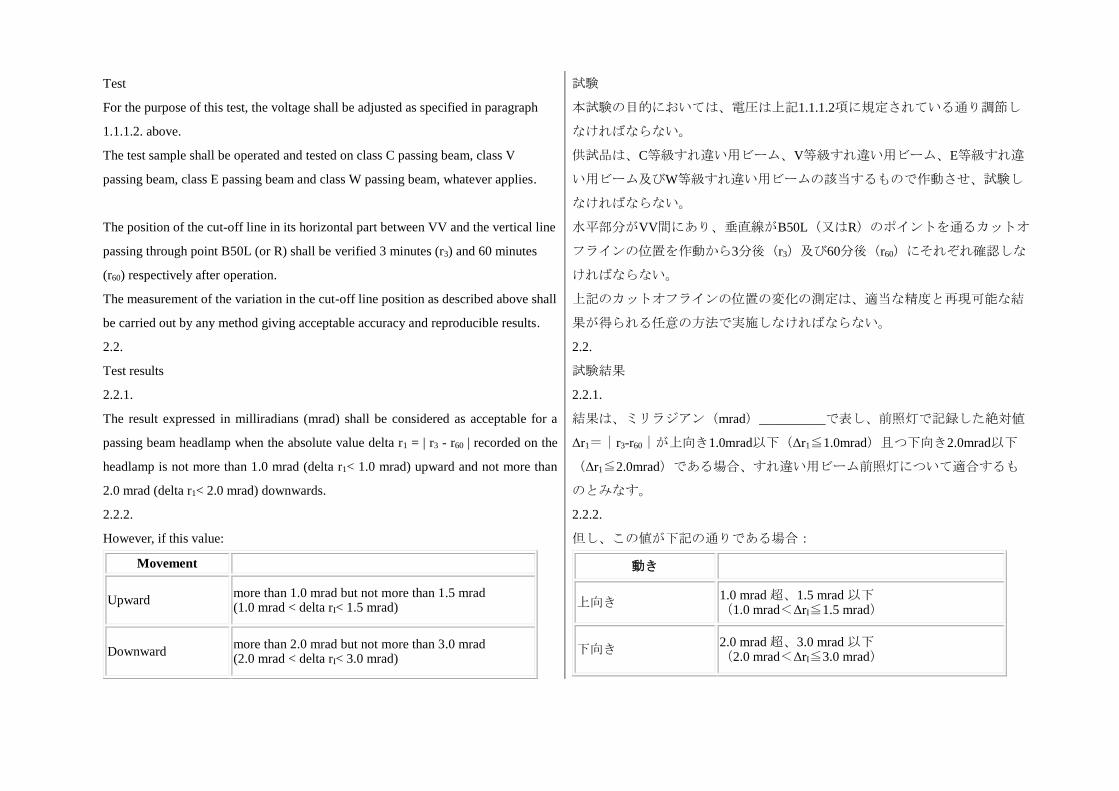
Test
For the purpose of this test, the voltage shall be adjusted as specified in paragraph
1.1.1.2. above.
The test sample shall be operated and tested on class C passing beam, class V
passing beam, class E passing beam and class W passing beam, whatever applies.
The position of the cut-off line in its horizontal part between VV and the vertical line
passing through point B50L (or R) shall be verified 3 minutes (r3) and 60 minutes
(r60) respectively after operation.
The measurement of the variation in the cut-off line position as described above shall
be carried out by any method giving acceptable accuracy and reproducible results.
試験
本試験の目的においては、電圧は上記1.1.1.2項に規定されている通り調節し
なければならない。
供試品は、C等級すれ違い用ビーム、V等級すれ違い用ビーム、E等級すれ違
い用ビーム及びW等級すれ違い用ビームの該当するもので作動させ、試験し
なければならない。
水平部分がVV間にあり、垂直線がB50L(又はR)のポイントを通るカットオ
フラインの位置を作動から3分後(r3)及び60分後(r60)にそれぞれ確認しな
ければならない。
上記のカットオフラインの位置の変化の測定は、適当な精度と再現可能な結
果が得られる任意の方法で実施しなければならない。
2.2.
Test results
2.2.
試験結果
2.2.1.
The result expressed in milliradians (mrad) shall be considered as acceptable for a
passing beam headlamp when the absolute value delta r1 = | r3 - r60 | recorded on the
headlamp is not more than 1.0 mrad (delta r1< 1.0 mrad) upward and not more than
2.0 mrad (delta r1< 2.0 mrad) downwards.
2.2.1.
結果は、ミリラジアン(mrad)__________で表し、前照灯で記録した絶対値
Δr1=|r3-r60|が上向き1.0mrad以下(Δr1≦1.0mrad)且つ下向き2.0mrad以下
(Δr1≦2.0mrad)である場合、すれ違い用ビーム前照灯について適合するも
のとみなす。
2.2.2.
However, if this value:
2.2.2.
但し、この値が下記の通りである場合:
Movement
Upward more than 1.0 mrad but not more than 1.5 mrad (1.0 mrad < delta rI< 1.5 mrad)
Downward more than 2.0 mrad but not more than 3.0 mrad (2.0 mrad < delta rI< 3.0 mrad)
動き
上向き 1.0 mrad 超、1.5 mrad 以下 (1.0 mrad<ΔrI≦1.5 mrad)
下向き 2.0 mrad 超、3.0 mrad 以下 (2.0 mrad<ΔrI≦3.0 mrad)
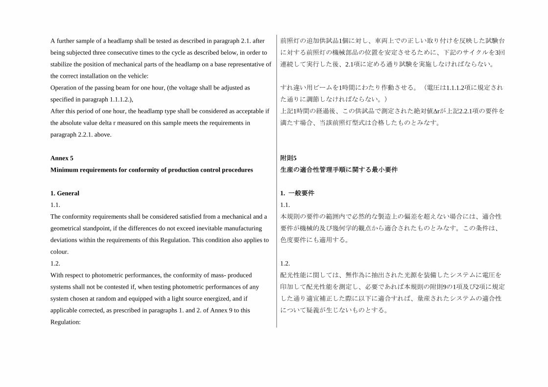
A further sample of a headlamp shall be tested as described in paragraph 2.1. after
being subjected three consecutive times to the cycle as described below, in order to
stabilize the position of mechanical parts of the headlamp on a base representative of
the correct installation on the vehicle:
Operation of the passing beam for one hour, (the voltage shall be adjusted as
specified in paragraph 1.1.1.2.),
After this period of one hour, the headlamp type shall be considered as acceptable if
the absolute value delta r measured on this sample meets the requirements in
paragraph 2.2.1. above.
前照灯の追加供試品1個に対し、車両上での正しい取り付けを反映した試験台
に対する前照灯の機械部品の位置を安定させるために、下記のサイクルを3回
連続して実行した後、2.1項に定める通り試験を実施しなければならない。
すれ違い用ビームを1時間にわたり作動させる。(電圧は1.1.1.2項に規定され
た通りに調節しなければならない。)
上記1時間の経過後、この供試品で測定された絶対値Δrが上記2.2.1項の要件を
満たす場合、当該前照灯型式は合格したものとみなす。
Annex 5
Minimum requirements for conformity of production control procedures
附則5
生産の適合性管理手順に関する最小要件
1. General 1. 一般要件
1.1.
The conformity requirements shall be considered satisfied from a mechanical and a
geometrical standpoint, if the differences do not exceed inevitable manufacturing
deviations within the requirements of this Regulation. This condition also applies to
colour.
1.1.
本規則の要件の範囲内で必然的な製造上の偏差を超えない場合には、適合性
要件が機械的及び幾何学的観点から適合されたものとみなす。この条件は、
色度要件にも適用する。
1.2.
With respect to photometric performances, the conformity of mass- produced
systems shall not be contested if, when testing photometric performances of any
system chosen at random and equipped with a light source energized, and if
applicable corrected, as prescribed in paragraphs 1. and 2. of Annex 9 to this
Regulation:
1.2.
配光性能に関しては、無作為に抽出された光源を装備したシステムに電圧を
印加して配光性能を測定し、必要であれば本規則の附則9の1項及び2項に規定
した通り適宜補正した際に以下に適合すれば、量産されたシステムの適合性
について疑義が生じないものとする。
1.2.1.
No value measured and corrected according to the prescriptions of paragraph 2. of
Annex 9 to this Regulation deviates unfavorably by more than 20 per cent from the
value prescribed in this Regulation:
1.2.1.
本規則の附則9の2項の規定に従って測定及び補正された値が、本規則に規定
されている値と比較して不利な方向に20%を超える偏差を生じないこと。
1.2.1.1.
For the following values of the passing beam and its modes, the maximum
unfavorable deviation may be respectively:
(a) Maximum values at point B50L 170 cd equivalent 20 per cent and 255 cd
equivalent 30 per cent;
(b) Maximum values at zone III and segment BLL: 255 cd equivalent 20 per cent and
380 cd equivalent 30 per cent;
(c) Maximum values at segments E, F1, F2 and F3: 170 cd equivalent 20 per cent
and 255 cd equivalent 30 per cent;
(d) Minimum values at BR, P, at the groups S 50 + S 50LL + S 50RR and S 100 + S
100LL + S 100RR, and those required by footnote 4 of Table 1 in Annex 3 of this
Regulation (B50L, BR, BRR, BLL): half of the required value equivalent 20 per cent
and three quarter of the required value equivalent 30 per cent.
1.2.1.1.
以下に記載するすれ違い用ビーム及びその配光形態の値については、最も不
利な偏差はそれぞれ下記のようにすることができる。
(a) ポイントB50Lにおける最大値:20%相当の170cd及び30%相当の255cd
(b) ゾーンIII及び線分BLLにおける最大値:20%相当の255cd及び30%相当の
380cd
(c) セグメントE、F1、F2及びF3における最大値:20%相当の170cd及び30%
相当の255cd
(d) BR、Pにおける最小値、グループS 50 + S 50LL + S 50RR及びS 100 + S
100LL + S 100RRにおける最小値、並びに本規則、附則3、表1の脚注4で要求
された最小値(B50L、BR、BRR、BLL):20%相当の要求値の半分及び30%
相当の要求値の4分の3
1.2.1.2.
For the driving beam, HV being situated within the isolux 0.75 Imax, a tolerance of
+20 per cent for maximum values and -20 per cent for minimum values is observed
for the photometric values at any measuring point specified in paragraph 6.3.2. of
this Regulation.
1.2.1.2.
主走行ビームについて、HVが0.75 Imaxの等照度範囲内にあるときに、本規則
の6.3.2項に規定されている各測定点の配光測定値において、最大値につき+
20%、最小値については-20%の公差が守られること。
1.2.2.
If the results of the test described above do not meet the requirements, the alignment
of the system may be changed, provided that the axis of the beam is not displaced
1.2.2.
上記の試験の結果が要件を満たさない場合、システムの照準調整を変更する
ことができる。但し、ビームの軸は、それぞれ独立して、初期の照準調整と
laterally by more than 0.5 degree to the right or left and not by more than 0.2 degree
up and down, each independently and with respect to the first aiming.
These provisions do not apply to lighting units as indicated under paragraph 6.3.1.1.
of this Regulation.
比較したときに、横方向には右左に0.5°を超えて、上下方向には0.2°を超えて
移動させてはならない。
上記の規定は、本規則の6.3.1.1項に記載されている灯火ユニットには適用し
ない。
1.2.3.
If the results of the tests described above do not meet the requirements, tests shall be
repeated using another standard (etalon) light source and/or another supply and
operating device.
1.2.3.
上記の試験の結果が要件を満たさない場合、別の標準(エタロン)光源及び
/又は別の給電及び操作装置を用いて試験を繰り返さなければならない。
1.3.
With respect to the verification of the change in vertical position of the "cut-off" line
for passing beam under the influence of heat, the following procedure shall be
applied:
One of the sampled systems shall be tested according to the procedure described in
paragraph 2.1. of Annex 4 after being subjected three consecutive times to the cycle
described in paragraph 2.2.2. of Annex 4.
The system shall be considered as acceptable if delta r does not exceed 1.5 mrad.
If this value exceeds 1.5 mrad but is not more than 2.0 mrad, a second sample shall
be subjected to the test after which the mean of the absolute values recorded on both
samples shall not exceed 1.5 mrad.
1.3.
熱による影響を受けたすれ違い用ビームにおける「カットオフ」ラインの垂
直位置の変化の確認に関し、以下の手順を適用しなければならない。
供試品となるシステムの一つを附則4の2.2.2項に定めるサイクルに3回連続し
て実施した後で附則4の2.1項に定められている手順に従って試験しなければ
ならない。
Δrが1.5mradを超えなければ、システムは合格したとみなす。
この値が1.5mradを超えても2.0mrad以下である場合は、二つ目の供試品で試
験を実施し、その結果、両供試品で記録された絶対値の平均値が1.5mrad以下
にならなければならない。
1.4.
The chromaticity co-ordinates shall be conformed to.
1.4.
色度座標に適合しなければならない。
2. Minimum requirements for verification of conformity by the manufacturer
For each type of system the holder of the approval mark shall carry out at least the
following tests, at appropriate intervals. The tests shall be carried out in accordance
2. 車両メーカー等による適合性確認の最低要件
各型式のシステムに関し、認可マークの保有者は、少なくとも以下に記載す
る試験を適当な頻度で実施しなければならない。試験は、本規則の規定に従
with the provision of this Regulation.
If any sampling shows non-conformity with regard to the type of test concerned,
further samples shall be taken and tested. The manufacturer shall take steps to ensure
the conformity of the production concerned.
って実施しなければならない。
抜取検査によって当該試験に関して不適合が判明した場合は、さらに供試品
を抜取り、試験しなければならない。車両メーカー等は、関連する生産の適
合性を確保するための措置を講じなければならない。
2.1.
Nature of tests
Tests of conformity in this Regulation shall cover the photometric characteristics and
the verification of the change in vertical position of the cut-off line for passing beam
under the influence of heat.
2.1.
試験内容
本規則における適合性の試験は、配光特性及び熱による影響を受けたすれ違
い用ビームにおけるカットオフラインの垂直位置の変化の確認を対象としな
ければならない。
2.2.
Methods used in tests
2.2.
試験方法
2.2.1.
Tests shall generally be carried out in accordance with the methods set out in this
Regulation.
2.2.1.
試験は、一般に本規則に定める方法に従って実施しなければならない。
2.2.2.
In any test of conformity carried out by the manufacturer, equivalent methods may
be used with the consent of the competent authority responsible for approval tests.
The manufacturer is responsible for proving that the applied methods are equivalent
to those laid down in this Regulation.
2.2.2.
車両メーカー等によって実施される適合性の試験のいずれにおいても、認可
試験の実施を担当する行政官庁の同意を得れば同等の方法を使用することが
できる。車両メーカー等は、適用される方法が本規則に記載されている方法
と同等であることを証明する責任を負う。
2.2.3.
The application of paragraphs 2.2.1. and 2.2.2. above requires regular calibration of
test apparatus and its correlation with measurement made by a competent authority.
2.2.3.
上記2.2.1項及び2.2.2項を適用するにあたって、行政官庁は試験装置及び試験
装置と測定の相関性について定期的に較正することを要する。
2.2.4.
In all cases the reference methods shall be those of this Regulation, particular for the
purpose of administrative verification and sampling.
2.2.4.
すべての場合において、特に行政による確認及び抜取検査の目的では、本規
則に定める方法を基準方法としなければならない。
2.3.
Nature of sampling
Samples of systems shall be selected at random from the production of a uniform
batch. A uniform batch means a set of systems of the same type, defined according to
the production methods of the manufacturer.
The assessment shall, in general, cover series production from individual factories.
However, a manufacturer may group together records concerning the same type from
several factories provided these operate under the same quality system and quality
management.
2.3.
抜取検査の性質
システムの供試品は、均質なバッチの生産より無作為に選択しなければなら
ない。均質なバッチとは、車両メーカー等の生産方法に従って定義された同
一型式のシステムの集合を指す。
一般に、個々の工場からの量産品を評価の対象としなければならない。但
し、車両メーカー等は、同一の品質システム及び品質管理に基づき運営され
ている工場であれば、複数の工場で製造する同一型式に関する記録を一つに
して扱うことができる。
2.4.
Measured and recorded photometric characteristics
The sampled headlamps shall be subjected to photometric measurements at the
points provided for in the Regulation, the reading being limited:
To points Emax, HV1, HL and HR2 in the case of a driving beam;
1 When the driving beam is reciprocally incorporated with the passing beam, HV in
the case of the driving beam shall be the same measuring point as in the case of the
passing beam.
2 HL and HR: points on HH located at 2.6 degrees to the left and to the right of point
HV respectively.
To points B50L, HV if applicable, 50V, 75R if applicable, and 25LL in the case of
the passing beam(s) (see Figure 1 in Annex 3).
2.4.
測定及び記録される配光特性
供試品となる前照灯は、本規則に定める測定点で配光測定を実施し、記録は
以下の測定点にのみ限定する。
主走行ビームの場合、Emax、HV1、HL及びHR2の各ポイント、
1 主走行ビームがすれ違い用ビームと兼用式となっている場合、主走行ビー
ムにおけるHVは、すれ違い用ビームにおける測定点と同一でなければならな
い。
2 HL及びHR:HV点の右及び左にそれぞれ2.6°に位置するHH上の測定点
すれ違い用ビームの場合、B50L、HV(該当する場合)、50V、75R(該当す
る場合)、及び25LLの各測定点(附則3の図1参照)
2.5.
Criteria governing acceptability
The manufacturer is responsible for carrying out a statistical study of the test results
2.5.
合格判定規準
車両メーカー等は、試験結果の統計的調査を実施すると共に、本規則の9.1項
and for defining, in agreement with the Competent Authority, criteria governing
acceptability of his products in order to meet the specification laid down for
verification of conformity of products in paragraph 9.1. of this Regulation.
The criteria governing acceptability shall be such that, with a confidence level of 95
per cent, the minimum probability of passing a spot check in accordance with Annex
7 (first sampling) would be 0.95.
で製品の適合性の確認に関して規定された仕様に適合するために、行政官庁
と合意の下で自らの製品の合格判定規準を定義する責任を有する。
合格判定規準は、95%の信頼度において、附則7に準じた抜取検査(初回抜取
検査)に合格する最低確率が0.95となるように設定されなければならない。
Annex 6
Requirements for systems incorporating lenses of plastic material: testing of
lens or material samples and complete systems or part(s) of systems
附則6
プラスチック材料のレンズを組み込んだシステムの要件:レンズ又は供試材
料及び完全なシステム又はシステムの部品の試験
1. General specifications 1. 一般仕様
1.1.
The samples supplied pursuant to paragraph 2.2.4. of this Regulation shall satisfy the
specifications indicated in paragraphs 2.1. to 2.5. below.
1.1.
本規則の2.2.4項に準じて提出される供試品は、下記2.1項から2.5項に記載した
規定を満たさなければならない。
1.2.
The set of samples of complete systems or part thereof supplied pursuant to
paragraph 2.2.3. of this Regulation and incorporating lenses of plastic material shall,
with regard to the lens material, satisfy the specifications indicated in paragraph 2.6.
below.
1.2.
プラスチック材料レンズを組み込み、本規則の2.2.3項に準じて提供される完
全なシステム又はその部品の供試品2個は、レンズの材料に関し、下記2.6項
に記す規定を満たさなければならない。
1.3.
The samples of lenses of plastic material or samples of material shall be subjected,
with the reflector to which they are intended to be fitted (where applicable), to
approval tests in the chronological order indicated in Table A reproduced in
Appendix 1 to this annex.
1.3.
プラスチック材料レンズの供試品又は供試材料は、(該当する場合)装着す
る対象となるリフレクターと共に、本附則の付録1に再掲した表Aに示す実施
手順で認可試験を実施しなければならない。
1.4.
However, if the system manufacturer can prove that the product has already passed
the tests prescribed in paragraphs 2.1. to 2.5. below, or the equivalent tests pursuant
to another Regulation, those tests do not need to be repeated; only the tests
prescribed in Appendix 1, Table B, shall be mandatory.
1.4.
但し、製品が下記2.1項から2.5項に規定した試験又は別の規則に準じた同等の
試験にすでに合格していることを当該システムの車両メーカー等が証明でき
る場合は、これらの試験を繰り返す必要はない。但し、この場合、付録1の表
Bに規定した試験は強制的に実施しなければならない。
1.5.
If the system or part thereof is designed for right-hand installation only, or for left-
hand installation only, tests pursuant to this annex may be done on one sample only,
at the choice of the applicant.
1.5.
システム又はシステムの部品が右側取り付け専用又は左側取り付け専用とし
て設計されている場合、本附則に準じた試験は申請者の選択により一つの供
試品のみで実施することができる。
2. Tests 2. 試験
2.1.
Resistance to temperature changes
2.1.
耐温度変化
2.1.1.
Tests
Three new samples (lenses) shall be subjected to five cycles of temperature and
humidity (RH = relative humidity) change in accordance with the following
programme:
3 hours at 40 degrees C +/- 2 degrees C and 85-95 per cent RH;
1 hour at 23 degrees C +/- 5 degrees C and 60-75 per cent RH;
15 hours at -30 degrees C +/- 2 degrees C;
1 hour at 23 degrees C +/- 5 degrees C and 60-75 per cent RH;
3 hours at 80 degrees C +/- 2 degrees C;
1 hour at 23 degrees C +/- 5 degrees C and 60-75 per cent RH;
Before this test, the samples shall be kept at 23 degrees C +/- 5 degrees C and 60-75
2.1.1.
試験
三つの新しい供試品(レンズ)を以下の手順に従って5サイクルの温度及び湿
度(RH=相対湿度)変化に曝さなければならない。
40℃ ± 2℃及び85から95%のRHにおいて3時間
23℃ ± 5℃及び60から75%のRHにおいて1時間
-30℃ ± 2℃において15時間
23℃ ± 5℃及び60から75%のRHにおいて1時間
80℃ ± 2℃において3時間
23℃ ± 5℃及び60から75%のRHにおいて1時間
この試験の前に、供試品を少なくとも4時間にわたって23℃ ± 5℃及び60から
per cent RH for at least four hours.
Note: The periods of one hour at 23 degrees C +/- 5 degrees C shall include the
periods of transition from one temperature to another which are needed in order to
avoid thermal shock effects.
75%のRHで保管しなければならない。
注:23℃ ± 5℃での1時間の期間には、熱衝撃の作用を防ぐために必要な温度
の移行期間を含まなければならない。
2.1.2.
Photometric measurements
2.1.2.
配光測定
2.1.2.1.
Method
Photometric measurements shall be carried out on the samples before and after the
test.
These measurements shall be made according to Annex 9 to this Regulation, at the
following points:
B50L and 50V for the class C passing beam lighting;
Emax for the driving beam of a system.
2.1.2.1.
方法
配光測定は、試験の前と後に供試品を用いて実施しなければならない。
これらの測定は、本規則の附則9に従って、以下の測定点において実施しなけ
ればならない。
C等級すれ違い用ビームの照明については、B50L及び50V
システムの主走行ビームについては、Emax
2.1.2.2.
Results
The variation between the photometric values measured on each sample before and
after the test shall not exceed 10 per cent including the tolerances of the photometric
procedure.
2.1.2.2.
結果
試験の前及び後に各供試品で測定した配光測定値の差は、配光測定手順の公
差を含め10%以下でなければならない。
2.2.
Resistance to atmospheric and chemical agents
2.2.
耐候性及び耐薬品性
2.2.1.
Resistance to atmospheric agents
Three new samples (lenses or samples of material) shall be exposed to radiation from
a source having a spectral energy distribution similar to that of a black body at a
2.2.1.
耐候性
3個の新しい供試品(レンズ又は供試材料)を5,500Kから6,000Kの黒体に準じ
た分光エネルギー分布を持つ放射源からの放射線に曝さなければならない。
temperature between 5,500 K and 6,000 K. Appropriate filters shall be placed
between the source and the samples so as to reduce as far as possible radiation with
wave lengths smaller than 295 nm and greater than 2,500 nm. The samples shall be
exposed to an energetic illumination of 1,200 W/m2 +/- 200
W/m2 for a period such that the luminous energy that they receive is equal to 4,500
MJ/m2 +/- 200 MJ/m2. Within the enclosure, the temperature measured on the black
panel placed on a level with the samples shall be 50 degrees C +/- 5 degrees C. In
order to ensure a regular exposure, the samples shall revolve around the source of
radiation at a speed between 1 and 5 min-1.
The samples shall be sprayed with distilled water of conductivity lower than 1 mS/m
at a temperature of 23 degrees C +/- 5 degrees C, in accordance with the following
cycle:
Spraying: 5 minutes; drying: 25 minutes.
295nm未満と2,500nm超の波長を持つ放射線が可能な限り少なくなるようにす
るため、放射源と供試品の間には適当なフィルタを配置しなければならな
い。供試品は、受ける光量が4,500MJ/m2 ± 200MJ/m2になるような期間にわた
って1,200W/m2 ± 200W/m2のエネルギー照射に曝さなければならない。試験室
の中では、供試品と同じ位置に置いた黒パネル上で測定した温度が50℃±5℃
にならなければならない。定常的な暴露を確保するために、供試品は放射源
の周りを1から5 min-1の速度で回転させなければならない。
供試品には、以下のサイクルに従って、23℃ ± 5℃の温度で1mS/m未満の導
電率を持つ蒸留水を噴霧しなければならない。
噴霧:5分間、乾燥:25分間
2.2.2.
Resistance to chemical agents
After the test described in paragraph 2.2.1. above and the measurement described in
paragraph 2.2.3.1. below have been carried out, the outer face of the said three
samples shall be treated as described in paragraph 2.2.2.2. with the mixture defined
in paragraph 2.2.2.1. below.
2.2.2.
耐薬品性
上記2.2.1項に定める試験と下記2.2.3.1項に定める測定が実施された後、上記
の3個の供試品の外側面を下記2.2.2.1項に規定されている混合物で2.2.2.2項に
定める通り実施しなければならない。
2.2.2.1.
Test mixture
The test mixture shall be composed of 61.5 per cent n-heptane, 12.5 per cent toluene,
7.5 per cent ethyl tetrachloride, 12.5 per cent trichloroethylene and 6 per cent xylene
(volume per cent).
2.2.2.1.
試験混合物
試験混合物は、61.5%のn-ヘプタン、12.5%のトルエン、7.5%の四塩化エチ
ル、12.5%のトリクロロエチレン、6%のキシレン(体積%)で構成しなけれ
ばならない。
2.2.2.2. 2.2.2.2.
Application of the test mixture
Soak a piece of cotton cloth (as per ISO 105) until saturation with the mixture
defined in paragraph 2.2.2.1. above and, within 10 seconds, apply it for 10 minutes
to the outer face of the sample at a pressure of 50 N/cm2, corresponding to an effort
of 100 N applied on a test surface of 14 x 14 mm.
During this 10-minute period, the cloth pad shall be soaked again with the mixture so
that the composition of the liquid applied is continuously identical with that of the
test mixture prescribed.
During the period of application, it is permissible to compensate the pressure applied
to the sample in order to prevent it from causing cracks.
試験混合物の塗布
綿布(ISO105に準ずる)を上記2.2.2.1項に定義した混合物で飽和するまで浸
透させる。次に、10秒間以内に、14×14mmの試験面に加えられる100Nの応力
に対応した50N/cm2の圧力を掛けて、綿布を供試品の外面に10分間あてる。
この10分間の期間中、塗布される液体の成分が所定の試験混合物の成分と同
じ状態を維持するようにするため、綿布を混合物に再度浸さなければならな
い。
塗布期間中、供試品に割れが生じることのないように供試品に加えられる圧
力を調整することができる。
2.2.2.3.
Cleaning
At the end of the application of the test mixture, the samples shall be dried in the
open air and then washed with the solution described in paragraph 2.3.
(Resistance to detergents and hydrocarbons) at 23 degrees C +/- 5 degrees C.
Afterwards the samples shall be carefully rinsed with distilled water containing not
more than 0.2 per cent impurities at 23 degrees C +/- 5 degrees C and then wiped off
with a soft cloth.
2.2.2.3.
洗浄
試験混合物の塗布終了後、供試品は屋外で乾燥させ、2.3項(洗剤及び炭化水
素に対する耐性)に定める23℃ ± 5℃の溶液で洗浄しなければならない。
その後、供試品は23℃ ± 5℃で不純物の含有率が0.2%以下の蒸留水で慎重に
洗い流してから、柔らかい布で水滴を拭き取らなければならない。
2.2.3.
Results
2.2.3.
結果
2.2.3.1.
After the test of resistance to atmospheric agents, the outer face of the samples shall
be free from cracks, scratches, chipping and deformation, and the mean variation in
transmission delta t=(T2-T3)/T2 measured on the three samples according to the
2.2.3.1.
耐候性試験の後、供試品の外面は、割れ、擦り傷、欠けや変形が一切ないも
のとし、本附則の付録2に記載されている手順に従って三つの供試品で測定し
た透過率の平均変化率Δt =(T2-T3)/T2が0.020を超えないものとする(Δtm <
procedure described in Appendix 2 to this annex shall not exceed 0.020 (delta tm <
0.020).
0.020)。
2.2.3.2.
After the test of resistance to chemical agents, the samples shall not bear any traces
of chemical staining likely to cause a variation of flux diffusion, whose mean
variation delta d =(T5-T4)/T2 measured on the three samples according to the
procedure described in Appendix 2 to this annex shall not exceed 0.020
(delta dm < 0.020).
2.2.3.2.
耐薬品性試験の後、供試品には光束拡散率の変化を引き起こすおそれのある
化学的汚染の兆候が一切ないものとし、本附則の付録2に定められている手順
に従って三つの供試品で測定した平均変化率Δd =(T5-T4)/T2が0.020を超えない
ものとする(Δtm < 0.020)。
2.2.4.
Resistance to light source radiation
If necessary the following test shall be done:
Flat samples of each light transmitting plastic component of the system are exposed
to the light of the light source. The parameters such as angles and distances of those
samples shall be the same as in the system. These samples shall have the same colour
and surface treatment, if any, as the parts of the system.
After 1,500 hours of continuous exposure, the colorimetric specification of the
transmitted light must be met with a new light source, and the surface of the samples
shall be free of cracks, scratches, scaling or deformation.
The UV-resistance testing of internal materials to light source radiation is not
necessary if light sources according to Regulation No. 37 and/or low-UV-type gas
discharge light sources and/or low-UV-type LED modules are being applied or if
provisions are taken, to shield the relevant system components from UV radiation,
e.g. by glass filters.
2.2.4.
耐光源放射
必要であれば、以下の試験を実施しなければならない。
システムの各プラスチック製透光部品の平坦な供試品を光源からの光を照射
する。これらの供試品の角度や距離などのパラメータは、システムと同一で
なければならない。各供試品は、システムの部品と同じ色及び表面加工(施
されている場合)でなければならない。
1,500時間の連続した暴露の後、新しい光源を用いたときに透過光の色度規格
が満たされなければならず、供試品の表面には、割れ、擦り傷、スケールの
発生又は変形が一切ないものとする。
協定規則第37号に準じた光源及び/又は低紫外線タイプのガス放電光源及び
/又は低紫外線タイプのLEDモジュールが使用されている場合や、例えばガ
ラスフィルタなどで関連システム構成部品を紫外線放射から保護するための
手段が講じられている場合には、光源の放射に対する内部材料の耐紫外線試
験は不要である。
2.3.
Resistance to detergents and hydrocarbons
2.3.
洗剤及び炭化水素に対する耐性
2.3.1.
Resistance to detergents
The outer face of three samples (lenses or samples of material) shall be heated to 50
degrees C +/- 5 degrees C and then immersed for five minutes in a mixture
maintained at 23 degrees C +/- 5 degrees C and composed of 99 parts distilled water
containing not more than 0.02 per cent impurities and one part alkylaryl sulphonate.
At the end of the test, the samples shall be dried at 50 degrees C +/- 5 degrees C. The
surface of the samples shall be cleaned with a moist cloth.
2.3.1.
洗剤に対する耐性
三つの供試品の外面(レンズ又は供試材料)を50℃ ± 5℃に加熱し、その
後、不純物の含有率が0.02%以下である蒸留水が99%とアルキルアリルスル
ホネートが1%で構成され、温度が23℃ ± 5℃に維持された混合物に5分間浸
さなければならない。
試験終了後、供試品は50℃ ± 5℃で乾燥させなければならない。供試品の表
面は、湿った布で拭き取らなければならない。
2.3.2.
Resistance to hydrocarbons
The outer face of these three samples shall then be lightly rubbed for one minute
with a cotton cloth soaked in a mixture composed of 70 per cent n-heptane and 30
per cent toluene (volume per cent), and shall then be dried in the open air.
2.3.2.
炭化水素に対する耐性
次に、70%のn-ヘプタンと30%のトルエン(体積%)で構成された混合物に
浸した綿布で、これら三つの供試品の外面を1分間にわたり軽くこすり、屋外
で乾燥させなければならない。
2.3.3.
Results
After the above two tests have been performed successively, the mean value of the
variation in transmission delta t=(T2-T3)/T2 measured on the three samples according
to the procedure described in Appendix 2 to this annex shall not exceed 0.010 (delta
tm< 0.010).
2.3.3.
結果
上記の二つの試験を連続して実施した後、本附則の付録2に定められている手
順に従って三つの供試品で測定した平均透過変化率Δt=(T2-T3)/T2が0.010を超
えないものとする(Δtm≦0.010)。
2.4.
Resistance to mechanical deterioration
2.4.1.
Mechanical deterioration method
The outer face of the three new samples (lenses) shall be subjected to the uniform
mechanical deterioration test by the method described in Appendix 3 to this annex.
2.4.
機械劣化に対する耐性
2.4.1.
機械劣化方法
三つの新しい供試品(レンズ)の外面に対して、本附則の付録3に定める方法
により均等な機械劣化試験を実施しなければならない。
2.4.2.
Results
After this test, the variations:
In transmission: delta t = (T2-T3) / T2
And in diffusion: delta d = (T5-T4) / T2
Shall be measured according to the procedure described in Appendix 2 in the area
specified in paragraph 2.2.4.1.1. of this Regulation. The mean value of the
three samples shall be such that:
delta tm< 0.100; delta dm< 0.050.
2.4.2.
結果
この試験後に、
透過率:Δt = (T2-T3) / T2
及び拡散率:Δd = (T5-T4) / T2
上記の変動量を本規則の2.2.4.1.1項に規定されている領域において付録2に記
載されている手順に従って測定しなければならない。三つの供試品の平均値
は、以下の通りでなければならない。
Δtm ≦ 0.100、Δdm ≦ 0.050
2.5.
Test of adherence of coatings, if any
2.5.
コーティングの接着試験(該当する場合)
2.5.1.
Preparation of the sample
A surface of 20 mm x 20 mm in area of the coating of a lens shall be cut with a razor
blade or a needle into a grid of squares approximately 2 mm x 2 mm. The pressure
on the blade or needle shall be sufficient to cut at least the coating.
2.5.1.
供試品の準備
かみそりの刃又は針を用いて、レンズのコーティングの20mm×20mmの範囲
の表面をおよそ2mm×2mm四方のマス目ができるように切れ目を入れなけれ
ばならない。刃又は針に加える圧力は、少なくともコーティングを切るため
に十分な程度でなければならない。
2.5.2.
Description of the test
Use an adhesive tape with a force adhesion of 2 N /(cm of width) +/- 20 per cent
measured under the standardized conditions specified in Appendix 4 to this annex.
This adhesive tape, which shall be at least 25 mm wide, shall be pressed for at least
five minutes to the surface prepared as prescribed in paragraph 2.5.1.
Then the end of the adhesive tape shall be loaded in such a way that the force of
adhesion to the surface considered is balanced by a force perpendicular to that
2.5.2.
試験の説明
本附則の付録4に規定した標準条件で測定したときに2N/(幅cm) ± 20%の
接着力を持つ接着テープを使用する。この接着テープは、少なくとも幅が
25mmあるものとし、2.5.1項に規定した通り準備した表面に少なくとも5分間
にわたって押し付けなければならない。
次に、接着テープの末端に対し、対象とする表面への接着力が当該表面に対
して垂直の力と均衡するように負荷を加えなければならない。この段階で、
surface. At this stage, the tape shall be torn off at a constant speed of 1.5 m/s +/- 0.2
m/s.
1.5m/s ± 0.2m/sの定速でテープを剥がさなければならない。
2.5.3.
Results
There shall be no appreciable impairment of the gridded area. Impairments at the
intersections between squares or at the edges of the cuts shall be permitted, provided
that the impaired area does not exceed 15 per cent of the gridded surface.
2.5.3.
結果
マス目を描いた領域に著しい損傷が生じないものとする。四角形の交点と切
れ目の末端の損傷については、損傷した領域がマス目を描いた表面の15%以
下であれば許容しなければならない。
2.6.
Tests of the complete system incorporating a lens of plastic material
2.6.
プラスチック材料のレンズを組み込んだ完全なシステムの試験
2.6.1.
Resistance to mechanical deterioration of the lens surface
2.6.1.
レンズ表面の機械劣化に対する耐性
2.6.1.1.
Tests
The lens of system sample No. 1 shall be subjected to the test described in paragraph
2.4.1. above.
2.6.1.1.
試験
システム供試品No. 1のレンズに、上記2.4.1項に記載する試験を実施しなけれ
ばならない。
2.6.1.2.
Results
After the test, the results of photometric measurements carried out on the system or
part thereof in accordance with this Regulation shall not exceed by more than 130
per cent the maximum values prescribed at points B50L and HV and not be more
than 90 per cent below the minimum values prescribed at point 75R, if applicable.
2.6.1.2.
結果
試験の後、本規則に従ってシステム又はシステムの部品に対して実施された
配光測定の結果は、B50L及びHVの測定点で規定された最大値の130%を上回
らないものとし、75Rの測定点で規定された最小値(該当する場合)の90%
を下回らないものとする。
2.6.2.
Test of adherence of coatings, if any
The lens of installation unit sample No. 2 shall be subjected to the test described in
paragraph 2.5. above.
2.6.2.
コーティングの接着の試験(該当する場合)
取り付けユニット供試品No. 2のレンズに、上記2.5項に定める試験を実施しな
ければならない。
3. Verification of the conformity of production 3. 生産の適合性の確認
3.1.
With regard to the materials used for the manufacture of lenses, the installation units
of a series shall be recognized as complying with this Regulation if:
3.1.
レンズの製造のために使われた材料に関しては、以下に該当する場合は量産
品の取り付けユニットが本規則に適合するものと認めなければならない。
3.1.1.
After the test for resistance to chemical agents and the test for resistance to
detergents and hydrocarbons, the outer face of the samples exhibits no cracks,
chipping or deformation visible to the naked eye (see paragraphs 2.2.2., 2.3.1. and
2.3.2.);
3.1.1.
耐薬品性の試験と洗剤及び炭化水素に対する耐性の試験の後、供試品の外面
には、目視で確認できる割れ、欠けや変形がないこと(2.2.2項、2.3.1項及び
2.3.2項参照)。
3.1.2.
After the test described in paragraph 2.6.1.1. above, the photometric values at the
points of measurement considered in paragraph 2.6.1.2. are within the limits
prescribed for conformity of production by this Regulation.
3.1.2.
上記2.6.1.1項に記述した試験の後、2.6.1.2項で考慮された測定点での配光測定
値は、生産の適合性に関して本規則によって規定された限界値の範囲内に収
まること。
3.2.
If the test results fail to satisfy the requirements, the tests shall be repeated on another
sample of systems selected at random.
3.2.
試験の結果が要件を満たさない場合は、無作為に抽出されたシステムの別の
供試品で試験を繰り返さなければならない。
Annex 6 - Appendix 1
Chronological order of approval tests
附則6-付録1
認可試験の操作順
A.
Tests on plastic materials (lenses or samples of material supplied pursuant to
paragraph 2.2.4. of this Regulation)
A.
プラスチック材料(本規則の2.2.4項に準じて提供されたレンズ又は供試材
料)に対する試験
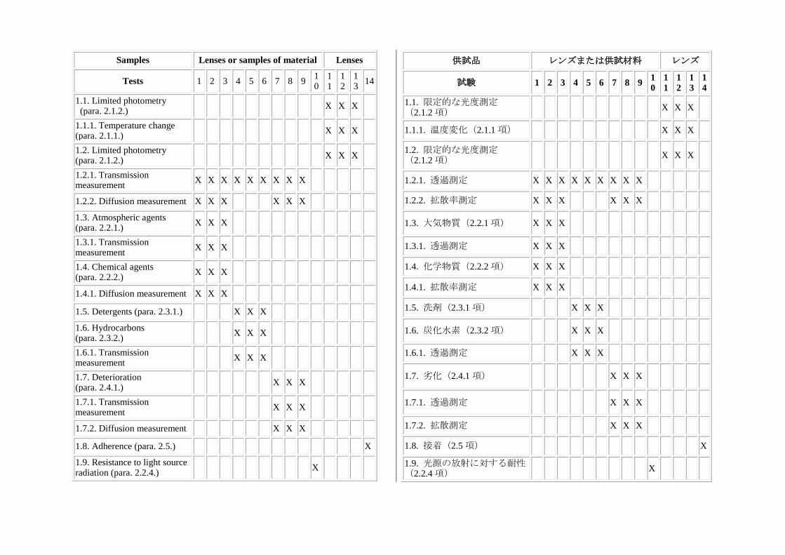
Samples Lenses or samples of material Lenses
Tests 1 2 3 4 5 6 7 8 9 10
11
12
13
14
1.1. Limited photometry (para. 2.1.2.)
X X X
1.1.1. Temperature change (para. 2.1.1.)
X X X
1.2. Limited photometry (para. 2.1.2.)
X X X
1.2.1. Transmission measurement
X X X X X X X X X
1.2.2. Diffusion measurement X X X X X X
1.3. Atmospheric agents (para. 2.2.1.)
X X X
1.3.1. Transmission measurement
X X X
1.4. Chemical agents (para. 2.2.2.)
X X X
1.4.1. Diffusion measurement X X X
1.5. Detergents (para. 2.3.1.) X X X
1.6. Hydrocarbons (para. 2.3.2.)
X X X
1.6.1. Transmission measurement
X X X
1.7. Deterioration (para. 2.4.1.)
X X X
1.7.1. Transmission measurement
X X X
1.7.2. Diffusion measurement X X X
1.8. Adherence (para. 2.5.) X
1.9. Resistance to light source radiation (para. 2.2.4.)
X
供試品 レンズまたは供試材料 レンズ
試験 1 2 3 4 5 6 7 8 9 10
11
12
13
14
1.1. 限定的な光度測定 (2.1.2 項)
X X X
1.1.1. 温度変化(2.1.1 項) X X X
1.2. 限定的な光度測定 (2.1.2 項)
X X X
1.2.1. 透過測定 X X X X X X X X X
1.2.2. 拡散率測定 X X X X X X
1.3. 大気物質(2.2.1 項) X X X
1.3.1. 透過測定 X X X
1.4. 化学物質(2.2.2 項) X X X
1.4.1. 拡散率測定 X X X
1.5. 洗剤(2.3.1 項) X X X
1.6. 炭化水素(2.3.2 項) X X X
1.6.1. 透過測定 X X X
1.7. 劣化(2.4.1 項) X X X
1.7.1. 透過測定 X X X
1.7.2. 拡散測定 X X X
1.8. 接着(2.5 項) X
1.9. 光源の放射に対する耐性 (2.2.4 項)
X
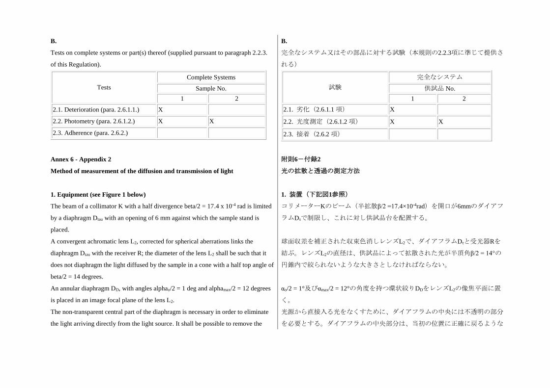
B.
Tests on complete systems or part(s) thereof (supplied pursuant to paragraph 2.2.3.
of this Regulation).
Tests
Complete Systems
Sample No.
1 2
2.1. Deterioration (para. 2.6.1.1.) X
2.2. Photometry (para. 2.6.1.2.) X X
2.3. Adherence (para. 2.6.2.)
B.
完全なシステム又はその部品に対する試験(本規則の2.2.3項に準じて提供さ
れる)
試験
完全なシステム
供試品 No.
1 2
2.1. 劣化(2.6.1.1 項) X
2.2. 光度測定(2.6.1.2 項) X X
2.3. 接着(2.6.2 項)
Annex 6 - Appendix 2
Method of measurement of the diffusion and transmission of light
附則6-付録2
光の拡散と透過の測定方法
1. Equipment (see Figure 1 below)
The beam of a collimator K with a half divergence beta/2 = 17.4 x 10⁻⁴ rad is limited
by a diaphragm Dtau with an opening of 6 mm against which the sample stand is
placed.
A convergent achromatic lens L2, corrected for spherical aberrations links the
diaphragm Dtau with the receiver R; the diameter of the lens L2 shall be such that it
does not diaphragm the light diffused by the sample in a cone with a half top angle of
beta/2 = 14 degrees.
An annular diaphragm DD, with angles alphao/2 = 1 deg and alphamax/2 = 12 degrees
is placed in an image focal plane of the lens L2.
The non-transparent central part of the diaphragm is necessary in order to eliminate
the light arriving directly from the light source. It shall be possible to remove the
1. 装置(下記図1参照)
コリメーターKのビーム(半拡散β/2 =17.4×10⁻⁴rad)を開口が6mmのダイアフ
ラムDτで制限し、これに対し供試品台を配置する。
球面収差を補正された収束色消しレンズL2で、ダイアフラムDτと受光器Rを
結ぶ。レンズL2の直径は、供試品によって拡散された光が半頂角β/2 = 14°の
円錐内で絞られないような大きさとしなければならない。
αo/2 = 1°及びαmax/2 = 12°の角度を持つ環状絞りDDをレンズL2の像焦平面に置
く。
光源から直接入る光をなくすために、ダイアフラムの中央には不透明の部分
を必要とする。ダイアフラムの中央部分は、当初の位置に正確に戻るような
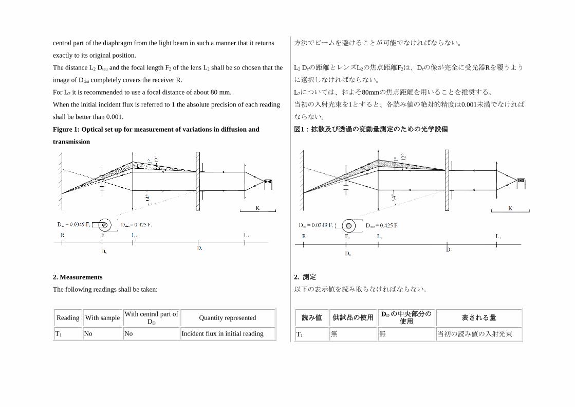
central part of the diaphragm from the light beam in such a manner that it returns
exactly to its original position.
The distance L2 Dtau and the focal length F2 of the lens L2 shall be so chosen that the
image of Dtau completely covers the receiver R.
For L2 it is recommended to use a focal distance of about 80 mm.
When the initial incident flux is referred to 1 the absolute precision of each reading
shall be better than 0.001.
方法でビームを避けることが可能でなければならない。
L2 Dτの距離とレンズL2の焦点距離F2は、Dτの像が完全に受光器Rを覆うよう
に選択しなければならない。
L2については、およそ80mmの焦点距離を用いることを推奨する。
当初の入射光束を1とすると、各読み値の絶対的精度は0.001未満でなければ
ならない。
Figure 1: Optical set up for measurement of variations in diffusion and
transmission
図1:拡散及び透過の変動量測定のための光学設備
2. Measurements
The following readings shall be taken:
2. 測定
以下の表示値を読み取らなければならない。
Reading With sample With central part of
DD Quantity represented
T1 No No Incident flux in initial reading
読み値 供試品の使用 DDの中央部分の
使用 表される量
T1 無 無 当初の読み値の入射光束
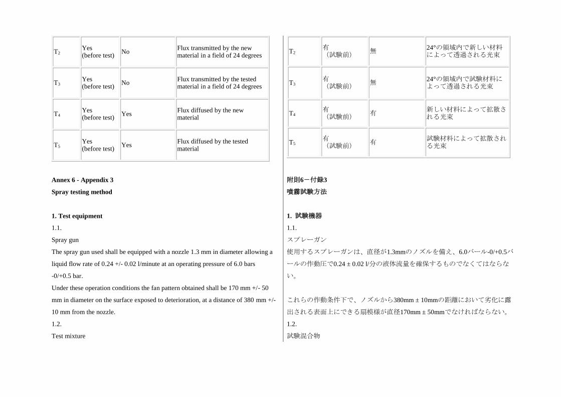
T2 Yes (before test)
No Flux transmitted by the new material in a field of 24 degrees
T3 Yes (before test)
No Flux transmitted by the tested material in a field of 24 degrees
T4 Yes (before test)
Yes Flux diffused by the new material
T5 Yes (before test)
Yes Flux diffused by the tested material
T2 有 (試験前)
無 24°の領域内で新しい材料によって透過される光束
T3 有 (試験前)
無 24°の領域内で試験材料によって透過される光束
T4 有 (試験前)
有 新しい材料によって拡散される光束
T5 有 (試験前)
有 試験材料によって拡散される光束
Annex 6 - Appendix 3
Spray testing method
附則6-付録3
噴霧試験方法
1. Test equipment 1. 試験機器
1.1.
Spray gun
The spray gun used shall be equipped with a nozzle 1.3 mm in diameter allowing a
liquid flow rate of 0.24 +/- 0.02 l/minute at an operating pressure of 6.0 bars
-0/+0.5 bar.
Under these operation conditions the fan pattern obtained shall be 170 mm +/- 50
mm in diameter on the surface exposed to deterioration, at a distance of 380 mm +/-
10 mm from the nozzle.
1.1.
スプレーガン
使用するスプレーガンは、直径が1.3mmのノズルを備え、6.0バール-0/+0.5バ
ールの作動圧で0.24 ± 0.02 l/分の液体流量を確保するものでなくてはならな
い。
これらの作動条件下で、ノズルから380mm ± 10mmの距離において劣化に露
出される表面上にできる扇模様が直径170mm ± 50mmでなければならない。
1.2.
Test mixture
1.2.
試験混合物
The test mixture shall be composed of:
Silica sand of hardness 7 on the Mohr scale, with a grain size between 0 and 0.2 mm
and an almost normal distribution, with an angular factor of 1.8 to 2;
Water of hardness not exceeding 205 g/m3 for a mixture comprising 25 g of sand per
litre of water.
試験混合物は、以下の成分で構成されなければならない。
モース硬度が7で、粒子サイズが0から0.2mmで、ほぼ正規分布した珪砂であ
って、角度係数が1.8から2のもの。
硬度が205g/m3以下の水を用いて、水1リットルあたり25gの砂が入った混合物
を作成する。
2. Test
The outer surface of the lamp lenses shall be subjected once or more than once to the
action of the sand jet produced as described above. The jet shall be sprayed almost
perpendicular to the surface to be tested.
The deterioration shall be checked by means of one or more samples of glass placed
as a reference near the lenses to be tested. The mixture shall be sprayed until the
variation in the diffusion of light on the sample or samples measured by the method
described in Appendix 2, is such that: delta d = (T5 - T4)/ T2 =0.0250 +/- 0.0025.
Several reference samples may be used to check that the whole surface to be tested
has deteriorated homogeneously.
2. 試験
灯火のレンズの外面に、上記の通り発生させた砂を1回以上噴射しなければな
らない。噴射は、試験される表面にほぼ垂直に行わなければならない。
一つ以上のガラス材料の供試品を試験するレンズの近くに基準として置き、
劣化を確認しなければならない。混合物は、付録2に記述されている方法で測
定した供試品の光の拡散の変動量がΔd = (T5 - T4)/ T2 = 0.0250 ± 0.0025となる
まで噴霧しなければならない。
試験表面全体が均質に劣化したかを確認するために複数の基準供試品を使用
することができる。
Annex 6 - Appendix 4
Adhesive tape adherence test
附則6-付録4
接着テープによる接着試験
1. Purpose
This method allows to determine under standard conditions the linear force of
adhesion of an adhesive tape to a glass plate.
1. 目的
この方法により、標準条件において、ガラス板に対する接着テープの線形接
着力を決定することができる。
2. Principle 2. 原理
Measurement of the force necessary to unstick an adhesive tape from a glass plate at
an angle of 90 degrees.
90°の角度でガラス板から接着テープを剥がすために必要な力を測定する。
3. Specified atmospheric conditions
The ambient conditions shall be at 23 degrees C +/- 5 degrees C and 65 +/- 15 per
cent relative humidity.
3. 規定される大気条件
周囲条件は、23℃ ± 5℃、相対湿度65 ± 15%でなければならない。
4. Test pieces
Before the test, the sample roll of adhesive tape shall be conditioned for 24 hours in
the specified atmosphere (see paragraph 3. above).
Five test pieces each 400 mm long shall be tested from each roll. These test pieces
shall be taken from the roll after the first three turns were discarded.
4. 試験片
試験の前に、接着テープの供試ロールを規定された大気(上記3項参照)で24
時間にわたってコンディショニングしなければならない。
各ロールよりそれぞれ400mmの長さを持つ試験片5枚を試験しなければなら
ない。これらの試験片は、ロールの最初の3巻分を捨てた後で採取しなければ
ならない。
5. Procedure
The test shall be performed under the ambient conditions specified in paragraph 3.
Take the five test pieces while unrolling the tape radially at a speed of approximately
300 mm/s, then apply them within 15 seconds in the following manner:
Apply the tape to the glass plate progressively with a slight length- wise rubbing
movement of the finger, without excessive pressure, in such a manner as to leave no
air bubble between the tape and the glass plate.
Leave the assembly in the specified atmospheric conditions for 10 minutes.
Unstick about 25 mm of the test piece from the plate in a plane perpendicular to the
axis of the test piece.
Fix the plate and fold back the free end of the tape at 90 degrees. Apply force in such
5. 手順
試験は、3項に規定された周囲条件で実施しなければならない。
テープをおよそ300mm/sの速さでロールから放射状に剥がしながら試験片5枚
を採取した後、15秒以内に以下の要領でこれらの試験片を接着させる。
過度な圧力を掛けずに指をテープの長さ方向にわずかにこすり合わせること
によって、テープをガラス板に少しずつ接着させる。その際には、テープと
ガラス板の間に気泡が残らないようにする。
このアッセンブリを規定された大気条件で10分間放置する。
ガラス板から試験片の25mmほどを試験片の軸に垂直な平面に剥がす。
ガラス板を固定し、テープの自由端を90°に折り曲げる。テープとガラス板の
a manner that the separation line between the tape and the plate is perpendicular to
this force and perpendicular to the plate.
Pull to unstick at a speed of 300 mm/s +/- 30 mm/s and record the force required.
分離線が力に対し垂直且つガラス板に対し垂直になるようにして力を加え
る。
300mm/s ± 30mm/sの速さでテープを引っ張って剥がし、且つ必要になった力
の値を記録する。
6. Results
The five values obtained shall be arranged in order and the median value taken as a
result of the measurement. This value shall be expressed in Newton per centimetre of
width of the tape.
6. 結果
得られた5つの値を順番に並べ、その中央値を測定結果として扱わなければな
らない。この値は、テープの幅1センチメートルあたりのニュートン単位で表
記しなければならない。
Annex 7
Minimum requirements for sampling by an inspector
附則7
検査官による抜取検査の最小要件
1. General 1. 一般要件
1.1.
The conformity requirements shall be considered satisfied from a mechanical and a
geometrical standpoint, if the differences do not exceed inevitable manufacturing
deviations within the requirements of this Regulation. This condition also applies to
colour.
1.1.
本規則の要件の範囲内で必然的な製造上の偏差を超えない場合には、適合性
要件が機械的及び幾何学的な観点から適合されたものとみなす。この条件
は、色度要件にも適用する。
1.2.
With respect to photometric performances, the conformity of mass- produced
systems shall not be contested if, when testing photometric performances of any
system chosen at random and equipped with a light source energized, and if
applicable corrected, as prescribed in paragraphs 1. and 2. of Annex 9 to this
1.2.
配光性能に関しては、無作為に抽出された光源を装備したシステムに電圧を
印加し配光性能の測定を行い、必要であれば本規則の附則9の1項及び2項に規
定した通り適宜補正した際に、以下に適合すれば、量産されたシステムの適
合性について疑義が生じないものとする。
Regulation:
1.2.1.
No value deviates unfavourably by more than 20 per cent from the value prescribed
in this Regulation;
1.2.1.
いずれの値も、本規則に規定されている値と比較して不利な方向に20%を超
える偏差を生じないこと。
1.2.1.1.
For the following values of the passing beam and its modes, the maximum
unfavourable deviation may be respectively:
(a) Maximum values at point B50L 170 cd equivalent 20 per cent and 255 cd
equivalent 30 per cent;
(b) Maximum values at zone III and segment BLL: 255 cd equivalent 20 per cent and
380 cd equivalent 30 per cent;
(c) Maximum values at segments E, F1, F2 and F3: 170 cd equivalent 20 per cent
and 255 cd equivalent 30 per cent;
(d) Minimum values at BR, P, at the groups S 50 + S 50LL + S 50RR and S 100 + S
100LL + S 100RR, and those required by footnote 4 of Table 1 in Annex 3 of this
Regulation (B50L, BR, BRR, BLL): half of the required value equivalent 20 per cent
and three quarter of the required value equivalent 30 per cent.
1.2.1.1.
以下に記載するすれ違い用ビーム及びその配光形態の値については、最も不
利な偏差はそれぞれ下記の通りにすることができる。
(a) ポイントB50Lにおける最大値:20%相当の170cd及び30%相当の255cd
(b) ゾーンIII及び線分BLLにおける最大値:20%相当の255cd及び30%相当の
380cd
(c) セグメントE、F1、F2及びF3における最大値:20%相当の170cd及び30%
相当の255cd
(d) BR、P、グループS 50 + S 50LL + S 50RR及びS 100 + S 100LL + S 100RRに
おける最小値、並びに本規則、附則3の表1の脚注4で要求されている最小値
(B50L、BR、BRR、BLL):20%相当の要求値の半分及び30%相当の要求値
の4分の3
1.2.1.2.
For the driving beam, HV being situated within the isolux 0.75 Imax, a tolerance of
+20 per cent for maximum values and -20 per cent for minimum values is observed
for the photometric values at any measuring point specified in paragraph 6.3.2. of
this Regulation.
1.2.2.
If the results of the test described above do not meet the requirements, the alignment
of the system may be changed, provided that the axis of the beam is not displaced
1.2.1.2.
主走行ビームにおいて、HVが0.75 Imaxの等照度曲線の範囲内にあるときに、
本規則の6.3.2項に規定されている各測定点の配光測定値において、最大値に
つき+20%、最小値につき-20%の公差が守られること。
1.2.2.
上記試験の結果が要件を満たさない場合、システムの照準調整を変更するこ
とができる。但し、ビームの軸は、横方向には右左に0.5°を超えて、上下方
laterally by more than 0.5 degree to the right or left and not by more than 0.2 degree
up and down. These provisions do not apply to lighting units as indicated under
paragraph 6.3.1.1. of this Regulation.
向には0.2°を超えて移動させない。上記の規定は、本規則の6.3.1.1項に記載さ
れている灯火ユニットには適用しない。
1.2.3.
If the results of the tests described above do not meet the requirements, tests shall be
repeated using another standard (etalon) light source and/or another supply and
operating device.
1.2.3.
上記試験の結果が要件を満たさない場合、別の標準(エタロン)光源及び/
又は別の給電及び操作装置を用いて試験を繰り返さなければならない。
1.2.4.
Systems with apparent defects are disregarded.
1.2.4.
明らかな瑕疵があるシステムは対象外とする。
1.2.5.
The reference mark is disregarded.
1.2.5.
基準マークは対象外とする。
2. First sampling
In the first sampling four systems are selected at random. The first sample of two is
marked A, the second sample of two is marked B.
2. 第一次抜取検査
第一次抜取検査では、4個のシステムを無作為に選択する。最初の供試品とな
る2個をAと表示し、2回目の供試品となる2個をBと表示する。
2.1.
The conformity is not contested
2.1.
適合性について疑義のない場合
2.1.1.
Following the sampling procedure shown in Figure 1 of this annex the conformity of
mass-produced systems shall not be contested if the deviations of the measured
values of the systems in the unfavourable directions are:
2.1.1.1.
Sample A
A1:
one system: 0 per cent
2.1.1.
本附則の図1に示す抜取検査手順の後で、システムの実測値の不利な方向への
偏差が以下に該当する場合には、量産されたシステムの適合性について疑義
が生じないものとする。
2.1.1.1.
供試品A
A1:
システム1個 0%
one system: not more than 20 per cent
A2:
both systems: more than 0 per cent
but not more than 20 per cent
Go to sample B
2.1.1.2.
Sample B
B1:
both systems: 0 per cent
システム1個 20%以下
A2:
両システム 0%を超える
但し、20%以下
供試品Bに進む
2.1.1.2.
供試品B
B1:
両システム 0%
2.1.2.
or if the conditions of paragraph 1.2.2. for sample A are fulfilled.
2.1.2.
又は、供試品Aについて1.2.2項の条件が満たされたとき
2.2.
The conformity is contested
2.2.
適合性について疑義のある場合
2.2.1.
Following the sampling procedure shown in Figure 1 of this annex the conformity of
mass-produced systems shall be contested and the manufacturer requested to make
his production meet the requirements (alignment) if the deviations of the measured
values of the systems are:
2.2.1.1.
Sample A
A3:
one system: not more than 20 per cent
one system: more than 20 per cent
but not more than 30 per cent
2.2.1.2.
2.2.1.
本附則の図1に示す抜取検査手順の後で、システムの実測値の偏差が以下に該
当する場合、量産されたシステムの適合性について疑義のあるものとし、車
両メーカー等は生産を要件に適合させること(調整)を要求されなければな
らない。
2.2.1.1.
供試品A
A3:
システム1個 20%以下
システム1個 20%を超える
但し、30%以下
2.2.1.2.
Sample B
B2: in the case of A2
one system: more than 0 per cent
but not more than 20 per cent
one system: not more than 20 per cent
B3: in the case of A2
one system: 0 per cent
one system: more than 20 per cent
but not more than 30 per cent
供試品B
B2:A2の場合
システム1個 0%を超える
但し、 20%以下
システム1個 20%以下
B3:A2の場合
システム1個 0%
システム1個 20%を超える
但し、30%以下
2.2.2.
or if the conditions of paragraph 1.2.2. for sample A are not fulfilled.
2.2.2.
又は、供試品Aについて1.2.2項の条件が満たされないとき
2.3.
Approval withdrawn
Conformity shall be contested and paragraph 10. applied if, following the sampling
procedure shown in Figure 1 of this annex, the deviations of the measured values of
the systems are:
2.3.1.
Sample A
A4:
one system: not more than 20 per cent
one system: more than 30 per cent
A5:
Both systems: more than 20 per cent
2.3.2.
Sample B
2.3.
認可取り消し
本附則の図1に示す抜取検査手順の後で、システムの実測値の偏差が以下に該
当する場合、適合性について疑義があるものとし、10項を適用しなければな
らない。
2.3.1.
供試品A
A4:
システム1個 20%以下
システム1個 30%を超える
A5:
両システム 20%を超える
2.3.2.
供試品B

B4: in the case of A2
one system: more than 0 per cent
but not more than 20 per cent
one system: more than 20 per cent
B5: in the case of A2
both systems: more than 20 per cent
B6: in the case of A2
one system: 0 per cent
one system: more than 30 per cent
2.3.3.
or if the conditions of paragraph 1.2.2. for samples A and B are not fulfilled.
B4:A2の場合
システム1個 0%を超える
但し、20%以下
システム1個 20%を超える
B5:A2の場合
両システム 20%を超える
B6:A2の場合
システム1個 0%
システム1個 30%を超える
2.3.3.
又は、供試品A及びBについて1.2.2項の条件が満たされないとき
3. Repeated sampling
In the case of A3, B2, B3 a repeated sampling, third sample C of two systems and
fourth sample D of two systems, selected from stock manufactured after alignment,
is necessary within two months' time after the notification.
3. 反復抜取検査
A3、B2、B3の場合、通知から2ヶ月以内に、反復抜取検査として、2個のシ
ステムからなる3回目の供試品C及び2個のシステムからなる4回目の供試品D
を調整実施後に製造された在庫品より選択することが必要である。
3.1.
The conformity is not contested
3.1.
適合性について疑義のない場合
3.1.1.
Following the sampling procedure shown in Figure 1 of this annex the conformity of
mass-produced shall not be contested if the deviations of the measured values of the
systems are:
3.1.1.
本附則の図1に示す抜取検査手順の後で、システムの実測値の偏差が以下に該
当する場合、量産されたシステムの適合性について疑義がないものとする。
3.1.1.1.
Sample C
C1:
3.1.1.1.
供試品C
C1:
one system: 0 per cent
one system: not more than 20 per cent
C2:
both systems: more than 0 per cent
but not more than 20 per cent
Go to sample D
システム1個 0%
システム1個 20%以下
C2:
両システム 0%を超える
但し、20%以下
供試品Dに進む
3.1.1.2.
Sample D
D1: in the case of C2
both systems: 0 per cent
3.1.1.2.
供試品D
D1:C2の場合
両システム 0%
3.1.2.
or if the conditions of paragraph 1.2.2. for sample C are fulfilled.
3.1.2.
又は、供試品Cについて1.2.2項の条件が満たされたとき
3.2.
The conformity is contested
3.2.
適合性について疑義のある場合
3.2.1.
Following the sampling procedure shown in Figure 1 of this annex the conformity of
mass-produced systems shall be contested and the manufacturer requested to make
his production meet the requirements (alignment) if the deviations of the measured
values of the systems are:
3.2.1.
本附則の図1に示す抜取検査手順の後で、システムの実測値の偏差が以下に該
当する場合、量産されたシステムの適合性について疑義のあるものとし、車
両メーカー等は生産を要件に適合させること(調整)を要求されなければな
らない。
3.2.1.1.
Sample D
D2: in the case of C2
one system: more than 0 per cent
but not more than 20 per cent
one system: not more than 20 per cent
3.2.1.1.
供試品D
D2:C2の場合
システム1個 0%を超える
但し、20%以下
システム1個 20%以下
3.2.1.2.
or if the conditions of paragraph 1.2.2 for sample C are not fulfilled.
3.2.1.2.
又は、供試品Cについて1.2.2項の条件が満たされないとき
3.3.
Approval withdrawn
Conformity shall be contested and paragraph 10. applied if, following the sampling
procedure shown in Figure 1 of this annex, the deviations of the measured values of
the systems are:
3.3.1.
Sample C
C3:
one system: not more than 20 per cent
one system: more than 20 per cent
C4:
both systems: more than 20 per cent
3.3.2.
Sample D
D3: in the case of C2
one system: 0 per cent
or more than 0 per cent
one system: more than 20 per cent
3.3.3.
or if the conditions of paragraph 1.2.2. for samples C and D are not fulfilled.
3.3.
認可取り消し
本附則の図1に示す抜取検査手順の後で、システムの実測値の偏差が以下に該
当する場合、適合性について疑義のあるものとし、10項を適用しなければな
らない。
3.3.1.
供試品C
C3:
システム1個 20%以下
システム1個 20%を超える
C4:
両システム 20%を超える
3.3.2.
供試品D
D3:C2の場合
システム1個 0%
又は、0%を超える
システム1個 20%を超える
3.3.3.
又は、供試品C及びDについて1.2.2項の条件が満たされないとき
4. Change of the vertical position of the cut-off line for passing beam
With respect to the verification of the change in vertical position of the cut-off line
4. すれ違い用ビームのカットオフラインの垂直位置の変化
熱による影響を受けたすれ違い用ビームのカットオフラインの垂直位置の変
for passing beam under the influence of heat, the following procedure shall be
applied:
One of the systems of sample A after sampling procedure in Figure 1 of this annex
shall be tested according to the procedure described in paragraph 2.1. of Annex 4
after being subjected three consecutive times to the cycle described in paragraph
2.2.2. of Annex 4.
The system shall be considered as acceptable if delta r does not exceed 1.5 mrad
upwards and does not exceed 2.5 mrad downwards.
If this value exceeds 1.5 mrad but is not more than 2.0 mrad upwards or exceeds 2.5
mrad but is not more than 3.0 mrad downwards, the second system of sample A shall
be subjected to the test after which the mean of the absolute values recorded on both
samples shall not exceed 1.5 mrad upwards and shall not exceed 2.5 mrad
downwards.
However, if this value of 1.5 mrad upwards and 2.5 mrad downwards on sample A is
not complied with, the two systems of sample B shall be subjected to the same
procedure and the value of r for each of them shall not exceed 1.5 mrad upwards
and shall not exceed 2.5 mrad downwards.
化の確認に関し、以下の手順を適用しなければならない。
本附則の図1の抜取検査手順の後で供試品Aのシステムのうち1個に附則4の
2.2.2項に定めるサイクルを3回連続で実施した後で附則4の2.1項に定める手順
に従って試験を行わなければならない。
システムは、Δrが上向きで1.5mradを超えず、かつ下向きで2.5mardを超えな
い場合において、合格とみなすものとする。
この値が上向きで1.5mradを超えるが、2.0mrad以下である場合、又は、下向
きで2.5mardを超えるが、3.0mard以下である場合においては、供試品Aの2回
目のシステムで試験を実施しするものとし、その結果、両供試品で記録され
た絶対値の平均が上向きで1.5mradを超えないものとし、かつ下向きで
2.5mardを超えないものとする。
但し、供試品Aで上記の1.5mradの値が満たされない場合、供試品Bの二つの
システムに関して同じ手順で試験を行い、これらのシステムのいずれでもΔr
の値が上向きで1.5mradを超えず、かつ下向きで2.5mardを超えないものとす
る。
Figure 1
Note: "device" in this figure means "system"
図1
注:この図中の「装置」は「システム」をいう。
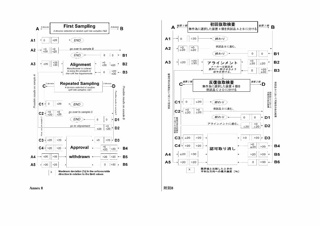
Annex 8 附則8
初回抜取検査 無作為に選択した装置 4個を供試品 A と Bに分ける
供試品 Bに進む。
供試品 Dに進む。 供試品
Aにおいて可能性のある結果
供試品
Bにおいて可能性のある結果
供試品
Dにおいて
可能性のある結果
供試品
Dにおいて
可能性のある結果
反復抜取検査 無作為に選択した装置 4個を 供試品 C と Dに分ける
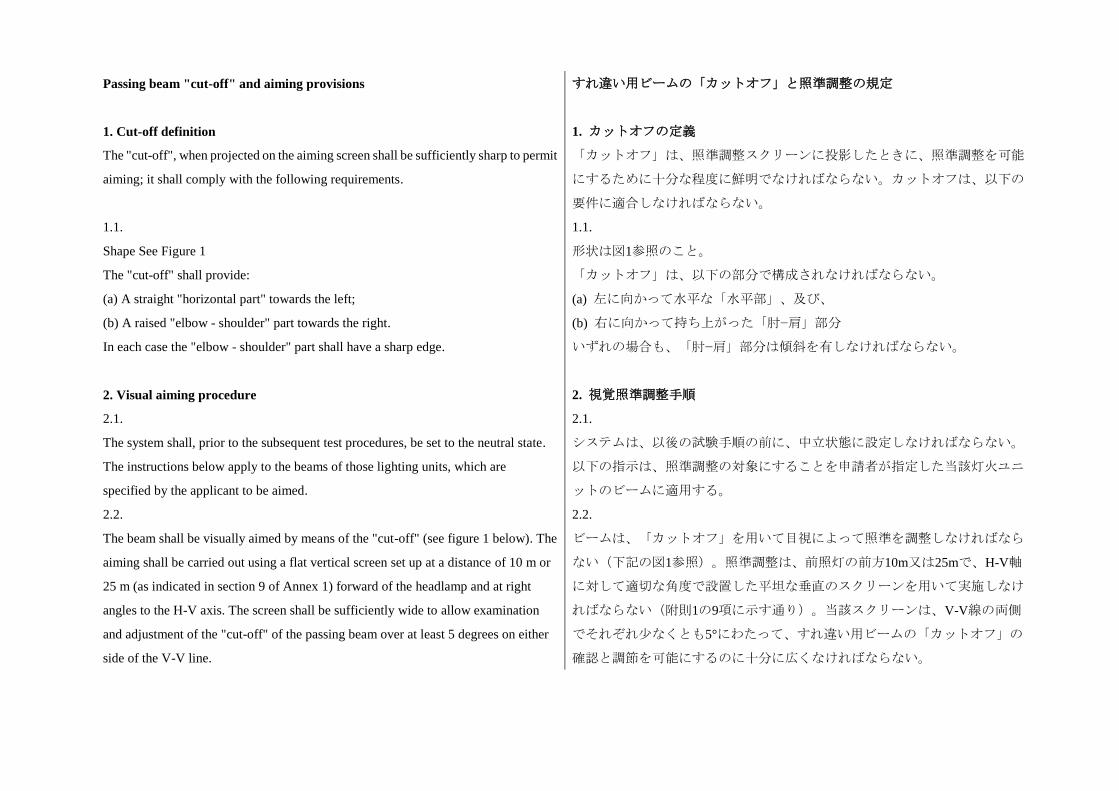
Passing beam "cut-off" and aiming provisions すれ違い用ビームの「カットオフ」と照準調整の規定
1. Cut-off definition
The "cut-off", when projected on the aiming screen shall be sufficiently sharp to permit
aiming; it shall comply with the following requirements.
1.1.
Shape See Figure 1
The "cut-off" shall provide:
(a) A straight "horizontal part" towards the left;
(b) A raised "elbow - shoulder" part towards the right.
In each case the "elbow - shoulder" part shall have a sharp edge.
1. カットオフの定義
「カットオフ」は、照準調整スクリーンに投影したときに、照準調整を可能
にするために十分な程度に鮮明でなければならない。カットオフは、以下の
要件に適合しなければならない。
1.1.
形状は図1参照のこと。
「カットオフ」は、以下の部分で構成されなければならない。
(a) 左に向かって水平な「水平部」、及び、
(b) 右に向かって持ち上がった「肘−肩」部分
いずれの場合も、「肘−肩」部分は傾斜を有しなければならない。
2. Visual aiming procedure 2. 視覚照準調整手順
2.1.
The system shall, prior to the subsequent test procedures, be set to the neutral state.
The instructions below apply to the beams of those lighting units, which are
specified by the applicant to be aimed.
2.1.
システムは、以後の試験手順の前に、中立状態に設定しなければならない。
以下の指示は、照準調整の対象にすることを申請者が指定した当該灯火ユニ
ットのビームに適用する。
2.2.
The beam shall be visually aimed by means of the "cut-off" (see figure 1 below). The
aiming shall be carried out using a flat vertical screen set up at a distance of 10 m or
25 m (as indicated in section 9 of Annex 1) forward of the headlamp and at right
angles to the H-V axis. The screen shall be sufficiently wide to allow examination
and adjustment of the "cut-off" of the passing beam over at least 5 degrees on either
side of the V-V line.
2.2.
ビームは、「カットオフ」を用いて目視によって照準を調整しなければなら
ない(下記の図1参照)。照準調整は、前照灯の前方10m又は25mで、H-V軸
に対して適切な角度で設置した平坦な垂直のスクリーンを用いて実施しなけ
ればならない(附則1の9項に示す通り)。当該スクリーンは、V-V線の両側
でそれぞれ少なくとも5°にわたって、すれ違い用ビームの「カットオフ」の
確認と調節を可能にするのに十分に広くなければならない。
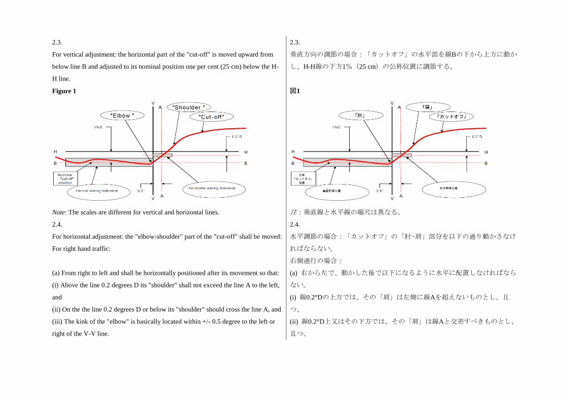
2.3.
For vertical adjustment: the horizontal part of the "cut-off" is moved upward from
below line B and adjusted to its nominal position one per cent (25 cm) below the H-
H line.
2.3.
垂直方向の調節の場合:「カットオフ」の水平部を線Bの下から上方に動か
し、H-H線の下方1%(25 cm)の公称位置に調節する。
Figure 1
Note: The scales are different for vertical and horizontal lines.
図1
注:垂直線と水平線の縮尺は異なる。
2.4.
For horizontal adjustment: the "elbow-shoulder" part of the "cut-off" shall be moved:
For right hand traffic:
(a) From right to left and shall be horizontally positioned after its movement so that:
(i) Above the line 0.2 degrees D its "shoulder" shall not exceed the line A to the left,
and
(ii) On the the line 0.2 degrees D or below its "shoulder" should cross the line A, and
(iii) The kink of the "elbow" is basically located within +/- 0.5 degree to the left or
right of the V-V line.
2.4.
水平調節の場合:「カットオフ」の「肘−肩」部分を以下の通り動かさなけ
ればならない。
右側通行の場合:
(a) 右から左で、動かした後で以下になるように水平に配置しなければなら
ない。
(i) 線0.2°Dの上方では、その「肩」は左側に線Aを超えないものとし、且
つ、
(ii) 線0.2°D上又はその下方では、その「肩」は線Aと交差すべきものとし、
且つ、
Or
For left hand traffic:
(b) From left to right and shall be horizontally positioned after its movement so that:
(i) Above the line 0.2 degrees D its "shoulder" shall not exceed the line A to the
right, and
(ii) On the the line 0.2 degrees D or below its "shoulder" should cross the line A, and
(iii) The kink of the "elbow" is basically located within +/- 0.5 degree to the left or
right of the V-V line.
(iii) 基本的に、「肘」のエルボー点はV-V線の左又は右に±0.5°内に位置す
る。
又は
左側通行の場合:
(b) 左から右で、動かした後に以下になるように水平に配置しなければなら
ない。
(i) 線0.2°Dの上方では、その「肩」は右側に線Aを超えないものとし、且
つ、
(ii) 線0.2°D上又はその下方では、その「肩」は線Aと交差すべきものとし、
且つ、
(iii) 基本的に、「肘」のエルボー点はV-V線の左又は右に±0.5°内に位置す
る。
2.5.
Where a headlamp so aimed does not meet the requirements set out in Annex 3 its
alignment may be changed, provided that the axis of the beam is not displaced:
Horizontally, from line A by more than: 0.5 degrees to the left or 0.75 degrees to the
right;
Vertically not more than 0.25 degrees up or down from line B.
2.5.
上記の通り照準調整をした前照灯が、附則3に規定した要件を満たさない場合
は、その照準調整を変更することができる。但し、ビームの軸が下記のよう
に移動しないことを条件とする。
線Aから以下を超える水平移動:左に0.5°又は右に0.75°
線Bから上又は下に0.25°を超える垂直の移動
2.6.
If, however, vertical adjustment cannot be performed repeatedly to the required
position within the tolerances described in paragraph 2.5. above, the instrumental
method described in paragraph 3. shall be applied to test compliance with the
required minimum quality of the "cut-off" (as defined in paragraph 2.7.) and to
perform the vertical and horizontal adjustment of the beam.
2.6.
但し、上記2.5項に記載された公差内で、要求された位置まで垂直調節を繰り
返し実行できない場合は、「カットオフ」の要求される最低品質(2.7項に定
義)への適合を試験し、ビームの垂直及び水平調節を実行するために、3項に
記載した計測による方法を適用しなければならない。
2.7. 2.7.
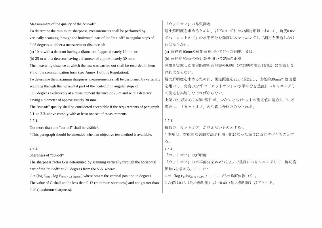
Measurement of the quality of the "cut-off"
To determine the minimum sharpness, measurements shall be performed by
vertically scanning through the horizontal part of the "cut-off" in angular steps of
0.05 degrees at either a measurement distance of:
(a) 10 m with a detector having a diameter of approximately 10 mm or
(b) 25 m with a detector having a diameter of approximately 30 mm.
The measuring distance at which the test was carried out shall be recorded in item
9.8 of the communication form (see Annex 1 of this Regulation).
To determine the maximum sharpness, measurements shall be performed by vertically
scanning through the horizontal part of the "cut-off" in angular steps of
0.05 degrees exclusively at a measurement distance of 25 m and with a detector
having a diameter of approximately 30 mm.
The "cut-off" quality shall be considered acceptable if the requirements of paragraph
2.1. to 2.3. above comply with at least one set of measurements.
2.7.1.
Not more than one "cut-off" shall be visible1.
1 This paragraph should be amended when an objective test method is available.
2.7.2.
Sharpness of "cut-off"
The sharpness factor G is determined by scanning vertically through the horizontal
part of the "cut-off" at 2.5 degrees from the V-V where:
G = (log Ebeta - log E(beta + 0.1 degrees)) where beta = the vertical position in degrees.
The value of G shall not be less than 0.13 (minimum sharpness) and not greater than
0.40 (maximum sharpness).
「カットオフ」の品質測定
最小鮮明度を求めるために、以下のいずれかの測定距離において、角度0.05°
ずつ「カットオフ」の水平部分を垂直にスキャニングして測定を実施しなけ
ればならない。
(a) 直径約10mmの検出器を用いて10mの距離、又は、
(b) 直径約30mmの検出器を用いて25mの距離
試験を実施した測定距離を通知書の9.8項(本規則の附則1参照)に記録しな
ければならない。
最大鮮明度を求めるために、測定距離を25mに限定し、直径約30mmの検出器
を用いて、角度0.05°ずつ「カットオフ」の水平部分を垂直にスキャニングし
て測定を実施しなければならない。
上記の2.1項から2.3項の要件が、少なくとも1セットの測定値に適合している
場合に、「カットオフ」の品質は合格とみなされる。
2.7.1.
複数の「カットオフ」が見えないものとする1。
1 本項は、客観的な試験方法が利用可能になった場合に改訂すべきものとす
る。
2.7.2.
「カットオフ」の鮮明度
「カットオフ」の水平部分をV-Vから2.5°で垂直にスキャニングして、鮮明度
係数Gを求める。ここで:
G=(log Eβ-log E(β + 0.1°))、ここでβ=垂直位置(°)。
Gの値は0.13(最小鮮明度)以上0.40(最大鮮明度)以下とする。
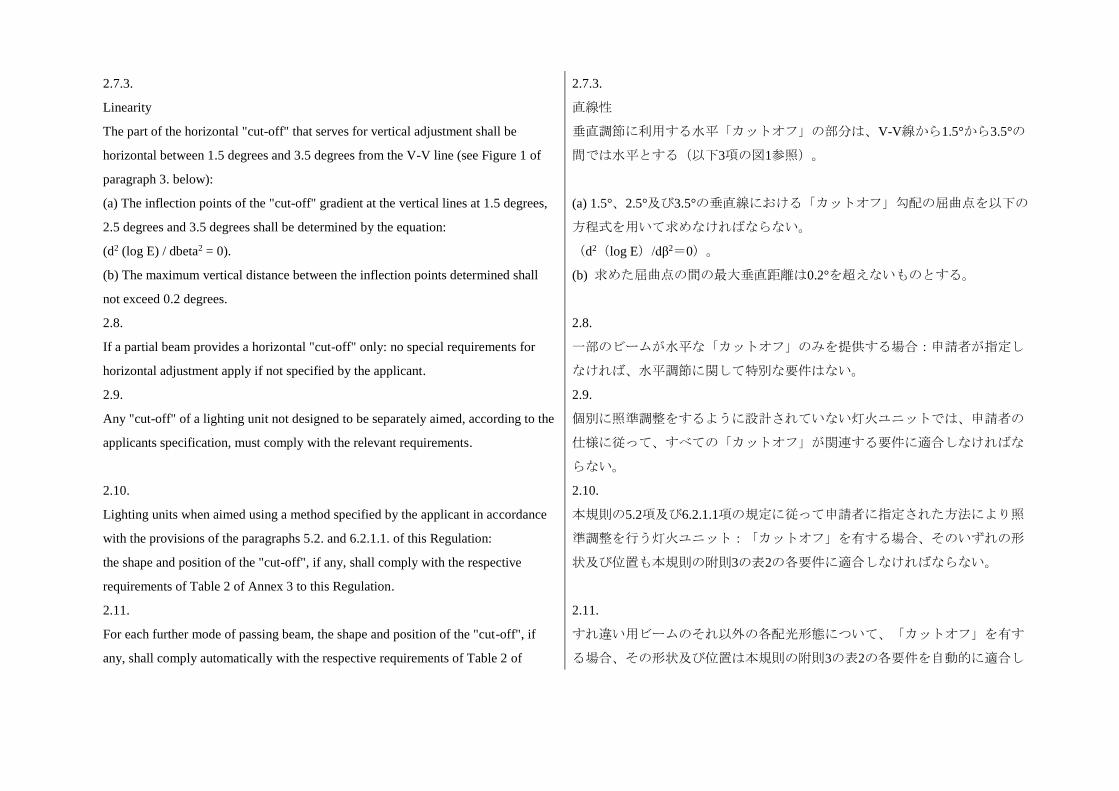
2.7.3.
Linearity
The part of the horizontal "cut-off" that serves for vertical adjustment shall be
horizontal between 1.5 degrees and 3.5 degrees from the V-V line (see Figure 1 of
paragraph 3. below):
(a) The inflection points of the "cut-off" gradient at the vertical lines at 1.5 degrees,
2.5 degrees and 3.5 degrees shall be determined by the equation:
(d2 (log E) / dbeta2 = 0).
(b) The maximum vertical distance between the inflection points determined shall
not exceed 0.2 degrees.
2.7.3.
直線性
垂直調節に利用する水平「カットオフ」の部分は、V-V線から1.5°から3.5°の
間では水平とする(以下3項の図1参照)。
(a) 1.5°、2.5°及び3.5°の垂直線における「カットオフ」勾配の屈曲点を以下の
方程式を用いて求めなければならない。
(d2(log E)/dβ2=0)。
(b) 求めた屈曲点の間の最大垂直距離は0.2°を超えないものとする。
2.8.
If a partial beam provides a horizontal "cut-off" only: no special requirements for
horizontal adjustment apply if not specified by the applicant.
2.8.
一部のビームが水平な「カットオフ」のみを提供する場合:申請者が指定し
なければ、水平調節に関して特別な要件はない。
2.9.
Any "cut-off" of a lighting unit not designed to be separately aimed, according to the
applicants specification, must comply with the relevant requirements.
2.9.
個別に照準調整をするように設計されていない灯火ユニットでは、申請者の
仕様に従って、すべての「カットオフ」が関連する要件に適合しなければな
らない。
2.10.
Lighting units when aimed using a method specified by the applicant in accordance
with the provisions of the paragraphs 5.2. and 6.2.1.1. of this Regulation:
the shape and position of the "cut-off", if any, shall comply with the respective
requirements of Table 2 of Annex 3 to this Regulation.
2.10.
本規則の5.2項及び6.2.1.1項の規定に従って申請者に指定された方法により照
準調整を行う灯火ユニット:「カットオフ」を有する場合、そのいずれの形
状及び位置も本規則の附則3の表2の各要件に適合しなければならない。
2.11.
For each further mode of passing beam, the shape and position of the "cut-off", if
any, shall comply automatically with the respective requirements of Table 2 of
2.11.
すれ違い用ビームのそれ以外の各配光形態について、「カットオフ」を有す
る場合、その形状及び位置は本規則の附則3の表2の各要件を自動的に適合し
Annex 3. to this Regulation. なければならない。
2.12.
A separate initial aiming and/or adjustment process according to the applicant's
specification, based on the provisions of paragraphs 2.1. through 2.6. above, may
apply to lighting units intended to be installed separately.
2.12.
上記2.1項から2.6項の規定に基づいた個別の初期照準調整及び/又は調節方法
は、申請者の仕様に従い、独立して取り付けられることを目的とした灯火ユ
ニットに対して適用することができる。
3. Vertical and horizontal adjustment
If the "cut-off" complies with the quality requirements of paragraph 2. of this Annex,
the beam adjustment may be performed instrumentally.
3. 垂直及び水平調節
「カットオフ」が本附則の2項の品質要件に適合している場合は、ビームの調
節を計測により実施することができる。
Figure 1: Measurement of "cut-off" quality
Note: The scales are different for vertical and horizontal lines.
図1:「カットオフ」品質の測定
注:垂直線と水平線の縮尺は異なる。
3.1.
Vertical adjustment
Moving upward from below the line B (see figure 2 below), a vertical scan is carried
out through the horizontal part of the "cut-off" at 2.5 degrees from V-V.
3.1.
垂直調節
線Bの下から上方に(下記の図2参照)動かして、V-Vから2.5°において「カ
ットオフ」の水平部分の垂直スキャンを実施する。屈曲点(ここで、d2(log
The inflection point (where d2 (log E) / dv2 = 0) is determined and positioned on the
line B situated one per cent below H-H.
E)/dv2=0)を求め、H-Hの下方1%に位置する線B上に配置する。
3.2.
Horizontal adjustment
The applicant shall specify one of the following horizontal aim methods:
(a) The "0.2 D line" method (see figure 2 below).
A single horizontal line at 0.2 degrees D shall be scanned from 5 degrees left to 5
degrees right after the lamp has been aimed vertically. The maximum gradient
"G" determined using the formula G = (log Ebeta - log E(beta + 0.1 degrees)) where beta is
the horizontal position in degrees, shall not be less than 0.08.
The inflection point found on the 0.2 D line shall be positioned on the line A.
3.2.
水平調節
申請者は、以下の水平照準調整の方法の一つを指定しなければならない。
(a) 「0.2 Dライン」法(下記の図2参照)
灯火を垂直方向に照準を合わせた後、0.2°Dにおいて1本の水平線を左5°から
右5°にスキャンしなければならない。式G=(log Eβ-log E(β + 0.1°))、(ここ
で、βは水平位置(°))を用いて求めた最大勾配「G」は0.08以上でなければ
ならない。
線0.2 D上にある屈曲点を線A上に配置しなければならない。
Figure 2: Instrumental vertical and horizontal adjustment - Horizontal line scan
method
Note: The scales are different for vertical and horizontal lines.
図2:計測による垂直及び水平調節−水平線スキャン法
注:垂直線と水平線の縮尺は異なる。
(b) The "3 line" method (see figure 3 below)
Three vertical lines shall be scanned from 2 degrees D to 2 degrees U at 1 degree R,
(b) 「3ライン」法(下記の図3参照)
灯火を垂直方向に照準を合わせた後、1°R、2°R、及び3°Rにおいて3本の垂直
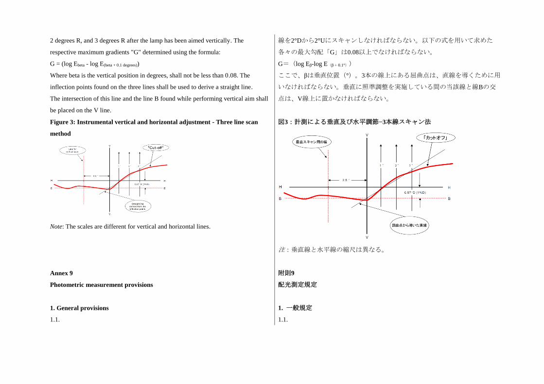
2 degrees R, and 3 degrees R after the lamp has been aimed vertically. The
respective maximum gradients "G" determined using the formula:
G = (log Ebeta - log E(beta + 0.1 degrees))
Where beta is the vertical position in degrees, shall not be less than 0.08. The
inflection points found on the three lines shall be used to derive a straight line.
The intersection of this line and the line B found while performing vertical aim shall
be placed on the V line.
線を2°Dから2°Uにスキャンしなければならない。以下の式を用いて求めた
各々の最大勾配「G」は0.08以上でなければならない。
G=(log Eβ-log E(β + 0.1°))
ここで、βは垂直位置(°)。3本の線上にある屈曲点は、直線を導くために用
いなければならない。垂直に照準調整を実施している間の当該線と線Bの交
点は、V線上に置かなければならない。
Figure 3: Instrumental vertical and horizontal adjustment - Three line scan
method
Note: The scales are different for vertical and horizontal lines.
図3:計測による垂直及び水平調節−3本線スキャン法
注:垂直線と水平線の縮尺は異なる。
Annex 9
Photometric measurement provisions
附則9
配光測定規定
1. General provisions 1. 一般規定
1.1. 1.1.
The system or part(s) thereof shall be mounted on a gonio(photo)meter system. システム又はシステムの部品は、ゴニオ(フォト)メータシステムに取り付
けなければならない。
1.2.
The luminous intensity values shall be determined by means of a photoreceptor
contained within a square of 65 m side and set up to a distance of at least 25 m
forward of the centre of reference of each lighting unit perpendicular to the
measurement axis from the origin of the gonio(photo)meter system.
1.2.
配光測定値は、一辺が65mの正方形内に収められ、且つゴニオ(フォト)メ
ータシステムの起点より、測定軸に垂直な各灯火ユニットの基準中心の前方
に少なくとも25mの距離に設置された受光器によって求められなければなら
ない。
1.3.
During photometric measurements, stray reflections should be avoided by
appropriate masking.
1.3.
配光測定中は、適当な遮蔽を行うことによって乱反射を防ぐべきものとす
る。
1.4.
The luminous intensities are measured at a nominal distance of 25 m.
1.4.
光度は、25mの公称距離で測定される。
1.5.
The angular coordinates are specified in degrees on a sphere corresponding to a
gonio(photo)meter system as defined in Regulation No. 48. (see diagram 1).
1.5.
角度座標は、協定規則第48号に定義されたゴニオ(フォト)メータシステム
に対応する球面上の度を単位として定められる(略図1参照)。
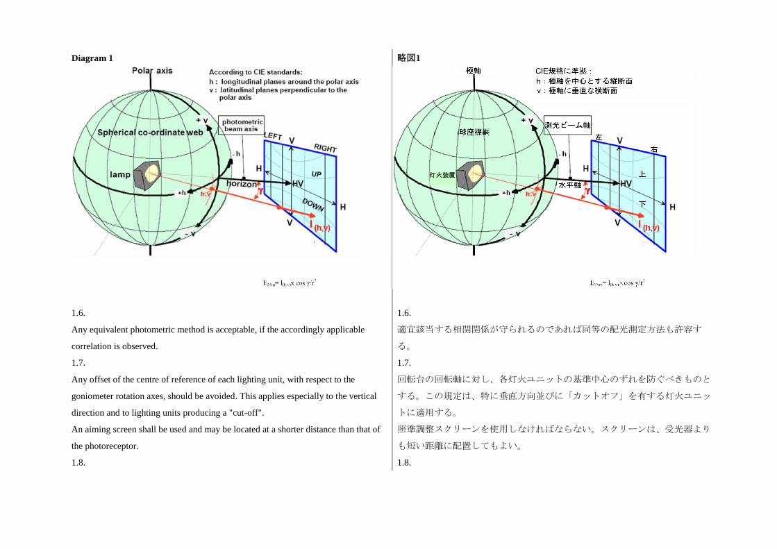
Diagram 1
略図1
1.6.
Any equivalent photometric method is acceptable, if the accordingly applicable
correlation is observed.
1.6.
適宜該当する相関関係が守られるのであれば同等の配光測定方法も許容す
る。
1.7.
Any offset of the centre of reference of each lighting unit, with respect to the
goniometer rotation axes, should be avoided. This applies especially to the vertical
direction and to lighting units producing a "cut-off".
An aiming screen shall be used and may be located at a shorter distance than that of
the photoreceptor.
1.7.
回転台の回転軸に対し、各灯火ユニットの基準中心のずれを防ぐべきものと
する。この規定は、特に垂直方向並びに「カットオフ」を有する灯火ユニッ
トに適用する。
照準調整スクリーンを使用しなければならない。スクリーンは、受光器より
も短い距離に配置してもよい。
1.8. 1.8.
灯火装置
The photometric requirements for each single measuring point (angular position) of a
lighting function or mode as specified in this Regulation apply to half of the sum of
the respective measured values from all lighting units of the system applied for this
function or mode, or, from all lighting units as indicated in the respective
requirement;
本規則に規定する灯火機能又は配光形態の個々の測定点(角度位置)につい
ての配光要件は、当該機能又は配光形態に適用されるシステムのすべての灯
火ユニット又は各要件に記載されたすべての灯火ユニットからの各実測値の
合計値の半分の値に適用する。
1.8.1.
However in those cases where a provision is specified for one side only, the division
by the factor of 2 does not apply. These cases are: paragraphs 6.2.5.2., 6.2.8.1.,
6.3.2.1.1., 6.3.2.1.2., 6.3.4.1., 6.4.6. and note 4 of Table 1 of Annex 3
1.8.1.
但し、一方の側のみについての規定が定められている事例では、2を係数とし
た除算は適用しない。これらの事例は次のとおりである:6.2.5.2項、
6.2.8.1項、6.3.2.1.1項、6.3.2.1.2項、6.3.4.1項、6.4.6項および附則3、
表1の注4。
1.9.
The lighting units of the system shall be measured individually; however,
simultaneous measurements may be performed on two or more lighting units of an
installation unit, being equipped with the same light source types with respect to
their power supply (either power controlled or not), if they are sized and situated
such, that their illuminating surfaces are completely contained in a rectangle of not
more than 300 mm in horizontal extend and not more than 150 mm vertical extend,
and, if a common centre of reference is specified by the manufacturer
1.9.
システムの灯火ユニットは、個別に測定しなければならない。但し、一つの
取り付けユニット内の二つ以上の灯火ユニットが入力電源に関して同一の光
源タイプ(電源制御付きか否かを問わない)を装備し、且つ、水平の長さが
300mm以下、垂直の長さが150mm以下の長方形内にそれぞれの照射面が完全
に収まるような寸法及び配置であり、且つ、車両メーカー等によって共通の
基準中心が指定されている場合には、これらの灯火ユニットを同時に測定す
ることができる。
1.10.
The system shall prior to the subsequent test procedures be set to the neutral state.
1.10.
システムは、以下の試験手順の前に、中立状態に設定しなければならない。
1.11.
The system or part(s) thereof shall be so aimed before starting the measurements that
the position of the "cut-off" complies with the requirements indicated in the Table 2
of Annex 3 to this Regulation. Parts of a system measured individually and having
1.11.
システム又はシステムの部品は、測定を開始する前に、「カットオフ」の位
置が本規則の附則3の表2に記載されている要件に適合するように照準調整を
行わなければならない。個別に測定されるシステムの部品で、「カットオ
no "cut-off" shall be installed on the goniometer under the conditions (mounting
position) specified by the applicant.
フ」がないものは、申請者が指定する条件(取り付け位置)で回転台に取り
付けなければならない。
2. Measurement conditions with respect to light sources 2. 光源に関する測定条件
2.1.
In the case of replaceable filament lamps operated directly under vehicle voltage
system conditions:
The system or parts thereof shall be checked by means of an uncoloured standard
(etalon) light source and/or another supply and operating device. Filament lamp(s)
designed for a rated voltage of 12 V. During checking of the system or part of, the
voltage at the terminals of the filament lamp(s) shall be regulated so as to obtain the
reference luminous flux 13.2 volts as indicated at the relevant data sheet of
Regulation No. 37.
For the measurements, the flux of this filament lamp may differ from the reference
luminous flux at 13.2 V specified in Regulation No. 37. In this case, the luminous
intensity shall be corrected accordingly by the individual factor of the standard
(etalon) filament lamp (F = phi obj. / phi (Voltage)).
The system or parts thereof shall be considered acceptable if the requirements of
paragraph 6. of this Regulation are met with at least one standard (etalon) filament
lamp, which may be submitted with the system.
2.1.
車両の電圧システムの条件によって直接に作動する交換式フィラメント電球
の場合
システム又はその部品は、定格電圧12V向けに設計された無色の標準(エタ
ロン)フィラメント電球を用いて確認しなければならない。システム又はシ
ステムの部品の確認中、フィラメント電球の端子での電圧は、協定規則第37
号の該当するデータシートに記載された13.2Vにおける基準光束が得られるよ
うに調整しなければならない。
測定については、このフィラメント電球の光束値は、協定規則第37号に規定
された13.2Vにおける基準光束値と異なっていてもよい。この場合、標準(エ
タロン)フィラメント電球の個別の係数(F = Φ obj./Φ(電圧))によって、
適宜、光度を補正しなければならない。
システム又はその部品は、本規則の6項の要件が少なくとも1個の(システム
と共に提出することができる)標準(エタロン)フィラメント電球で満たさ
れた場合に合格したものとみなす。
2.2.
In the case of a replaceable gas-discharge light source:
The voltage applied at the terminals of the ballast(s) or at the terminals of the light
source(s) in case the ballast is integrated with the light source, is 13.2 V +/-0.1 for 12
2.2.
交換式ガス放電光源の場合:
バラストの端子、又はバラストが光源と一体である場合は光源の端子に掛か
る電圧は、12Vのシステムの場合は13.2V±0.1である。
V systems.
The system or parts thereof using a replaceable gas-discharge light source shall
comply with the photometric requirements set out in the relevant paragraphs of this
Regulation with at least one standard (etalon) light source, which has been aged
during at least 15 cycles, as specified in Regulation No. 99. The luminous flux of this
gas-discharge light source may differ from the objective luminous flux specified in
Regulation No. 99.
In this case, the measured photometric values shall be corrected accordingly.
交換式ガス放電光源を用いたシステム又はシステムの部分は、協定規則第99
号に規定されている通り最低15回のサイクルで点灯させた少なくとも1個の標
準(エタロン)光源により、本規則の該当する項に規定された配光要件に適
合しなければならない。このガス放電光源の光束値は、協定規則第99号に規
定された目標光束値とは異なっていてもよい。
この場合、実測した配光測定値を適宜補正しなければならない。
2.3.
In the case of a non-replaceable light source operating directly under vehicle voltage
system conditions:
All measurements on lamps equipped with non-replaceable light sources (filament
lamps and other) shall be made at 6.3 V, 13.2 V or 28.0 V, or at a voltage as
specified by the applicant with respect to any other vehicle voltage system.
2.3.
車両の電圧システムの条件によって直接に作動する非交換式光源の場合
非交換式光源(フィラメント電球及びその他)を装備した灯火の測定はいず
れも、6.3V、13.2V若しくは28.0V、又はその他の車両電圧システムに関して
申請者が指定した電圧で実施しなければならない。
2.4.
In the case of a light source, replaceable or non-replaceable, which is operated
independently from vehicle supply voltage and fully controlled by the system, or in
the case of a light source supplied by a special power supply, the test voltage as
specified in paragraph 2.3. above shall be applied to the input terminals of that
system/power supply. The test laboratory may require from the manufacturer this
special power supply needed to supply the light sources.
2.4.
車両の供給電圧と独立して作動し、システムによって完全に制御される光源
(交換式光源又は非交換式光源)の場合、又は特殊な電源によって給電され
る光源の場合は、上記2.3項に規定された試験電圧を当該システム/電源の入
力端子に印加しなければならない。試験機関は、光源に給電するために必要
な上記の特殊電源を車両メーカー等に要求することができる。
2.5.
LED module(s) shall be measured at 6.3 V, 13.2 V or 28.0 V respectively, if not
otherwise specified within this Regulation. LED module(s) operated by an electronic
light source control gear, shall be measured as specified by the applicant.
2.5.
LEDモジュールは、本規則に別段の規定がない限り、6.3V、13.2V又は28.0V
の各電圧にて測定しなければならない。電子式光源制御装置により作動させ
るLEDモジュールは、申請者が指定する通りに測定しなければならない。
3. Measurement conditions with respect to bending modes
3.1.
In the case of a system or part(s) thereof, which provide a bending mode, the
requirements of paragraphs 6.2. (passing beam), and/or 6.3. (driving beam) of this
Regulation apply for all states, corresponding to the turn radius of the vehicle. For
verification with respect to the passing beam and the driving beam the following
procedure shall be used:
3.1.1.
The system shall be tested in the neutral state (central/straight), and, in addition in
the state(s) corresponding to the smallest turn radius of the vehicle in both directions
using the signal generator, if applicable.
3.1.1.1.
Compliance with the requirements of paragraphs 6.2.5.2. and 6.2.5.4.1.of this
Regulation shall be checked for both Category 1 and Category 2 bending modes
without additional horizontal re-aim.
3.1.1.2.
Compliance with the requirements of paragraphs 6.2.5.1. and 6.3. of this Regulation,
whichever applies, shall be checked:
(a) In case of a category 2 bending mode: without additional horizontal re-aim;
(b) In case of a category 1 or a driving beam bending mode: after having horizontally
re-aimed the relevant installation unit (by means of the goniometer for example) in
the corresponding opposite direction.
3.1.2.
3. 曲線道路用配光形態に関する測定条件
3.1.
曲線道路用配光形態を提供するシステム又はその部品の場合、本規則の6.2項
(すれ違い用ビーム)及び/又は6.3項(主走行ビーム)の要件は、車両の回
転半径に対応するすべての状態に適用する。すれ違い用ビーム及び主走行ビ
ームに関する確認には、以下の手順を用いなければならない。
3.1.1.
システムは、中立状態(中央/直線)で試験することに加えて、信号発生器
を有する場合にはそれを用いて、両方向の車両の最小回転半径に対応する状
態で試験しなければならない。
3.1.1.1.
本規則の6.2.5.2項および6.2.5.4.1項の要件への適合は、水平方向の再照準を追
加実施することなしに種類1及び種類2の曲線道路用配光形態の両方について
確認しなければならない。。
3.1.1.2.
本規則の6.2.5.1項及び6.3項の要件への適合は、いずれが適用される場合で
も、以下の通り確認しなければならない。
(a) 種類2の曲線道路用配光形態の場合:水平方向の再照準を追加実施せずに
確認する。
(b) 種類1又は主走行ビームの曲線道路用配光形態の場合:関連する取り付け
ユニットを(例えば回転台を使って)対応する方向とは反対の方向に水平方
向の再照準を行った後で確認する。
3.1.2.
When testing a category 1 or category 2 bending mode, for a turn radius of the
vehicle other than specified in paragraph 3.1.1. above: it shall be observed whether
the light distribution is substantially uniform and no undue glare occurs. If this can
not be confirmed the compliance with the requirement laid down in Table 1 of
Annex 3 to this Regulation shall be checked.
上記3.1.1項に規定した以外の車両の回転半径について、種類1又は種類2の曲
線道路用配光形態を試験する場合、光の分布が実質的に均等で、過度のグレ
アが生じないことを観察しなければならない。このことが確認できない場合
は、本規則の附則3の表1に規定した要件への適合を確認しなければならな
い。
Annex 10
Description forms
Maximum format: A4 (210 x 297 mm)
附則10
説明書式
最大A4判(210 × 297mm)
Adaptive front-lighting system description form No. 1
AFS control signals relevant to the lighting functions, and modes of functions
provided by the system
配光可変型前照灯システムの説明書式No. 1
システムによって提供される灯火機能及び機能の配光形態に関係するAFS制
御信号
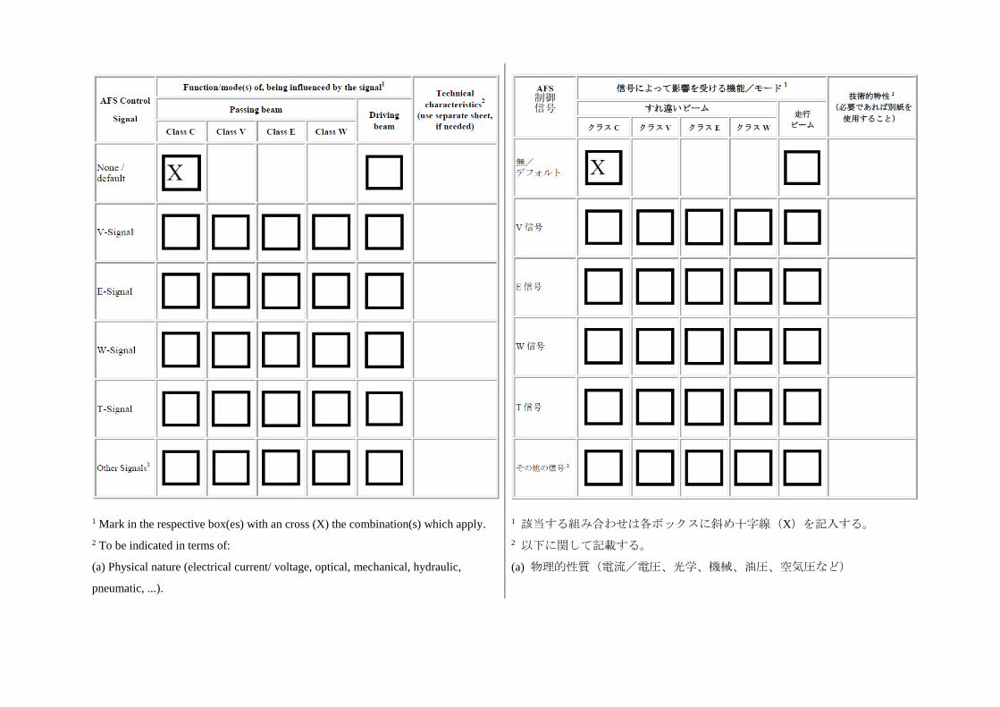
1 Mark in the respective box(es) with an cross (X) the combination(s) which apply.
2 To be indicated in terms of:
(a) Physical nature (electrical current/ voltage, optical, mechanical, hydraulic,
pneumatic, ...).
1 該当する組み合わせは各ボックスに斜め十字線(X)を記入する。
2 以下に関して記載する。
(a) 物理的性質(電流/電圧、光学、機械、油圧、空気圧など)
制御 信号
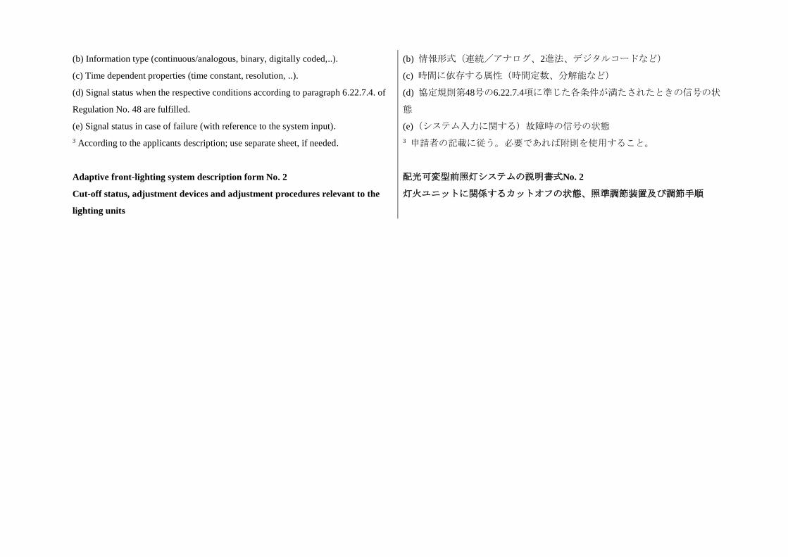
(b) Information type (continuous/analogous, binary, digitally coded,..).
(c) Time dependent properties (time constant, resolution, ..).
(d) Signal status when the respective conditions according to paragraph 6.22.7.4. of
Regulation No. 48 are fulfilled.
(e) Signal status in case of failure (with reference to the system input).
3 According to the applicants description; use separate sheet, if needed.
(b) 情報形式(連続/アナログ、2進法、デジタルコードなど)
(c) 時間に依存する属性(時間定数、分解能など)
(d) 協定規則第48号の6.22.7.4項に準じた各条件が満たされたときの信号の状
態
(e)(システム入力に関する)故障時の信号の状態
3 申請者の記載に従う。必要であれば附則を使用すること。
Adaptive front-lighting system description form No. 2
Cut-off status, adjustment devices and adjustment procedures relevant to the
lighting units
配光可変型前照灯システムの説明書式No. 2
灯火ユニットに関係するカットオフの状態、照準調節装置及び調節手順
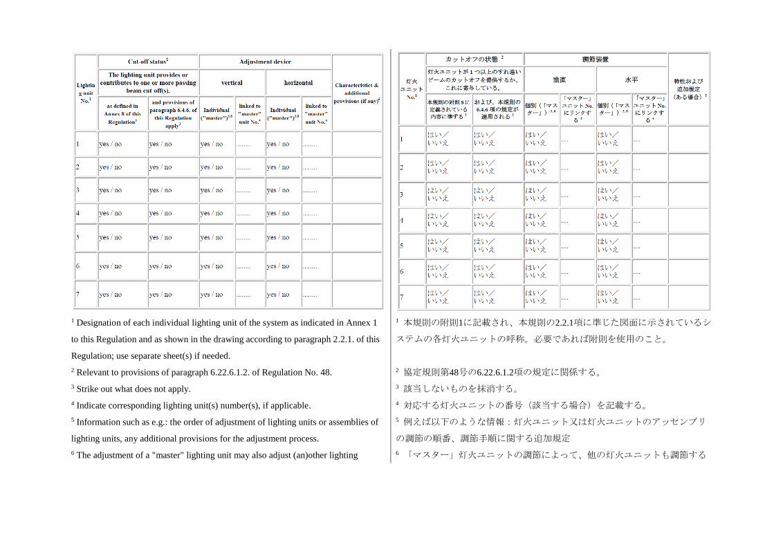
1 Designation of each individual lighting unit of the system as indicated in Annex 1
to this Regulation and as shown in the drawing according to paragraph 2.2.1. of this
Regulation; use separate sheet(s) if needed.
2 Relevant to provisions of paragraph 6.22.6.1.2. of Regulation No. 48.
3 Strike out what does not apply.
4 Indicate corresponding lighting unit(s) number(s), if applicable.
5 Information such as e.g.: the order of adjustment of lighting units or assemblies of
lighting units, any additional provisions for the adjustment process.
6 The adjustment of a "master" lighting unit may also adjust (an)other lighting
1 本規則の附則1に記載され、本規則の2.2.1項に準じた図面に示されているシ
ステムの各灯火ユニットの呼称。必要であれば附則を使用のこと。
2 協定規則第48号の6.22.6.1.2項の規定に関係する。
3 該当しないものを抹消する。
4 対応する灯火ユニットの番号(該当する場合)を記載する。
5 例えば以下のような情報:灯火ユニット又は灯火ユニットのアッセンブリ
の調節の順番、調節手順に関する追加規定
6 「マスター」灯火ユニットの調節によって、他の灯火ユニットも調節する
unit(s). ことができる。
Annex 11
Requirements for LED modules and adaptative front-lighting (AFS) including
LED modules
附則11
LEDモジュール及びLEDモジュール内蔵配光可変型前照灯システム(AFS)
に関する要件
1. General specifications
1.1.
Each LED module sample submitted shall conform to the relevant specifications of
this Regulation when tested with the supplied electronic light source control-gear(s),
if any.
1.2.
LED module(s) shall be so designed as to be and to remain in good working order
when in normal use. They shall moreover exhibit no fault in design or manufacture.
A LED module shall be considered to have failed if any one of its LEDs has failed.
1.3.
LED module(s) shall be tamperproof.
1.4.
The design of removable LED module(s) shall be such that:
1.4.1.
When the LED module is removed and replaced by another module provided by the
applicant and bearing the same light source module identification code, the
photometric specifications of the AFS shall be met;
1.4.2.
1. 一般仕様
1.1.
提出された各LEDモジュール供試品は、提供された電子式光源制御装置を用
いて(該当する場合)試験したときに、本規則の該当する仕様に適合しなけ
ればならない。
1.2.
LEDモジュールは、通常の使用において正常に作動し、且つ正常に作動し続
けるよう設計しなければならない。更に、設計又は製造上の欠陥が一切ない
ものとする。LEDモジュールのLEDのいずれかが故障した場合には、当該
LEDモジュールが故障したとみなす。
1.3.
LEDモジュールには、改造防止機能を備えていなければならない。
1.4.
取り外し可能なLEDモジュールは、以下のような設計にしなければならな
い。
1.4.1.
LEDモジュールを取り外し、申請者が提供した同一の光源モジュール識別コ
ードを有する別のモジュールと交換したとき、AFSの光度仕様が満たされな
ければならない。
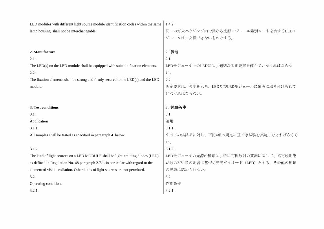
LED modules with different light source module identification codes within the same
lamp housing, shall not be interchangeable.
1.4.2.
同一の灯火ハウジング内で異なる光源モジュール識別コードを有するLEDモ
ジュールは、交換できないものとする。
2. Manufacture
2.1.
The LED(s) on the LED module shall be equipped with suitable fixation elements.
2.2.
The fixation elements shall be strong and firmly secured to the LED(s) and the LED
module.
2. 製造
2.1.
LEDモジュール上のLEDには、適切な固定要素を備えていなければならな
い。
2.2.
固定要素は、強度をもち、LED及びLEDモジュールに確実に取り付けられて
いなければならない。
3. Test conditions
3.1.
Application
3.1.1.
All samples shall be tested as specified in paragraph 4. below.
3.1.2.
The kind of light sources on a LED MODULE shall be light-emitting diodes (LED)
as defined in Regulation No. 48 paragraph 2.7.1. in particular with regard to the
element of visible radiation. Other kinds of light sources are not permitted.
3.2.
Operating conditions
3.2.1.
3. 試験条件
3.1.
適用
3.1.1.
すべての供試品に対し、下記4項の規定に基づき試験を実施しなければならな
い。
3.1.2.
LEDモジュールの光源の種類は、特に可視放射の要素に関して、協定規則第
48号の2.7.1項の定義に基づく発光ダイオード(LED)とする。その他の種類
の光源は認められない。
3.2.
作動条件
3.2.1.
LED module operating conditions
All samples shall be tested under the conditions as specified in paragraph 2.5. of
Annex 9. of this Regulation. If not specified differently in this annex LED modules
shall be tested inside the AFS as submitted by the manufacturer.
3.2.2.
Ambient temperature
For the measurement of electrical and photometric characteristics, the AFS shall be
operated in a dry and still atmosphere at an ambient temperature of 23 degrees C +/-
5 degrees C.
3.3.
Ageing
Upon the request of the applicant the LED module shall be operated for 15 hours and
cooled down to ambient temperature before starting the tests as specified in this
Regulation.
LEDモジュールの作動条件
すべての供試品に対し、本規則の附則9の2.5項に規定された条件を用いて、
試験を実施しなければならない。本附則に別段の規定がない限り、LEDモジ
ュールは、車両メーカー等が提出するAFSに内蔵された状態で試験しなけれ
ばならない。
3.2.2.
周囲温度
電気特性及び配光特性の測定においては、AFSを周囲温度23℃±5℃の乾燥し
た静止雰囲気中で作動させなければならない。
3.3.
慣らし点灯
申請者の要請があれば、LEDモジュールを15時間作動させ、その温度が周囲
温度まで下がるのを待ってから、本規則の規定に基づき試験を開始しなけれ
ばならない。
4. Specific specifications and tests 4. 特定の仕様及び試験
4.1.
Colour rendering
4.1.
演色
4.1.1.
Red content
In addition to measurements as described in paragraph 7. of this Regulation:
The minimum red content of the light of a LED module or AFS incorporating LED
module(s) tested at 50 V shall be such that:
4.1.1.
赤色成分
本規則の7項に規定された測定に加えて、
50Vで試験したLEDモジュール又はLEDモジュールが組み込まれたAFSの光の
赤色成分最小値は、以下の通りでなければならない。
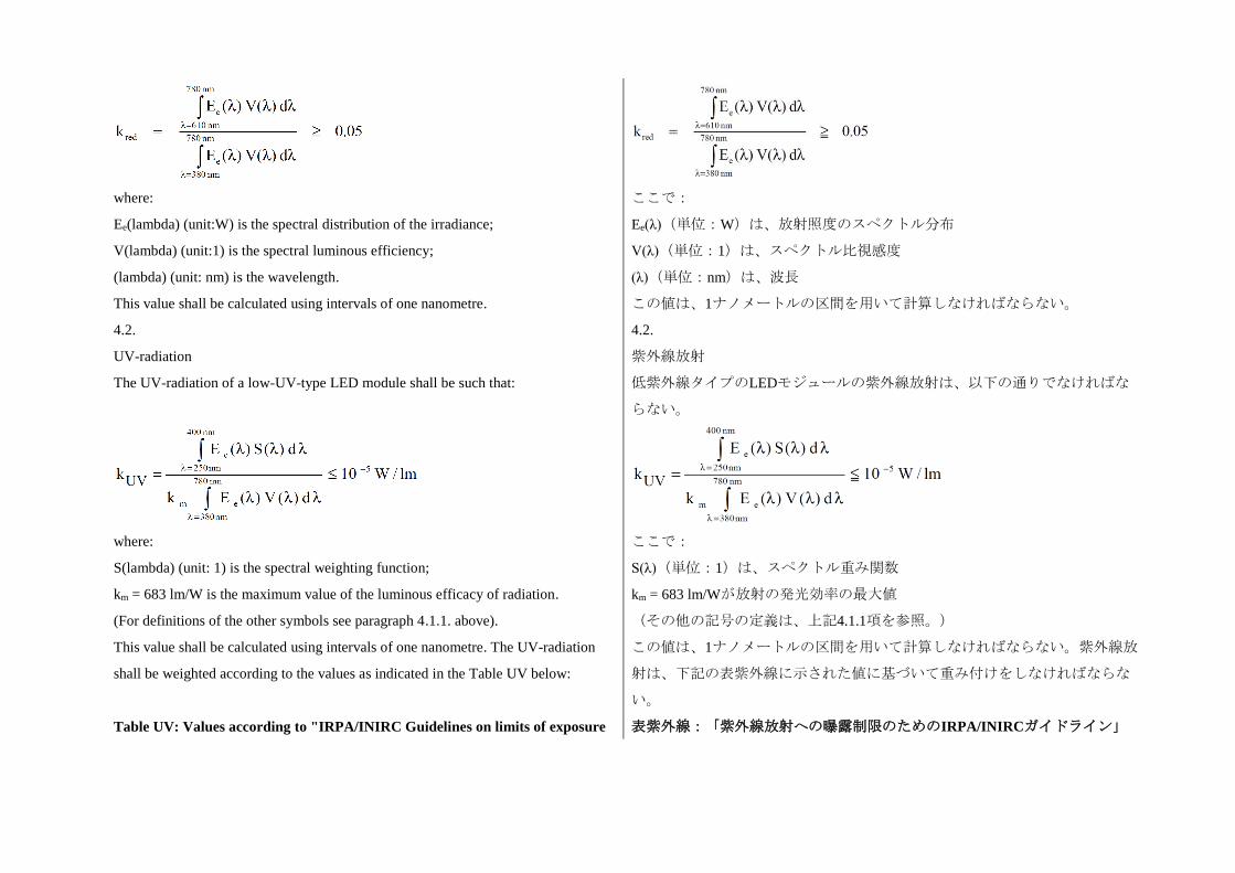
where:
Ee(lambda) (unit:W) is the spectral distribution of the irradiance;
V(lambda) (unit:1) is the spectral luminous efficiency;
(lambda) (unit: nm) is the wavelength.
This value shall be calculated using intervals of one nanometre.
ここで:
Ee(λ)(単位:W)は、放射照度のスペクトル分布
V(λ)(単位:1)は、スペクトル比視感度
(λ)(単位:nm)は、波長
この値は、1ナノメートルの区間を用いて計算しなければならない。
4.2.
UV-radiation
The UV-radiation of a low-UV-type LED module shall be such that:
where:
S(lambda) (unit: 1) is the spectral weighting function;
km = 683 lm/W is the maximum value of the luminous efficacy of radiation.
(For definitions of the other symbols see paragraph 4.1.1. above).
This value shall be calculated using intervals of one nanometre. The UV-radiation
shall be weighted according to the values as indicated in the Table UV below:
4.2.
紫外線放射
低紫外線タイプのLEDモジュールの紫外線放射は、以下の通りでなければな
らない。
ここで:
S(λ)(単位:1)は、スペクトル重み関数
km = 683 lm/Wが放射の発光効率の最大値
(その他の記号の定義は、上記4.1.1項を参照。)
この値は、1ナノメートルの区間を用いて計算しなければならない。紫外線放
射は、下記の表紫外線に示された値に基づいて重み付けをしなければならな
い。
Table UV: Values according to "IRPA/INIRC Guidelines on limits of exposure 表紫外線:「紫外線放射への曝露制限のためのIRPA/INIRCガイドライン」
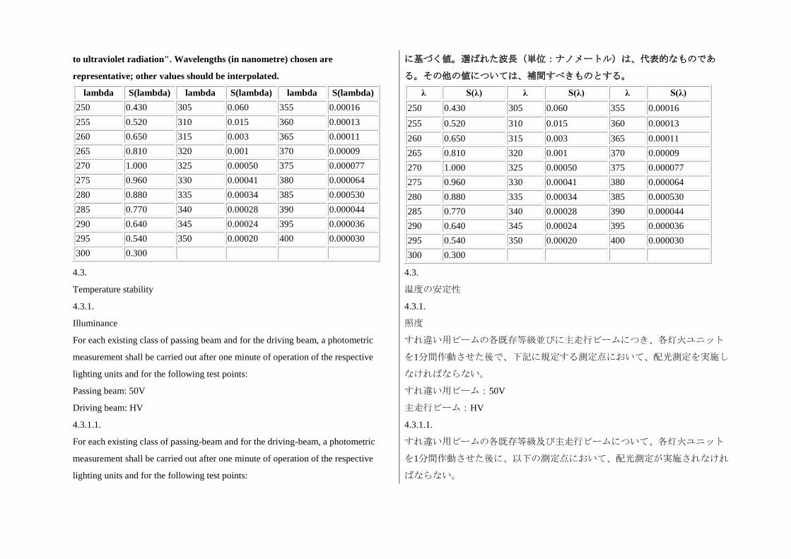
to ultraviolet radiation". Wavelengths (in nanometre) chosen are
representative; other values should be interpolated.
lambda S(lambda) lambda S(lambda) lambda S(lambda)
250 0.430 305 0.060 355 0.00016
255 0.520 310 0.015 360 0.00013
260 0.650 315 0.003 365 0.00011
265 0.810 320 0.001 370 0.00009
270 1.000 325 0.00050 375 0.000077
275 0.960 330 0.00041 380 0.000064
280 0.880 335 0.00034 385 0.000530
285 0.770 340 0.00028 390 0.000044
290 0.640 345 0.00024 395 0.000036
295 0.540 350 0.00020 400 0.000030
300 0.300
に基づく値。選ばれた波長(単位:ナノメートル)は、代表的なものであ
る。その他の値については、補間すべきものとする。
λ S(λ) λ S(λ) λ S(λ)
250 0.430 305 0.060 355 0.00016
255 0.520 310 0.015 360 0.00013
260 0.650 315 0.003 365 0.00011
265 0.810 320 0.001 370 0.00009
270 1.000 325 0.00050 375 0.000077
275 0.960 330 0.00041 380 0.000064
280 0.880 335 0.00034 385 0.000530
285 0.770 340 0.00028 390 0.000044
290 0.640 345 0.00024 395 0.000036
295 0.540 350 0.00020 400 0.000030
300 0.300
4.3.
Temperature stability
4.3.
温度の安定性
4.3.1.
Illuminance
For each existing class of passing beam and for the driving beam, a photometric
measurement shall be carried out after one minute of operation of the respective
lighting units and for the following test points:
Passing beam: 50V
Driving beam: HV
4.3.1.1.
For each existing class of passing-beam and for the driving-beam, a photometric
measurement shall be carried out after one minute of operation of the respective
lighting units and for the following test points:
4.3.1.
照度
すれ違い用ビームの各既存等級並びに主走行ビームにつき、各灯火ユニット
を1分間作動させた後で、下記に規定する測定点において、配光測定を実施し
なければならない。
すれ違い用ビーム:50V
主走行ビーム:HV
4.3.1.1.
すれ違い用ビームの各既存等級及び主走行ビームについて、各灯火ユニット
を1分間作動させた後に、以下の測定点において、配光測定が実施されなけれ
ばならない。
Passing-beam: 25RR
Driving-beam: HV
4.3.1.2.
Operation of the lighting units mentioned in paragraph 4.3.1.1. above shall then be
continued until photometric stability has occurred; this condition is considered to be
fulfilled if the variation of the illuminance for the test points indicated in paragraph
4.3.1.1. above is less than 3 per cent within any 15 minutes period. After photometric
stability has occurred, aiming for complete photometry shall be performed and the
photometric values at all required test points shall be determined.
4.3.1.3.
The ratio between the photometric values measured after one minute of operation
and those measured after photometric stability has occurred shall be calculated for
the test points indicated in paragraph 4.3.1.1. above. This ratio shall then be applied
to all other applicable test points to determine their photometric values after one
minute of operation.
4.3.1.4.
The illuminance values determined after one minute of operation and after
occurrence of photometric stability shall comply with applicable photometric
requirements.
すれ違い用ビーム:25RR
主走行ビーム:HV
4.3.1.2.
次いで、光度の安定性が生じるまで、上記4.3.1.1項に記載した灯火ユニット
の作動を続けなければならない。この条件は、上記4.3.1.1項に規定した測定
点に対する照度の変動が15分の間に3%未満になったとき満たされたとみな
す。光度の安定性が生じた後に、完全な配光測定のための照準調整を実施す
るものとし、必要なすべての測定点において配光測定値を求めなければなら
ない。
4.3.1.3.
上記4.3.1.1項に規定した測定点に対し、1分間作動させた後に測定した配光測
定値と光度の安定性が生じた後に測定した配光測定値との比率を計算しなけ
ればならない。次いで、この比率をその他すべての該当する測定点に適用し
て、1分間作動させた後の当該測定点における配光測定値を求めなければなら
ない。
4.3.1.4.
1分間作動させた後に測定した照度値と光度の安定性が生じた後に測定した照
度値は、該当する配光要件に適合しなければならない。
4.3.2.
Colour
The colour of the light emitted measured after one minute and measured after
photometric stability has been obtained, as described in paragraph 4.3.1.2. of this
annex, shall both be within the required colour boundaries.
4.3.2.
色
1分後に測定した発光色並びに本附則の4.3.1.2項の記載に基づき光度の安定性
が得られた後に測定した発光色は、いずれも必要な色の境界内に収まらなけ
ればならない。
5.
The measurement of the objective luminous flux of LED module(s) producing the
class C (basic) passing beam shall be carried out as follows:
5.
クラスC(基本的)すれ違いビームを発するLEDモジュールの目標光束値の
測定は、以下のとおり実施しなければならない:
5.1.
The LED module(s) shall be in the configuration as described in the technical
specification as defined in paragraph 2.2.2. of this Regulation. Optical elements
(secondary optics) shall be removed by the Technical Service at the request of the
applicant by the use of tools. This procedure and the conditions during the
measurements as described below shall be described in the test report.
5.1.
LEDモジュールは、本規則の2.2.2項に規定した技術仕様に記載された構成の
ものでなければならない。光学要素(補助光学装置)は、申請者の要請があ
れば、技術機関が工具を使用して取り外さなければならない。この手順並び
に下記に記載する測定時の条件は、試験報告書に記載しなければならない。
5.2.
Three LED modules of each type shall be submitted by the applicant with the light
source control gear, if applicable, and sufficient instructions.
Suitable thermal management (e.g. heat sink) may be provided, to simulate similar
thermal conditions as in the corresponding AFS application.
Before the test each LED module shall be aged for at least 72 hours under the same
conditions as in the corresponding AFS application.
In the case of an integrating sphere is used, the sphere shall have a minimum
diameter of one meter, and at least ten times the maximum dimension of the LED
module, whichever is the largest. The flux measurements can also be performed by
integration using a goniophotometer. The prescriptions in the CIE - Publication 84 -
1989, regarding the room temperature, positioning, etc., shall be taken into
consideration.
The LED module shall be burned in for approximately one hour in the closed sphere
or goniophotometer.
5.2.
申請者は、光源制御装置(該当する場合)並びに十分な指示とともに、各型
式のLEDモジュールを3個提出しなければならない。
該当するAFSの使用と類似する熱の状態を再現するために、適切な熱管理対
策(例:ヒートシンク)を設けることができる。
試験に先立ち、各LEDモジュールには、該当するAFSの使用と同じ条件で、
少なくとも72時間の慣らし点灯を施さなければならない。
積分球を使用する場合、積分球は、最低でも1mの直径を有し、且つ、最も大
きいLEDモジュールの最大寸法の少なくとも10倍の大きさを有しなければな
らない。光束の測定も、ゴニオフォトメータを用いて積分により実施するこ
とができる。室温、配置などに関しては、CIE規格84-1989の規定を考慮に入
れなければならない。
閉じた球又はゴニオフォトメータの中で約1時間、LEDモジュールのバーンイ
ンを行わなければならない。
The flux shall be measured after stability has occurred, as explained in paragraph
4.3.1.2. of this Annex.
The average of the measurements of the three samples of each type of LED module
shall be deemed to be its objective luminous flux.
光束の測定は、本附則の4.3.1.2項の説明に基づく安定性が生じた後で行わな
ければならない。
各型式のLEDモジュールの供試品3個を測定した結果の平均値をその目標光束
値とみなす。