Embed Size (px)
Citation preview
* KUBOTA Corporation Amagasaki-shi, Hyogo 660-0095 Japan
(Email: [email protected])
** School of Environmental Design College of Science and Engineering, Kanazawa University
Kanazawa-shi, Kanazawa 920-1192, Japan
(Email: [email protected])
Research of Earthquake Resistant Ductile Iron Pipe
(ERDIP) for fault crossing
K. Oda*, T. Ishihara* and M. Miyajima**
Abstract
This study proposes a method for designing a water pipeline system against fault displacements by
using Earthquake Resistant Ductile Iron Pipe (ERDIP). An ERDIP pipeline is capable of absorbing the
large ground displacements that occur during severe earthquakes by movement of its joints (expansion,
contraction, and deflection). Existing ERDIP pipelines have been exposed to several severe
earthquakes such as the 1995 Kobe Earthquake and the 2011 Great East Japan Earthquake, and there
has been no documentation of their failure in the last 40 years.
In the case of a pipeline that crosses a fault, there is the possibility of the occurrence of a local relative
displacement of several meters between the pipeline and the ground. Hence, the present study was
targeted at developing a method for designing an ERDIP pipeline that is capable of withstanding a
strike-slip fault. This was done by FEM analysis, wherein 1500-mm shell elements were used to model
the ERDIPs and spring elements were used to model the soil and ERDIP joints. An ERDIP pipeline
can accommodate a fault displacement of about 2 m and the use of a “large displacement absorption
unit” is an effective countermeasure for displacements exceeding 2 m.
INTRODUCTION
The 1995 Kobe Earthquake, which occurred just beneath the city, was caused by the movement of an
active fault. In Awaji-shima Island, the movement of Nojima-fault affected the ground surface and it
caused substantial damages to a lot of buildings [1], [2].
It has also been reported that the 1999 Chichi Earthquake in Taiwan and the 1999 Kocaeli Earthquake
in Turkey induced surface fault displacements that damaged buried pipelines. The damages included
compression and lateral deformations. Indeed, there have been instances when pipelines had to be
installed across known faults and this required the design of the pipelines to absorb surface fault
displacements.
An earthquake resistant ductile iron pipe (ERDIP) is capable of absorbing ground displacement in the
event of an earthquake. This is achieved through a joint expansion/contraction and deflection
mechanism. Over the past 40 years, ERDIP pipelines have been exposed to several earthquakes with
seismic intensities of above 6, as well as accompanying severe liquefaction, such as occurred in the
1995 Kobe Earthquake and the 2011 Great East Japan Earthquake. Despite this, there has been no
documented failure of an ERDIP pipeline. The earthquake resistance of ERDIP pipelines has been
confirmed through observation of the pipe movement, joint movement, and pipe stress during
earthquakes, as well as by liquefaction tests and post-earthquake surveys.
However, few studies have considered pipe movement and safety at fault crossings, and those that have
were limited to small pipelines. In the present study, we focused on large-diameter pipes such as those
of water systems, which could be damaged by an earthquake. We quantitatively measured the amount
of fault displacement that a normal pipeline of such diameter could absorb and investigated
countermeasures against large displacements.

ANALYSIS OF PIPELINE BEHAVIOR AT FAULT CROSSING
Structure of ERDIP and its behavior
Fig.1 shows the joint behavior of a US-type joint, a type of an ERDIP joint, the performance of which
was investigated in the present study. Table 1 gives the performance parameters of the joint. The joint is
capable of expanding/contracting by 0.5% of its standard pipe length (e.g., 4 m in the case of DN1500).
When the joint is fully expanded, the spigot projection and lock ring lock tightly together to prevent
leakage resulting from pull-out of the joint.
Fig.2 shows the pipeline behavior during ground crack and subsidence. When a pipe joint is fully
expanded or deflected, it may pull on other pipe joints one after the other to absorb the ground
deformation. The pipeline is thus referred to as a “chain structure pipeline”. Buried ERDIP joints are
not expanded by water pressure because the pipes are supported by the ground.
Outline of fault model
Institute of Earthquake and Volcano Geology, a
research institute of National Institute of
Advanced Industrial Science and Technology
(AIST), releases active fault database of Japan
since 2005. As of Jan. 20, 2015, 389 cases are
registered with fault displacement. Reverse fault is
about 50% of all faults and 90% of inclination
angles of these faults are 45°, 60° and 90°. Fig.3
shows distribution of displacement at active faults
in Japan. According to this data, about 50% of
active faults were displaced 2m or less. And about
75% of active faults were displaced 3m or less. In
addition, Table 2 shows that the displacements of
major faults in Los Angeles are mostly 3m or less.
FIG.1 Joint behavior of US-Type joint
(Normal state)
(Contracted state)
(Expanded state)
Table.1 Joint behavior of US-Type joint
Property Performance
Pull out resistance 3DkN(D:nominal daimeter mm)
Amount of
expansion/contraction±0.5% of pipe length
Deflection angle 4°(DN1500)
FIG.3 Fault displacement in Japan
Table 2 Major fault in Los Angeles, US
Fault nameSlip rate
(mm/year)
Average slip
(m)
Newport Inglewood 1.5 1.7
Palos Verdes 3.0 2.8
Raymond 1.5 1.7
San Fernando 5.0 1.8
Santa Susana 5.0 2.1
Sierra Madre 2.0 3.3
FIG.2 ERDIP pipeline behavior
Joint Pipe body
Axial force
(kN)
Deflection angle
(deg)
Stress
(MPa)
4,500 4.0 270
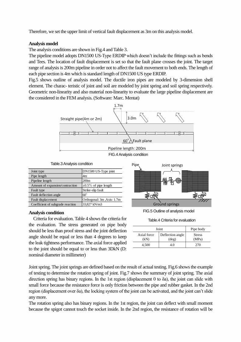
Therefore, we set the upper limit of vertical fault displacement as 3m on this analysis model.
Analysis model
The analysis conditions are shown in Fig.4 and Table 3.
The pipeline model adopts DN1500 US-Type ERDIP which doesn’t include the fittings such as bends
and Tees. The location of fault displacement is set so that the fault plane crosses the joint. The target
range of analysis is 200m pipeline in order not to affect the fault movement to both ends. The length of
each pipe section is 4m which is standard length of DN1500 US type ERDIP.
Fig.5 shows outline of analysis model. The ductile iron pipes are modeled by 3-dimension shell
element. The charac- teristic of joint and soil are modeled by joint spring and soil spring respectively.
Geometric non-linearity and also material non-linearity to evaluate the large pipeline displacement are
the considered in the FEM analysis. (Software: Marc. Mentat)
Analysis condition
Criteria for evaluation. Table 4 shows the criteria for
the evaluation. The stress generated on pipe body
should be less than proof stress and the joint deflection
angle should be equal or less than 4 degrees to keep
the leak tightness performance. The axial force applied
to the joint should be equal to or less than 3DkN (D:
nominal diameter in millimeter)
Joint spring. The joint springs are defined based on the result of actual testing. Fig.6 shows the example
of testing to determine the rotation spring of joint. Fig.7 shows the summary of joint spring. The axial
direction spring has binary regions. In the 1st region (displacement 0 to δa), the joint can slide with
small force because the resistance force is only friction between the pipe and rubber gasket. In the 2nd
region (displacement over δa), the locking system of the joint can be activated, and the joint can’t slide
any more.
The rotation spring also has binary regions. In the 1st region, the joint can deflect with small moment
because the spigot cannot touch the socket inside. In the 2nd region, the resistance of rotation will be
FIG.4 Analysis condition
Joint type DN1500 US-Type joint
Pipe length 4m
Pipeline lengrh 200m
Amount of expansion/contraction ±0.5% of pipe length
Fault type Strike-slip fault
Fault deflection angle 60°
Fault displacement Orthogonal: 3m ,Axis: 1.7m
Coefficient of subgrade reaction 33,827 kN/m3
Table.3 Analysis condition
FIG.5 Outline of analysis model
Table.4 Criteria for evaluation
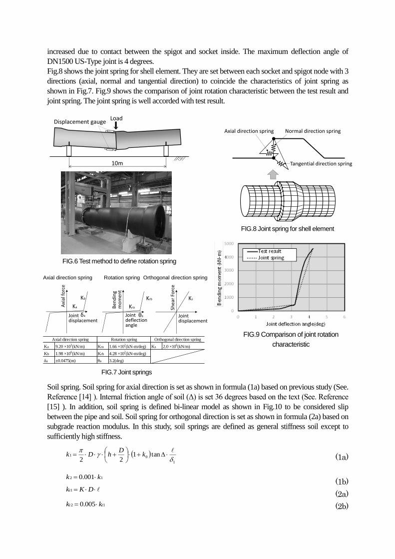
increased due to contact between the spigot and socket inside. The maximum deflection angle of
DN1500 US-Type joint is 4 degrees.
Fig.8 shows the joint spring for shell element. They are set between each socket and spigot node with 3
directions (axial, normal and tangential direction) to coincide the characteristics of joint spring as
shown in Fig.7. Fig.9 shows the comparison of joint rotation characteristic between the test result and
joint spring. The joint spring is well accorded with test result.
Soil spring. Soil spring for axial direction is set as shown in formula (1a) based on previous study (See.
Reference [14] ). Internal friction angle of soil (Δ) is set 36 degrees based on the text (See. Reference
[15] ). In addition, soil spring is defined bi-linear model as shown in Fig.10 to be considered slip
between the pipe and soil. Soil spring for orthogonal direction is set as shown in formula (2a) based on
subgrade reaction modulus. In this study, soil springs are defined as general stiffness soil except to
sufficiently high stiffness.
(1a)
(1b)
(2a)
(2b)
Displacement gauge
10m
Load
FIG.9 Comparison of joint rotation
characteristic
FIG.6 Test method to define rotation spring
FIG.8 Joint spring for shell element
FIG.7 Joint springs
Ka 9.20 ×10³(kN/m) Kra 1.66 ×10
2(kN-m/deg) Ks 2.0 ×10
6(kN/m)
Kb 1.98 ×10⁶(kN/m) Krb 4.28 ×10
2(kN-m/deg)
δa ±0.0475(m) θa 3.2(deg)
Axial direction spring Rotation spring Orthogonal direction spring
Kb
KaAxi
al fo
rce
Jointdisplacement
Krb
KraBen
din
g m
om
ent
Jointdeflectionangle
θa
Shea
r Fo
rce
Jointdisplacement
Ks
Axial direction spring Rotation spring Orthogonal direction spring
Kb
KaAxi
al fo
rce
Jointdisplacement
δa
Axial direction spring Normal direction spring
Tangential direction spring
Axial direction spring Normal direction spring
Tangential direction spring
1
01 tan122
k
DhDk
12 001.0 kk
DKkt1
12 005.0 tt kk
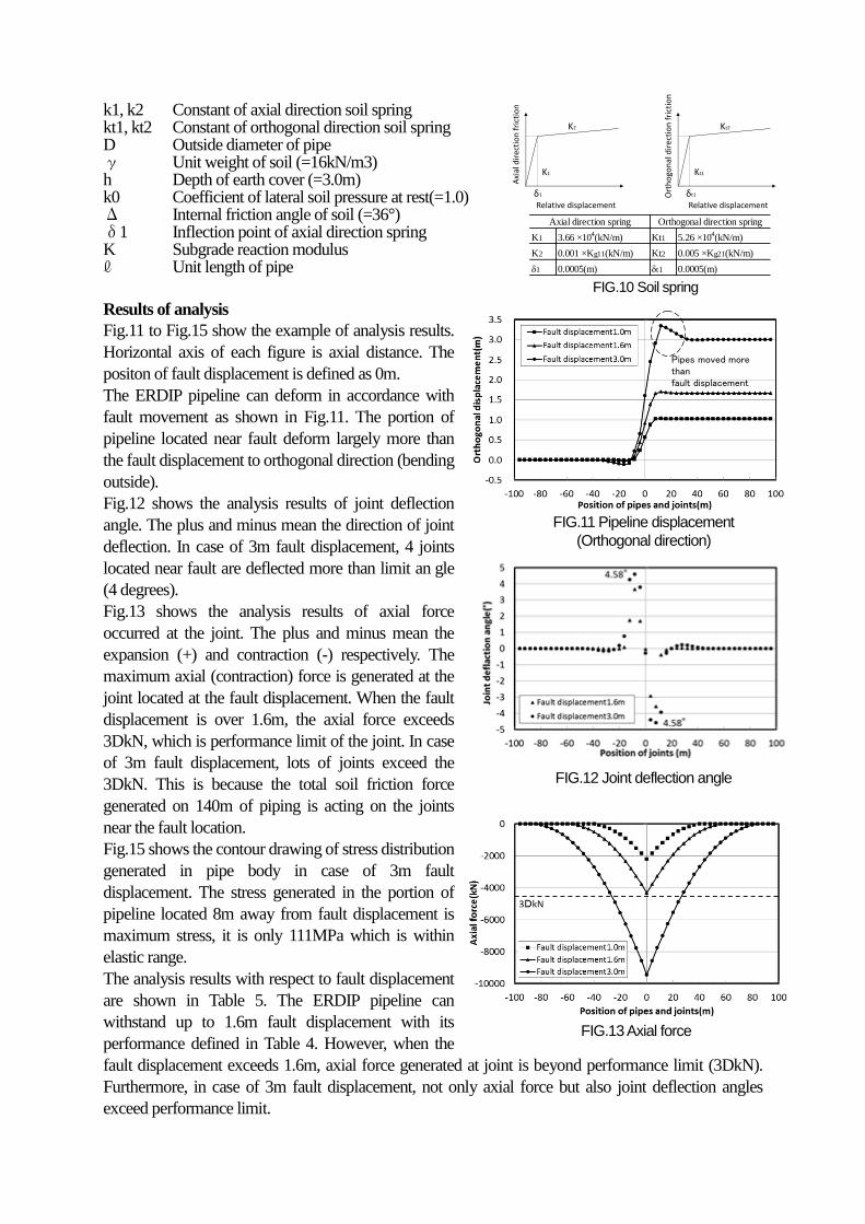
k1, k2 Constant of axial direction soil spring kt1, kt2 Constant of orthogonal direction soil spring D Outside diameter of pipe γ Unit weight of soil (=16kN/m3) h Depth of earth cover (=3.0m) k0 Coefficient of lateral soil pressure at rest(=1.0) Δ Internal friction angle of soil (=36°) δ1 Inflection point of axial direction spring K Subgrade reaction modulus ℓ Unit length of pipe
Results of analysis
Fig.11 to Fig.15 show the example of analysis results.
Horizontal axis of each figure is axial distance. The
positon of fault displacement is defined as 0m.
The ERDIP pipeline can deform in accordance with
fault movement as shown in Fig.11. The portion of
pipeline located near fault deform largely more than
the fault displacement to orthogonal direction (bending
outside).
Fig.12 shows the analysis results of joint deflection
angle. The plus and minus mean the direction of joint
deflection. In case of 3m fault displacement, 4 joints
located near fault are deflected more than limit an gle
(4 degrees).
Fig.13 shows the analysis results of axial force
occurred at the joint. The plus and minus mean the
expansion (+) and contraction (-) respectively. The
maximum axial (contraction) force is generated at the
joint located at the fault displacement. When the fault
displacement is over 1.6m, the axial force exceeds
3DkN, which is performance limit of the joint. In case
of 3m fault displacement, lots of joints exceed the
3DkN. This is because the total soil friction force
generated on 140m of piping is acting on the joints
near the fault location.
Fig.15 shows the contour drawing of stress distribution
generated in pipe body in case of 3m fault
displacement. The stress generated in the portion of
pipeline located 8m away from fault displacement is
maximum stress, it is only 111MPa which is within
elastic range.
The analysis results with respect to fault displacement
are shown in Table 5. The ERDIP pipeline can
withstand up to 1.6m fault displacement with its
performance defined in Table 4. However, when the
fault displacement exceeds 1.6m, axial force generated at joint is beyond performance limit (3DkN).
Furthermore, in case of 3m fault displacement, not only axial force but also joint deflection angles
exceed performance limit.
Pipes moved more than fault displacement
FIG.10 Soil spring
K1 3.66 ×10⁴(kN/m) Kt1 5.26 ×10
4(kN/m)
K2 0.001 ×Kg11(kN/m) Kt2 0.005 ×Kg21(kN/m)
δ1 0.0005(m) δt1 0.0005(m)
Axial direction spring Orthogonal direction spring
K1
K2
Axi
al d
irec
tio
n f
rict
ion
Relative displacement
Kt1
Kt2
Ort
ho
gon
al d
irec
tio
n f
rict
ion
Relative displacement
δ1 δt1
FIG.11 Pipeline displacement
(Orthogonal direction)
FIG.12 Joint deflection angle
FIG.13 Axial force
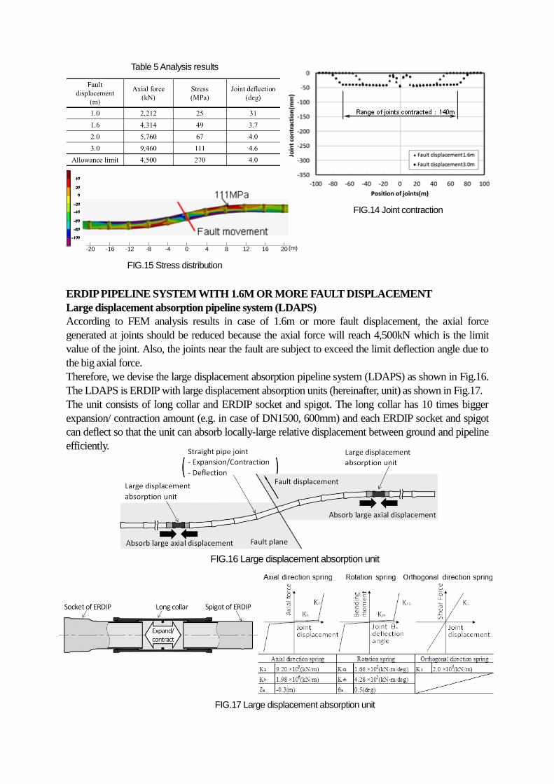
ERDIP PIPELINE SYSTEM WITH 1.6M OR MORE FAULT DISPLACEMENT
Large displacement absorption pipeline system (LDAPS)
According to FEM analysis results in case of 1.6m or more fault displacement, the axial force
generated at joints should be reduced because the axial force will reach 4,500kN which is the limit
value of the joint. Also, the joints near the fault are subject to exceed the limit deflection angle due to
the big axial force.
Therefore, we devise the large displacement absorption pipeline system (LDAPS) as shown in Fig.16.
The LDAPS is ERDIP with large displacement absorption units (hereinafter, unit) as shown in Fig.17.
The unit consists of long collar and ERDIP socket and spigot. The long collar has 10 times bigger
expansion/ contraction amount (e.g. in case of DN1500, 600mm) and each ERDIP socket and spigot
can deflect so that the unit can absorb locally-large relative displacement between ground and pipeline
efficiently.
Table 5 Analysis results
FIG.15 Stress distribution
0 4 8 12 16 20-12-16-20 -4-8 (m)
FIG.14 Joint contraction
FIG.16 Large displacement absorption unit
FIG.17 Large displacement absorption unit
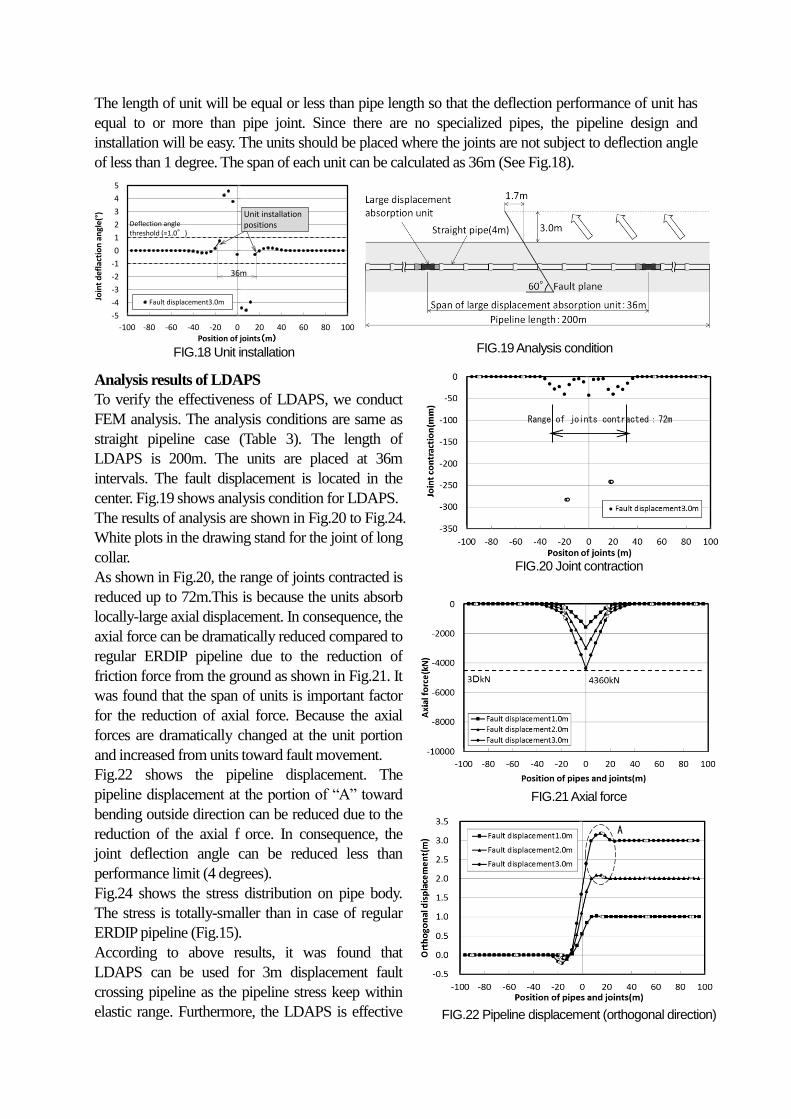
The length of unit will be equal or less than pipe length so that the deflection performance of unit has
equal to or more than pipe joint. Since there are no specialized pipes, the pipeline design and
installation will be easy. The units should be placed where the joints are not subject to deflection angle
of less than 1 degree. The span of each unit can be calculated as 36m (See Fig.18).
Analysis results of LDAPS
To verify the effectiveness of LDAPS, we conduct
FEM analysis. The analysis conditions are same as
straight pipeline case (Table 3). The length of
LDAPS is 200m. The units are placed at 36m
intervals. The fault displacement is located in the
center. Fig.19 shows analysis condition for LDAPS.
The results of analysis are shown in Fig.20 to Fig.24.
White plots in the drawing stand for the joint of long
collar.
As shown in Fig.20, the range of joints contracted is
reduced up to 72m.This is because the units absorb
locally-large axial displacement. In consequence, the
axial force can be dramatically reduced compared to
regular ERDIP pipeline due to the reduction of
friction force from the ground as shown in Fig.21. It
was found that the span of units is important factor
for the reduction of axial force. Because the axial
forces are dramatically changed at the unit portion
and increased from units toward fault movement.
Fig.22 shows the pipeline displacement. The
pipeline displacement at the portion of “A” toward
bending outside direction can be reduced due to the
reduction of the axial f orce. In consequence, the
joint deflection angle can be reduced less than
performance limit (4 degrees).
Fig.24 shows the stress distribution on pipe body.
The stress is totally-smaller than in case of regular
ERDIP pipeline (Fig.15).
According to above results, it was found that
LDAPS can be used for 3m displacement fault
crossing pipeline as the pipeline stress keep within
elastic range. Furthermore, the LDAPS is effective
-5
-4
-3
-2
-1
0
1
2
3
4
5
-100 -80 -60 -40 -20 0 20 40 60 80 100
Join
t d
efla
ctio
n a
ngl
e(°
)
Position of joints(m)
Fault displacement3.0m
Deflection anglethreshold (=1.0°)
Unit installation positions
36m
FIG.18 Unit installation FIG.19 Analysis condition
Range of joints contracted:72m
FIG.20 Joint contraction
FIG.21 Axial force
A
FIG.22 Pipeline displacement (orthogonal direction)
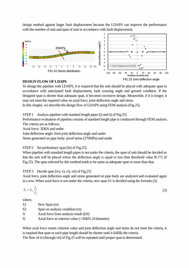
design method against larger fault displacement because the LDAPS can improve the performance
with the number of unit and span of unit in accordance with fault displacement.
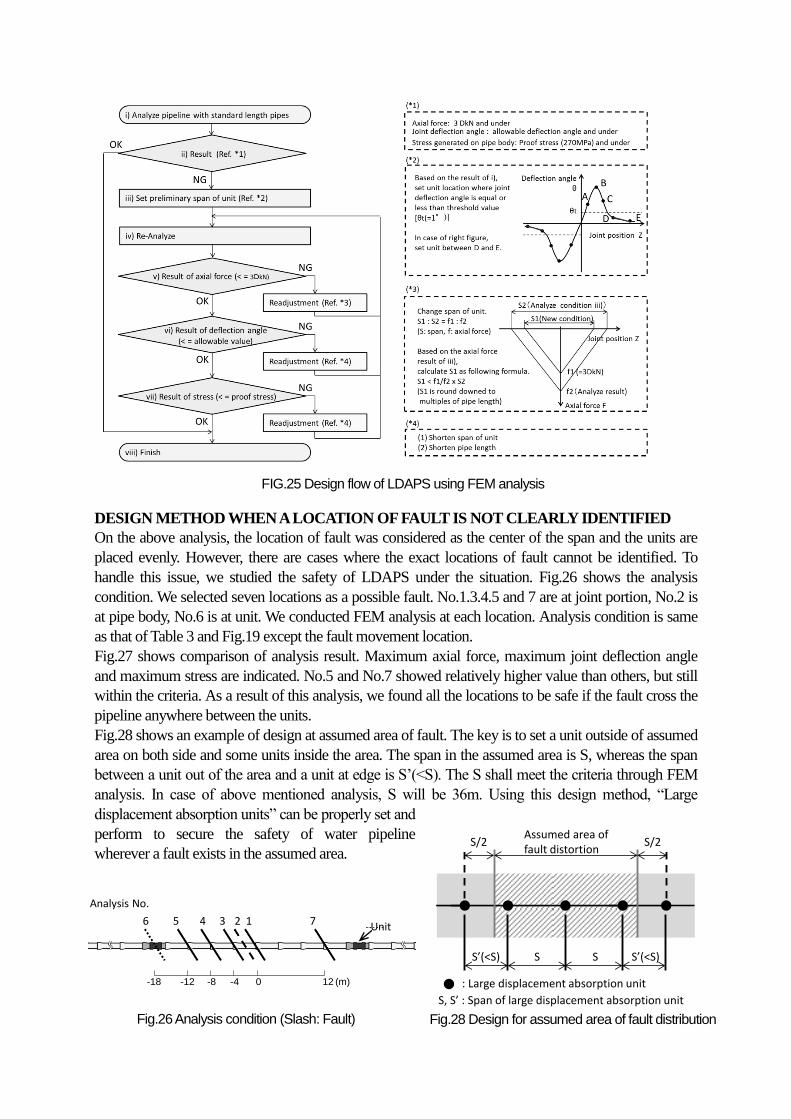
DESIGN FLOW OF LDAPS
To design the pipeline with LDAPS, it is required that the unit should be placed with adequate span in
accordance with anticipated fault displacement, fault crossing angle and ground condition. If the
designed span is shorter than adequate span, it becomes excessive design. Meanwhile, if it is longer, it
may not meet the required value on axial force, joint deflection angle and stress.
In this chapter, we describe the design flow of LDAPS using FEM analysis (Fig.25).
STEP 1 Analyze pipeline with standard length pipes [i) and ii) of Fig.25]
Performance evaluation of pipeline consists of standard length pipe is conducted through FEM analysis.
The criteria are as follows;
Axial force: 3DkN and under
Joint deflection angle: limit joint deflection angle and under
Stress generated on pipe body: proof stress (270MPa) and under
STEP 2 Set preliminary span [iii) of Fig.25]
When pipeline with standard length pipes is not under the criteria, the span of unit should be decided so
that the unit will be placed where the deflection angle is equal or less than threshold value θt (*2 of
Fig.25). The span selected by this method tends to be same as adequate span or more than that.
STEP 3 Decide span [iv), v), vi), vii) of Fig.25]
Axial force, joint deflection angle and stress generated on pipe body are analyzed and evaluated again
in a row. When axial force is not under the criteria, new span S1 is decided using the formula (3).
(3)
where,
S1 New Span (m)
S2 Span on analysis condition (m)
f1 Axial force from analysis result (kN)
f2 Axial force at criterion value (=3DkN, D:diameter)
When axial force meets criterion value and joint deflection angle and stress do not meet the criteria, it
is required that span or each pipe length should be shorter until it fulfills the criteria.
The flow of iv) through vii) of Fig.25 will be repeated until proper span is determined.
FIG.24 Stress distribution
-5
-4
-3
-2
-1
0
1
2
3
4
5
-100 -80 -60 -40 -20 0 20 40 60 80 100
Join
t d
efla
ctio
n a
ngl
e(°
)
Position of joints (m)
Fault displacement3.0m3.87°
3.75°
40
20
0
-20
-40
-60
-80
-100
(MPa)
85MPa
0 4 8 12 16 20-12-16-20 -4-8 (m)
FIG.23 Joint deflection angle
2
1
21f
fSS
DESIGN METHOD WHEN A LOCATION OF FAULT IS NOT CLEARLY IDENTIFIED
On the above analysis, the location of fault was considered as the center of the span and the units are
placed evenly. However, there are cases where the exact locations of fault cannot be identified. To
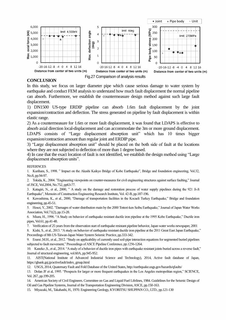
handle this issue, we studied the safety of LDAPS under the situation. Fig.26 shows the analysis
condition. We selected seven locations as a possible fault. No.1.3.4.5 and 7 are at joint portion, No.2 is
at pipe body, No.6 is at unit. We conducted FEM analysis at each location. Analysis condition is same
as that of Table 3 and Fig.19 except the fault movement location.
Fig.27 shows comparison of analysis result. Maximum axial force, maximum joint deflection angle
and maximum stress are indicated. No.5 and No.7 showed relatively higher value than others, but still
within the criteria. As a result of this analysis, we found all the locations to be safe if the fault cross the
pipeline anywhere between the units.
Fig.28 shows an example of design at assumed area of fault. The key is to set a unit outside of assumed
area on both side and some units inside the area. The span in the assumed area is S, whereas the span
between a unit out of the area and a unit at edge is S’(<S). The S shall meet the criteria through FEM
analysis. In case of above mentioned analysis, S will be 36m. Using this design method, “Large
displacement absorption units” can be properly set and
perform to secure the safety of water pipeline
wherever a fault exists in the assumed area.
FIG.25 Design flow of LDAPS using FEM analysis
Unit
0-4-8-12-18 (m)12
Analysis No.
1 2 3 5 6
4 7
Analysis No.
Unit6 5 4 3 2 1 7
Fig.26 Analysis condition (Slash: Fault)
S’(<S) S S S’(<S)
Assumed area of fault distortion
S/2S/2
S, S’ : Span of large displacement absorption unit
: Large displacement absorption unit
Fig.28 Design for assumed area of fault distribution
CONCLUSION
In this study, we focus on larger diameter pipe which cause serious damage to water system by
earthquake and conduct FEM analysis to understand how much fault displacement the normal pipeline
can absorb. Furthermore, we establish the countermeasure design method against such large fault
displacement.
1) DN1500 US-type ERDIP pipeline can absorb 1.6m fault displacement by the joint
expansion/contraction and deflection. The stress generated on pipeline by fault displacement is within
elastic range.
2) As a countermeasure for 1.6m or more fault displacement, it was found that LDAPS is effective to
absorb axial direction local-displacement and can accommodate the 3m or more ground displacement.
LDAPS consists of “Large displacement absorption unit” which has 10 times bigger
expansion/contraction amount than regular joint and ERDIP pipe.
3) “Large displacement absorption unit” should be placed on the both side of fault at the locations
where they are not subjected to deflection of more than 1 degree based. 4) In case that the exact location of fault is not identified, we establish the design method using “Large displacement absorption units”. REFERNCES
1. Kurihara, S., 1998. ” Impact on the Akashi Kaikyo Bridge of Kobe Earthquake”, Bridge and foundation engineering, Vol.32,
No.8, pp.94-97.
2. Tokida, K., 2004. ”Engineering viewpoints on counter-measures for civil engineering structures against surface faulting,” Journal
of JSCE, Vol.2004, No.752, pp63-77.
3. Katagiri, N., et al., 2000, ” A study on the damage and restoration process of water supply pipelines during the 921 Ji-Ji
Earthquake”, Memoirs of Construction Engineering Research Institute, Vol. 42-B, pp.187-196.
4. Kawashima, K., et al., 2000, “Damage of transportation facilities in the Kocaeli Turkey Earthquake,” Bridge and foundation
engineering, pp.45-51.
5. Hosoi, Y., 2002. ”Damages of water distribution main by the 2000 Tottori-ken Seibu Earthquake,” Journal of Japan Water Works
Association, Vol.71(2), pp.15-28.
6. Miura, H., 1996. “A Study on behavior of earthquake resistant ductile iron pipeline at the 1995 Kobe Earthquake,” Ductile iron
pipes, Vol.61, pp.41-48.
7. Verification of 25 years from the observation start of earthquake resistant pipeline behavior, Japan water works newspaper, 2001
8. Kishi, S., et al., 2013. “A study on behavior of earthquake resistant ductile iron pipeline at the 2011 Great East Japan Earthquake,”
Proceedings of 8th US-Taiwan-Japan Water System Seismic Practice, pp.333-342.
9. Erami ,M.H., et al., 2012. “Study on applicability of currently used soil-pipe interaction equations for segmented buried pipelines
subjected to fault movement,” Proceedings of ASCE Pipeline Conference, pp.1256-1264.
10. Kaneko ,S., et al., 2014. “A study of a behavior of ductile iron pipes with earthquake resistant joints buried across a reverse fault,”
Journal of structural engineering, vol.60A, pp.945-952.
11. AIST(National Institute of Advanced Industrial Science and Technology), 2014, Active fault database of Japan,
https://gbank.gsj.jp/activefault/index_gmap.html
12. USGS, 2014, Quaternary Fault and Fold Database of the United States, http://earthquake.usgs.gov/hazards/qfaults/
13. Dolan JF et al, 1995. “Prospects for larger or more frequent earthquakes in the Los Angeles metropolitan region,” SCIENCE,
Vol. 267, pp.199-205.
14. American Society of Civil Engineers. Committee on Gas and Liquid Fuel Lifelines, 1984. Guidelines for the Seismic Design of
Oil and Gas Pipeline Systems, Journal of the Transportation Engineering Division, ASCE, pp.150-163.
15. Miyazaki, M., Takahashi, H., 1970. Engineering Geology, KYORITSU SHUPPAN CO., LTD., pp.121-130
Fig.27 Comparison of analysis results