Embed Size (px)
Citation preview
Zezwala się na korzystanie z artykułu na warunkach licencji Creative Commons Uznanie autorstwa 3.0
1. Introduction
Robots are no longer associated solely with robotic arms, per-forming pre-programmed tasks in factories. We can observe a shift in focus from industrial robots towards mobile plat-forms. Such devices have found a broad spectrum of applica-tions among many different areas of industry, services, and science. Thanks to their versatility, it is common to find mobile robots exploring unreachable or even hostile environments. Machines are able to withstand uneasy conditions, survive extreme temperatures and pressure, even endure high radia-tion, and are ideal to substitute people in even the most unfriendly places.
Although advanced artificial intelligence algorithms may relieve the operator from some of his/her duties [1], it is undeni-able that, humans’ ability to interpret and analyse various phe-nomena is indispensable. That is why our emissaries, depending on the complexity of the mission, sometimes may need to be remotely controlled. To do so, the operator needs means and tools to remotely and directly control an on-board equipment.
2. Current trends in robotic arm control approaches
Numerous international researchers are focused on simplify-ing robotic arm control. They try to address the complexity of robot programming or its direct control using traditional means i.e. teach pedant, joysticks, even command line prompts.
During research, I came across various solutions to control pro-blem. Researchers used different methods of motion capture and its conversion into control signals for manipulators. We can distinguish two leading approaches to this issue. Non-mecha-nical methods are mostly based on the use of image interpre-tation, computer vision, and various 3D sensors. Mechanical set-ups use mechanisms that translate joints movement into control signals using rotation or shift sensors embedded in its structure.
One of the aforementioned approaches is using the 3D sen-sor. Many researchers favour Microsoft Kinect sensor. Originally built for Xbox game console, the device is capable of tracing limbs movement in real time. This feature results in easy to interpret data that can be used to control robotic arms [2, 3]. Another widely used sensor is Leap motion. This device uses infrared mesh to detect objects directly above it and capture its movement [4]. Although such solutions allow natural and intui-tive control over robotic arms, they lack in precision.
Another solution to the control problem is utilising com-puter vision. A set of cameras is placed around controlling arm. They track hand’s movements, using this information computer calculates coordinates in reference space. This data is used to control robotic arms [5, 6]. This approach can aid [7] or be used on-its-own to control robotic arms [8]. However, vision-based control requires high processing power to obtain data needed to control the manipulator. It is also prone to disturbances like inadequate lighting resulting in inaccurate position estimation.
Dissertation [9] that inspired me the most is a work about lower limbs rehabilitation equipment. A system that consists of a phantom-like device that rehabilitation technician wears is very similar to my idea of the two-arm system. It used the FPGA-based board to collect and interpret sensory data and provide data to an effector. A similar approach was taken by researchers aiming to aid rehabilitation of upper limbs. An exo-skeleton [10] is used to simulate simple tasks, like painting the wall, to help regain patient’s full dexterity. The undeniable advantage of such approach is high tracking accuracy and pre-cision of positioning.
Autor korespondujący: Maciej Rećko, [email protected]
Artykuł recenzowany nadesłany 25.05.2017 r., przyjęty do druku 28.06.2017 r.
Robotic Arm Control Using Phantom DeviceMaciej RećkoPolitechnika Białostocka, Wydział Mechaniczny, ul. Wiejska 45A, 15-351 Białystok, Poland
Abstract: Presented paper consists of consideration of an intuitive way of control of mobile robot’s robotic arm. A review of current control trends and methods in given scenario is presented. It is used to draw conclusions towards the creation of author’s control method. Author’s solution to this problem is a robotic arm – phantom device system. Created algorithm is presented in following part of the paper. Article includes preliminary quality tests conducted on a designed system. Research showed system’s satisfactory performance, although indicated parts that required fine-tuning. The paper concludes with a prediction of future development of the system, its algorithm and needed modifications in order to use in two arm control scenarios. Keywords: robotic arm, control algorithm, phantom device, mobile robot
85
Pomiary Automatyka Robotyka, ISSN 1427-9126, R. 21, Nr 2/2017, 85–89, DOI: 10.14313/PAR_224/85

All of the solutions mentioned above have their advantages towards desired control scenario. However, considering com-puter vision systems’ lack of desired precision, crucial to archieve adequate performance level during complex tasks, may not be the optimal one. Off-the-shelf mechanical solutions are used for control of the manipulator i.e. joystick. They bring a steep learning curve, as so they negate the idea of intuitiveness that is very important for the Author. The solution that this paper is focused on combines intuitiveness of tracing natural move-ments with the precision of mechanical solutions. A phantom device that allows tracing natural movements and allows precise control over each joint of the robotic arm.
3. Research problem
The inspiration for this work was found during preparation for an international robotic competition – University Rover Challenge (URC). It takes place yearly at Mars Desert Rese-arch Station near Hanksville in the United States. Challenge consists of four field tasks that require the use of the on-board robotic arm. Competitors are required to design and build rover analogues equipped with robotic arms able to perform specific tasks such as soil sample retrieval, equipment servicing or precise pick-up and delivery of cargo.
Dexterity and resilience of competing solutions are as important as reliability and accuracy of performed operations. During the competition, teams cannot see rover and must rely solely on sensory information or video-feed of on-bard cameras. This scenario closely resembles use of military robots, UAV’s in marine exploration, or rovers.
Conventional means of controlling such manipulators is based on joystick use. Most teams, including mine, favour this solution, although it bears some limitations. The most important one is the inability to manipulate objects in 3D space efficiently. Those observations lead to an idea of a robotic arm-phantom system that would improve operation’s performance.
Project’s objective is set on improving control or the rover’s manipulator. The solution needs to be intuitive, easy to use and more precise than the method used to date. A kinematic “twin” of the robotic arm – phantom is a proposed answer to the prob-lem. I decided to create such device and equip it with algorithms corresponding to two possible control modes, applicable to the robotic arm’s software. The device’s performance will be com-pared with most commonly used joystick controller to evaluate possible improvement in the control approach.
Phantom system and improvement in arm’s control resulted in several works [11–13] that constituted an introduction to the conducted research, part of which this article is. The ultimate idea is to create a two-arm system that would be carried like a backpack and could control up to two robotic arms. To achieve this goal, I decided to take small steps and experiment with dif-ferent algorithms and solutions. Core algorithm was tested on a test system, and operators’ experience and performance are used to propose improvements to it.
4. Robot-phantom system
The first part of my work required the construction of robotic arm and phantom to cooperate closely. As a base for a robo-tic arm, a manipulator of #next team’s RED rover was used. It has five rotational joints that enable 5 DoFs. Each joint is equipped with high accuracy rotational potentiometers used to determine the relative position of each link. Main rover’s computer further interprets data. Signals from potentiometers were fed to an analogue-to-digital converter. Afterwards, digi-tal data was encapsulated into a data frame and transmitted via a radio modem.
On the other side of the system was a phantom device (Fig. 1). This device is a kinematic equivalent of the corre-sponding robotic arm. It consists of the base (1), three rota-tional joints (2, 4, 6), three rigid links (3, 5, 7)) and simulated end effector’s tip (9). Each of its joints is equipped with a poten-tiometer (8) to measure the relative rotation of each link. Data is transmitted using custom designed Arduino shield. This shield was attached to an Intel Edison prototype board. I chose this solution based on full Arduino’s hardware compliance, high resolution of its ADC and computing power. Similar to the manipulator, sensory information was converted by means of ADCs and further delivered as an input for control algorithm. Communication between rover and phantom was realised using radio modems and matching data exchange protocol, using data frames designed to carry control and sensory information.
5. The algorithm and its implementation
Communication between rover and phantom can be achieved using two work modes. Mode one- angle coordinates and Car-tesian coordinate’s modes are distinguished with frame pream-ble marker. Both carry different data. Using angle coordinates operator has full control over the robotic arm. Manipulator recreates each joint position within the acceptable error mar-gin. This mode is useful in rare cases of very limited work-space, where links must be oriented in one specific manner. XYZ coordinates carry information about the position of the end effector only. An algorithm calculating inverse kinematics comes up with a solution. This mode requires more processing power but enables movements along straight lines with far more accurate rendition than angle mode. Two ways of control were designed and implemented to utilise and test two possible approaches to control of the rover’s manipulator.
A developed algorithm is depicted in figure 2. It represents two branches that correspond with two possible control sce-narios. The decision is based on an entry in the preamble of device’s code. The algorithm was implemented on Intel Edison prototype board and tested.
On rover’s side of the system, the less complicated algorithm is used (Fig. 3). It is only a part of complex rover’s software and runs as a subroutine of Robotic Arm Control Processing Unit. This part is responsible for the recreation of movements guided with the phantom. It enables Cartesian and the “angle coordinate system” control. On-board motor controller calcu-lates PWM signals based on the control modes and uses set-
Fig. 1. Developed phantom deviceRys. 1. Opracowany fantom
86
Robotic Arm Control Using Phantom Device
P O M I A R Y • A U T O M A T Y K A • R O B O T Y K A NR 2/2017
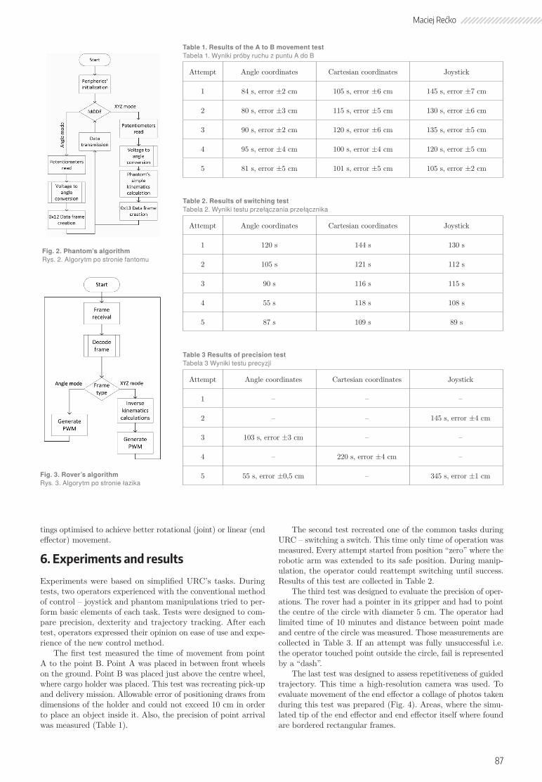
tings optimised to achieve better rotational (joint) or linear (end effector) movement.
6. Experiments and results
Experiments were based on simplified URC’s tasks. During tests, two operators experienced with the conventional method of control – joystick and phantom manipulations tried to per-form basic elements of each task. Tests were designed to com-pare precision, dexterity and trajectory tracking. After each test, operators expressed their opinion on ease of use and expe-rience of the new control method.
The first test measured the time of movement from point A to the point B. Point A was placed in between front wheels on the ground. Point B was placed just above the centre wheel, where cargo holder was placed. This test was recreating pick-up and delivery mission. Allowable error of positioning draws from dimensions of the holder and could not exceed 10 cm in order to place an object inside it. Also, the precision of point arrival was measured (Table 1).
The second test recreated one of the common tasks during URC – switching a switch. This time only time of operation was measured. Every attempt started from position “zero” where the robotic arm was extended to its safe position. During manip-ulation, the operator could reattempt switching until success. Results of this test are collected in Table 2.
The third test was designed to evaluate the precision of oper-ations. The rover had a pointer in its gripper and had to point the centre of the circle with diameter 5 cm. The operator had limited time of 10 minutes and distance between point made and centre of the circle was measured. Those measurements are collected in Table 3. If an attempt was fully unsuccessful i.e. the operator touched point outside the circle, fail is represented by a “dash”.
The last test was designed to assess repetitiveness of guided trajectory. This time a high-resolution camera was used. To evaluate movement of the end effector a collage of photos taken during this test was prepared (Fig. 4). Areas, where the simu-lated tip of the end effector and end effector itself where found are bordered rectangular frames.
Fig. 2. Phantom’s algorithm Rys. 2. Algorytm po stronie fantomu
Fig. 3. Rover’s algorithm Rys. 3. Algorytm po stronie łazika
Table 1. Results of the A to B movement test Tabela 1. Wyniki próby ruchu z puntu A do B
Attempt Angle coordinates Cartesian coordinates Joystick
1 84 s, error ±2 cm 105 s, error ±6 cm 145 s, error ±7 cm
2 80 s, error ±3 cm 115 s, error ±5 cm 130 s, error ±6 cm
3 90 s, error ±2 cm 120 s, error ±6 cm 135 s, error ±5 cm
4 95 s, error ±4 cm 100 s, error ±4 cm 120 s, error ±5 cm
5 81 s, error ±5 cm 101 s, error ±5 cm 105 s, error ±2 cm
Table 2. Results of switching test Tabela 2. Wyniki testu przełączania przełącznika
Attempt Angle coordinates Cartesian coordinates Joystick
1 120 s 144 s 130 s
2 105 s 121 s 112 s
3 90 s 116 s 115 s
4 55 s 118 s 108 s
5 87 s 109 s 89 s
Table 3 Results of precision test Tabela 3 Wyniki testu precyzji
Attempt Angle coordinates Cartesian coordinates Joystick
1 – – –
2 – – 145 s, error ±4 cm
3 103 s, error ±3 cm – –
4 – 220 s, error ±4 cm –
5 55 s, error ±0,5 cm – 345 s, error ±1 cm
87
Maciej Rećko

Presented collage indicates accurate tracing of desired tra-jectory. The TCP point of the phantom and the tip of the end effector moved the same distance without visible disturbances or unwanted slowdowns along a linear trajectory. The test was conducted three times, always results were consistent.
7. Conclusions
Analysing results of each test brings a conclusion that every ope-ration performed using phantom was comparable if not better than the conventional method. Results show improvement in operation time and movement precision. Even tracing of sub-jected movement trajectory was accurate. Although individual precision test could not be considered failure, it does not pro-vide enough data to state if this quality has improved or not.
Tables 1 and 2 indicate gradual improvement over conven-tional control method. Both tests show marginal advantage of control in the angle coordinate system over the Cartesian. This is possibly caused by the addition of positioning errors during manipulation that required operator’s corrections during move-ment. Precision test, although not fully successful, may suggest that overall control improved in successful attempts.
Operators comments about their control experience, were that it was easier to guide end effector to the desired place with full control over each joint compared to a single-joint control that joystick allows. Drawing from their experience, presented control method is one of the easiest and simplest, they have tried so far. Operators pointed that it was natural for them to grab the phantom device and guide it especially, when operation required linear movements like during “switching” test. It was their suggestion that ability to experience the grasping force of the gripper would be a welcome addition. The evaluation shows that research is moving in right direction and the method may find real life application.
8. Future works
The concept of two robotic arm control system is in its early development stage. Future research would focus on the design of two-arm phantom itself. The approach would benefit from further analysis of current research state and broader scope of problem solutions. Currently, primary areas of focus are set on accurate recreation of arm’s movement using the phantom-like device.
Developing haptic feedback that will allow the operator to “feel” the environment and manipulate object was second goal. Presented paper neglected the influence of possible disturbances. I plan on extending my work on this project of this aspect. Fur-ther, a development of the full robot-phantom system is sched-
uled – a system that will find application in mobile research platforms.
AcknowledgmentThis research was conducted as a part of the own work (MB/WM/15/2017) financed by Bialystok University of Technology.
References
1. Kim W.S., Diaz-Calderon A., Peters S.F., Carsten J.L., Leger C., Onboard Centralized Frame Tree Database for Intelligent Space Operations of the Mars Science Laboratory Rover, “IEEE Transactions on Cybernetics”, Vol. 44, No. 11,2014, 2109–2121,
DOI: 10.1109/TCYB.2014.2301442.2. Haselirad A., Neubert J., A novel Kinect-based system for 3D
moving object interception with a 5-DOF robotic arm, [in:] IEEE International Conference on Automation Science and Engineering, Vol. 2015–Octob., 117–124,
DOI: 10.1109/CoASE.2015.7294049.3. Moreno R.J., Tracking of Human Operator Arms Oriented To
The Control Of Two Robotic Arms, [in:] 2014 XIX Symposium on Image, Signal Processing and Artificial Vision, 2014, 3–6, DOI: 10.1109/STSIVA.2014.7010125.
4. Leal-Cardenas G., Medina-Nino G., La Rosa F.D., Proposal for Natural Human-Robot Interaction through the Use of Robotic Arms, [in:] Proceedings of 12th LARS Latin American Robot-ics Symposium and 3rd SBR Brazilian Symposium on Robot-ics LARS-SBR 2015 – Part Robot. Conf. 2015, 85–90, DOI: 10.1109/LARS-SBR.2015.23.
5. Waldherr S., Romero R., Thrun S., A Gesture Based Interface for Human-Robot Interaction, “Autonomous Robots”, Vol. 9, No. 2, 2000, 151–173,
DOI: 10.1023/A:1008918401478.6. Kofman J., Wu X., Luu T.J., Verma S., Teleoperation of
a Robot Manipulator Using a Vision-Based Human–Robot Interface, “IEEE Transactions on Industrial Electronics”, Vol. 52, Iss. 5, 2005, 1206–1219,
DOI: 10.1109/TIE.2005.855696.7. Park C.H., Howard A.M., Vision-based force guidance for
improved human performance in a teleoperative manipula-tion system, [in:] IEEE International Conference on Intelli-gent Robots and Systems, 2007, 2126–2131, DOI: 10.1109/IROS.2007.4399119.
8. Selvaggio M., Chen F., Gao B., Notomista G., Trapani F., Caldwell D., Vision based virtual fixture generation for teleop-erated robotic manipulation, [in:] 2016 International Conference on Advanced Robotics and Mechatronics, 2016, 190–195, DOI: 10.1109/ICARM.2016.7606917.
9. Ostaszewski M., Synteza układu sterowania o strukturze rów-noległo-szeregowej, rozprawa doktorska, Akademia Górniczo--Hutnicza, Kraków 2015.
10. Carignan C., Tang J., Roderick S., Development of an exoskel-eton haptic interface for virtual task training, [in:] 2009 IEEE/RSJ International Conference on Intelligent Robots and Sys-tems, 3697–3702,
DOI: 10.1109/IROS.2009.5354834.11. Czaplicki P., Rećko M., Tołstoj-Sienkiewicz J., Robotic arm
control system for mars rover analogue, [in:] 21st International Conference on Methods and Models in Automation and Robot-ics, MMAR 2016,
DOI: 10.1109/MMAR.2016.7575295.12. Dzierżek K., Rećko M., Pietrala D.S., Quick prototyping of
manipulator control system with PLC controller, [in:] 23rd International Conference ENGINEERING MECHANICS 2017, 15–18 May 2017, 294–297.
13. Rećko M., Projekt fantoma do zdalnego sterowania robo-tem, praca magisterska, Politechnika Białostocka, Biały-stok 2016.
Fig. 4. Collage of pictures that depict movement trajectory tracing Rys. 4. Kolaż prezentujący śledzenie trajektorii ruchu
88
Robotic Arm Control Using Phantom Device
P O M I A R Y • A U T O M A T Y K A • R O B O T Y K A NR 2/2017
Streszczenie: Przedmiotem pracy było opracowanie intuicyjnego systemu sterowania manipulatorem robota mobilnego. Przedstawiono obecne kierunki rozwoju sterowania oraz przegląd zastosowanych metod w przypadku sterowania nadążnego. Na podstawie obserwacji wyciągnięto wnioski, które stanowią podstawę rozważań nad autorskim rozwiązaniem. Proponowanym rozwiązaniem problemu sterowania jest układ manipulator – fantom. Opracowano algorytm, który został zaprezentowany w dalszej części artykułu. Zawarto również wyniki wstępnych badań jakości sterowania zaprojektowanego systemu. Badania wykazały zadowalającą wydajność rozwiązania oraz wskazały miejsca, w których należałoby dokonać niezbędnych usprawnień. Praca jest zakończona planami dalszego rozwoju projektu oraz propozycją modyfikacji, które pozwoliłyby na stworzenie systemu do sterowania dwoma ramionami.
Słowa kluczowe: : ramię robota, algorytm sterowania, urządzenie fantomowe, robot mobilny
Sterowanie manipulatorem za pomocą fantomu
Maciej Rećko, MSc [email protected]
Maciej Rećko holds a M.Sc. Eng. in Automatic Control and Robotics from the Bialystok University of Techno-logy. He was a member of the Hyperion Team that won University Rover Chal-lenge 2014. His work on Mars rover ana-logues continued after he took over as a coordinator of the #next team- cre-ators of #next and RED rovers awarded in several international competitions. Currently, he is a PhD candidate at the Faculty of Mechanical Engineering in the field of Construction and Maintenance of Machinery. His research topics revolve around robotic arm’s control, mobile robots and use of such robots in challenging environments.
89
Maciej Rećko