Embed Size (px)
Citation preview
Rotational-State-Dependent Dispersion of Molecules by Pulsed Optical Standing Waves
Xing Nan Sun,1,2 Lee Yeong Kim,3 Bum Suk Zhao (조범석),2,3,* and Doo Soo Chung1,*1Department of Chemistry, Seoul National University, Seoul, Korea
2Department of Chemistry, Ulsan National Institute of Science and Technology, Ulsan, Korea3Department of Physics, Ulsan National Institute of Science and Technology, Ulsan, Korea
(Received 14 July 2015; published 24 November 2015)
We report on the rotational-state-dependent, transverse acceleration of CS2 molecules affected by pulsedoptical standing waves. The steep gradient of the standing wave potential imparts far stronger dipole forceson the molecules than propagating pulses do. Moreover, large changes in the transverse velocities (i.e., upto 80 m=s) obtained with the standing waves are well reproduced in numerical simulations using theeffective polarizability that depends on the molecular rotational states. Our analysis based on the rotational-state-dependent effective polarizability can therefore serve as a basis for developing a new technique ofstate selection for both polar and nonpolar molecules.
DOI: 10.1103/PhysRevLett.115.223001 PACS numbers: 37.10.Vz, 33.15.-e, 33.80.-b, 37.20.+j
During the last two decades, optical manipulation ofmolecules has been an important subject in many exper-imental and theoretical studies. A nonresonant laser fieldexerts a dipole force on molecules proportional to themolecular polarizability. Propagating nonresonant laserfields have been used to control the angular, transverse,and longitudinal motions of molecules. Strong laser pulseshave been used to align molecules [1,2]. A combinationwith an electrostatic field produces an orientation of polarmolecules [3–8]. Focusing a molecular beam [9] andseparating a molecular mixture beam [10] were proposed,and a molecule lens [11–13] and a molecule prism [14]have been realized. It was also suggested that moleculescould be decelerated using a nonresonant laser field[15,16]. Coupling between the angular and the translationalmotions enabled the adjustments of the deceleration byaligning the molecules with the laser field [17,18]. Inaddition, efficient control of molecular deflection bypreshaping the angular distribution was discussed [19,20].On the other hand, the standing wave potential, formed
by two counterpropagating lasers, has been employed tocontrol the forward velocity of molecules. An atom andmolecule mirror made of a pulsed standing wave wassuggested [21]. An accelerator [22] and a decelerator [23]for atoms and molecules using pulsed traveling standingwaves with increasing and decreasing velocities, respec-tively, were discussed. Furthermore, the possibility ofslowing down and bunching molecules by means of atraveling potential with a constant velocity was studied[24]. These theoretical studies were followed by exper-imental realizations. A pulsed standing wave changed thevelocity distribution of hydrogen molecules by 200 m=s[25]. Traveling potentials with constant velocities wereused to decrease the velocity of NO molecules [26] and toprepare stationary benzene molecules [27]. Recently, thevelocity of metastable argon atoms initially trapped in a
magneto-optical trap was accelerated by an acceleratingperiodic potential [28].The angular motions of molecules determine their
effective polarizabilities, which in turn affect their trans-lational motions in a manner dependent on the rotationalstates. Thus the interaction between molecules and laserfields was recognized to be rotational-state-dependent[1,2,4,9,10,19,20,29–31], and the possibility of separatingquantum states with laser fields was discussed in theoreticalstudies [10,19,20,29–32]. However, almost all the exper-imental results [2,11–14,17,26,27] were analyzed using asingle polarizability value averaged over all quantum states.Here we report on the transverse dispersion of a CS2
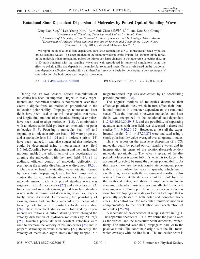
molecular beam by pulsed optical standing waves and itsinterpretation in terms of the rotational-state-dependentmolecular polarizability. The velocity spread of the dis-persed molecules is about 160 m=s, which is too large to beaccounted for solely by using the average polarizability. Forthis reason, we use the rotational-state-dependent polar-izability to simulate the velocity spreads, which are inexcellent agreement with the experimental results. In thisway, we demonstrate the dependence of the dipole force onthe rotational states, and show its importance in under-standing molecular transverse motions affected by opticalstanding waves. Our report therefore serves as a corner-stone for developing a new state-selection technique that ispotentially applicable to both polar and nonpolar mole-cules. The control over the molecular transverse motion iscomplementary to the deceleration and acceleration ofmolecules [25–28].A schematic of the experimental setup is shown in Fig. 1.
The apparatus operates at 10 Hz. We define the y and z axesas the vertical and the molecular beam directions, respec-tively. The infrared laser (IR1) propagates parallel to thepositive x axis. The coordinate origin is at the IR1 focus,which overlaps with the IR2 focus. The molecular beam is
PRL 115, 223001 (2015) P HY S I CA L R EV I EW LE T T ER Sweek ending
27 NOVEMBER 2015
0031-9007=15=115(22)=223001(5) 223001-1 © 2015 American Physical Society
formed by seeding 0.3 vol% CS2 vapor in Ar gas andexpanding the mixture, held at a pressure of 2 atm, througha pulsed valve of a nozzle into a vacuum chamber. Withsimilar source conditions, the rotational temperature T wasestimated to be 35 K in the previous report [17]. Afterpassing through a skimmer, the molecular beam enters asecond chamber at 1 × 10⁻⁷ Torr. The molecular beam isthen collimated by a pinhole. At 8.5 cm downstream fromthe nozzle, the molecular beam is crossed by a pulsedstanding wave potential.The pulsed standing wave is created by overlapping two
counterpropagating pulses (IR1 and IR2) with the samepeak intensity I0 at the center of the second chamber. Theirpulse width and wavelength are τ ¼ 12.5 ns (FWHM) andλ ¼ 1064 nm, respectively. The two pulses are formed bysplitting a single pulse from an injection-seeded Nd∶YAGlaser. After splitting, the energy and polarization of the twopulses are adjusted by two sets of a zero-order half-waveplate and a Glan-Laser polarizer, respectively. Then the twopulses, which are linearly polarized along the y axis, arefocused by two lenses with focal lengths of 20 cm into thesecond chamber. The waist radius ω0 of the pulsesis 21 μm.After a delay of 30 ns, the molecular beam, which has
interacted with the pulsed standing wave potential, inter-sects with an lineraly polarized ultraviolet (UV) probe laserpulse which is a third-harmonic of another Nd:YAG laserwith τ ¼ 7.1 ns and λ ¼ 355 nm. The lens in front of thesecond chamber also focuses the UV pulse. Consideringthe delay of 30 ns, the UV laser focus is also spatiallyshifted along the z axis to ionize only the dispersedmolecules through multiphoton ionization processes.The dispersed and subsequently ionized molecules are
accelerated and focused by an electrostatic lens system ontoa microchannel plate (MCP) after flying 67 cm through atime-of-flight (TOF) tube. Three electrodes, a repeller(900 V), an extractor (600 V), and a ground provide thevelocity map imaging condition [33]. In this way, thetransverse velocity of an ion is measured from the ratio
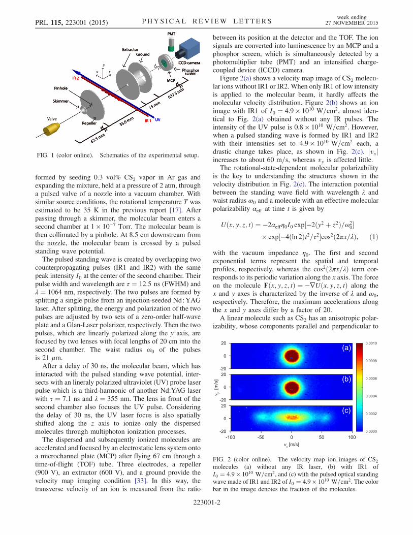
between its position at the detector and the TOF. The ionsignals are converted into luminescence by an MCP and aphosphor screen, which is simultaneously detected by aphotomultiplier tube (PMT) and an intensified charge-coupled device (ICCD) camera.Figure 2(a) shows a velocity map image of CS2 molecu-
lar ions without IR1 or IR2. When only IR1 of low intensityis applied to the molecular beam, it hardly affects themolecular velocity distribution. Figure 2(b) shows an ionimage with IR1 of I0 ¼ 4.9 × 10¹⁰ W=cm2, almost iden-tical to Fig. 2(a) obtained without any IR pulses. Theintensity of the UV pulse is 0.8 × 10¹⁰ W=cm2. However,when a pulsed standing wave is formed by IR1 and IR2with their intensities set to 4.9 × 10¹⁰ W=cm2 each, adrastic change takes place, as shown in Fig. 2(c). jvxjincreases to about 60 m=s, whereas vy is affected little.The rotational-state-dependent molecular polarizability
is the key to understanding the structures shown in thevelocity distribution in Fig. 2(c). The interaction potentialbetween the standing wave field with wavelength λ andwaist radius ω0 and a molecule with an effective molecularpolarizability αeff at time t is given by
Uðx; y; z; tÞ ¼ −2αeffη0I0 exp½−2ðy2 þ z2Þ=ω20�
× exp½−4ðln 2Þt2=τ2�cos2ð2πx=λÞ; ð1Þ
with the vacuum impedance η0. The first and secondexponential terms represent the spatial and temporalprofiles, respectively, whereas the cos2ð2πx=λÞ term cor-responds to its periodic variation along the x axis. The forceon the molecule Fðx; y; z; tÞ ¼ −∇Uðx; y; z; tÞ along thex and y axes is characterized by the inverse of λ and ω0,respectively. Therefore, the maximum accelerations alongthe x and y axes differ by a factor of 20.A linear molecule such as CS2 has an anisotropic polar-
izability, whose components parallel and perpendicular to
FIG. 1 (color online). Schematics of the experimental setup.
FIG. 2 (color online). The velocity map ion images of CS2molecules (a) without any IR laser, (b) with IR1 ofI0 ¼ 4.9 × 10¹⁰ W=cm2, and (c) with the pulsed optical standingwave made of IR1 and IR2 of I0 ¼ 4.9 × 10¹⁰ W=cm2. The colorbar in the image denotes the fraction of the molecules.
PRL 115, 223001 (2015) P HY S I CA L R EV I EW LE T T ER Sweek ending
27 NOVEMBER 2015
223001-2
themolecular axis are α∥ and α⊥, respectively.When a linearmolecule is oriented at a polar angle θ with respect to thelaser polarization axis, the effective polarizability is givenby αeff ¼ ðα∥ − α⊥Þcos2θ þ α⊥. For a rotational statejJ;Mi,
cos2θ¼hJ;Mjcos2θjJ;Mi¼1
3þ2
3
JðJþ1Þ−3M2
ð2Jþ3Þð2J−1Þ : ð2Þ
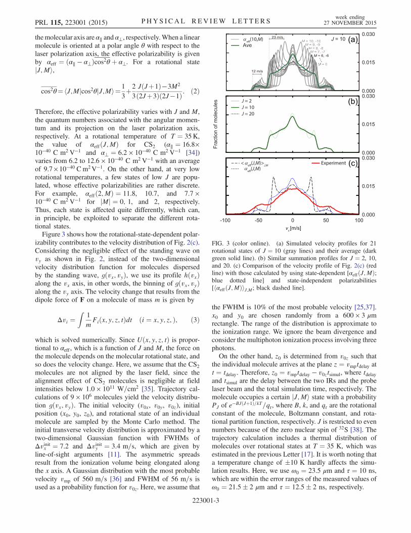
Therefore, the effective polarizability varies with J and M,the quantum numbers associated with the angular momen-tum and its projection on the laser polarization axis,respectively. At a rotational temperature of T ¼ 35K,the value of αeffðJ;MÞ for CS2 (α∥ ¼ 16.8×10−40 C m2V−1 and α⊥ ¼ 6.2 × 10−40 C m2V−1 [34])varies from 6.2 to 12.6 × 10−40 C m2V−1 with an averageof 9.7×10−40 Cm2V−1. On the other hand, at very lowrotational temperatures, a few states of low J are popu-lated, whose effective polarizabilities are rather discrete.For example, αeffð2;MÞ ¼ 11.8, 10.7, and 7.7 ×10−40 C m2V−1 for jMj ¼ 0; 1, and 2, respectively.Thus, each state is affected quite differently, which can,in principle, be exploited to separate the different rota-tional states.Figure 3 shows how the rotational-state-dependent polar-
izability contributes to the velocity distribution of Fig. 2(c).Considering the negligible effect of the standing wave onvy as shown in Fig. 2, instead of the two-dimensionalvelocity distribution function for molecules dispersedby the standing wave, gðvx; vyÞ, we use its profile hðvxÞalong the vx axis, in other words, the binning of gðvx; vyÞalong the vy axis. The velocity change that results from thedipole force of F on a molecule of mass m is given by
Δvi ¼Z
1
mFiðx; y; z; tÞdt ði ¼ x; y; z; Þ; ð3Þ
which is solved numerically. Since Uðx; y; z; tÞ is propor-tional to αeff , which is a function of J and M, the force onthe molecule depends on the molecular rotational state, andso does the velocity change. Here, we assume that the CS2molecules are not aligned by the laser field, since thealignment effect of CS2 molecules is negligible at fieldintensities below 1.0 × 10¹¹ W=cm2 [35]. Trajectory cal-culations of 9 × 10⁶ molecules yield the velocity distribu-tion gðvx; vyÞ. The initial velocity (v0x, v0y, v0z), initialposition (x0, y0, z0), and rotational state of an individualmolecule are sampled by the Monte Carlo method. Theinitial transverse velocity distribution is approximated by atwo-dimensional Gaussian function with FWHMs ofΔvinitx ¼ 7.2 and Δvinity ¼ 3.4 m=s, which are given byline-of-sight arguments [11]. The asymmetric spreadsresult from the ionization volume being elongated alongthe x axis. A Gaussian distribution with the most probablevelocity vmp of 560 m=s [36] and FWHM of 56 m=s isused as a probability function for v0z. Here, we assume that
the FWHM is 10% of the most probable velocity [25,37].x0 and y0 are chosen randomly from a 600 × 3 μmrectangle. The range of the distribution is approximate tothe ionization range. We ignore the beam divergence andconsider the multiphoton ionization process involving threephotons.On the other hand, z0 is determined from v0z such that
the individual molecule arrives at the plane z ¼ vmptdelay att ¼ tdelay. Therefore, z0 ¼ vmptdelay − v0ztsimul, where tdelayand tsimul are the delay between the two IRs and the probelaser beam and the total simulation time, respectively. Themolecule occupies a certain jJ;Mi state with a probabilityPJ of e−BJðJþ1Þ=kT=qr, where B, k, and qr are the rotationalconstant of the molecule, Boltzmann constant, and rota-tional partition function, respectively. J is restricted to evennumbers because of the zero nuclear spin of 32S [38]. Thetrajectory calculation includes a thermal distribution ofmolecules over rotational states at T ¼ 35 K, which wasestimated in the previous Letter [17]. It is worth noting thata temperature change of �10 K hardly affects the simu-lation results. Here, we use ω0 ¼ 23.5 μm and τ ¼ 10 ns,which are within the error ranges of the measured values ofω0 ¼ 21.5� 2 μm and τ ¼ 12.5� 2 ns, respectively.
FIG. 3 (color online). (a) Simulated velocity profiles for 21rotational states of J ¼ 10 (gray lines) and their average (darkgreen solid line). (b) Similar summation profiles for J ¼ 2, 10,and 20. (c) Comparison of the velocity profile of Fig. 2(c) (redline) with those calculated by using state-dependent [αeffðJ;MÞ;blue dotted line] and state-independent polarizabilities[hαeffðJ;MÞiJ;M; black dashed line].
PRL 115, 223001 (2015) P HY S I CA L R EV I EW LE T T ER Sweek ending
27 NOVEMBER 2015
223001-3
In Fig. 3(a), 21 profiles of hðvx; J ¼ 10;MÞ are drawn ingray lines, assuming that all the molecules occupy eachjJ ¼ 10;Mi state. Since hðvx; J ¼ 10;MÞ ¼ hðvx; J ¼10;−MÞ, they are overlapped in Fig. 3(a) and the totalnumber of the profiles is 21. In each profile, there are strongrainbowlike singularities associated with the existence ofthe maxima (minima) in the deflecting standing wave [39],whose positions move outward as jMj decreases—i.e., asαeff increases. As αeffð10; jMjÞ ranges from 6.7 (jMj ¼ 10)to 11.5 ðjMj ¼ 0Þ × 10−40 Cm2V−1, the positions of theinner and the outer singularities span from �12 to �35 andfrom�46 to�58 m=s, respectively. The congestions of theprofiles near �35 and �58 m=s manifest the unimodalrainbow feature in the distribution of αeff , which waspredicted by Gershnabel and Averbukh [20]. Thegreen solid line in Fig. 3(a) represents the average of the21 profiles ½1=ð2 × 10þ 1Þ�P10
M¼−10 hðvx; J ¼ 10;MÞ,which is the convolution of the two types of rainbowlikesingularities. Note that the inner singularities are smearedout owing to the large distribution of their positions. Incontrast, the spread of the positions of the outer singularityforms two broad small peaks in the green profile.Figure 3(b) shows ½1=ð2J þ 1Þ�PJ
M¼−J hðvx; J;MÞ forJ ¼ 2, 10, and 20. These three J states are selected because,at T ¼ 35 K, the population of the rotational energy levelshas its maximum at J ¼ 10, and is close to half of themaximum at J ¼ 2 and 20. Note that the profile for J ¼ 2 ismore structured than the other two. Furthermore, the twoprofiles for J ¼ 10 and 20 are almost identical.The blue dotted profile in Fig. 3(c) isPJ;MPJhðvx; J;MÞ obtained by considering the rotational
states up to J ¼ 98. The inner rainbowlike peaks of theprofile are smeared out, though the outer ones leave smallpeaks, as in Fig. 3(b). These features also appear in the redline in Fig. 3(c), which is the profile of the measuredvelocity distribution in Fig. 2(c). The black dashed line inFig. 3(c) depicts h½vx; αeffðTÞ�, assuming that all themolecules possess the same polarizability αeffðTÞ ¼hαeffðJ;MÞiJ;M. This profile is almost identical to the thickgray profile in Fig. 3(a)—i.e., the profile for jJ ¼ 10;M ¼ �6i with αeff ¼ 9.8 × 10−40 C m2V−1. It showsdistinctive inner singularities, which clearly disagrees
with the experimental result. For these reasons, the state-dependent effective polarizability can be identified as thecrucial contribution to the final velocity distribution.The velocity distribution of the dispersed molecules in a
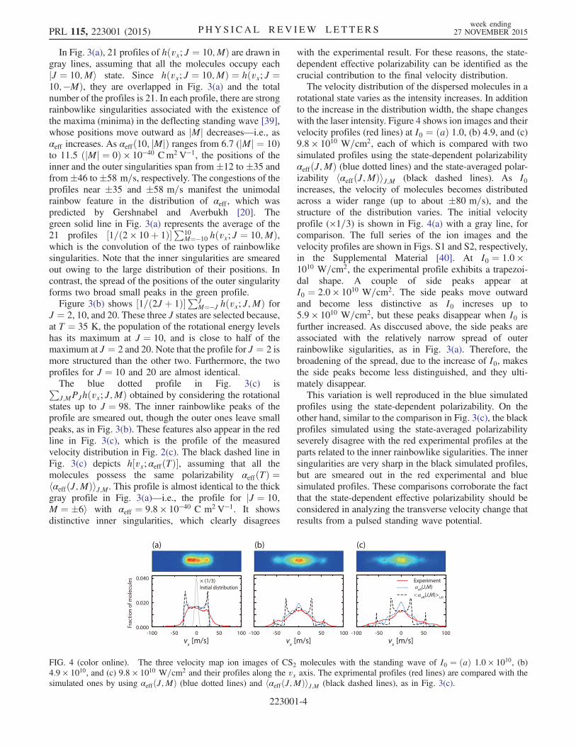
rotational state varies as the intensity increases. In additionto the increase in the distribution width, the shape changeswith the laser intensity. Figure 4 shows ion images and theirvelocity profiles (red lines) at I0 ¼ ðaÞ 1.0, (b) 4.9, and (c)9.8 × 10¹⁰ W=cm2, each of which is compared with twosimulated profiles using the state-dependent polarizabilityαeffðJ;MÞ (blue dotted lines) and the state-averaged polar-izability hαeffðJ;MÞiJ;M (black dashed lines). As I0increases, the velocity of molecules becomes distributedacross a wider range (up to about �80 m=s), and thestructure of the distribution varies. The initial velocityprofile (×1=3) is shown in Fig. 4(a) with a gray line, forcomparison. The full series of the ion images and thevelocity profiles are shown in Figs. S1 and S2, respectively,in the Supplemental Material [40]. At I0 ¼ 1.0 ×10¹⁰ W=cm2, the experimental profile exhibits a trapezoi-dal shape. A couple of side peaks appear atI0 ¼ 2.0 × 10¹⁰ W=cm2. The side peaks move outwardand become less distinctive as I0 increses up to5.9 × 1010 W=cm2, but these peaks disappear when I0 isfurther increased. As disccused above, the side peaks areassociated with the relatively narrow spread of outerrainbowlike sigularities, as in Fig. 3(a). Therefore, thebroadening of the spread, due to the increase of I0, makesthe side peaks become less distinguished, and they ulti-mately disappear.This variation is well reproduced in the blue simulated
profiles using the state-dependent polarizability. On theother hand, similar to the comparison in Fig. 3(c), the blackprofiles simulated using the state-averaged polarizabilityseverely disagree with the red experimental profiles at theparts related to the inner rainbowlike sigularities. The innersingularities are very sharp in the black simulated profiles,but are smeared out in the red experimental and bluesimulated profiles. These comparisons corroborate the factthat the state-dependent effective polarizability should beconsidered in analyzing the transverse velocity change thatresults from a pulsed standing wave potential.
FIG. 4 (color online). The three velocity map ion images of CS2 molecules with the standing wave of I0 ¼ ðaÞ 1.0 × 10¹⁰, (b)4.9 × 10¹⁰, and (c) 9.8 × 10¹⁰ W=cm2 and their profiles along the vx axis. The exprimental profiles (red lines) are compared with thesimulated ones by using αeffðJ;MÞ (blue dotted lines) and hαeffðJ;MÞiJ;M (black dashed lines), as in Fig. 3(c).
PRL 115, 223001 (2015) P HY S I CA L R EV I EW LE T T ER Sweek ending
27 NOVEMBER 2015
223001-4
Together with other state-of-the-art techniques, such as apulsed supersonic expansion source [41] and optical stand-ing waves of a tunable velocity [26,28], the state-dependentdispersion is expected to enable state selection of nonpolarmolecules. The relative velocity of molecules to the movingstanding wave can be made such that only the state of thehighest αeff is trapped in the standing wave potential. In thisway, the trapped state can be separated from otheruntrapped states. The detailed scheme of the state selectionis described in the Supplemental Material [40]. This newmethod will nicely complement the techniques for the stateselection of polar molecules [42,43]. Especially, this opticaltechnique can be exploited to separate and analyze mixturesof nonpolar conformers, isotopes of homonuclear diatomicmolecules, or their spin isomers.In conclusion, we observed the rotational-state-
dependent dispersion of CS2 molecules by optical standingwaves. Simulations using the state-dependent polarizabil-ities provided better agreement with the experimentalobservations as compared with simulations based on theaverage (state-independent) polarizability. This paves theway for selecting a specific state of nonpolar molecules.
This work was supported by the Basic Science ResearchProgram through the National Research Foundation ofKorea funded by the Ministry of Education, Scienceand Technology (NRF-2013R1A1A2059715 and NRF-2012R1A1A1041789). B. S. Z. acknowledges supportfrom the T. J. Park Science Fellowship.X. N. S. and L. Y. K. contributed equally to this work.
*Corresponding [email protected]
[1] B. Friedrich and D. Herschbach, Phys. Rev. Lett. 74, 4623(1995).
[2] H. Stapelfeldt and T. Seideman, Rev. Mod. Phys. 75, 543(2003).
[3] B. Friedrich and D. Herschbach, J. Chem. Phys. 111, 6157(1999).
[4] B. Friedrich and D. Herschbach, J. Phys. Chem. A 103,10280 (1999).
[5] L. Cai, J. Marango, and B. Friedrich, Phys. Rev. Lett. 86,775 (2001).
[6] H. Sakai, S. Minemoto, H. Nanjo, H. Tanji, and T. Suzuki,Phys. Rev. Lett. 90, 083001 (2003).
[7] M. Härtelt and B. Friedrich, J. Chem. Phys. 128, 224313(2008).
[8] J. H. Nielsen, H. Stapelfeldt, J. Küpper, B. Friedrich, J. J.Omiste, and R. González-Férez, Phys. Rev. Lett. 108,193001 (2012).
[9] T. Seideman, J. Chem. Phys. 106, 2881 (1997).[10] T. Seideman, J. Chem. Phys. 107, 10420 (1997).[11] H. Stapelfeldt, H. Sakai, E. Constant, and P. B. Corkum,
Phys. Rev. Lett. 79, 2787 (1997).[12] B. S. Zhao et al., Phys. Rev. Lett. 85, 2705 (2000).[13] H. S. Chung, B. S. Zhao, S. H. Lee, S. Hwang, K. Cho,
S.-H. Shim, S.-M. Lim, W. K. Kang, and D. S. Chung, J.Chem. Phys. 114, 8293 (2001).
[14] B. S.Zhao, S. H.Lee,H. S.Chung, S.Hwang,W. K.Kang,B.Friedrich, andD. S. Chung, J. Chem. Phys. 119, 8905 (2003).
[15] B. Friedrich, Phys. Rev. A 61, 025403 (2000).[16] R. Fulton, A. I. Bishop, and P. F. Barker, Phys. Rev. Lett. 93,
243004 (2004).[17] S. M. Purcell and P. F. Barker, Phys. Rev. Lett. 103, 153001
(2009).[18] S. M. Purcell and P. F. Barker, Phys. Rev. A 82, 033433
(2010).[19] E. Gershnabel and I. S. Averbukh, Phys. Rev. Lett. 104,
153001 (2010).[20] E. Gershnabel and I. S. Averbukh, Phys. Rev. A 82, 033401
(2010).[21] P. Ryytty and M. Kaivola, Phys. Rev. Lett. 84, 5074 (2000).[22] P. F. Barker and M. N. Shneider, Phys. Rev. A 64, 033408
(2001).[23] P. F. Barker and M. N. Shneider, Phys. Rev. A 66, 065402
(2002).[24] G. Dong, W. Lu, and P. F. Barker, Phys. Rev. A 69, 013409
(2004).[25] J. Ramirez-Serrano, K. E. Strecker, and D.W. Chandler,
Phys. Chem. Chem. Phys. 8, 2985 (2006).[26] R. Fulton, A. I. Bishop, M. N. Shneider, and P. F. Barker,
Nat. Phys. 2, 465 (2006).[27] A. I. Bishop, L. Wang, and P. F. Barker, New J. Phys. 12,
073028 (2010).[28] C. Maher-McWilliams, P. Douglas, and P. F. Barker, Nat.
Photonics 6, 386 (2012).[29] E. Gershnabel and I. S. Averbukh, J. Chem. Phys. 134,
054304 (2011).[30] E. Gershnabel and I. S. Averbukh, J. Chem. Phys. 135,
084307 (2011).[31] E. Gershnabel, M. Shapiro, and I. S. Averbukh, J. Chem.
Phys. 135, 194310 (2011).[32] S. Fleischer, I. S. Averbukh, and Y. Prior, Phys. Rev. Lett.
99, 093002 (2007).[33] A. T. J. B. Eppink and D. H. Parker, Rev. Sci. Instrum. 68,
3477 (1997).[34] J. O. Hirschfelder, C. F. Curtiss, and R. B. Bird, Molecular
Theory of Gases and Liquids (Wiley, New York, 1954).[35] R. Velotta, N. Hay, M. B. Mason, M. Castillejo, and J. P.
Marangos, Phys. Rev. Lett. 87, 183901 (2001).[36] G. Scoles, D. Bassi, U. Buck, and U. Valbusa, Atomic and
Molecular Beam Methods (Oxford University Press, NewYork, 1988).
[37] S. M.Purcell, Ph.D. thesis,UniversityCollegeLondon, 2010.[38] R. Torres, R. de Nalda, and J. P. Marangos, Phys. Rev. A 72,
023420 (2005).[39] P. Atkins and J. de Paula, Atkins’ Physical Chemistry, 9th ed
(Oxford University Press, New York, 2014).[40] See Supplemental Material at http://link.aps.org/
supplemental/10.1103/PhysRevLett.115.223001 for the fullseries of the ion images, the velocity profiles, and thedetailed scheme of the state selection.
[41] M. Hillenkamp, S. Keinan, and U. Even, J. Chem. Phys.118, 8699 (2003).
[42] S. Y. T. van de Meerakker, H. L. Bethlem, and G. Meijer,Nat. Phys. 4, 595 (2008).
[43] F. Filsinger, J. Küpper, G. Meijer, J. L. Hansen, J. Maurer,J. H. Nielsen, L. Holmegaard, and H. Stapelfeldt, Angew.Chem., Int. Ed. Engl. 48, 6900 (2009).
PRL 115, 223001 (2015) P HY S I CA L R EV I EW LE T T ER Sweek ending
27 NOVEMBER 2015
223001-5