Embed Size (px)
Citation preview
Copyright 2003 by Siemens AGA5E00213444-02
Product Information on the Manual
Edition 04.2003
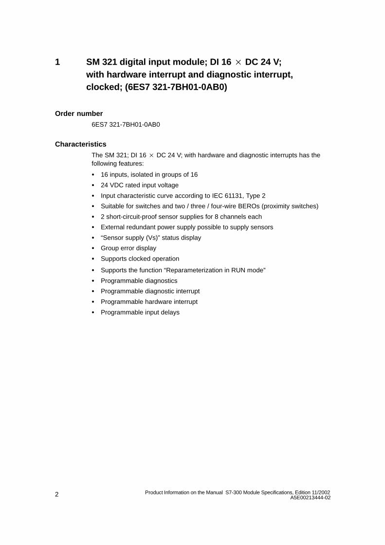
S7-300 Module Specifications, Edition 11/2002, (A5E00105505-02)
Introduction
The S7-300 product family has been enhanced and improved. This documentcontains details of the features and technical specifications of the modules.
Contents
Section Contents Page
1 SM 321 digital input module; DI 16 DC 24 V; with hardware interrupt and diagnostic interrupt, clocked; (6ES7 321-7BH01-0AB0)
2
2 SM 331 analog input module; AI 8 14 Bit High Speed, clocked; (6ES7 331-7HF00-0AB0)
14
3 Analog Output Module SM 332; AO 416 Bit, clocked; (6ES7332-7ND01–0AB0)
25
2 Product Information on the Manual S7-300 Module Specifications, Edition 11/2002A5E00213444-02
1 SM 321 digital input module; DI 16 DC 24 V; with hardware interrupt and diagnostic interrupt,clocked; (6ES7 321-7BH01-0AB0)
Order number
6ES7 321-7BH01-0AB0
Characteristics
The SM 321; DI 16 DC 24 V; with hardware and diagnostic interrupts has thefollowing features:
16 inputs, isolated in groups of 16
24 VDC rated input voltage
Input characteristic curve according to IEC 61131, Type 2
Suitable for switches and two / three / four-wire BEROs (proximity switches)
2 short-circuit-proof sensor supplies for 8 channels each
External redundant power supply possible to supply sensors
“Sensor supply (Vs)” status display
Group error display
Supports clocked operation
Supports the function “Reparameterization in RUN mode”
Programmable diagnostics
Programmable diagnostic interrupt
Programmable hardware interrupt
Programmable input delays
3Product Information on the Manual S7-300 Module Specifications, Edition 11/2002A5E00213444-02
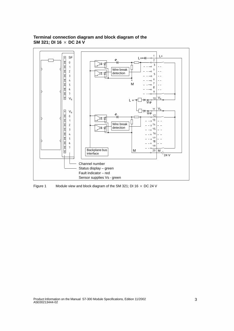
Terminal connection diagram and block diagram of the SM 321; DI 16 DC 24 V
Status display – greenChannel number
Backplane businterface
L+
M24 V
SF
Vs
Vs
Sensor supplies Vs - green
M
M
L+
Vs
Vs
L +
Fault indicator – red
Wire breakdetection
Wire breakdetection
Figure 1 Module view and block diagram of the SM 321; DI 16 DC 24 V
4 Product Information on the Manual S7-300 Module Specifications, Edition 11/2002A5E00213444-02
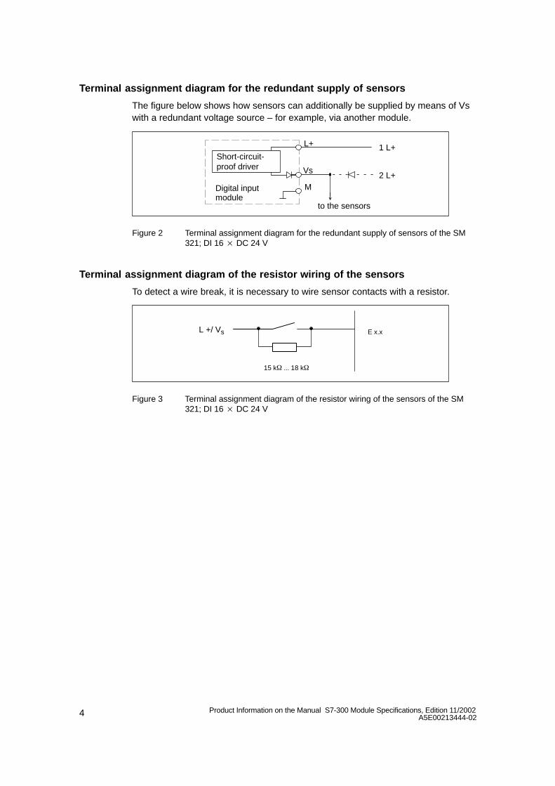
Terminal assignment diagram for the redundant supply of sensors
The figure below shows how sensors can additionally be supplied by means of Vswith a redundant voltage source – for example, via another module.
Vs
M
L+ 1 L+
2 L+
to the sensors
Digital inputmodule
Short-circuit-proof driver
Figure 2 Terminal assignment diagram for the redundant supply of sensors of the SM321; DI 16 DC 24 V
Terminal assignment diagram of the resistor wiring of the sensors
To detect a wire break, it is necessary to wire sensor contacts with a resistor.
L +/ Vs E x.x
15 k ... 18 k
Figure 3 Terminal assignment diagram of the resistor wiring of the sensors of the SM321; DI 16 DC 24 V
5Product Information on the Manual S7-300 Module Specifications, Edition 11/2002A5E00213444-02
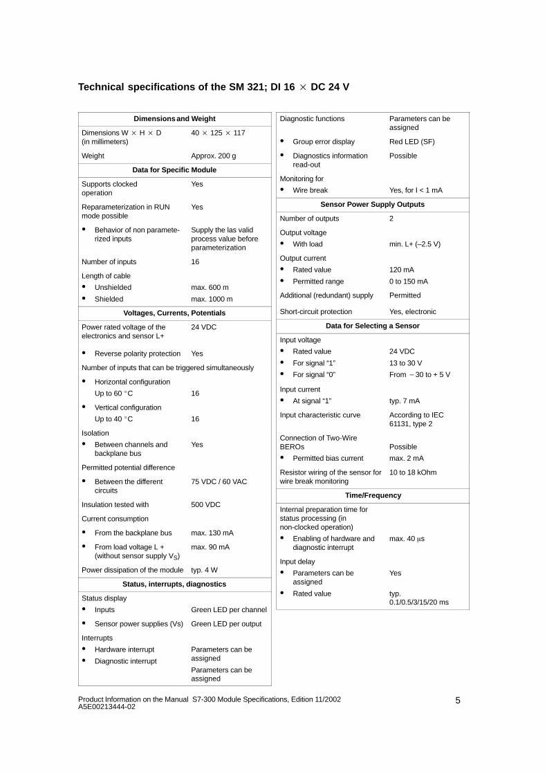
Technical specifications of the SM 321; DI 16 DC 24 V
Dimensions and Weight
Dimensions W H D (in millimeters)
40 125 117
Weight Approx. 200 g
Data for Specific Module
Supports clocked operation
Yes
Reparameterization in RUNmode possible
Yes
Behavior of non paramete-rized inputs
Supply the las validprocess value beforeparameterization
Number of inputs 16
Length of cable
Unshielded
Shielded
max. 600 m
max. 1000 m
Voltages, Currents, Potentials
Power rated voltage of theelectronics and sensor L+
24 VDC
Reverse polarity protection Yes
Number of inputs that can be triggered simultaneously
Horizontal configuration
Up to 60 C 16
Vertical configuration
Up to 40 C 16
Isolation
Between channels andbackplane bus
Yes
Permitted potential difference
Between the differentcircuits
75 VDC / 60 VAC
Insulation tested with 500 VDC
Current consumption
From the backplane bus max. 130 mA
From load voltage L +(without sensor supply VS)
max. 90 mA
Power dissipation of the module typ. 4 W
Status, interrupts, diagnostics
Status display
Inputs Green LED per channel
Sensor power supplies (Vs) Green LED per output
Interrupts
Hardware interrupt
Diagnostic interrupt
Parameters can beassigned
Parameters can beassigned
Diagnostic functions Parameters can beassigned
Group error display Red LED (SF)
Diagnostics informationread-out
Possible
Monitoring for
Wire break Yes, for I < 1 mA
Sensor Power Supply Outputs
Number of outputs 2
Output voltage
With load min. L+ (–2.5 V)
Output current
Rated value
Permitted range
120 mA
0 to 150 mA
Additional (redundant) supply Permitted
Short-circuit protection Yes, electronic
Data for Selecting a Sensor
Input voltage
Rated value
For signal “1”
For signal “0”
24 VDC
13 to 30 V
From 30 to + 5 V
Input current
At signal “1” typ. 7 mA
Input characteristic curve According to IEC61131, type 2
Connection of Two-WireBEROs
Permitted bias current
Possible
max. 2 mA
Resistor wiring of the sensor forwire break monitoring
10 to 18 kOhm
Time/Frequency
Internal preparation time forstatus processing (innon-clocked operation)
Enabling of hardware and diagnostic interrupt
max. 40 s
Input delay
Parameters can beassigned
Rated value
Yes
typ. 0.1/0.5/3/15/20 ms
6 Product Information on the Manual S7-300 Module Specifications, Edition 11/2002A5E00213444-02
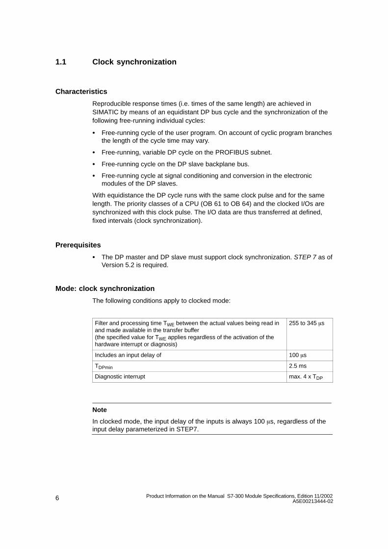
1.1 Clock synchronization
Characteristics
Reproducible response times (i.e. times of the same length) are achieved inSIMATIC by means of an equidistant DP bus cycle and the synchronization of thefollowing free-running individual cycles:
Free-running cycle of the user program. On account of cyclic program branchesthe length of the cycle time may vary.
Free-running, variable DP cycle on the PROFIBUS subnet.
Free-running cycle on the DP slave backplane bus.
Free-running cycle at signal conditioning and conversion in the electronicmodules of the DP slaves.
With equidistance the DP cycle runs with the same clock pulse and for the samelength. The priority classes of a CPU (OB 61 to OB 64) and the clocked I/Os aresynchronized with this clock pulse. The I/O data are thus transferred at defined,fixed intervals (clock synchronization).
Prerequisites
The DP master and DP slave must support clock synchronization. STEP 7 as ofVersion 5.2 is required.
Mode: clock synchronization
The following conditions apply to clocked mode:
Filter and processing time TWE between the actual values being read inand made available in the transfer buffer (the specified value for TWE applies regardless of the activation of thehardware interrupt or diagnosis)
255 to 345 s
Includes an input delay of 100 s
TDPmin 2.5 ms
Diagnostic interrupt max. 4 x TDP
Note
In clocked mode, the input delay of the inputs is always 100 s, regardless of theinput delay parameterized in STEP7.
7Product Information on the Manual S7-300 Module Specifications, Edition 11/2002A5E00213444-02
Further information
You will find further information on clock synchronization in the online help systemof STEP 7, in the manual ET 200M Distributed I/O System and in the manualClock Synchronization.
1.2 Parameterizing the SM 321; DI 16 DC 24 V
Parameter assignment
Section 3.3 of the reference manual describes how digital modules are generallyparameterized.
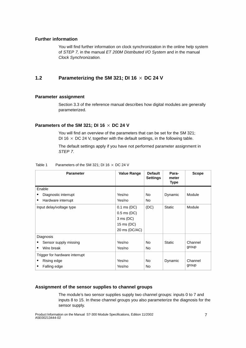
Parameters of the SM 321; DI 16 DC 24 V
You will find an overview of the parameters that can be set for the SM 321;DI 16 DC 24 V, together with the default settings, in the following table.
The default settings apply if you have not performed parameter assignment inSTEP 7.
Table 1 Parameters of the SM 321; DI 16 DC 24 V
Parameter Value Range DefaultSettings
Para-meterType
Scope
Enable
Diagnostic interrupt
Hardware interrupt
Yes/no
Yes/no
No
No
Dynamic Module
Input delay/voltage type 0.1 ms (DC)
0.5 ms (DC)
3 ms (DC)
15 ms (DC)
20 ms (DC/AC)
(DC) Static Module
Diagnosis
Sensor supply missing
Wire break
Yes/no
Yes/no
No
No
Static Channelgroup
Trigger for hardware interrupt
Rising edge
Falling edge
Yes/no
Yes/no
No
No
Dynamic Channelgroup
Assignment of the sensor supplies to channel groups
The module’s two sensor supplies supply two channel groups: inputs 0 to 7 andinputs 8 to 15. In these channel groups you also parameterize the diagnosis for thesensor supply.
8 Product Information on the Manual S7-300 Module Specifications, Edition 11/2002A5E00213444-02
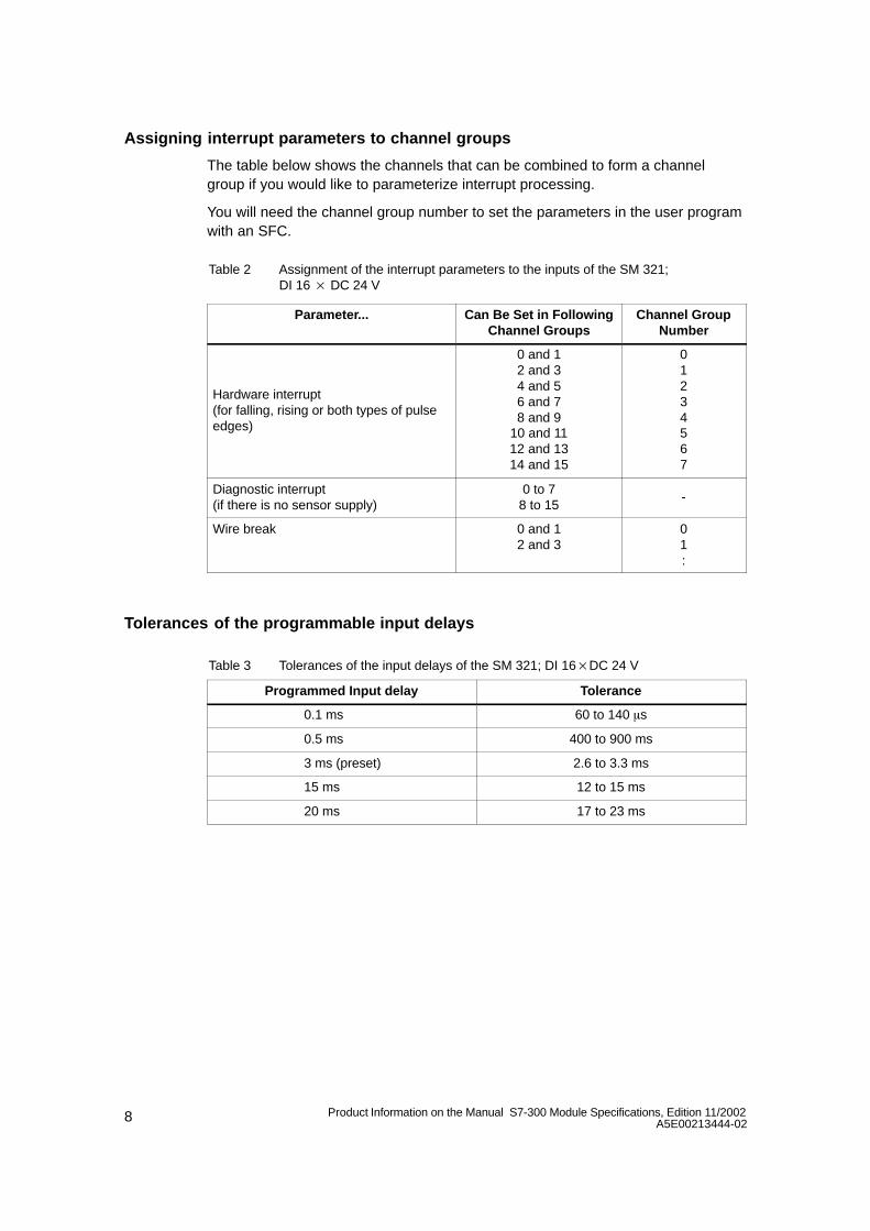
Assigning interrupt parameters to channel groups
The table below shows the channels that can be combined to form a channelgroup if you would like to parameterize interrupt processing.
You will need the channel group number to set the parameters in the user programwith an SFC.
Table 2 Assignment of the interrupt parameters to the inputs of the SM 321;DI 16 DC 24 V
Parameter... Can Be Set in FollowingChannel Groups
Channel GroupNumber
Hardware interrupt(for falling, rising or both types of pulseedges)
0 and 12 and 34 and 56 and 78 and 9
10 and 1112 and 1314 and 15
01234567
Diagnostic interrupt(if there is no sensor supply)
0 to 78 to 15
-
Wire break 0 and 12 and 3
01:
Tolerances of the programmable input delays
Table 3 Tolerances of the input delays of the SM 321; DI 16DC 24 V
Programmed Input delay Tolerance
0.1 ms 60 to 140 s
0.5 ms 400 to 900 ms
3 ms (preset) 2.6 to 3.3 ms
15 ms 12 to 15 ms
20 ms 17 to 23 ms
9Product Information on the Manual S7-300 Module Specifications, Edition 11/2002A5E00213444-02
1.3 Behavior and diagnostics of the SM 321; DI 16 DC 24 V
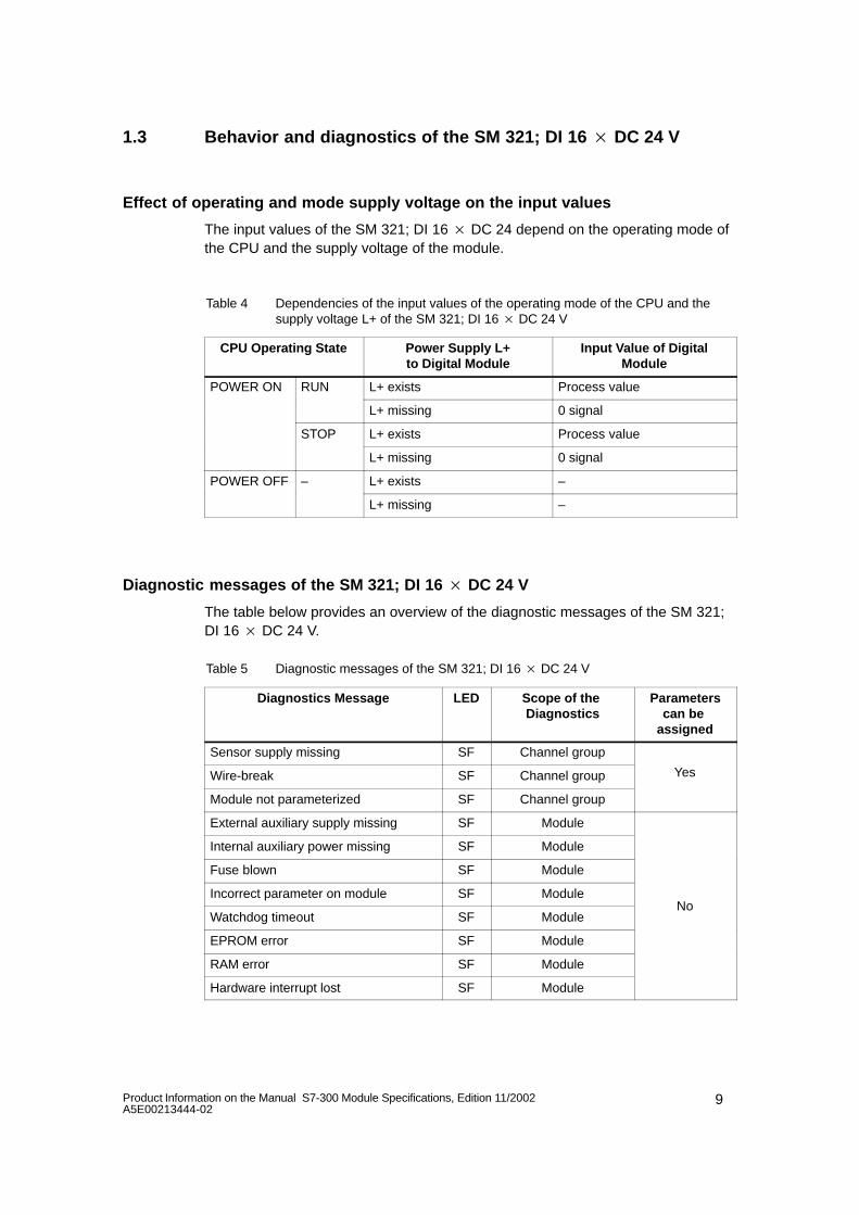
Effect of operating and mode supply voltage on the input values
The input values of the SM 321; DI 16 DC 24 depend on the operating mode ofthe CPU and the supply voltage of the module.
Table 4 Dependencies of the input values of the operating mode of the CPU and thesupply voltage L+ of the SM 321; DI 16 DC 24 V
CPU Operating State Power Supply L+to Digital Module
Input Value of DigitalModule
POWER ON RUN L+ exists Process value
L+ missing 0 signal
STOP L+ exists Process value
L+ missing 0 signal
POWER OFF – L+ exists –
L+ missing –
Diagnostic messages of the SM 321; DI 16 DC 24 V
The table below provides an overview of the diagnostic messages of the SM 321;DI 16 DC 24 V.
Table 5 Diagnostic messages of the SM 321; DI 16 DC 24 V
Diagnostics Message LED Scope of the Diagnostics
Parameterscan be
assigned
Sensor supply missing SF Channel group
Wire-break SF Channel group Yes
Module not parameterized SF Channel group
External auxiliary supply missing SF Module
Internal auxiliary power missing SF Module
Fuse blown SF Module
Incorrect parameter on module SF Module
Watchdog timeout SF ModuleNo
EPROM error SF Module
RAM error SF Module
Hardware interrupt lost SF Module
10 Product Information on the Manual S7-300 Module Specifications, Edition 11/2002A5E00213444-02
Note
A prerequisite for detecting the errors indicated by programmable diagnosticmessages is that you have assigned parameters to the digital module accordinglyin STEP 7.
Behavior upon failure of the supply voltage
The failure of the supply voltage of the SM 321; DI 16 DC 24 is always indicatedby the SF LED on the module. Furthermore, this information is made available onthe module.
The input value is initially held for 20 to 40 ms before the 0 signal is transferred tothe CPU. Supply voltage dips < 20 ms do not change the process value (see Table4).
Triggering of the diagnostic interrupt depends on the parameter assignment (seeSection 1.4).
Failure of the supply voltage with redundant incoming supply for the sensorsupply
Note
If an external redundant source is applied simultaneously to the sensor supply(Vs), a failure in the internal sensor supply causes a failure of the internal and/orexternal sensor supply and/or a blown fuse to be indicated instead of a regularsensor supply failure.
Short-circuit of sensor supply Vs
Irrespective of the parameter assignment, the corresponding Vs LED goes out if ashort-circuit of the sensor supply Vs occurs.
11Product Information on the Manual S7-300 Module Specifications, Edition 11/2002A5E00213444-02
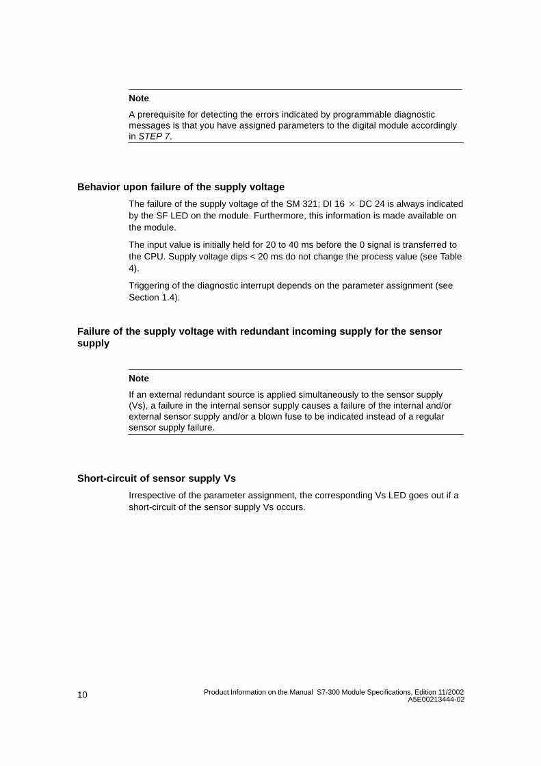
Causes of errors and remedial action
Table 6 Diagnostic messages of the SM 321; DI 16 DC 24 V, causes of errors and remedial action
Diagnostics Message
Possible Error Cause Remedy
Missing sensor supply Overload of sensor supply Eliminate overload
Short circuit of sensor supply to M Eliminate short circuit
External auxiliarysupply missing
Power supply L+ to module missing Feed supply L+
Internal auxiliary Power supply L+ to module missing Feed supply L+supply missing
Fuse in module defective Replace module
Fuse blown Fuse in module defective Replace module
Incorrect parametersin module
One parameter or the combination ofparameters is not plausible
Reassign module parameter
Time monitoringtriggered (watch dog)
Temporary high electromagneticinterference
Eliminate interference
Module defective Replace module
EPROM error Temporary high electromagneticinterference
Eliminate interference and switch on/offpower supply of CPU
Module defective Replace module
RAM error Temporary high electromagneticinterference
Eliminate interference and switch on/offpower supply of CPU
Module defective Replace module
Hardware interrupt lost The module cannot send an interrupt,since the previous interrupt was notacknowledged; possible configurationerror
Change interrupt processing in CPUand reconfigure module parameters, ifrequired
The error continues until the module isconfigured with new parameters
Module notparameterized
Problem at startup Reassign module parameter
12 Product Information on the Manual S7-300 Module Specifications, Edition 11/2002A5E00213444-02
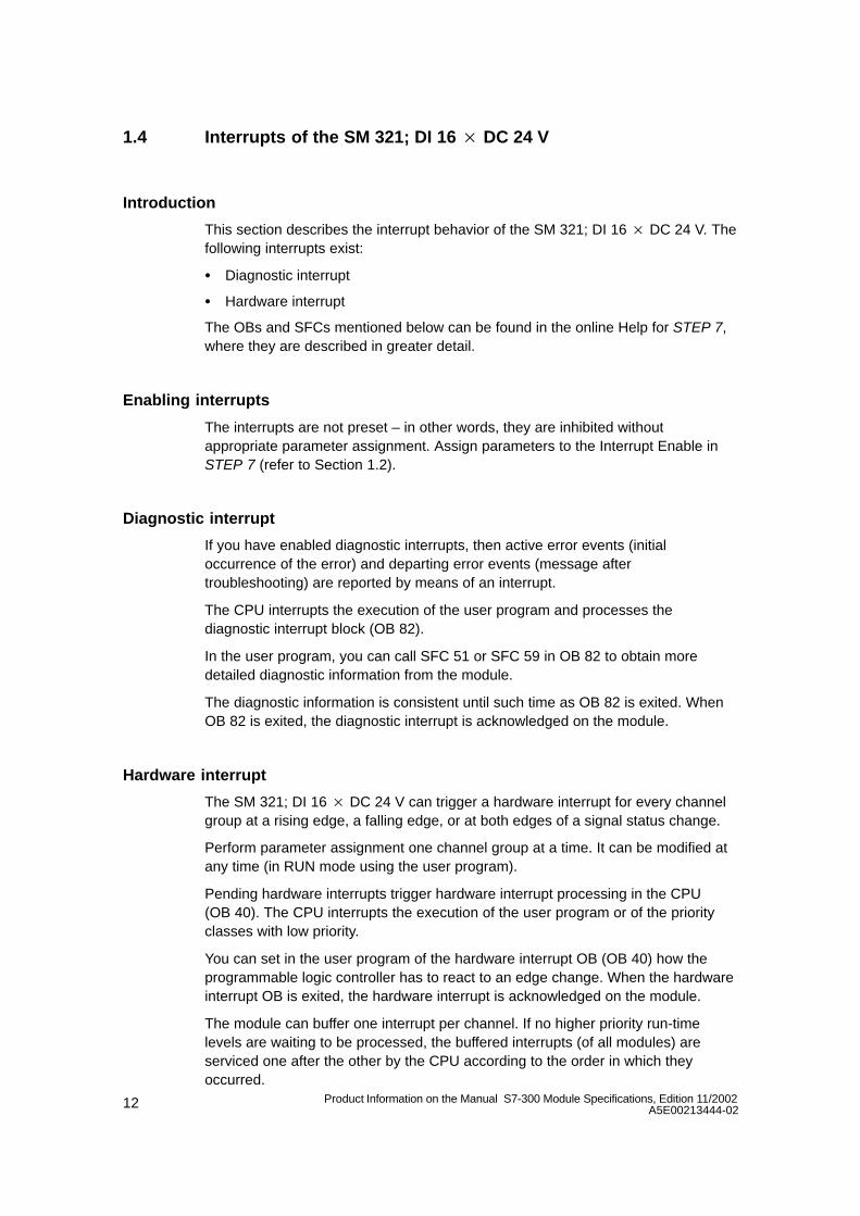
1.4 Interrupts of the SM 321; DI 16 DC 24 V
Introduction
This section describes the interrupt behavior of the SM 321; DI 16 DC 24 V. Thefollowing interrupts exist:
Diagnostic interrupt
Hardware interrupt
The OBs and SFCs mentioned below can be found in the online Help for STEP 7,where they are described in greater detail.
Enabling interrupts
The interrupts are not preset – in other words, they are inhibited withoutappropriate parameter assignment. Assign parameters to the Interrupt Enable inSTEP 7 (refer to Section 1.2).
Diagnostic interrupt
If you have enabled diagnostic interrupts, then active error events (initialoccurrence of the error) and departing error events (message aftertroubleshooting) are reported by means of an interrupt.
The CPU interrupts the execution of the user program and processes thediagnostic interrupt block (OB 82).
In the user program, you can call SFC 51 or SFC 59 in OB 82 to obtain moredetailed diagnostic information from the module.
The diagnostic information is consistent until such time as OB 82 is exited. WhenOB 82 is exited, the diagnostic interrupt is acknowledged on the module.
Hardware interrupt
The SM 321; DI 16 DC 24 V can trigger a hardware interrupt for every channelgroup at a rising edge, a falling edge, or at both edges of a signal status change.
Perform parameter assignment one channel group at a time. It can be modified atany time (in RUN mode using the user program).
Pending hardware interrupts trigger hardware interrupt processing in the CPU(OB 40). The CPU interrupts the execution of the user program or of the priorityclasses with low priority.
You can set in the user program of the hardware interrupt OB (OB 40) how theprogrammable logic controller has to react to an edge change. When the hardwareinterrupt OB is exited, the hardware interrupt is acknowledged on the module.
The module can buffer one interrupt per channel. If no higher priority run-timelevels are waiting to be processed, the buffered interrupts (of all modules) areserviced one after the other by the CPU according to the order in which theyoccurred.
13Product Information on the Manual S7-300 Module Specifications, Edition 11/2002A5E00213444-02
Hardware interrupt lost
In an interrupt has been buffered for a channel and another interrupt occurs on thatchannel before it has been processed by the CPU, a diagnostic interrupt “hardwareinterrupt lost” is triggered.
More interrupts on this channel are not acquired until processing of the interruptbuffered on this channel has been executed.
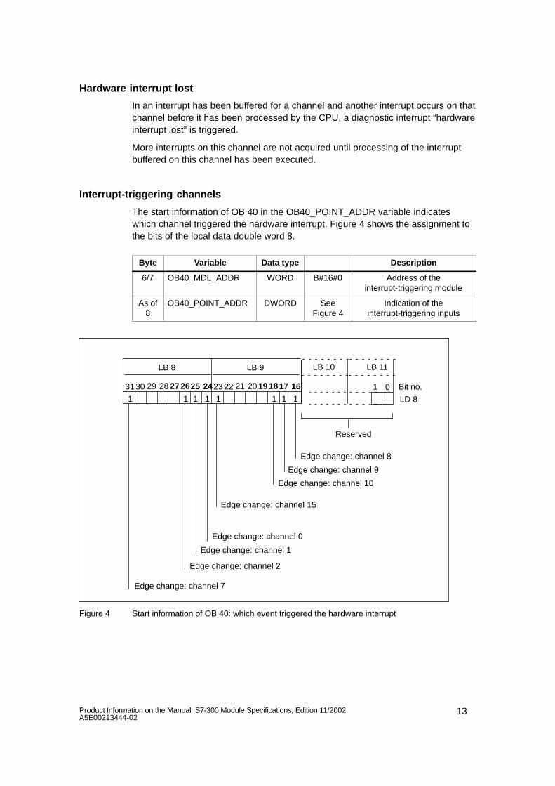
Interrupt-triggering channels
The start information of OB 40 in the OB40_POINT_ADDR variable indicateswhich channel triggered the hardware interrupt. Figure 4 shows the assignment tothe bits of the local data double word 8.
Byte Variable Data type Description
6/7 OB40_MDL_ADDR WORD B#16#0 Address of theinterrupt-triggering module
As of8
OB40_POINT_ADDR DWORD SeeFigure 4
Indication of theinterrupt-triggering inputs
1Bit no.3130 29 28 27 26
LD 81
LB 8
25 24
Edge change: channel 2
Edge change: channel 0
Edge change: channel 7
LB 11
01
Edge change: channel 1
11
LB 10
1
23 22 21 20 19 18
1
LB 9
17 16
11
Edge change: channel 10
Edge change: channel 8
Edge change: channel 15
Edge change: channel 9
Reserved
Figure 4 Start information of OB 40: which event triggered the hardware interrupt
14 Product Information on the Manual S7-300 Module Specifications, Edition 11/2002A5E00213444-02
2 Analog input module SM 331; AI 8 14 Bit High Speed,clocked; (6ES7 331-7HF00-0AB0)
Order number6ES7 331-7HF00-0AB0
CharacteristicsThe SM 331; AI 8 14 Bit High Speed has the following features:
8 inputs in 4 channel groups
Measured-value resolution 13 bits + sign
Measuring method selectable per channel group:
– Voltage
– Current
Arbitrary measuring range selection per channel group
Programmable hardware interrupt
Programmable diagnostics
Programmable diagnostic interrupt
Supports clocked operation
Isolated against the backplane bus interface
Isolated from the load voltage (not in the case of the 2-wire transmitter)
15Product Information on the Manual S7-300 Module Specifications, Edition 11/2002A5E00213444-02
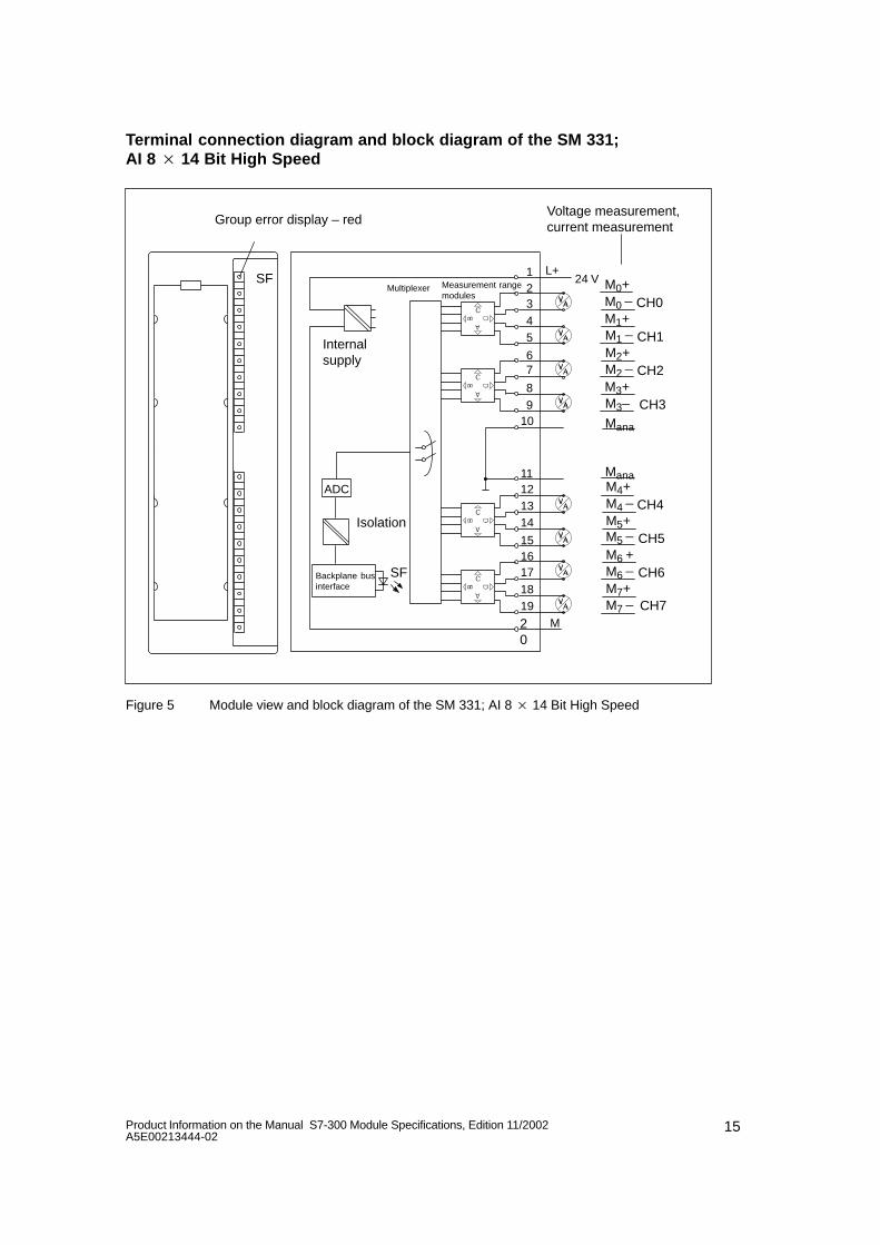
Terminal connection diagram and block diagram of the SM 331; AI 8 14 Bit High Speed
M3–
Mana
Group error display – redVoltage measurement,current measurement
M0+M0
M1+
Mana
SF
Internal supply
M
L+Multiplexer Measurement range
modules
ADC
Isolation
Backplane businterface
SF
CH0
CH1M1
M2+CH2M2
M3+CH3
M4+M4
M5+CH4
CH5M5
M6 +CH6M6
M7+CH7M7
24 V12345
67
98
10
11121314
1516171819
20
Figure 5 Module view and block diagram of the SM 331; AI 8 14 Bit High Speed
16 Product Information on the Manual S7-300 Module Specifications, Edition 11/2002A5E00213444-02
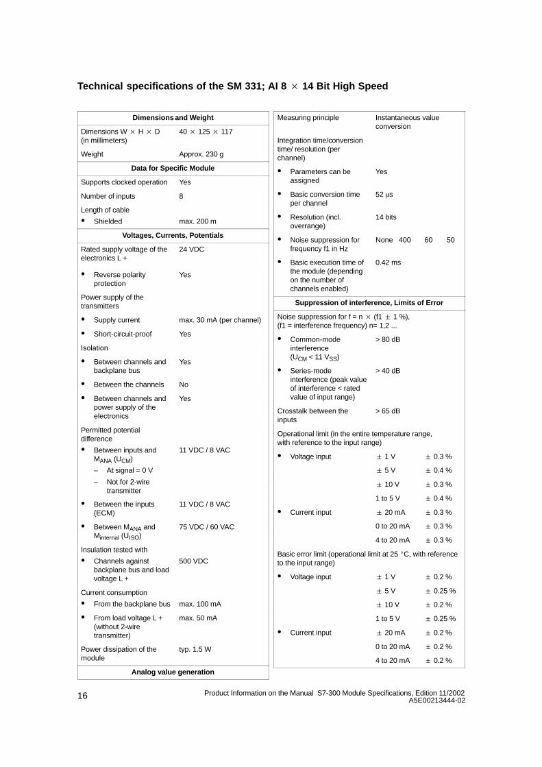
Technical specifications of the SM 331; AI 8 14 Bit High Speed
Dimensions and Weight
Dimensions W H D (in millimeters)
40 125 117
Weight Approx. 230 g
Data for Specific Module
Supports clocked operation Yes
Number of inputs 8
Length of cable
Shielded max. 200 m
Voltages, Currents, Potentials
Rated supply voltage of theelectronics L +
24 VDC
Reverse polarityprotection
Yes
Power supply of thetransmitters
Supply current max. 30 mA (per channel)
Short-circuit-proof Yes
Isolation
Between channels andbackplane bus
Yes
Between the channels No
Between channels andpower supply of theelectronics
Yes
Permitted potentialdifference
Between inputs andMANA (UCM)
– At signal = 0 V
– Not for 2-wiretransmitter
11 VDC / 8 VAC
Between the inputs(ECM)
11 VDC / 8 VAC
Between MANA andMinternal (UISO)
75 VDC / 60 VAC
Insulation tested with
Channels againstbackplane bus and loadvoltage L +
500 VDC
Current consumption
From the backplane bus max. 100 mA
From load voltage L +(without 2-wiretransmitter)
max. 50 mA
Power dissipation of themodule
typ. 1.5 W
Analog value generation
Measuring principle Instantaneous valueconversion
Integration time/conversiontime/ resolution (perchannel)
Parameters can beassigned
Yes
Basic conversion timeper channel
52 s
Resolution (incl.overrange)
14 bits
Noise suppression forfrequency f1 in Hz
None 400 60 50
Basic execution time ofthe module (dependingon the number ofchannels enabled)
0.42 ms
Suppression of interference, Limits of Error
Noise suppression for f = n (f1 1 %),(f1 = interference frequency) n= 1,2 ...
Common-modeinterference(UCM < 11 VSS)
> 80 dB
Series-modeinterference (peak valueof interference < ratedvalue of input range)
> 40 dB
Crosstalk between theinputs
> 65 dB
Operational limit (in the entire temperature range, with reference to the input range)
Voltage input 1 V 0.3 %
5 V 0.4 %
10 V 0.3 %
1 to 5 V 0.4 %
Current input 20 mA 0.3 %
0 to 20 mA 0.3 %
4 to 20 mA 0.3 %
Basic error limit (operational limit at 25 C, with referenceto the input range)
Voltage input 1 V 0.2 %
5 V 0.25 %
10 V 0.2 %
1 to 5 V 0.25 %
Current input 20 mA 0.2 %
0 to 20 mA 0.2 %
4 to 20 mA 0.2 %
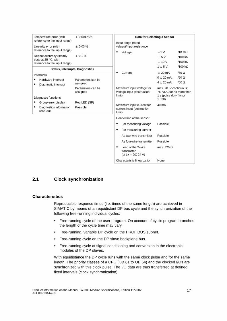
17Product Information on the Manual S7-300 Module Specifications, Edition 11/2002A5E00213444-02
Temperature error (withreference to the input range)
0.004 %/K
Linearity error (withreference to the input range)
0.03 %
Repeat accuracy (steadystate at 25 C, withreference to the input range)
0.1 %
Status, Interrupts, Diagnostics
Interrupts
Hardware interrupt
Diagnostic interrupt
Parameters can beassigned
Parameters can beassigned
Diagnostic functions
Group error display
Diagnostics informationread-out
Red LED (SF)
Possible
Data for Selecting a Sensor
Input range (ratedvalues)/Input resistance
Voltage 1 V
5 V
10 V
1 to 5 V;
/10 MΩ/100 kΩ/100 kΩ/100 kΩ
Current 20 mA
0 to 20 mA;
4 to 20 mA:
/50 Ω/50 Ω/50 Ω
Maximum input voltage forvoltage input (destructionlimit)
max. 20 V continuous;75 VDC for no more than1 s (pulse duty factor 1 : 20)
Maximum input current forcurrent input (destructionlimit)
40 mA
Connection of the sensor
For measuring voltage Possible
For measuring current
As two-wire transmitter Possible
As four-wire transmitter Possible
Load of the 2-wiretransmitter (at L+ = DC 24 V)
max. 820 Ω
Characteristic linearization None
2.1 Clock synchronization
Characteristics
Reproducible response times (i.e. times of the same length) are achieved inSIMATIC by means of an equidistant DP bus cycle and the synchronization of thefollowing free-running individual cycles:
Free-running cycle of the user program. On account of cyclic program branchesthe length of the cycle time may vary.
Free-running, variable DP cycle on the PROFIBUS subnet.
Free-running cycle on the DP slave backplane bus.
Free-running cycle at signal conditioning and conversion in the electronicmodules of the DP slaves.
With equidistance the DP cycle runs with the same clock pulse and for the samelength. The priority classes of a CPU (OB 61 to OB 64) and the clocked I/Os aresynchronized with this clock pulse. The I/O data are thus transferred at defined,fixed intervals (clock synchronization).
18 Product Information on the Manual S7-300 Module Specifications, Edition 11/2002A5E00213444-02
Prerequisites
The DP master and DP slave must support clock synchronization. STEP 7 as ofVersion 5.2 is required.
Mode: clock synchronization
The following conditions apply to clocked mode:
Filter and processing time TWE between the actual values being read inand made available in the transfer buffer (the specified value for T WE applies regardless of the activation of thehardware interrupt or diagnosis)
516 to 606 s
Includes an input delay of 80 s
TDPmin 3.5 ms
Diagnostic interrupt max. 4 x TDP
Note
In clocked mode, the integration time for the module is always set to “none” or“interference frequency”, regardless of the parameter assignment in STEP 7.Hardware interrupt functionality is not possible in clocked mode.
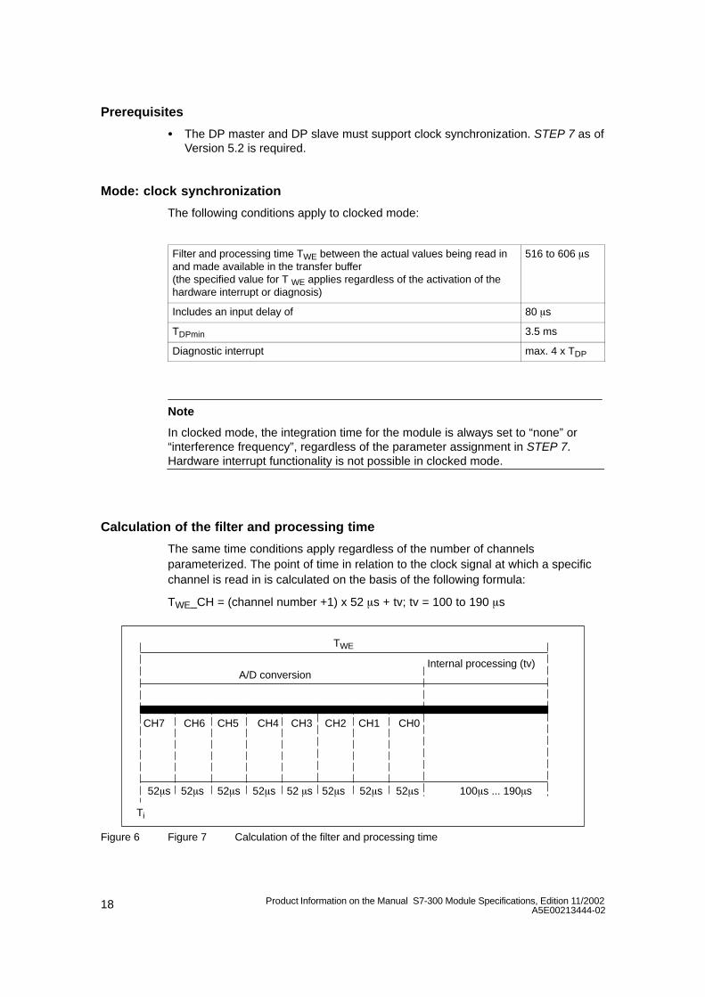
Calculation of the filter and processing time
The same time conditions apply regardless of the number of channelsparameterized. The point of time in relation to the clock signal at which a specificchannel is read in is calculated on the basis of the following formula:
TWE_CH = (channel number +1) x 52 s + tv; tv = 100 to 190 s
CH7 CH6 CH5 CH4 CH3 CH2 CH1 CH0
52s 52s 52s 52 s52s 52s 52s 52s 100s ... 190s
A/D conversionInternal processing (tv)
TWE
Ti
Figure 6 Figure 7 Calculation of the filter and processing time
19Product Information on the Manual S7-300 Module Specifications, Edition 11/2002A5E00213444-02
Explanation of functioning in clocked mode
At Ti starts AD conversion for channel 7 and saves its result internally. Channels 6to 0 are then converted sequentially in the same way at intervals of 52 s. After anadditional internal processing time, the results of all the converted channels aremade available on the backplane bus to be picked up by the CPU.
Further information
You will find further information on clock synchronization in the online help systemof STEP 7, in the manual ET 200M Distributed I/O System and in the manualClock Synchronization.
20 Product Information on the Manual S7-300 Module Specifications, Edition 11/2002A5E00213444-02
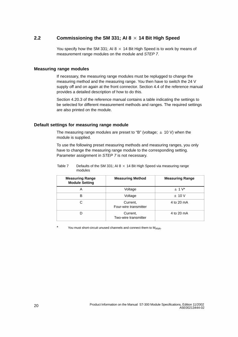
2.2 Commissioning the SM 331; AI 8 14 Bit High Speed
You specify how the SM 331; AI 8 14 Bit High Speed is to work by means ofmeasurement range modules on the module and STEP 7.
Measuring range modules
If necessary, the measuring range modules must be replugged to change themeasuring method and the measuring range. You then have to switch the 24 Vsupply off and on again at the front connector. Section 4.4 of the reference manualprovides a detailed description of how to do this.
Section 4.20.3 of the reference manual contains a table indicating the settings tobe selected for different measurement methods and ranges. The required settingsare also printed on the module.
Default settings for measuring range module
The measuring range modules are preset to “B” (voltage; 10 V) when themodule is supplied.
To use the following preset measuring methods and measuring ranges, you onlyhave to change the measuring range module to the corresponding setting.Parameter assignment in STEP 7 is not necessary.
Table 7 Defaults of the SM 331; AI 8 14 Bit High Speed via measuring rangemodules
Measuring Range Module Setting
Measuring Method Measuring Range
A Voltage 1 V*
B Voltage 10 V
C Current,Four-wire transmitter
4 to 20 mA
D Current,Two-wire transmitter
4 to 20 mA
* You must short-circuit unused channels and connect them to MANA.
21Product Information on the Manual S7-300 Module Specifications, Edition 11/2002A5E00213444-02
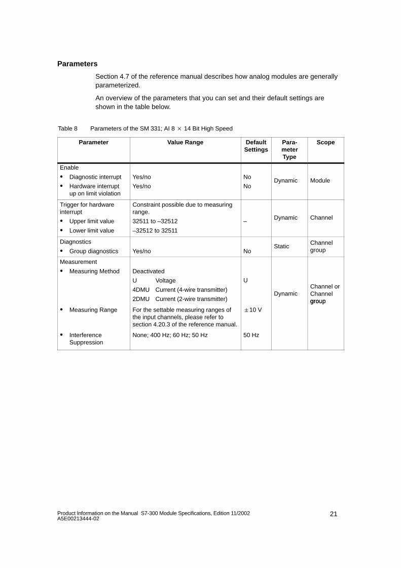
Parameters
Section 4.7 of the reference manual describes how analog modules are generallyparameterized.
An overview of the parameters that you can set and their default settings areshown in the table below.
Table 8 Parameters of the SM 331; AI 8 14 Bit High Speed
Parameter Value Range DefaultSettings
Para-meterType
Scope
Enable
Diagnostic interrupt
Hardware interruptup on limit violation
Yes/no
Yes/no
No
NoDynamic Module
Trigger for hardwareinterrupt
Upper limit value
Lower limit value
Constraint possible due to measuringrange.
32511 to –32512
–32512 to 32511
–Dynamic Channel
Diagnostics
Group diagnostics Yes/no NoStatic
Channelgroup
Measurement
Measuring Method Deactivated
U Voltage
4DMU Current (4-wire transmitter)
2DMU Current (2-wire transmitter)
U
DynamicChannel orChannelgroup
Measuring Range For the settable measuring ranges ofthe input channels, please refer tosection 4.20.3 of the reference manual.
10 Vgroup
InterferenceSuppression
None; 400 Hz; 60 Hz; 50 Hz 50 Hz
22 Product Information on the Manual S7-300 Module Specifications, Edition 11/2002A5E00213444-02
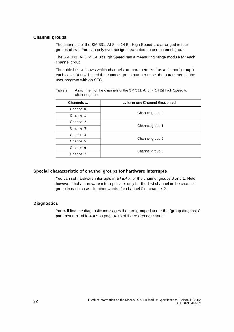
Channel groups
The channels of the SM 331; AI 8 14 Bit High Speed are arranged in fourgroups of two. You can only ever assign parameters to one channel group.
The SM 331; AI 8 14 Bit High Speed has a measuring range module for eachchannel group.
The table below shows which channels are parameterized as a channel group ineach case. You will need the channel group number to set the parameters in theuser program with an SFC.
Table 9 Assignment of the channels of the SM 331; AI 8 14 Bit High Speed to channel groups
Channels ... ... form one Channel Group each
Channel 0
Channel 1Channel group 0
Channel 2
Channel 3Channel group 1
Channel 4
Channel 5Channel group 2
Channel 6
Channel 7Channel group 3
Special characteristic of channel groups for hardware interrupts
You can set hardware interrupts in STEP 7 for the channel groups 0 and 1. Note,however, that a hardware interrupt is set only for the first channel in the channelgroup in each case – in other words, for channel 0 or channel 2.
Diagnostics
You will find the diagnostic messages that are grouped under the “group diagnosis”parameter in Table 4-47 on page 4-73 of the reference manual.
23Product Information on the Manual S7-300 Module Specifications, Edition 11/2002A5E00213444-02
2.3 Measuring methods and measuring ranges of the SM 331; AI 8 14 Bit High Speed
Measuring Methods
You can set the following measuring methods for the input channels:
Voltage measurement
Current measurement
You perform the setting by means of the measuring range modules on the moduleand with the “measuring method” parameter in STEP 7.
Unused Channels
You must short-circuit unused channels and connect them to MANA. In this way,you obtain an optimum interference immunity for the analog input module. Set the“measuring method” parameter for unused channels to “disabled”.
Special characteristics of unused channels for some measuring ranges
Since configured inputs can remain unused because of the channel groupgeneration, you must take note of the following special characteristics of theseinputs to enable the diagnostic functions on the used channels.
Measuring range 1 to 5 V: parallel connection of the unused input with theused input of the same channel group.
Current measurement, 2-wire transmitter:two channel wiring options.
a) Leave the unused input open and do not enable diagnostics for this channel group. Otherwise, if diagnostics are enabled, the analogmodule triggers a single diagnostic interrupt and the SF LED of theanalog module comes on.
b) Connect the unused input with a resistance of 1.5 to 3.3 k. You maythen enable diagnostics for this channel group.
Current measurement 4 to 20 mA, 4-wire transmitter: series connection ofthe unused input with the input of the same channel group.
24 Product Information on the Manual S7-300 Module Specifications, Edition 11/2002A5E00213444-02
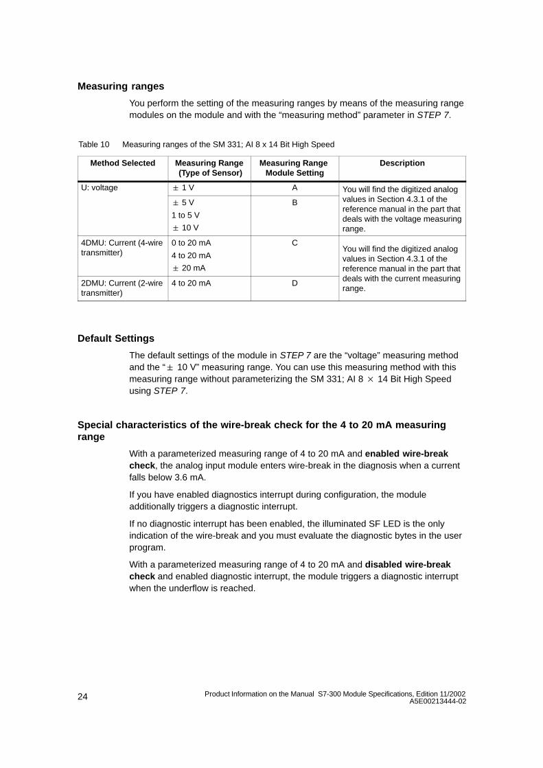
Measuring ranges
You perform the setting of the measuring ranges by means of the measuring rangemodules on the module and with the “measuring method” parameter in STEP 7.
Table 10 Measuring ranges of the SM 331; AI 8 x 14 Bit High Speed
Method Selected Measuring Range (Type of Sensor)
Measuring Range Module Setting
Description
U: voltage 1 V A You will find the digitized analog
5 V
1 to 5 V
10 V
B values in Section 4.3.1 of thereference manual in the part thatdeals with the voltage measuringrange.
4DMU: Current (4-wiretransmitter)
0 to 20 mA
4 to 20 mA
20 mA
CYou will find the digitized analogvalues in Section 4.3.1 of thereference manual in the part that
2DMU: Current (2-wiretransmitter)
4 to 20 mA D deals with the current measuringrange.
Default Settings
The default settings of the module in STEP 7 are the “voltage” measuring methodand the “ 10 V” measuring range. You can use this measuring method with thismeasuring range without parameterizing the SM 331; AI 8 14 Bit High Speedusing STEP 7.
Special characteristics of the wire-break check for the 4 to 20 mA measuringrange
With a parameterized measuring range of 4 to 20 mA and enabled wire-breakcheck, the analog input module enters wire-break in the diagnosis when a currentfalls below 3.6 mA.
If you have enabled diagnostics interrupt during configuration, the moduleadditionally triggers a diagnostic interrupt.
If no diagnostic interrupt has been enabled, the illuminated SF LED is the onlyindication of the wire-break and you must evaluate the diagnostic bytes in the userprogram.
With a parameterized measuring range of 4 to 20 mA and disabled wire-breakcheck and enabled diagnostic interrupt, the module triggers a diagnostic interruptwhen the underflow is reached.
25Product Information on the Manual S7-300 Module Specifications, Edition 11/2002A5E00213444-02
3 Analog Output Module SM 332; AO 4 16 Bit; clocked;(6ES7 332-7ND01-0AB0)
Order number
6ES7 332-7ND01-0AB0
Characteristic
The Analog Output Module SM 332; AO 4 × 16 Bit has the following characteristicfeatures:
4 outputs in 4 channel groups
Individual output channels can be programmed as
– voltage outputs
– current outputs
Resolution of 16 bits
Supports clocked operation
Supports the function “Reparameterization in RUN mode”
Programmable diagnostics
Programmable diagnostic interrupt
Programmable substitute value output
Galvanic Isolation between:
– backplane bus interface and analog output channels
– the different analog output channels
– analog output and L+, M
– backplane bus interface and L+, M
26 Product Information on the Manual S7-300 Module Specifications, Edition 11/2002A5E00213444-02
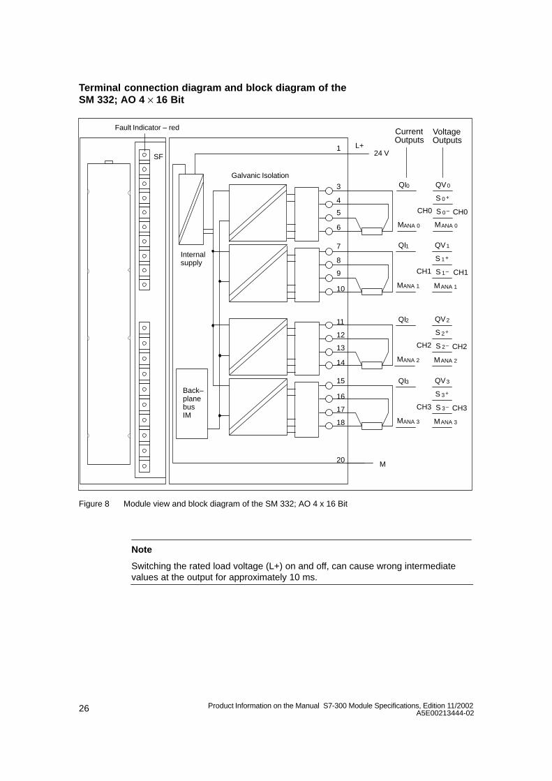
Terminal connection diagram and block diagram of the SM 332; AO 4 × 16 Bit
SF
QI0Galvanic Isolation
CH0 CH0
CurrentOutputs
VoltageOutputs
MANA 0
QV0
S 0 +
S 0 –
MANA 0
Fault Indicator – red
QI1
CH1 CH1
MANA 1
QV1
S 1+
S 1–
MANA 1
QI2
CH2 CH2
MANA 2
QV2
S 2+
S 2–
MANA 2
QI3
CH3 CH3
MANA 3
QV3
S 3+
S 3–
MANA 3
L+24 V
M
1
3
4
5
6
7
8
9
10
11
12
13
14
15
16
17
18
20
Internalsupply
Back–planebusIM
Figure 8 Module view and block diagram of the SM 332; AO 4 x 16 Bit
Note
Switching the rated load voltage (L+) on and off, can cause wrong intermediatevalues at the output for approximately 10 ms.
27Product Information on the Manual S7-300 Module Specifications, Edition 11/2002A5E00213444-02
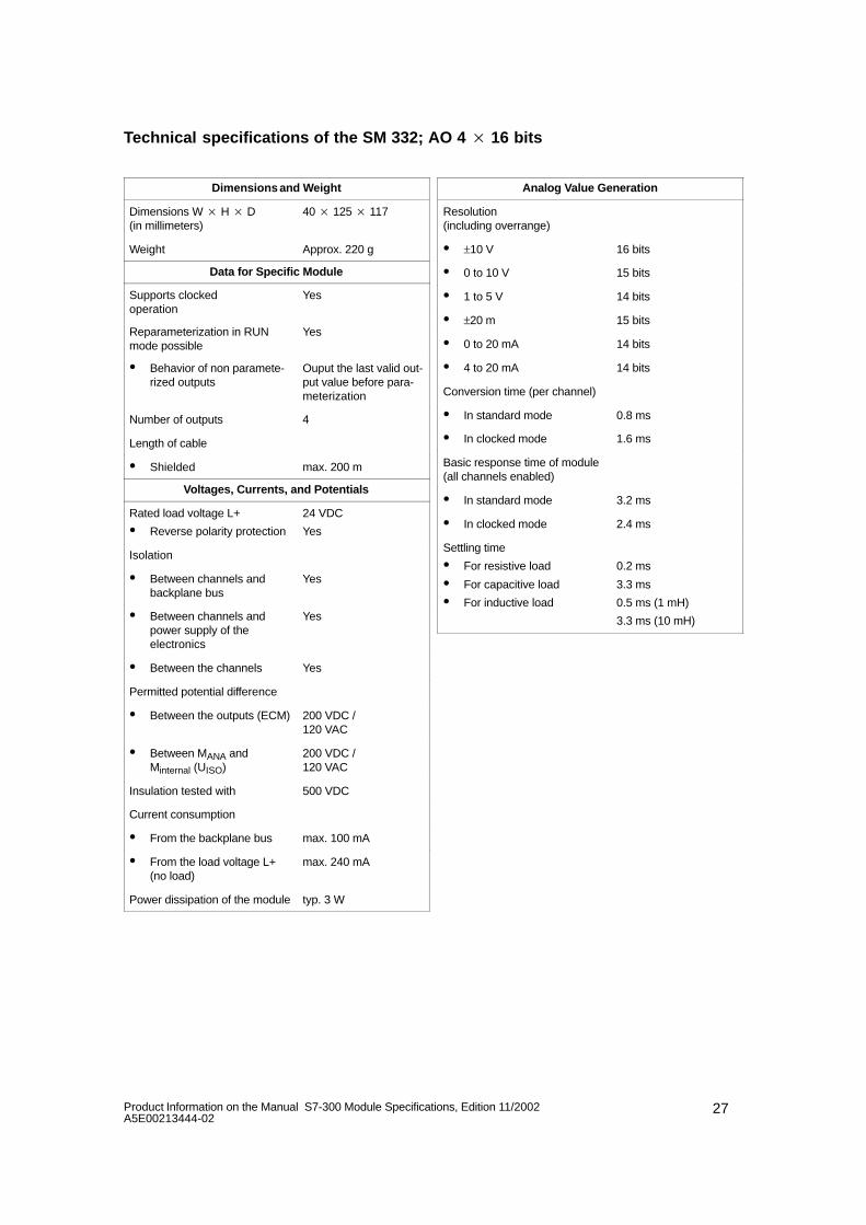
Technical specifications of the SM 332; AO 4 16 bits
Dimensions and Weight
Dimensions W H D (in millimeters)
40 125 117
Weight Approx. 220 g
Data for Specific Module
Supports clocked operation
Yes
Reparameterization in RUNmode possible
Yes
Behavior of non paramete-rized outputs
Ouput the last valid out-put value before para-meterization
Number of outputs 4
Length of cable
Shielded max. 200 m
Voltages, Currents, and Potentials
Rated load voltage L+
Reverse polarity protection
24 VDC
Yes
Isolation
Between channels andbackplane bus
Yes
Between channels andpower supply of theelectronics
Yes
Between the channels Yes
Permitted potential difference
Between the outputs (ECM) 200 VDC / 120 VAC
Between MANA andMinternal (UISO)
200 VDC / 120 VAC
Insulation tested with 500 VDC
Current consumption
From the backplane bus max. 100 mA
From the load voltage L+(no load)
max. 240 mA
Power dissipation of the module typ. 3 W
Analog Value Generation
Resolution (including overrange)
±10 V 16 bits
0 to 10 V 15 bits
1 to 5 V 14 bits
±20 m 15 bits
0 to 20 mA 14 bits
4 to 20 mA 14 bits
Conversion time (per channel)
In standard mode 0.8 ms
In clocked mode 1.6 ms
Basic response time of module(all channels enabled)
In standard mode 3.2 ms
In clocked mode 2.4 ms
Settling time
For resistive load
For capacitive load
For inductive load
0.2 ms
3.3 ms
0.5 ms (1 mH)
3.3 ms (10 mH)
28 Product Information on the Manual S7-300 Module Specifications, Edition 11/2002A5E00213444-02
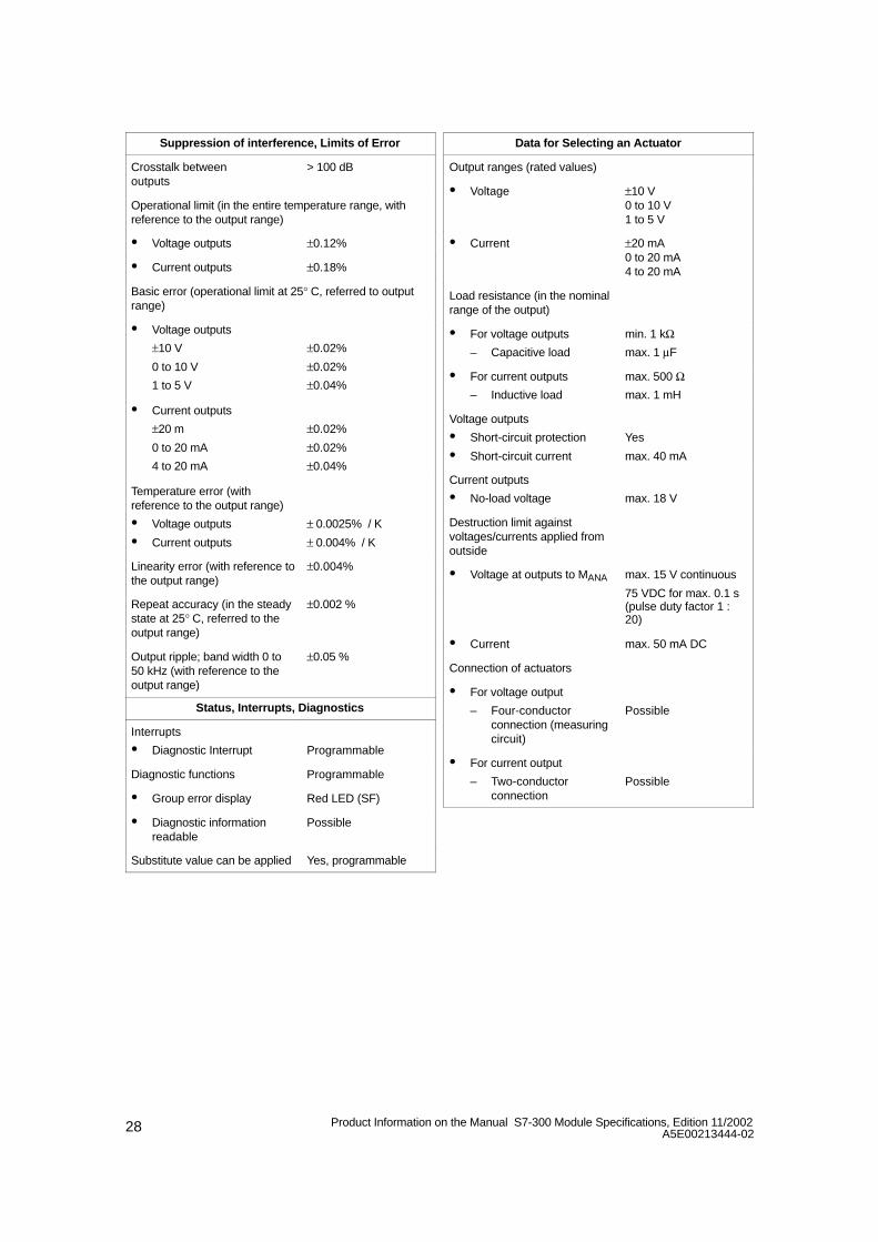
Suppression of interference, Limits of Error
Crosstalk between outputs
> 100 dB
Operational limit (in the entire temperature range, withreference to the output range)
Voltage outputs ±0.12%
Current outputs ±0.18%
Basic error (operational limit at 25° C, referred to outputrange)
Voltage outputs
±10 V
0 to 10 V
1 to 5 V
±0.02%
±0.02%
±0.04%
Current outputs
±20 m
0 to 20 mA
4 to 20 mA
±0.02%
±0.02%
±0.04%
Temperature error (withreference to the output range)
Voltage outputs
Current outputs
± 0.0025% / K
± 0.004% / K
Linearity error (with reference tothe output range)
±0.004%
Repeat accuracy (in the steadystate at 25° C, referred to theoutput range)
±0.002 %
Output ripple; band width 0 to50 kHz (with reference to theoutput range)
±0.05 %
Status, Interrupts, Diagnostics
Interrupts
Diagnostic Interrupt Programmable
Diagnostic functions Programmable
Group error display Red LED (SF)
Diagnostic information readable
Possible
Substitute value can be applied Yes, programmable
Data for Selecting an Actuator
Output ranges (rated values)
Voltage ±10 V0 to 10 V1 to 5 V
Current ±20 mA0 to 20 mA4 to 20 mA
Load resistance (in the nominalrange of the output)
For voltage outputs
– Capacitive load
min. 1 kΩmax. 1 µF
For current outputs
– Inductive load
max. 500 Ωmax. 1 mH
Voltage outputs
Short-circuit protection
Short-circuit current
Yes
max. 40 mA
Current outputs
No-load voltage max. 18 V
Destruction limit againstvoltages/currents applied fromoutside
Voltage at outputs to MANA max. 15 V continuous
75 VDC for max. 0.1 s(pulse duty factor 1 :20)
Current max. 50 mA DC
Connection of actuators
For voltage output
– Four-conductorconnection (measuringcircuit)
Possible
For current output
– Two-conductorconnection
Possible
29Product Information on the Manual S7-300 Module Specifications, Edition 11/2002A5E00213444-02
3.1 Clock synchronization
Characteristics
Reproducible response times (i.e. times of the same length) are achieved inSIMATIC by means of an equidistant DP bus cycle and the synchronization of thefollowing free-running individual cycles:
Free-running cycle of the user program. On account of cyclic program branchesthe length of the cycle time may vary.
Free-running, variable DP cycle on the PROFIBUS subnet.
Free-running cycle on the DP slave backplane bus.
Free-running cycle at signal conditioning and conversion in the electronicmodules of the DP slaves.
With equidistance the DP cycle runs with the same clock pulse and for the samelength. The priority classes of a CPU (OB 61 to OB 64) and the clocked I/Os aresynchronized with this clock pulse. The I/O data are thus transferred at defined,fixed intervals (clock synchronization).
Prerequisites
The DP master and DP slave must support clock synchronization. STEP 7 as ofVersion 5.2 is required.
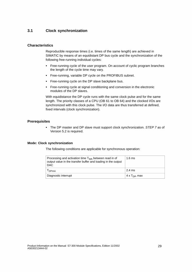
Mode: Clock synchronization
The following conditions are applicable for synchronous operation:
Processing and activation time TWA between read in ofoutput value in the transfer buffer and loading in the outputDAC
1.6 ms
TDPmin 2.4 ms
Diagnostic interrupt 4 x TDP, max
30 Product Information on the Manual S7-300 Module Specifications, Edition 11/2002A5E00213444-02
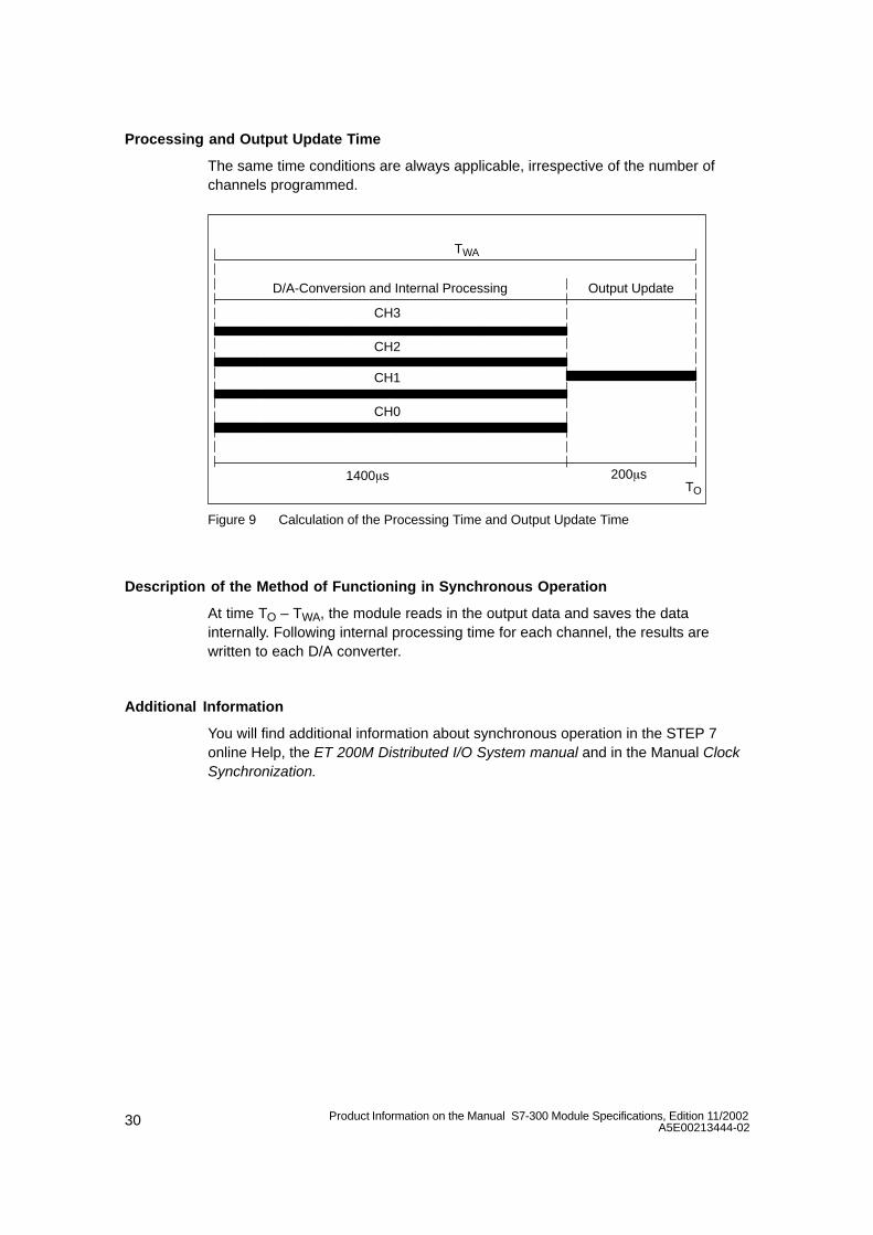
Processing and Output Update Time
The same time conditions are always applicable, irrespective of the number ofchannels programmed.
CH3
CH2
CH1
CH0
200s
D/A-Conversion and Internal Processing Output Update
TWA
TO1400s
Figure 9 Calculation of the Processing Time and Output Update Time
Description of the Method of Functioning in Synchronous Operation
At time TO – TWA, the module reads in the output data and saves the datainternally. Following internal processing time for each channel, the results arewritten to each D/A converter.
Additional Information
You will find additional information about synchronous operation in the STEP 7online Help, the ET 200M Distributed I/O System manual and in the Manual ClockSynchronization.
31Product Information on the Manual S7-300 Module Specifications, Edition 11/2002A5E00213444-02
3.2 Commissioning the SM 332; AO 4 16 bits
Parameter
You will find a description of the general procedure for assigning parameters toanalog modules in Section 4.7 of the reference manual.
You will find an overview of the programmable parameters and their default valuesin Table 4-42, on page 4-47 of the reference manual.
Assigning parameters to channels
You can configure each output channel of the SM 332; AO 4 16 bits individually.You can thus assign separate parameters for each output channel.
When you set the parameters with SFCs in the user program, the parameters areassigned to channel groups. Every output channel of the SM 332; AO 4 16 bits isassigned to a channel group in this instance – in other words, for example outputchannel 0 = channel group0.
Note
If you modify output ranges when the analog output module SM 332; AO 4 16bits is in operation, incorrect intermediate values may arise across the output.
Diagnostics
You will find the diagnostic messages that are grouped under the ”group diagnosis”parameter in Table 4-47, on page 4-79 of the reference manual.
32 Product Information on the Manual S7-300 Module Specifications, Edition 11/2002A5E00213444-02
3.3 Output Ranges of the Analog Output Module SM 332; AO 416 bits
Connecting the analog outputs
You can connect the outputs as voltage or current outputs, or disable them. Youperform connection of the outputs with the ”output type” parameter in STEP 7.
Unused channels
So that unused output channels of the SM 332; AO 4 16 bits remainde-energized, you must set the ”output type” parameter to ”disabled” and leave theterminal open.
Output ranges
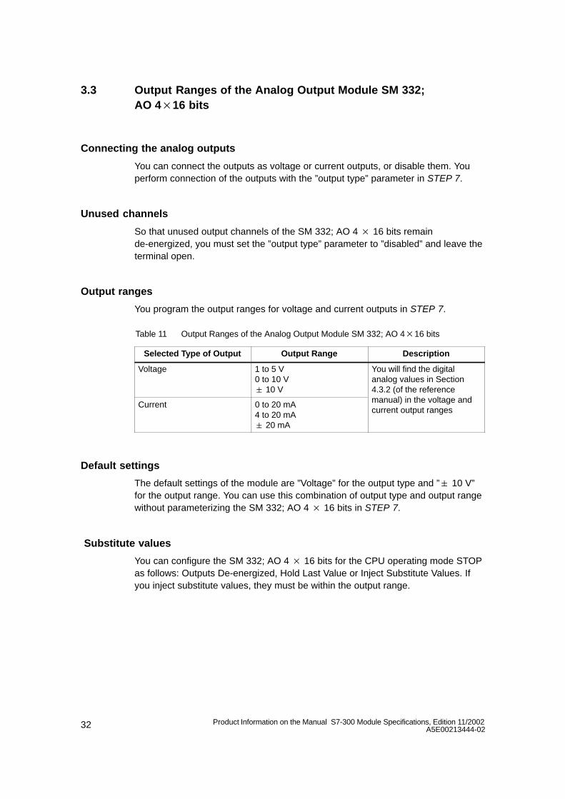
You program the output ranges for voltage and current outputs in STEP 7.
Table 11 Output Ranges of the Analog Output Module SM 332; AO 416 bits
Selected Type of Output Output Range Description
Voltage 1 to 5 V0 to 10 V 10 V
You will find the digitalanalog values in Section4.3.2 (of the reference
Current 0 to 20 mA4 to 20 mA 20 mA
manual) in the voltage andcurrent output ranges
Default settings
The default settings of the module are ”Voltage” for the output type and ” 10 V”for the output range. You can use this combination of output type and output rangewithout parameterizing the SM 332; AO 4 16 bits in STEP 7.
Substitute values
You can configure the SM 332; AO 4 16 bits for the CPU operating mode STOPas follows: Outputs De-energized, Hold Last Value or Inject Substitute Values. Ifyou inject substitute values, they must be within the output range.