Embed Size (px)
Citation preview
1
Università degli Studi di Torino
Scuola di Dottorato in Scienza e Alta Tecnologia
Tesi di Dottorato di Ricerca in Scienza e Alta Teconologia
Indirizzo: Informatica
Designing the Trustiness:
Driving and Driver Models for the Design of a
Cognitive Framework Supporting Adaptive
Safety-Critical Applications
Caterina Calefato
Tutor: Prof. Luca Console
XXII Ciclo, Novembre 2010
2
Università degli Studi di Torino
Scuola di Dottorato in Scienza e Alta Tecnologia
Designing the trustiness:
Driving and driver models for the design of a
cognitive framework supporting adaptive
safety-critical applications
Caterina Calefato
3
List of Contents
Chapter 1 Introduction ........................................................................................ 11
1.1 The driving task ..................................................................................................... 11
1.2 Beyond the State of Art ........................................................................................ 17
1.3 Objective of this thesis .......................................................................................... 22
Chapter 2 Adas as Recommender Systems for Complex Human-
Machine Interactions ........................................................................................... 24
2.1 The problem addressed: foreseeing the next accident ........................................ 24
2.2 Risk mitigation strategies: recommending the accident avoiding actions ........... 27
2.3 Matching the user behavior model with adaptive automation strategies: toward an adaptive driver assistance system .............................................................................. 31
2.3.1 The State of Art of Adaptive Automation: a critical literature review ............... 32
2.3.1.1 The problem of authority: from the delegation metaphor to the horse-
rider paradigm. ........................................................................................................ 38
2.3.1.2 Design issues .......................................................................................... 42
2.3.1.3 Adaptive Automation application in the design of preventive safety systems 43
Chapter 3 Reasons, aims and methods to study driver distraction ..... 45
3.1 Driver distraction problem ................................................................................... 45
3.2 The background of driving distractions: foundations and definitions ................. 47
3.2.1 Sources of distraction ......................................................................................... 50
3.2.2 Distraction as a contributing cause of crashes ................................................... 53
3.2.3 Effects of distraction on driving performance.................................................... 54
3.2.3.1 Mobile Phones ........................................................................................ 55
3.2.3.2 Navigation systems ................................................................................ 55
3.2.3.3 Email ....................................................................................................... 56
3.2.3.4 Entertainment Systems .......................................................................... 56
3.2.3.5 Everyday Activities ................................................................................. 56
3.2.3.6 External Distractions .............................................................................. 57
3.2.3.7 Engaging distracting activities: impact on driving performance............ 57
3.2.3.8 Measurement of driving distraction ...................................................... 59
3.2.3.9 On-road and Test Track Studies ............................................................. 59
3.2.3.10 Driving Simulators .................................................................................. 60
3.2.3.11 Dual-task Studies .................................................................................... 61
3.2.3.12 Eye Glance Studies ................................................................................. 61
4
3.2.3.13 The Visual Occlusion Technique ............................................................. 62
3.2.3.14 The 15-second Rule ................................................................................ 63
3.2.4 Factors moderating the impact of distraction on driving performances and safety 63
3.2.4.1 Education ................................................................................................ 64
3.2.4.2 Self-regulation ........................................................................................ 64
3.2.4.3 Training ................................................................................................... 65
3.2.4.4 Vehicle Design ........................................................................................ 65
3.2.4.5 Road Design ............................................................................................ 66
3.2.4.6 Research ................................................................................................. 66
3.2.5 Design and standardization ................................................................................ 67
3.2.5.1 European approaches to principle, codes, guidelines for In-Vehicle HMI
67
3.2.5.2 North-American approaches to principle, codes, guidelines for In-
Vehicle HMI ............................................................................................................. 69
3.2.5.3 Japanese approaches to principle, codes, guidelines for In-Vehicle HMI 71
3.2.6 Prevention and mitigation strategies ................................................................. 72
3.2.6.1 Driving-related tasks .............................................................................. 73
3.2.6.2 Non-Driving-related tasks ...................................................................... 74
3.3 Machine Learning and User Modeling: the lesson learned .................................. 77
3.3.1 Brief overview of machine learning techniques in driver’s modeling ................ 80
3.3.2 Machine learning in distraction modeling .......................................................... 82
Chapter 4 Integration of a driver behavior model into a cognitive
architecture ............................................................................................................. 89
4.1 Cognitive architecture: research issues and challenges in HCI. ........................... 89
4.1.1 Example of Past Cognitive Architecture ............................................................. 93
4.1.1.1 The Model Human Processor (MHP)...................................................... 93
4.1.2 GOMS (goals, operators, methods, and selection rules) ................................... 96
4.1.3 Cognitive Complexity Theory (CCT) .................................................................... 97
4.1.3.1 CAPS ....................................................................................................... 98
5
4.1.4 Example of Current Cognitive Architecture ....................................................... 98
4.1.4.1 LICAI/CoLiDeS ......................................................................................... 98
4.1.4.2 Soar ....................................................................................................... 100
4.1.4.3 EPIC ....................................................................................................... 101
4.1.4.4 ACT-R .................................................................................................... 103
4.1.4.5 Icarus .................................................................................................... 104
4.2 Driver behavior model and cognitive architecture: a feasible integration ........ 105
4.3 Cognitive framework in the automotive domain: the Joint Driver-Vehicle-Environment Model ....................................................................................................... 108
Chapter 5 The Implementation of adaptation, driver status and
maneuvers recognition strategies: empirical results. ............................ 116
5.1 Improving driving performance by adaptation: the Force Feedback steering wheel 116
5.1.1 Investigating the effects of the Force Feedback steering wheel ..................... 118
5.1.1.1 The Context Dependant Steering Wheel: testing the adaptation strategy 120
5.2 Assessing driver’s status: how to improve adaptation by driver’s model trigger. 126
5.2.1 Inputs and target output indicators for driver model training and testing:
Matlab™ coding .............................................................................................................. 130
5.2.2 Adaptive Neuro Fuzzy inference system and Neural Network models of Task Demand and Distraction parameters: Matlab™ coding ................................................. 136
5.2.2.1 Adaptive Neuro Fuzzy inference model ............................................... 137
5.2.2.2 Neural Network model ......................................................................... 138
5.3 Understanding driver’s maneuvers by the use of Add. On Functionalities ........ 142
5.3.1 Driving behaviour ............................................................................................. 142
5.3.2 Driver Behaviour ............................................................................................... 144
5.3.3 Conditions for the implementation of Add-On Functionalities ....................... 145
5.3.4 Add-On Functionalities Inputs .......................................................................... 146
5.3.5 Improving adaptive automation strategies by AoF: empirical results ............. 147
5.3.5.1 Driver Stress (DS) .................................................................................. 147
5.3.5.2 Traffic congestion (TC). ........................................................................ 148
5.3.5.3 Road Conditions (RC). ........................................................................... 148
5.3.5.4 AOF test and tuning: Driver Stress ....................................................... 151
6
Chapter 6 A Framework for Cognitive vehicles supporting human-
robot interactions: the horse-rider architecture of ADAS+ .................. 154
6.1 A cognitive driving assistance system ................................................................. 154
6.2 From ADAS prediction system to ADAS+ symbiotic system ................................ 157
6.3 ADAS+ proposed architecture following the H-metaphor ................................. 159
6.3.1 Perceptual Subsystem for the Environment Assessment ................................ 161
6.3.2 Cognitive Subsystem for the Maneuver Implementation . .............................. 162
Chapter 7 Conclusions ....................................................................................... 164
7.1 Final remarks ....................................................................................................... 164
7.2 Future works ....................................................................................................... 166
Chapter 8 References ......................................................................................... 167
7
List of Figures
Figure 1 Scope of this tesi within the research objectives. ................................................. 23
Figure 2 Automation Design Consideration [69]. ................................................................ 33
Figure 3 Stages of Human Information Processing ............................................................. 38
Figure 4 The manual DWE design process [252] ................................................................. 84
Figure 5 The learning-based DWE design process [252] ..................................................... 85
Figure 6 The Model Human Processor (MHP) diagram [45] ............................................... 94
Figure 7 Driver-Vehicle-Environment (DVE) conceptual scheme ...................................... 109
Figure 8 DVE frame work architecture .............................................................................. 110
Figure 9 CDSW implemented on the driving simulator [164] ........................................... 121
Figure 10 Interpolation between consecutive Force-Feedback (FF) [164]. ...................... 122
Figure 11 The Matlab™ Simulink model concerning the High Frequency component of
Steering angle (HFS) .......................................................................................................... 124
Figure 12 Drivers' group performances measured with Standard Deviation of steering
angle [164]. ........................................................................................................................ 125
Figure 13 SURT task inducing distraction on the driving simulator .................................. 129
Figure 14 The ANFIS model created for the Distraction assessment ................................ 138
Figure 15 On the left side of this figure there is the scheme of the neural network, where
blue elements represent the hidden (left) and visible (right) neurons. On the right side, a
plot of the training, checking and testing phase of the developed Distraction neural
network model. In the bottom figure, the values (curves) of RMSE obtained in the
training, validation and test phase of the model. ............................................................. 140
Figure 16 Prediction (circles) done by the model of drivers’ distraction before the training
ad validation phases vs target distraction values ............................................................. 140
Figure 17 Prediction (circles) done by the model of drivers’ distraction after the training
and validation phases with the Feed-Forward Neural Network vs target distraction values
........................................................................................................................................... 141
Figure 18 - Driving scenario (track). .................................................................................. 152
Figure 19 - DS compared with steering angle. .................................................................. 153
Figure 20 The rider-horse metaphor ................................................................................. 158 Figure 21 ADAS+ system architecture ................................................................................ 160
8
List of Tables
Table 1 – Review of the ADAS technologies [68] ............................................................... 17
Table 2 Common elements of distraction definitions and examples of each element [207]
............................................................................................................................................. 49
Table 3 Time spent by drivers in engaging distracting activities [228] ............................... 51
Table 4 Technology-based distraction and non technology-based distraction sources [252]
............................................................................................................................................. 52
Table 5 Contribution of each distraction sources in crashes due to distraction [206] ....... 53
Table 6 Impact of distracting activities on driving performance [252] ............................... 57
Table 7 Comparison of key HMI issues for different IVIS and ADAS functionalities [207].. 68
Table 8 Taxonomy of distraction mitigation strategies [67]. .............................................. 72
Table 9 Cycle and decay time [45] ....................................................................................... 94
Table 10 p-values of the Standard Deviation of steering angle, with reference to the
scenario and drivers' group [165]. ..................................................................................... 124
Table 11 Driving conditions (1, 2.., 9), inputs (visibility, traffic density, SURT) and values:
(L)ow, (M)edium, (H)igh, (N)o task [235]. ......................................................................... 129
Table 12 Available Chassis Sensors and related AoFs. ...................................................... 146
Table 13 -. AOFs’ input ...................................................................................................... 149
Table 14 - Matlab/Simulink model for DS computation ................................................... 150
9
Abstract
Statics show that every year, about 35 000 people die and 1.3 million people are injured
in traffic accidents in Europe. In Italy about 4 000 people die and 230 000 people are
injured in traffic accidents.
Driving a motor vehicle is a really complex and potentially dangerous task. Despite this
complexity, it is common for drivers to engage a secondary task as inputing the navigation
system, changing the radio station, talking on the mobile phone. All these activities divert
the attention away from the road. In addition to the safety issues associated with the
driving task, the proliferation of complex in-vehicle functions itself poses a further
challenge for the design of the driver-vehicle interface. Interaction with these devices is
one of the many activities that constitutes driving and so it can represent an additional
source of driving-related distraction.
Among these devices, Advanced Driver Assistance Systems (ADAS) are systems that
support the driver in the driving process, detecting a dangerous situation and giving a
warning. Eventually they can intervene in the driving task, performing a repairing
manoeuvre. Preventive safety systems are able to mitigate human errors.
An interesting and challenging approach is to design ADAS as a cognitive system, adding a
learning capability able to make the ADAS more effective and smarter. The development
of such an ADAS, named ADAS+, brings together three building blocks: a driver model, a
driving model and an adaptation strategy derived from the interactions between the
driver and the system.
The proposal of such an architecture is allowed by the empirical validation of the driver
and driving model and of the effectiveness of adaptation strategies in improving driving
performance. The driver model will particularly focus on the assessment of driver’s
distraction, that is one of the most challenging driver behaviour factor to be modelled.

10
The aim of this thesis is to empirically verify the effectiveness of each of the essential
aspect of an ADAS+ in improving the driving performance. This empirical validation of the
driver and driving model, and of the adaptation strategies, allow us to place all these
three elements into a new cognitive framework.
11
Chapter 1
Introduction
1.1 The driving task
Driving a motor vehicle is, for many people, the most complex and potentially dangerous
task they will perform during their lifetime. Despite this complexity, it is common for
drivers to engage, willingly or unwittingly, in activities that divert their attention away
from activities critical for safe driving. It is common sense that distraction is part of
everyday driving and that distraction degrades driving performance and safety [207].
Every year, about 35 000 people die and 1.3 million people are injured in traffic accidents
in Europe. In Italy about 4 000 people die and 230 000 people are injured in traffic
accidents [69] [47].
These figures imply that 78 people out of every million of European citizens die in a traffic
accident each year and that around one out of 80 European citizens die 40 years earlier of
their expected lifetime [48]. It is known that the most part of road accidents are caused
by human error and there is a converging evidence that driver distraction is a significant
road safety worldwide.
Findings from the analysis of police-reported crashes suggest that driver distraction is a
contributing factor in up of 23% of crashes, but it may be underestimated, due to the
different measurement methods [207]. In fact these studies these studies report high
levels of “unknown” information where the driver inattention status was recorded as
1.1 The driving task
12
unknown or missing in up of the 40% of the cases. It has been proposed that driver
distraction/inattention might be involved in 25-30% of crashes [228].
The 100-car study provides a reliable indication of what the level of underestimation
might be for secondary task activities. The 100-car naturalistic driving study is a different
type of crash study in that it does not rely on secondary data such as police reports or
crash investigations but collects data directly by instrumented vehicles (for details
see[173]). Based on population-attributable risk calculation, which takes into account
exposure information, secondary task distraction is estimated to be involved in 23% of
crashes and near crashes. However, if distraction is considered to include other forms of
inattention, such as driving-related inattention or non-specific eye glances, then the level
of involvement in crashes will be substantially higher [207].
Considering that driving is a complex, multitask activity, making it likely that the demands
of one element of driving will interfere with another element, distraction becomes more
important as Advanced Driver Assistance Systems (ADAS) become more prevalent and
powerful.
In addition to the safety issues associated with the driving task, the proliferation of
complex in-vehicle functions itself poses a further challenge for the design of the driver-
vehicle interface. Interaction with these devices is one of the many activities that
constitutes driving and so it can represent an additional source of driving-related
distraction [207]. For example poorly designed collision warning systems may be even
more likely to distract drivers; navigation represents a driving-related task with
substantial potential to distract [173] [66]. Considering driving tasks as potential
distraction is important because ADAS will become an increasingly powerful force in
directing the attention of the drivers to what ADAS estimates to be critical elements of
the roadway environment.
The analysis of ADAS working conditions, architectures and performances brought us to
find a new design framework for this kind of system, paying attention to the integration
of driver and driving models into a cognitive architecture.
Advanced Driver Assistance Systems, or ADAS, are systems that help the driver in its
driving process: they detect a dangerous situation and gives a warning and eventually
they can intervene in the driving task, performing a repairing manoeuvre.
Chapter 1 Introduction
13
This can be considered as an issue of collaborative control between the human and the
system during the supervisory control (human perception and cognition) without
requiring time critical or situation critical response from the human — it can still function
if human is not available. The key aspects relevant for the collaborative control are: self
awareness (capable of detecting limitations), self reliance (capability to guarantee its own
safety), dialogue (effective two way communication between human and robot, that can
be speech but also haptic, graphics, etc to provide humans and robot with models of each
others which is a great challenge), adaptive (to behaviour of different operators) [73]
In order to design human-centred automated systems it is necessary to take into account
the way humans process information, focusing carefully on the participation and the
autonomy that humans and machines may have in each task to be performed. There are
researches that face the crucial issue of the authority that each part should have in
controlling the system [42][225]. Historically humans played the role of system monitors,
i.e. the machine decides about the actions and the humans evaluate these decisions and
based on them they regain or not the control on the actions[224]. In this effort a crucial
role is played by the human skills and abilities and by the systems natural limits[187]
If the system only gives a warning, hence coping with the situation analysis and
evaluation, is usually defined analytical [7]: it warns the driver suggesting accident-
avoiding maneuvers.
If beside the analysis and evaluation functions, the ADAS adds a concrete behavior, acting
during the driving task in order to avoid an accident or to repair a maneuver, it is
behavioral: it acts in place of the driver, partially taking over a certain driving task [7]
[101].
In the case of analytical ADAS we can consider there are two actors playing a role:
• The driver
• The warning system
In the case of behavioral ADAS we can consider there are three actors playing a role:
• The driver
• The horse or co-pilot (the artificial system able to drive in place of the driver (see
[72] and paragraph 2.3.1.1)
1.1 The driving task
14
• The warning system
In both cases, analytical and behavioral ADAS, there is a warning system that detects the
dangerous situation and then provides the driver a safety warnings suggesting accident-
avoiding maneuvers, or or in case of particularly sophisticated ADAS; directly implentig
them. The analysis of the risky situation includes the assessment of the driver, vehicle and
environment (DVE) conditions. The evaluation of the driver is possible by means of a
driver model: in fact, ADAS applications represent a challenging test bed for the
implementation and validation of user behavioral modeling systems, that may be realized
by means of Machine Learning techniques, as the domain literature suggests.
In order to address and deal with these critical safety challenges, the design of ADAS
meant as recommending systems able to support and cooperate with users in their
driving task, have been broadly investigated in these years. In fact collaborative driving is
an important sub-component of the so-called Intelligent Transportation Systems (ITS).
The purpose of these systems is to foresee and detect possible driver’s errors and
mistakes, due to a misbehavior such as distraction, or resulting from too high workload,
missing perception, wrong action/execution or poor operator skills.
The ADAS design is aimed at enhancing the driver’s perception of hazards and critical
situations (in some cases, by partly automating the driving task as well). These
applications include anti-collision systems, lane change support and blind spot detection,
pedestrian detection, night-vision enhancement, driver impairment monitoring and
adaptive cruise control. Of course the potential of such systems in reducing accidents
depends on the effectiveness of the their interaction with the driver. For example, in the
case of an anti-collision systems it is safety-critical that the collision warning is able to
generate the appropriate feedback (e.g. an avoidance maneuver).
Since, as stated before, ADAS can be actually considered recommending systems, the use
of an appropriate driver’s model improve their effectiveness and consequently, human
safety. Hence it is crucial that automated or partially automated systems should take into
consideration a user model, that tries to foresee the user future behavior.
The need of an effective user model is a requirement for any recommending system, as
faced and confirmed by the domain literature on user modeling and automatic
recommending systems. This requirements is crucial for any recommending system that
has to cope with time-criticality, that directly affects safety. The ADAS applications are
Chapter 1 Introduction
15
examples of such systems and they represents a challenging test bed for the
implementation and validation of user behavioral modeling systems.
Basically, the human behavior is characterized by the interactions between driver-vehicle
and driver environment. The first interaction is related to how the driver interacts with
the vehicle and all systems and sub-systems on-board. The second interaction is related
to how drivers perceive and process the data coming out from the surrounding scenario.
Hence, the driver model should be adaptive to different drivers’ style and preferences as
well as to the external environment (including learning both from the driving experience
and from the surrounding conditions), but overall it should allow to assess and foresee
distraction. Preventing distraction permit to prevent driving errors and accident risk, as a
consequence, a risk based design approach is crucial for the design of vehicles and
transport systems in order to guarantee safety and efficiency of human mobility.
Pat Langley [138] considers information filtering and recommendation systems as typical
examples of adaptive interfaces, defining adaptive interfaces as “software artifacts that
improve their ability to interact with users by constructing user models based on partial
experience with each of them”. The response to the ITS (Intelligent Transportation
Systems) challenge to create adaptive applications for road vehicles come from various
disciplines including machine learning and data mining, intelligent agents and multi-agent
systems, intelligent tutoring, information retrieval, etc. User modeling (UM) aims to aims
at improving system effectiveness and reliability by adapting the behavior of the system
to the needs of the individual. The importance of adding this capability to information
systems is proven by the variety of areas in which user modeling has already been
applied: information retrieval, filtering and extraction systems, adaptive user interfaces,
educational software, safety-critical systems .
Starting from these considerations in this PhD thesis we will go further the ADAS
literature, associating the ADAS work to the work of a general recommender system.
Both, the ADAS and the recommender system, to effectively provide recommendations
(or warnings) should be able to detect the context-environment conditions and to infer
the user status, thanks to a user model or profile. The user behavior model improves the
system prediction capability, reducing as a consequence the error margin in terms of
prediction and then action.
1.1 The driving task
16
Reducing errors means, in other words, reducing the risk of accidents that is the main
purpose of safety critical systems, such as ADAS.
Therefore, a method for detecting and classifying driver’s intention (i.e. the driving
maneuver) and distraction is essential to facilitate operating mode transition between
users and driver assistance systems. This kind of transition, also known in literature as
Dynamic Function Allocation [115], is the guiding principle of the Adaptive Automation.
In this thesis, a driver and driving assessment method is proposed, mainly based on
Machine Learning techniques. The empirical verification of the effectiveness of the
driver and driving model, togheter with the verification of the usefulness of adaptation
strategies in improving driving performance, allow us to place all these three elements
(driver model, driving model, adaptation strategy) into the cognitive framework for the
design of a behavioural ADAS, that we will label ADAS+
.
17
1.2 Beyond the State of Art
Driving is considered as a complex cognitive task that can be summarized by four main
sub-processes: perception, analysis, decision and action. To be performed, each phase
presumes the achievement of the previous one.
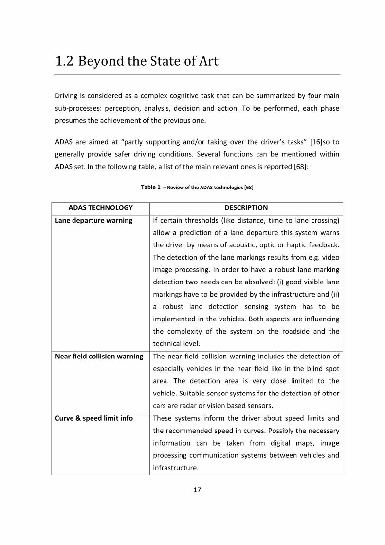
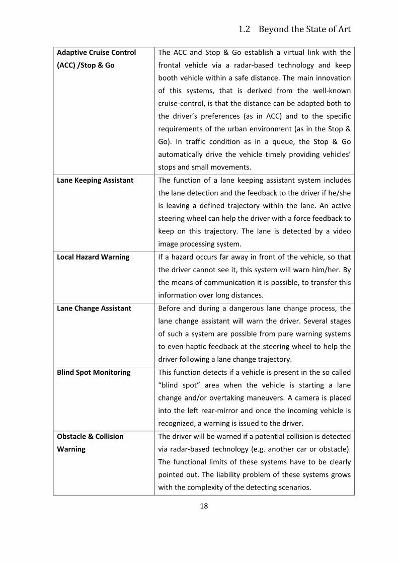
ADAS are aimed at “partly supporting and/or taking over the driver’s tasks” [16]so to
generally provide safer driving conditions. Several functions can be mentioned within
ADAS set. In the following table, a list of the main relevant ones is reported [68]:
Table 1 – Review of the ADAS technologies [68]
ADAS TECHNOLOGY DESCRIPTION
Lane departure warning If certain thresholds (like distance, time to lane crossing)
allow a prediction of a lane departure this system warns
the driver by means of acoustic, optic or haptic feedback.
The detection of the lane markings results from e.g. video
image processing. In order to have a robust lane marking
detection two needs can be absolved: (i) good visible lane
markings have to be provided by the infrastructure and (ii)
a robust lane detection sensing system has to be
implemented in the vehicles. Both aspects are influencing
the complexity of the system on the roadside and the
technical level.
Near field collision warning The near field collision warning includes the detection of
especially vehicles in the near field like in the blind spot
area. The detection area is very close limited to the
vehicle. Suitable sensor systems for the detection of other
cars are radar or vision based sensors.
Curve & speed limit info These systems inform the driver about speed limits and
the recommended speed in curves. Possibly the necessary
information can be taken from digital maps, image
processing communication systems between vehicles and
infrastructure.
1.2 Beyond the State of Art
18
Adaptive Cruise Control
(ACC) /Stop & Go
The ACC and Stop & Go establish a virtual link with the
frontal vehicle via a radar-based technology and keep
booth vehicle within a safe distance. The main innovation
of this systems, that is derived from the well-known
cruise-control, is that the distance can be adapted both to
the driver’s preferences (as in ACC) and to the specific
requirements of the urban environment (as in the Stop &
Go). In traffic condition as in a queue, the Stop & Go
automatically drive the vehicle timely providing vehicles’
stops and small movements.
Lane Keeping Assistant The function of a lane keeping assistant system includes
the lane detection and the feedback to the driver if he/she
is leaving a defined trajectory within the lane. An active
steering wheel can help the driver with a force feedback to
keep on this trajectory. The lane is detected by a video
image processing system.
Local Hazard Warning If a hazard occurs far away in front of the vehicle, so that
the driver cannot see it, this system will warn him/her. By
the means of communication it is possible, to transfer this
information over long distances.
Lane Change Assistant Before and during a dangerous lane change process, the
lane change assistant will warn the driver. Several stages
of such a system are possible from pure warning systems
to even haptic feedback at the steering wheel to help the
driver following a lane change trajectory.
Blind Spot Monitoring
This function detects if a vehicle is present in the so called
“blind spot” area when the vehicle is starting a lane
change and/or overtaking maneuvers. A camera is placed
into the left rear-mirror and once the incoming vehicle is
recognized, a warning is issued to the driver.
Obstacle & Collision
Warning
The driver will be warned if a potential collision is detected
via radar-based technology (e.g. another car or obstacle).
The functional limits of these systems have to be clearly
pointed out. The liability problem of these systems grows
with the complexity of the detecting scenarios.
Chapter 1 Introduction
19
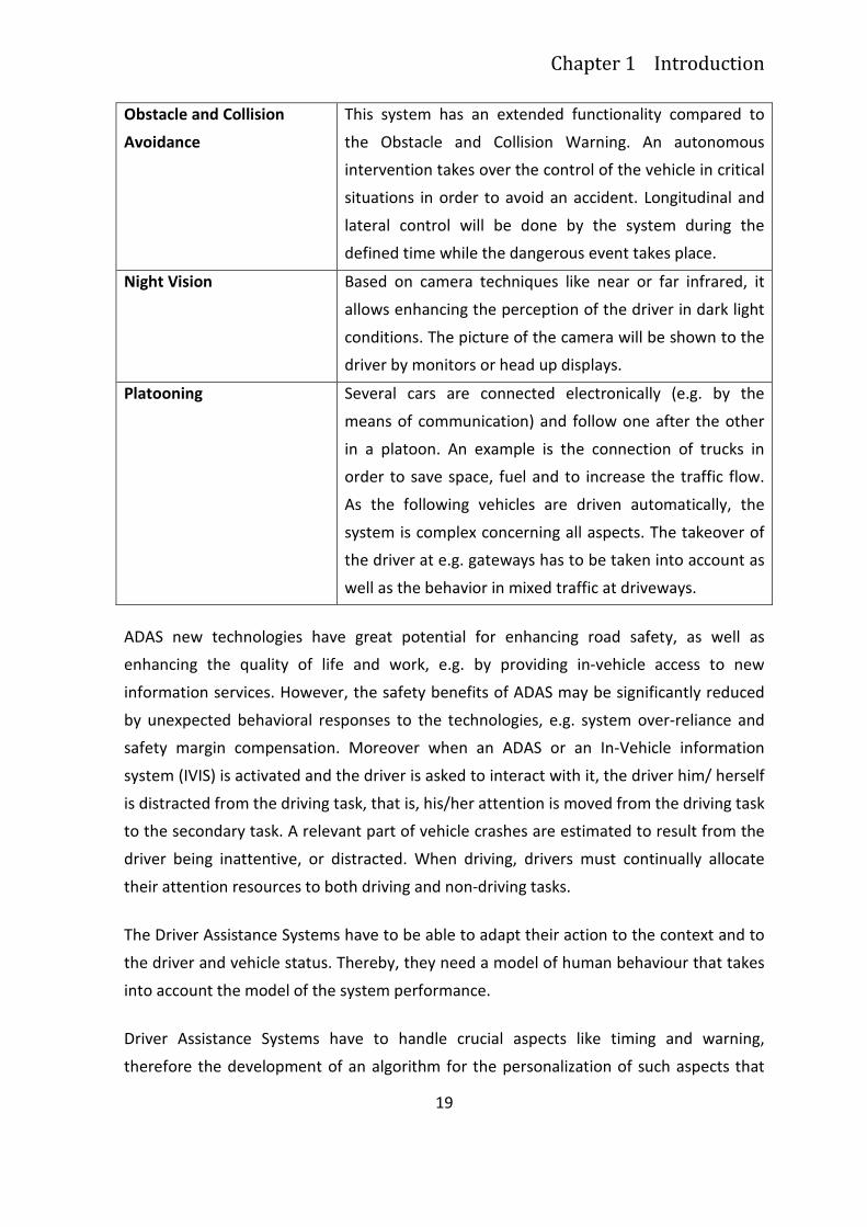
Obstacle and Collision
Avoidance
This system has an extended functionality compared to
the Obstacle and Collision Warning. An autonomous
intervention takes over the control of the vehicle in critical
situations in order to avoid an accident. Longitudinal and
lateral control will be done by the system during the
defined time while the dangerous event takes place.
Night Vision
Based on camera techniques like near or far infrared, it
allows enhancing the perception of the driver in dark light
conditions. The picture of the camera will be shown to the
driver by monitors or head up displays.
Platooning
Several cars are connected electronically (e.g. by the
means of communication) and follow one after the other
in a platoon. An example is the connection of trucks in
order to save space, fuel and to increase the traffic flow.
As the following vehicles are driven automatically, the
system is complex concerning all aspects. The takeover of
the driver at e.g. gateways has to be taken into account as
well as the behavior in mixed traffic at driveways.
ADAS new technologies have great potential for enhancing road safety, as well as
enhancing the quality of life and work, e.g. by providing in-vehicle access to new
information services. However, the safety benefits of ADAS may be significantly reduced
by unexpected behavioral responses to the technologies, e.g. system over-reliance and
safety margin compensation. Moreover when an ADAS or an In-Vehicle information
system (IVIS) is activated and the driver is asked to interact with it, the driver him/ herself
is distracted from the driving task, that is, his/her attention is moved from the driving task
to the secondary task. A relevant part of vehicle crashes are estimated to result from the
driver being inattentive, or distracted. When driving, drivers must continually allocate
their attention resources to both driving and non-driving tasks.
The Driver Assistance Systems have to be able to adapt their action to the context and to
the driver and vehicle status. Thereby, they need a model of human behaviour that takes
into account the model of the system performance.
Driver Assistance Systems have to handle crucial aspects like timing and warning,
therefore the development of an algorithm for the personalization of such aspects that
1.2 Beyond the State of Art
20
takes into account driver distraction or workload is needed. Distraction is on one of the
most challenging driver behaviour factor to be modelled.
Regarding the drivers’ intention prediction, several models have been proposed aiming at
reproducing in a virtual environment how the drivers could behave according to specific
Driver, Vehicle or Environment conditions. In the domain literature there are different
approaches like:
1. the IPS (Information Processing System), which has been applied in almost all
technological fields to describe human interaction with control systems, at
different levels of automation [174] [177]
2. the PIPE (Perception, Interpretation, Planning and finally Execution) based on a
very simple approach that assumes that behaviour derives from a cyclical
sequence of the four cognitive functions quoted in brackets [40].
The development of a model of the human machine system is driven by the model of the
Driver, which is the most complex element of the system.
Concerning the design of algorithms used to represent the Driver behaviour, previous and
ongoing studies propose different approaches based on the real-time monitoring of the
drivers’ performance [149] (e.g. variation of the position on the road, speed, steering
wheel movements) or the drivers’ physiological status performing primary and secondary
tasks (e.g. eye gaze, eye movements, heart frequency variation, galvanic skin response,
etc.) [111]. Basing on this information, these approaches allow to predict specific drivers’
profiles (e.g. stressed, aggressive, tired, distracted, high workload etc.) and are developed
following machine learning approaches. Thanks to machine learning, information on
drivers’ profile can be automatically extracted from data, by computational and statistical
methods applied to observable information (e.g. drivers’ performance data) [234] [235]
[236].
On one hand the assessment of the driver’s status and consequentially the prediction of
his/her next behaviour is easier and most successful using driver’s physiological data, as
for example the eye gaze and the eye movements measured by means of eye tracker. On
the other hand eye-tracking is an intrusive measurement system of distraction, it
represents a further equipment and a further cost that stand in the way of a next future
mass-marketing. What is really interesting and challenging is to obtain a driver index
Chapter 1 Introduction
21
analysing driving performance data, realising what it may be considered an ADD-On
Functionalities.
Add-On Functionalities can be divided in two main categories [1]:
• Driving Behaviour: i.e. Add-On Functionalities related to driving performance.
Main objective of these AOF is to estimate driving conditions concerning road,
dynamics and current manoeuvre.
• Driver Behaviour: these AOF deal with driver current state, mainly intended as
mental effort (or workload) related to the driving task.
These two macro-areas can be considered as complementary. As a matter of fact, they
cover two different aspects of driving task: concerning driving behavior, AOFs try to
estimate possible safety critical driving conditions by monitoring data describing vehicle
state, hence from mechanical domain. About driver behavior, AOFs achieve information
from driver’s actions hence from a human domain.
22
1.3 Objective of this thesis
Driver modeling is a scientific area involving several disciplines, such as psychology,
physics, computer science, etc. The importance of adding the learning capability to
information systems, in order to make them more effective and smarter, is confirmed by
the variety of areas in which user’s modeling has already been applied: information
retrieval, filtering and extraction systems, adaptive user interfaces, educational software,
etc.
In relation to the problem formulated above, the aim of this thesis is to define a cognitive
architecture for the development of a behavioural ADAS, named ADAS+, that brings
together the driver model, the horse or co-pilot model, and an adaptation strategy
derived from the interactions between the driver and the horse.
The proposal of such an architecture is allowed by the empirical validation of the driver
and driving model and of the effectiveness of adaptation strategies in improving driving
performance. The driver model will particularly focus on the assessment of driver’s
distraction, since, as stated before, it is one of the most challenging driver behaviour
factor to be modelled. The literature proposes many methods to evaluate and classify
driver’s distraction [154] [234] [235] [236] [251] [249]. In particular, Machine Learning
(ML) approach seems to be really appropriated for this type of classification problem.
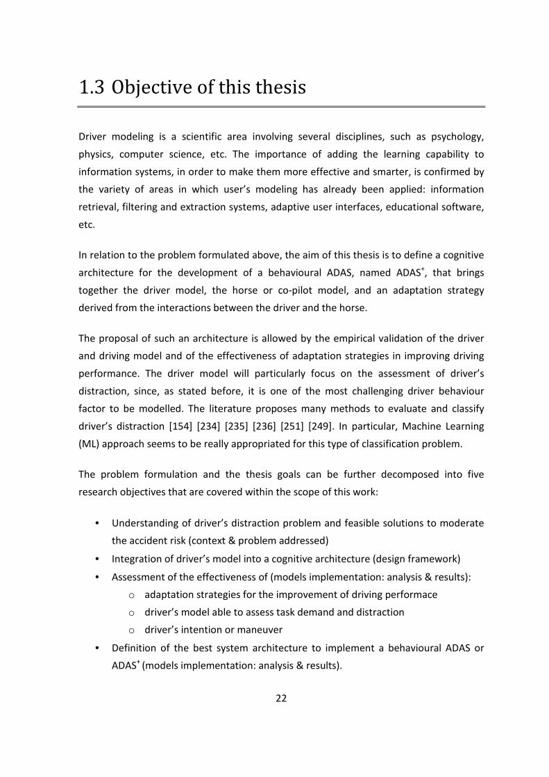
The problem formulation and the thesis goals can be further decomposed into five
research objectives that are covered within the scope of this work:
• Understanding of driver’s distraction problem and feasible solutions to moderate
the accident risk (context & problem addressed)
• Integration of driver’s model into a cognitive architecture (design framework)
• Assessment of the effectiveness of (models implementation: analysis & results):
o adaptation strategies for the improvement of driving performace
o driver’s model able to assess task demand and distraction
o driver’s intention or maneuver
• Definition of the best system architecture to implement a behavioural ADAS or
ADAS+ (models implementation: analysis & results).
Chapter 1 Introduction
23
Figure 1 Scope of this tesi within the research objectives.
24
Chapter 2
Adas as Recommender Systems for
Complex Human-Machine
Interactions
2.1 The problem addressed: foreseeing the
next accident
Accidents and the threat of accidents are the primary motivators for work on safety.
Over the past 30 years, the literature shows a consistent trend in trying to understand
accidents in aviation, nuclear power generation, telecommunications, unmanned and
manned spaceflight, railroad transport, shipping, healthcare and many other fields [49].
Regardless of the domain of investigation, there are some crucial questions to which the
research is trying to find an answer: How do accidents happen and what do they mean?
Are accidents foreseeable? If so, are they preventable? What role does technology play in
accidents? What role does human performance play? Are accidents evidence of systemic
problems or are they isolated failures? If accidents are systemic, how can the system be
fixed to prevent future accidents [61]?
Chapter 2 Adas as Recommender Systems for Complex Human-Machine
Interactions
25
Both accidents and post-accident investigation and analysis take place within a complex
system that includes many elements: people, goals, technology, incentives, rules,
knowledge, and expertise. The connection among them represent the main obstacle in
understanding and analyzing accidents, but what is of major concern, it makes it hard to
foresee future failures. The direct consequence is that whether it is difficult to imagine
how future accidents will occur, for sure it is difficult to plan work on safety.
Since accidents are surprising, it is hard to prevent them before they occur: the history of
complex systems is sadly scarred by such events: the Three Mile Island nuclear meltdown,
the Challenger explosion, and the attacks of 9/11 are some well-known examples [49]
[61].
What interestingly arose from the post-accident analysis is that the technical details of
these events were all more or less well understood before the events occurred. “What
was lacking was the ability to foresee that circumstances would conspire to create the
conditions needed to make these technical features active and lethal” [61].
That said, what it may be interesting to study is the detection of an accident pre-
conditions and which may be the conditions combination (circumstances) that may lead
toward an accident. For each combination (that we may label risk layouts) a mitigation
strategy will be applied in order to avoid a possible accident. It is common sense that
successful accident investigation requires knowledge of both technical and organizational
characteristics (including the task actors and roles) and understanding of the ways these
characteristics interact.
The specific accidents that it is possible to clearly foresee are consequently prevented. It
is the ones that is not possible to foresee that occur. An adaptive system should be able
to detect risk layouts and dynamically adapt its behavior in order to avoid accident, but
the failure factor in this scheme is change.
In a complex system formed by a context, a predictable system (including automatic
applications) and the human being, the unpredictable factor is the human being behavior
and its combination to a certain context. The unpredictable change due to the human
factor produces a complex set of organizational reverberations that are difficult to
anticipate or predict and may go far beyond the expectations of designers.
2.1 The problem addressed: foreseeing the next accident
26
Although information technology can defend against some types of accidents and
failures, the impact of automation on human-machine system performance is a mixture
of desirable and undesirable effects. For example in commercial aviation, cockpit flight
management systems have changed the nature of the pilot’s work, creating new tasks
and augmenting workload [194]. Although automation may reduce workload in one area,
for example within automotive (i.e. route navigation, frontal collision warning), it will also
generate new workload (i.e. navigating through multiple displays, switching between
primary and secondary tasks).
As stated in the introduction, systems like ADAS have great potential for enhancing road
safety, but on the other hand the safety benefits of ADAS may be significantly reduced by
unexpected behavioral responses to the technologies, e.g. system over-reliance, safety
margin compensation and distraction, leading toward an automation failure. The
automation failure is a side effect of an effort to produce ‘‘safety’’ [49].
Summing up accidents occur because multiple factors combine to create the necessary
conditions for them. Because the pattern of factors in the automotive domain is
constantly changing (new technologies and devices on board, new infrastructure, new
mobility concepts, new trends in pollution prevention), the accident characteristics of the
system are also changing. Even there is not feasible to exactly predict the next accident, it
is possible to anticipate some decisive characteristics of future accidents, as driver’s
distraction.
27
2.2 Risk mitigation strategies: recommending
the accident avoiding actions
Recommender systems have become a promising research area since the appearance of
the first papers on collaborative filtering in the mid 1990s [100][208] [220]. This area is
promising because it represents a problem-rich research area and because of the wide
opportunities of practical applications that help users to deal with information overload
and provide personalized recommendations, content, and services to them, in several
applications domain as infotainment, e-commerce, transport and healthcare.
As formally defined by [2], the recommendation problem can be formulated as follows
[100][208] [220]:
Let be C the set of all users and let be S the set of all possible items that can be
recommended, such as books, movies, restaurants, touristic information, actions to be
performed.
The space S of possible items can be very big, ranging in hundreds of thousands or even
millions of items in some applications, such as recommending books. Similarly, the user
space can also be very big—millions in some cases. Let u be an utility function that
measures the usefulness of item s to user c, i.e., �: � � � � �, where R is a totally
ordered set (e.g., nonnegative integers or real numbers within a certain range). Then, for
each user �, we want to choose such item �� � that maximizes the user’s utility.
More formally:
� �, ��� � arg max � �, ��. (1)
� �
In recommender systems, the utility of an item is usually represented by a rating, which
indicates how a particular user liked a particular item or how a particular item is
appropriate for a certain user, taking care of a set of context conditions. Generally
speaking , utility can be an arbitrary function, including a profit function. Depending on
the application, utility u can either be specified by the user, as is often done for the user-
2.2 Risk mitigation strategies: recommending the accident avoiding
actions
28
defined ratings, or is computed by the application, as can be the case for a profit-based
utility function [2][1].
To each element of the user space C can be associated a profile that includes the user
characteristics that are relevant for the current application. Similarly each element of the
item space S is defined by a set of relevant characteristics.
The central problem of recommender systems [2][1] is that utility u is usually not defined
on the whole � � � space, but only on some subset of it. As a consequence, u needs to be
extrapolated to the whole � � � space. In recommender systems, utility is typically
represented by ratings, therefore, the recommendation engine should be able to
estimate (predict) the ratings of the nonrated user/item combinations and issue
appropriate recommendations based on these predictions. Extrapolations from known to
unknown ratings are usually done by:
• specifying heuristics that define the utility function and empirically validating its
performance
• estimating the utility function that optimizes certain performance criterion, such
as the mean square error.
Once the unknown ratings are estimated, actual recommendations of an item to a user
are made by selecting the highest rating among all the estimated ratings for that user,
according to (1). Alternatively, it is possible to recommend the N best items to a user or a
set of users to an item. The new ratings of the not-yet-rated items can be estimated in
many different ways using methods from machine learning, approximation theory, and
various heuristics.
Despite of the results nowadays achieved, the existing generation of recommender
systems still requires further improvements to make recommendation methods more
effective and applicable to an even broader range of real-life applications, including
recommending vacations, repairing maneuvers in safety-critical systems, certain types of
financial services to investors.
These improvements include better methods for representing user behavior and the
information about the items to be recommended, more advanced recommendation
modeling methods, incorporation of various contextual information into the
Chapter 2 Adas as Recommender Systems for Complex Human-Machine
Interactions
29
recommendation process, utilization of multicriteria ratings, development of less
intrusive and more flexible recommendation methods that also rely on the measures that
more effectively determine performance of recommender systems [2][1].
In the case of services provided on board a car, as already affirmed, we can notice that
they are rapidly growing. Almost all car manufactures are offering systems that add
functionality to route planners, possibly integrated with internet and web access or that
support driver in high demanding tasks, in order to increase safety and avoiding
accidents. The availability of these add-ons is an interesting opportunity, considering that
nowadays the amount of time spent in the car (e.g., for commuting or for work and
vacation trips) is very high.
If on one hand the driver and the other vehicle occupants can actively use the time spent
on the car, on the other hand the use of these services can be distracting and can create
serious safety problems [60] [79], contracting societal goals of increasing safety, reducing
the number of accidents. As a consequence it is necessary to find a proper compromise
between the increasing number and complexity of the services and the need of making
the services compatible with the fact the user is driving.
Starting from this consideration, the introduction of personalization and adaptation
strategies and techniques should be a feasible solution in the case of services in the car.
In fact, by considering the characteristics of the user and the context of interaction, a
personalized and adaptive system may tailor the interaction to the way which is most
appropriate to avoid distractions, and as a direct consequence, to avoid an accident [60].
Referring to the DVE model framework, the adaptation is based on the availability of
information about the user behavior (the Driver) and about the context of interaction,
that is the specific driving conditions at the time when the interaction is taking place (the
Vehicle and the Environment).
In the case of safety-critical systems which should recommend accident avoiding
maneuvers, the adaptation of the recommendations to the specific user is crucial,
according to the psychophysical parameters that are taken into account (i.e. mental
workload, distraction, arousal level, situation awareness). In the case of advanced driving
assistance systems one of the most important psychophysical. parameter to be taken into
account is distraction. The system should be able to assess driver’s distraction in order to
2.2 Risk mitigation strategies: recommending the accident avoiding
actions
30
estimate accident precondition (risk layout) and recommend driver appropriate actions,
or in the case of adaptive automatic systems to perform a proper risk mitigation strategy.
If the recommending engine has not at its disposal a user behavior model, it can
formulate recommendation that may lead towards no decisions or wrong decisions.
Previous literature studies [9] [50] [75] shows how adaptation and personalization based
on a user behavior model contribute to the achievement of two major goals:
• Providing exclusively the information or the service that is most relevant for the
user (i.e. the driver) in a given situation and context of interaction (i.e. car
position, time of the day, time criticality, user’s preferences and driving style, etc.)
• Selecting the most suitable way for presenting information given the driver’s
characteristics and the context of interaction (i.e. context risk level, driver
cognitive load, etc.) or selecting the most suitable combination of human action or
system automation level, in the case of adaptive automation applications.
Whether the system prediction capability is augmented through a user behavior model it
is possible to reduce errors and then the risk of accidents. This consideration is of
paramount importance in complex safety critical systems as avionic and automotive, that
commonly use different kind of recommending services.
31
2.3 Matching the user behavior model with
adaptive automation strategies: toward an
adaptive driver assistance system
The analysis of the pros and cons of automation leads to examine the support that
adaptive automation [119] [217] gives to users facing complex cognitive tasks with a
strong impact on safety. The adaptive automation (AA) is an alternative method used to
implement automation in a system, whose purpose is to bridge the gap that traditional
automation has [98][117].
Integrating adaptive automation strategies and user behaviour model currently represent
a feasible and challenging solution for building a Recommender Systems for complex
Human-Machine application such as Advanced Driving Assistance Systems, leading
toward the design of ADAS+, that is namely Adaptive Advanced Driving Assistance
Systems.
The literature and some empirical evidence gathered during several research projects
confirmed that the adaptation is a plus-value and that the user prefers an adaptive
system rather a static one, as in the case of the driving task, and specifically to the
steering maneuver. As it will be explained in details in the related chapter about the
results of the implementation of adaptation strategies, (see paragraph 5.1.1.1 for
detailsErrore. L'origine riferimento non è stata trovata.) for example the presence of an
haptic feedback on the steering wheel could help drivers to perform a visually-guided task
by providing relevant information like vehicle speed and trajectory. Surely the adaptation
is an added-value, but it should be integrated into a cognitive architecture that takes into
account a driver model, in order to assess and foresee risky situation, as it will be
discussed in paragraph 5.2. The step forward will be made through the maneuver
recognition, that is an essential element for the design of an behavioural ADAS (see
paragraph 5.3). The integration of adaptation strategies, driver’s model and maneuver
recognition into a cognitive architecture for the design of a ADAS+ system will be
discussed in Chapter 6.
2.3 Matching the user behavior model with adaptive automation
strategies: toward an adaptive driver assistance system
32
2.3.1 The State of Art of Adaptive Automation: a critical
literature review
The design of complex systems implementing techniques of adaptive automation is
receiving a great attention in such diverse domains (e.g. aviation; manufacturing;
medicine; road, rail, and maritime transportation) [152]. Considerable research have been
focused on understanding how human characteristics and limitations influence the use
(or misuse) of automation and using such knowledge to improve the design of automated
systems [225]. During the last years, in fact, Adaptive Automation (AA) has received
considerable attention in the academic community, in labs, in technology companies.
The adaptive automation concept was firstly proposed about 30 years ago [211], but the
empirical evidence of its effectiveness come in more recent times. Several studies showed
in fact that adaptive systems are able to control operator workload enhancing
performance and preserving the benefits of automation [98] [115] [168] [197].
Nevertheless, inappropriate design of adaptive systems may even bring to a worse
performance than full manual systems [190]. Therefore, methods and skills for designing
adaptive automation systems should be fully mastered, before taking the implementation
step.
The research tradition concerning AA is longer in the avionic and automotive domain, but
there are also interesting applications in knowledge management and decision support
systems [144], as well as in rail and agricultural domains (i.e. tractors [152]) and air traffic
control. Anyway one of the most important application field of the adaptive automation is
the automotive domain: automation becomes a safety tool when applied to the design of
the driving task following a preventive safety approach.
The literature definitions of AA are complementary. In the following a brief review of the
most relevant.
AA aims at optimizing the cooperation and at efficiently allocating labor between an
automated system and its human users [120] and it can be considered as an alternative
method used to implement automation in a system, whose purpose is to bridge the gaps
of traditional automation.
Chapter 2 Adas as Recommender Systems for Complex Human-Machine
Interactions
33
AA refers to systems in which either the user or the system can modify the level of
automation by shifting the control of specific functions, whenever specific conditions are
met. In an adaptive automated system, changes in the state of automation, operational
modalities and the number of active systems can be initiated by either the human
operator or the system [87] [211] [218]. In this way adaptive automation enables the level
or modes of automation to be tied more closely to operator’s needs at any given moment
[218].
More deeply, adaptive automation refers to systems in which both the user and the
system can initiate changes in the level of automation [217] [42] and it is considered a
potential solution to the problems associated with human-automation interaction,
regardless of the complexity of the application domain. The aim of AA implementations
are to improve safety, situation awareness and performance, in order to reduce
distraction, mistakes, fatigue and workload [119].
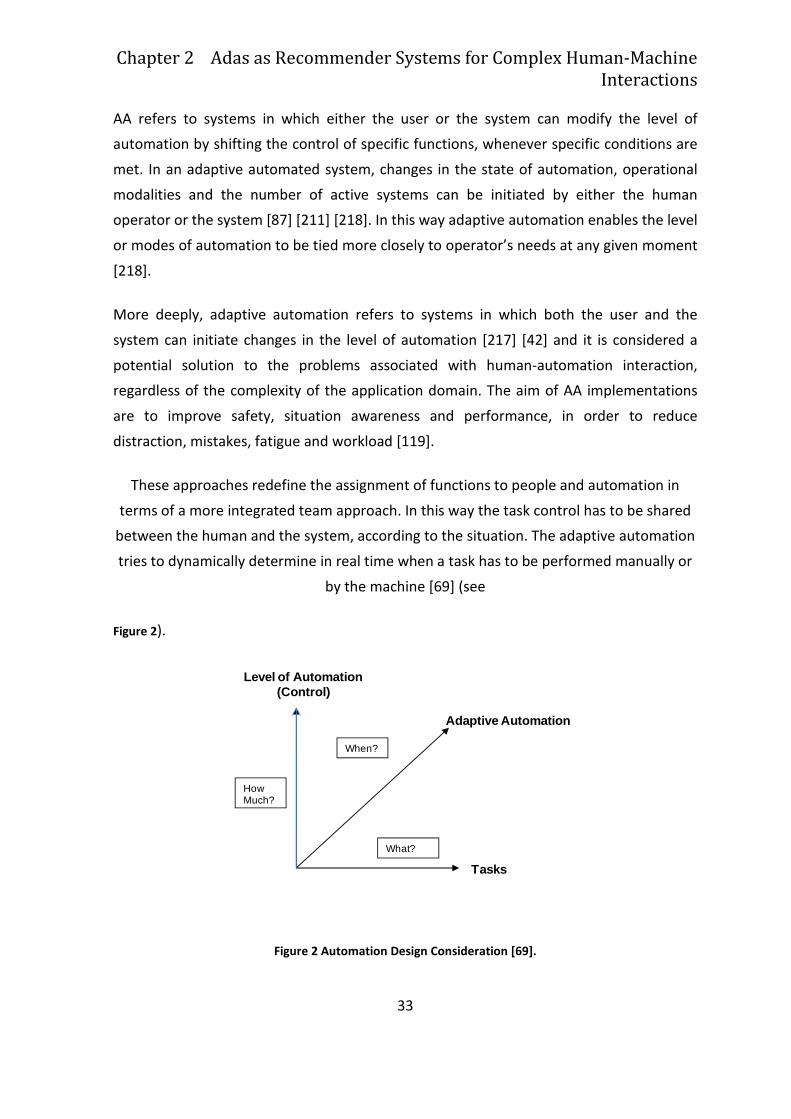
These approaches redefine the assignment of functions to people and automation in
terms of a more integrated team approach. In this way the task control has to be shared
between the human and the system, according to the situation. The adaptive automation
tries to dynamically determine in real time when a task has to be performed manually or
by the machine [69] (see
Figure 2).
Figure 2 Automation Design Consideration [69].
Adaptive Automation
HowMuch?
When?
What?
Level of Automation(Control)
Tasks
2.3 Matching the user behavior model with adaptive automation
strategies: toward an adaptive driver assistance system
34
Along the axes of figure 1 are shown two orthogonal and complementary approaches:
one approach (Level of Automation - Control) tries to find to optimisation in the
assignment of control between the human and automated system by keeping both
involved in system operation. The other (Adaptive Automation, AA, or Dynamic Function
Allocation, DFA) illustrates how the control must pass back and forth between the human
and the automation over time, and seeks to find ways of using this to increase human
performance [69].
In an adaptive automated system, changes in the state of automation can be invoked by
either the human or the system [87] [211] [217], as a result adaptive automation enables
the level or modes of automation to be tied more closely to operator needs at any given
moment [217].
Human intention and actions, summarised in a user profile, are the parameters the
system uses to offer the correct solution or answer to the faced context. In this way it is
possible to improve the human performance that represent the crucial hearth of the
interaction in complex systems. Besides the operator is maintained in loop during the
system control, in order to avoid or reduce the out-of-the-loop performance. From the
literature analysis, some consolidate cognitive tools and practise for the adaptive
automation design come out [217]: Function allocation [89], Dynamic Function Allocation
[115], and Task Analysis.
Andy Clark [58] successfully depicted the technological relationship between human and
automated system: “humans have always been adept at dovetailing our minds and skills
to the shape of our current tools and aids. But when those tools and aids start dovetailing
back – when our technologies actively, automatically, and continually tailor themselves to
us just as we do to them – then the line between tool and human becomes flimsy
indeed”.
Automation refers to “systems or methods in which many of the processes of production
are automatically performed or controlled by autonomous machines or electronic
devices” [27]. Automation may be conceived as a tool, or resource, that allows the user at
performing a task that would be difficult or impossible to do without the help of machines
[27]. Therefore, automation can be conceived as the process of substituting some device
or machine for a human activity [192].
Chapter 2 Adas as Recommender Systems for Complex Human-Machine
Interactions
35
The literature also define automation with a 10 point scale, which describe step by step
the automation continuum of Levels1 (Levels of Automation - LoA)[191]. This approach
takes into account the control assignment of the system between the human and the
machine, focusing on the participation and the autonomy that humans and machines may
have in each task to be performed. In the Sheridan model the human machine interaction
is particularly stressed; the purpose is to find the best level that fits human needs, in
order to maximise the system performance and to optimize its use. Billings [25] focuses
instead his attention on automation at work: how automation may correctly perform
some activities or parts of them, how automation may interact with humans or support
them in their tasks. The author defines LoA in functional terms: a level of automation
corresponds to the set of function that an operator can autonomously control in a
standard situation united to system ability at providing answer and solutions, at acting
properly according to the proposed solution, and to check the results of its actions [42].
Tightly coupled with Billings definition are Rouse’s considerations [212]: the adaptive
automation provides variable levels of support to human control activities in complex
systems, according to the situation. Moreover, the situation is defined by the task
features and by the psychophysical status of human operator. As a consequence, the
human machine interaction should depend on what has to be automated, and on how
and when this should occur.
The importance of the operator’s psychophysical status is a crucial aspect examined by
Parasuraman et al. [187]: the AA is the best combination between human and system
abilities. This combination, or more properly integration, is leaded by a main decision
criterion: the operator mental workload.
There are several studies reviewing the performance effects of Dynamic Function
Allocation (DFA) in complex systems, specifically monitoring and psychomotor functions
[98] [116] [118] [188] [189] [217]. These studies brought into evidence that AA
significantly improves monitoring and tracking task performance in multiple task
scenarios, as compared to static automation and strictly manual control conditions.
1 This model (Parasuraman et al., 2000) is made of ten levels: 1) the computer offers no assistance: human must take all decisions and
actions; 2) the computer offers a complete set of decision/action alternatives, or 3) narrows the selection down to a few, or 4) suggests one alternative, 5) executes that suggestion if the human approves, or 6) allows the human a restricted time to veto before
automatic execution, or 7) executes automatically, then necessarily informs the human, and 8) informs the human only if asked, or 9) informs the human only if it, the computer, decides to 10) the computer decides everything, acts autonomously, ignoring the human.
2.3 Matching the user behavior model with adaptive automation
strategies: toward an adaptive driver assistance system
36
The Neuroergonomics approach to AA systems uses psychophysiological measures to
trigger changes in the state of automation. Studies have shown that this approach can
facilitate operator performance, starting different types of automation, in relation with
the context (system and operator). [218].
Less work has been conducted to establish the impact of AA on cognitive function
performance (e.g., decision-making) or to make comparisons of human-machine system
performance when AA is applied to various information processing functions [117].
Kaber and Riley [118] closed up defining adaptive automation as a programming or a pre-
definition of the control assignment between human and system, in order to improve the
human performance. Human performance is in fact a crucial aspect of the functioning of
complex system. As a consequence, the human operator should be involved in the control
task, in order to avoid the out-of-the-loop performance [42]. As stated by Norman [180],
without appropriate feedback people are indeed out-of-the-loop; they may not know if
their requests have been received, if the actions are being performed properly, or if
problems are occurring. Sharing the functions control is not only a matter of quantitative
task to accomplish, but it involves the responsibility of the whole operation execution.
The dynamic function allocation (DFA) is a peculiar aspect of AA [119]: it is the
assignment of the authority on specific functions to either the human operator or the
automated system, depending on the overall context (i.e. operator’s state and outer
conditions) and on a defined set of criteria. DFA should therefore be designed by taking
into account both the human and the system status, and considering strategies for
context recognition.
Focusing on the participation and the autonomy that humans and machines may have in
each task to be performed, several researches have been developed. Some researches
face the crucial issue of the authority that each part should have in controlling the
system. Historically, humans played the role of the supervisory control i.e. the machine
decides about the actions and the humans evaluate these decisions; depending on this
assessment, control on the actions is either regained by human operators or provided
[224]. In this effort a crucial role is played by the human skills and abilities and by the
systems natural limits [191]
Chapter 2 Adas as Recommender Systems for Complex Human-Machine
Interactions
37
There is a clear difference between the AA approach and the Level of Automation [42].
The traditional view of automation is a fixed and highly regulated process designed to
eliminate human interaction. AA is designed to expect and anticipate changes under
active control of a developer insteas, while maintaining precise control of all background
variables not currently of interest [120]. AA is based on the dynamic allocation of the
control of the whole task or of some parts, crossing along manual and automated phases.
The results of a mere use of levels of automation (LOA) is a static function assignment,
since the task level of automation is established in the design phase [115]. Through
adaptive automation, developers gain flexible control of parameters under study and
confidence as well as automatic control of the rest of their systems [120]. In this way,
adaptive automation can be considered as a design philosophy with a heavy impact on
the technological development. Rather than focusing on repetition of the same events,
adaptive automation focuses on flexible process design and rapid process development.
AA allows process development facilities to move beyond limited “automated
instrument” development into a more fully integrated “automated process,” in which
individual instruments become part of a universal, fully-automated cycle [120].
The design of complex systems supporting the operator situation awareness is the bridge
between human centred automation theory and adaptive automation techniques [119].
Since the human centred automation claims an acceptable workload and a good situation
awareness, then the adaptive automation is the vehicle for the reaching of these
purposes. Hence the AA can be defined as a kind of human centred automation. On this
hand there are empirical evidence on positive effects of AA on SA and workload [116], on
the other hand there is not a unique theory that give designer a general guideline suitable
for each application field, such as aviation, automotive, rails, tele-robotics and
manufacturing.
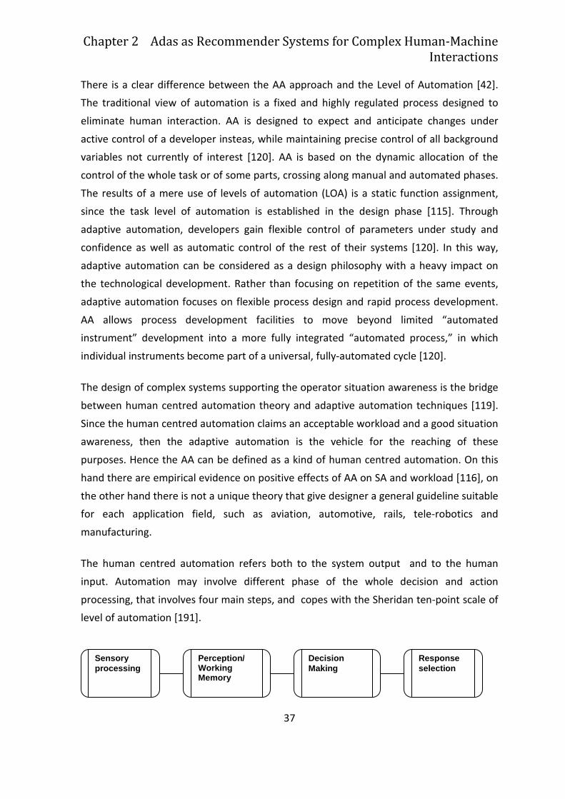
The human centred automation refers both to the system output and to the human
input. Automation may involve different phase of the whole decision and action
processing, that involves four main steps, and copes with the Sheridan ten-point scale of
level of automation [191].
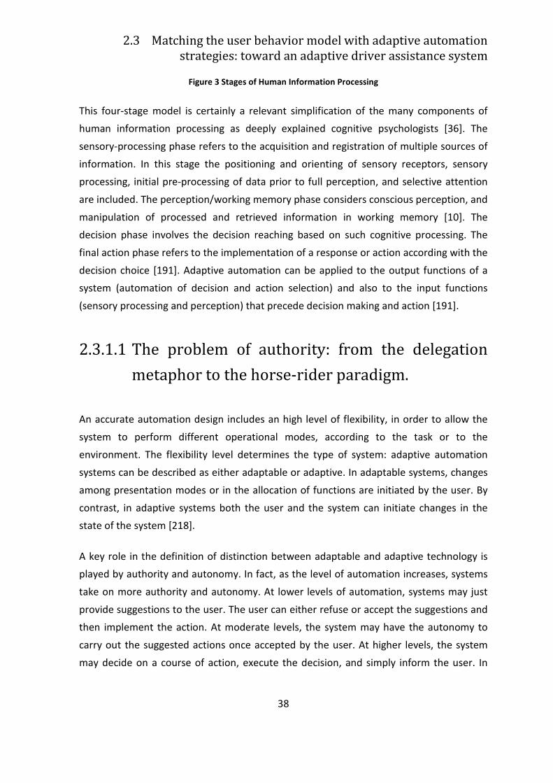
Perception/ Working Memory
Decision Making
Response selection
Sensory processing
2.3 Matching the user behavior model with adaptive automation
strategies: toward an adaptive driver assistance system
38
Figure 3 Stages of Human Information Processing
This four-stage model is certainly a relevant simplification of the many components of
human information processing as deeply explained cognitive psychologists [36]. The
sensory-processing phase refers to the acquisition and registration of multiple sources of
information. In this stage the positioning and orienting of sensory receptors, sensory
processing, initial pre-processing of data prior to full perception, and selective attention
are included. The perception/working memory phase considers conscious perception, and
manipulation of processed and retrieved information in working memory [10]. The
decision phase involves the decision reaching based on such cognitive processing. The
final action phase refers to the implementation of a response or action according with the
decision choice [191]. Adaptive automation can be applied to the output functions of a
system (automation of decision and action selection) and also to the input functions
(sensory processing and perception) that precede decision making and action [191].
2.3.1.1 The problem of authority: from the delegation
metaphor to the horse-rider paradigm.
An accurate automation design includes an high level of flexibility, in order to allow the
system to perform different operational modes, according to the task or to the
environment. The flexibility level determines the type of system: adaptive automation
systems can be described as either adaptable or adaptive. In adaptable systems, changes
among presentation modes or in the allocation of functions are initiated by the user. By
contrast, in adaptive systems both the user and the system can initiate changes in the
state of the system [218].
A key role in the definition of distinction between adaptable and adaptive technology is
played by authority and autonomy. In fact, as the level of automation increases, systems
take on more authority and autonomy. At lower levels of automation, systems may just
provide suggestions to the user. The user can either refuse or accept the suggestions and
then implement the action. At moderate levels, the system may have the autonomy to
carry out the suggested actions once accepted by the user. At higher levels, the system
may decide on a course of action, execute the decision, and simply inform the user. In
Chapter 2 Adas as Recommender Systems for Complex Human-Machine
Interactions
39
adaptive systems authority over the automatic process is shared. Both the operator and
the system can initiate changes in state of the automation [42].
There is some debate over who should have control over system changes, overall over
who should behave the final authority on the control process: some researchers believe
that humans should have the highest authority over the system, because s/he has the
final responsibility of the whole system behaviour. This position is supported by the
conviction that humans are more reliable and efficient in the resources and safety
management when they encompass the control over the automation change of state [28]
However there may be times when the operator will be not the best judge of when
automation is needed. Scerbo [218] argues that in some hazardous situations where the
operator is vulnerable, it would be extremely important for the system to have authority
to invoke automation, because, for example, operating environments change with time,
and it may not be easy for humans to make correct decision in a changed environment,
especially when available time or information is limited [106] or when operators are too
busy to make changes in automation [247]. The authority shared between humans and
machines becomes a question of decision during design.
It is important to notice that human and automation roles are structured as
complementary: one of the main approach to human interaction with complex system is
“delegation”, that is patterned on the kinds of interactions that a supervisor can have
with an intelligent trained subordinate. Human task delegation within a team is in fact an
example of adaptable system, “since the human supervisor can choose which tasks to
hand to a subordinate, can choose what and how much to tell the subordinate about how
(or how not) to perform the subtask s/he is assigned, can choose how much or how little
attention to devote to monitoring, approving, reviewing and correcting task performance,
etc.” [162].
Delegating a task to a subordinate (in this case the automation) means for the
subordinate to have at least a partial authority to determine how to perform that task.
Moreover a good subordinate may have opportunities to take initiative in order to
suggest tasks that need to be done or to propose information that may be useful [163].
The main difference between task delegation performed by a supervisor and task
allocation performed by a system designer is that the supervisor has more flexibility in
what when and how to delegate and better awareness of the task performance
2.3 Matching the user behavior model with adaptive automation
strategies: toward an adaptive driver assistance system
40
conditions. The system designer, instead, has to fix a relationship at design time for static
use in all context [163].
The variation of the quantity of control and authority is an important issue, because in the
case of emergency it may be needed to rapidly transfer the control, without distraction
from the outcome problem, as frequently occurs in time- and safety- critical situations, as
ADAS design show.
Despite of all the efforts to create a human-machine communication, there are no real
communication capabilities built into systems. As Norman states [181]: “Closer analysis
shows this to be a misnomer: there is no communication, none of the back-and-forth
discussion that characterizes true dialogue. Instead, we have two monologues. We issue
commands to the machine, and it, in turn, command us. Two monologues do not make a
dialogue”. The collaboration and communication failure by a even more powerful
technology becomes a very crucial point. Collaboration requires synchronisation and
trust, achievable only through experience and understanding [181].
The need of sharing trust and knowledge between humans and machines lead to the so
called H-Metaphor, that studies and tryes to reproduce the relationship between a horse
and its rider. The “horse-rider paradigm” is introduced at first time in 1990 by Connell and
Viola, then it has been developed by Flemish and colleagues [72], that named it “H-
metaphor” and faced also by Norman [181]. The “Horse-Rider paradigm” explains the
relation between human and automation like the relation that a rider establishes with
his/her horse: the human receives information about the actual system status through an
osmotic exchange with it. Human intention and actions become the parameters the
system uses to offer him the correct solution or answer to the faced context. In this way it
is possible to improve the human performance that represent the crucial hearth of the
interaction in complex systems. Besides the operator is maintained in loop during the
system control, in order to avoid or reduce the out-of-the-loop performance.
Although the adaptive automation is very promising, some problems are still unsolved, as
the identification of task features that determines the optimal level for the AA
implementation [42]. It has to be carefully taken into account the effects on the cognitive
and physically activities, specifying the best AA implementation for each activity. As well
human machine interfaces have to be studied in order to support correctly the AA [119].
Another difficult issues is about when AA should be invokes. It is needed to work in order
Chapter 2 Adas as Recommender Systems for Complex Human-Machine
Interactions
41
to address questions of periodic insertion of automation into manual task. “Research is
also needed to explore the interaction between adaptive automation and level of control
– how much automation needs to be employed may be a function of when it is
employed” [69]. It should be determined also how to implement AA, that is another
controversial matter. Many systems allow operators to start automation, but in critical
situations, the human may be [69]:
1. so overloaded as to make this an extra encumber,
2. incapacitated or unable to do so,
3. unaware that the situation calls for automated assistance,
4. a poor decision maker.
Otherwise leaving the system with the authority to turn itself on and off may be even
more problematic, as this forces the operator to passive accept the system decision [69].
The final authority may be traded flexibly and dynamically between humans and
automation, because there can be the cases in which automation should have the final
authority for ensuring the safety of the system [106].
There are also some side effects: despite of the wide advantages of automation such as
the increased capacity and productivity, reduction of small errors, manual workload and
mental fatigue, the relief from routine operations, and decrease of performance variation
due to individual differences, there are several drawbacks that must be taken into
account [43].
Since automation brings same changes in the task execution (i.e. setup and initialization),
in the cognitive demands (i.e. requirements for increased situational awareness), in the
people roles related to the system (i.e. relegating people to supervisory controllers).
Beside a decrease of job satisfaction automation lead to a lowered vigilance and an
increased mental workload, fault-intolerant systems, silent failures, false alarms. This
framework is strictly connected with other negative effects due to the human interaction
with the system: over-reliance, complacency, over trust and mistrust, manual deskilling
[197]. Nowadays the adaptive automation is claimed as the solution for the problems
inducted by the automation and can be successfully applied in the design of automotive
user interfaces that control automatic systems (ADAS) or partially adaptive systems
(PADAS).
2.3 Matching the user behavior model with adaptive automation
strategies: toward an adaptive driver assistance system
42
2.3.1.2 Design issues
In order to develop an adaptive system, some theoretical instruments guiding designers
in the preliminary phases are available, such as task analysis and function allocation that
both aim at matching the human abilities with the system ones, in order to automate the
tasks best suited to machines and to maintain as manual the functions best suited to
human [89]. The task analysis is namely a graphic representation (as flow chart) of tasks
and sub tasks that the operators may accomplish with the system. Once the basilar
functions have been founded, they will be allocated, in order to consider the
consequences of the match of functions with roles and scenarios. As Harrison, Johnson,
Wright [89] defined, a function is an activity that the man-machine system is required to
be capable of performing in order to achieve some result in the domain under
consideration. From this point of view it is possible to state that work systems perform
functions or units of work. Roles, instead, are more difficult to define. They make sense to
consider it as an activity that can be performed either by human or machine [89].
The critical issue is about deciding which functions are suitable to which rules, considering
different scenarios [42]. “A function may be separable from all roles, and technically
feasible and cost effective to automate, in which case the function may be totally
automated. Alternatively it is possible that the function maps entirely to one of the roles,
and is infeasible to automate, in which case the function is totally performed within that
role. In most cases however functions fit into neither category. In this situation the
function is to be partially automated” [89]. Functions and roles have to be set into one or
more scenarios.
The scenario development process involves several steps [42]:
1. identification of goals and objectives;
2. scenario definition, including specifications and development of needed model
elements and performance measures;
3. preparation of specific component models;
4. program specific performance measures;
5. scenario programming;
Chapter 2 Adas as Recommender Systems for Complex Human-Machine
Interactions
43
6. testing, upgrading and validating of the system on the chosen scenarios. In taking
into account the driving scenario, it has to be measured the driver’s competences
in tasks critical to performance and safety.
These concept can be clarified by an example belonging to the automotive domain.
Designing a preventive safety system, the driving scenario and its corresponding
manoeuvres have been broken down into functions and sub-functions in order to outline
which functions have to be performed manually, automatically or both. Secondly, system
and driver’s role have been combined with functions in order to outline which functions
suite best to which roles, considering the given scenarios. The scenarios have been
selected in order to measure the driver workload and situation awareness.
Consequentially the selected scenario shows the whole behaviour of the system, along
the seven LoA implemented [42].
2.3.1.3 Adaptive Automation application in the design of
preventive safety systems
One of the most promising application field of the adaptive automation design principles
is the automotive domain, where the automation in a safety tool for the design of
preventive safety systems. Particularly, the systems that foresee the integration of
automation elements into the driving task (i.e. the ACC, adaptive cruise control) are
studied by the information ergonomics [44], that deals with the improvement of
signalling and command devices whose efficient information is often crucial. It is
specifically the case of in-vehicle information systems (IVIS), that nowadays include also
the nomadic devices, like pocket pc and mobile phones; of the new integrated
dashboards, that show the driver, apart from traditionally information (such as
speedometer, odometer, rev counter, etc.), other information about the trip
(instantaneous consumption, fuel autonomy, covered distance, direction to follow, etc.);
of innovative commands like haptic devices or vocal commands.
The solution offered by AA can be applied not only to the automatic functions but also to
the user interface that manage them. There may be interesting solutions of dynamic
adaptation of interface to the external context and to the user psychophysical condition
[42].

2.3 Matching the user behavior model with adaptive automation
strategies: toward an adaptive driver assistance system
44
It comes into evidence the importance of the design of in-vehicle interfaces to carefully
evaluate which kind of information to take into account. From the human side the choose
is among visual, auditory, and haptic information. From the automation side the choose is
among psychophysical information: i.e. workload, situation awareness, distraction, ecc.
45
Chapter 3
Reasons, aims and methods to study
driver distraction
3.1 Driver distraction problem
Driver distraction is a well-known road safety issue. Despite of this the research is still at
the beginning: distraction is poorly defined, and theories and models of the mechanisms
and features that characterize it are limited. For example there is not a universally agreed
taxonomy of sources of all potential and actual distraction, that may occur inside and
outside the vehicle. Little is known about patterns of driver performance, individually and
in combination. The relationship between performance degradation, crash frequency,
and crash risk is little understood. Moreover there is little practical guidance on how to
align and prioritize research to support the development of effective distraction
prevention and mitigating strategies. It is needed to pay attention to the design of a road
transport system that minimizes driver exposure to avoidable sources of distraction. Such
a system would mitigate the effects of distraction and tolerate the consequences of
distraction thanks to a better road and vehicle design [207].
In this chapter we will present firstly an overview of distraction theory, through a critical
literature analysis aimed at the definition of a distraction model that may be effectively
implemented with machine learning approaches as it will be discussed in paragraphs 5.2
and 5.2.1.

3.1 Driver distraction problem
46
Secondly we will present a critical literature analysis of Machine Learning techniques
adopted to model driver’s distraction and behavior, with particular attention to our
research experience and findings
.
47
3.2 The background of driving distractions:
foundations and definitions
In recent years, we come to hear more and more regarding the problem of distraction,
nevertheless. there is no generally accepted definition of distraction. The most prominent
discordance is about the inclusion or not in the definition of the whole cognitive concept,
so that distraction is identified or limited exclusively to visual distraction. In the following,
several definitions of distraction are presented, in order to identify the most relevant
aspects.
Generally speaking, distraction is a “Diversion of attention away from activities required
for safe driving due to some event, activity, object or person, within or outside the
vehicle”[14].
Ranney, Garrott and Goodman [201] specify that any distraction from rolling down a
window, over adjusting a mirror, tuning a radio to using a cell phone can contribute to a
crash.
More in details, the literature identifies four type of distraction [123]:
1. Visual (e.g. looking away from roadway)
2. Auditory (e.g. responding to ringing cell phone)
3. Biomechanical (e.g. adjusting CD player)
4. Cognitive (e.g. lost in thought).
Author concern is about the cognitive category of distraction, that may be misleading,
because it implies that the other types of distraction presented here are not cognitive. In
particular, to be “lost in thought” means that the driver focuses its attention on his/her
own internal thoughts, instead of concentrating on the driving task [201]. But s/he is not
distracted by something external. Nevertheless it make sense to consider that each kind
of distraction, for example due to a secondary task, always implies a cognitive activity. In
this case the driver is attending both the driving task and the secondary one, with a likely
degradation in the driving performance.
3.2 The background of driving distractions: foundations and definitions
48
Stutts, Reinfurt, Staplin and Rodgman [230] as well as Stutts et al. [229] highlight a further
aspect of distraction: as it has been already explained, it occurs when the driver is
delayed in recognition of information needed to safely accomplish the driving task
because of some event or activity, object or person (both inside and outside the vehicle).
In this case, the presence of a triggering event discriminates a distracted driver from one
who is simply inattentive or “lost in thought”.
Green [80] examines the distractor’s role: something diverts and retains the driver’s
attention. That means the attention “is pulled away” instead of being redirected
voluntarily. But in this way, secondary tasks, which are performed while the driver
consciously tries to distribute his/her attention between the driving task and the
secondary task should be excluded [123].
Considering the exiting literature Tasca [237] argues that distraction happens when there
is:
• A voluntary or involuntary diversion of attention from primary driving tasks not
related to impairment (from alcohol/drugs, fatigue or a medical condition).
• Diversion occurs because the driver is:
o performing an additional task (or tasks) or
o temporarily focusing on an object, event or person not related to primary
driving tasks.
• Diversion reduces a driver’s situational awareness, decision-making and/or
performance resulting in any of the following outcomes:
o collision
o near-miss
o corrective action by the driver and/or another road user.
Following this definition, voluntary secondary task are still included, but the condition
“lost in thought” seem to be excluded. Moreover the driver that even if inattentive,
doesn’t cause a collision, a near miss or a corrective action, is not considered as distracted
[123].
All the abovementioned definitions are reported in the web site of the “Distracted Driving
Conference”, held in Toronto in October 2005, whose aim was that of converging toward
a exhaustive definition of distraction [123]. The following definition of distraction was
suggested [94]:
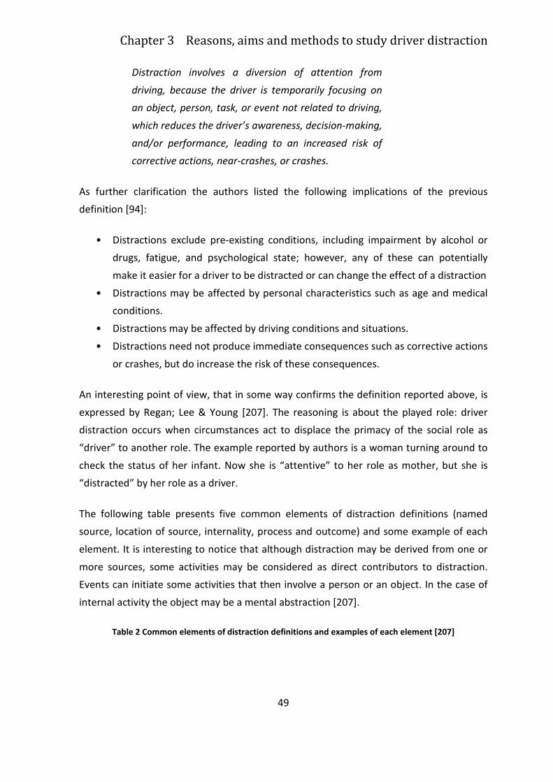
Chapter 3 Reasons, aims and methods to study driver distraction
49
Distraction involves a diversion of attention from
driving, because the driver is temporarily focusing on
an object, person, task, or event not related to driving,
which reduces the driver’s awareness, decision-making,
and/or performance, leading to an increased risk of
corrective actions, near-crashes, or crashes.
As further clarification the authors listed the following implications of the previous
definition [94]:
• Distractions exclude pre-existing conditions, including impairment by alcohol or
drugs, fatigue, and psychological state; however, any of these can potentially
make it easier for a driver to be distracted or can change the effect of a distraction
• Distractions may be affected by personal characteristics such as age and medical
conditions.
• Distractions may be affected by driving conditions and situations.
• Distractions need not produce immediate consequences such as corrective actions
or crashes, but do increase the risk of these consequences.
An interesting point of view, that in some way confirms the definition reported above, is
expressed by Regan; Lee & Young [207]. The reasoning is about the played role: driver
distraction occurs when circumstances act to displace the primacy of the social role as
“driver” to another role. The example reported by authors is a woman turning around to
check the status of her infant. Now she is “attentive” to her role as mother, but she is
“distracted” by her role as a driver.
The following table presents five common elements of distraction definitions (named
source, location of source, internality, process and outcome) and some example of each
element. It is interesting to notice that although distraction may be derived from one or
more sources, some activities may be considered as direct contributors to distraction.
Events can initiate some activities that then involve a person or an object. In the case of
internal activity the object may be a mental abstraction [207].
Table 2 Common elements of distraction definitions and examples of each element [207]
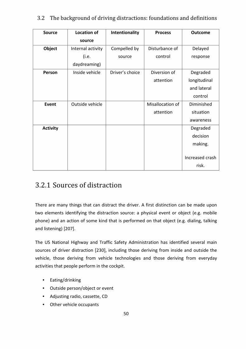
3.2 The background of driving distractions: foundations and definitions
50
Source Location of
source
Intentionality Process Outcome
Object Internal activity
(i.e.
daydreaming)
Compelled by
source
Disturbance of
control
Delayed
response
Person Inside vehicle Driver’s choice Diversion of
attention
Degraded
longitudinal
and lateral
control
Event Outside vehicle Misallocation of
attention
Diminished
situation
awareness
Activity Degraded
decision
making.
Increased crash
risk.
3.2.1 Sources of distraction
There are many things that can distract the driver. A first distinction can be made upon
two elements identifying the distraction source: a physical event or object (e.g. mobile
phone) and an action of some kind that is performed on that object (e.g. dialing, talking
and listening) [207].
The US National Highway and Traffic Safety Administration has identified several main
sources of driver distraction [230], including those deriving from inside and outside the
vehicle, those deriving from vehicle technologies and those deriving from everyday
activities that people perform in the cockpit.
• Eating/drinking
• Outside person/object or event
• Adjusting radio, cassette, CD
• Other vehicle occupants
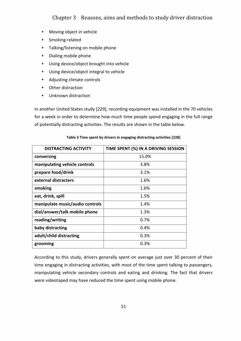
Chapter 3 Reasons, aims and methods to study driver distraction
51
• Moving object in vehicle
• Smoking related
• Talking/listening on mobile phone
• Dialing mobile phone
• Using device/object brought into vehicle
• Using device/object integral to vehicle
• Adjusting climate controls
• Other distraction
• Unknown distraction
In another United States study [229], recording equipment was installed in the 70 vehicles
for a week in order to determine how much time people spend engaging in the full range
of potentially distracting activities. The results are shown in the table below.
Table 3 Time spent by drivers in engaging distracting activities [228]
DISTRACTING ACTIVITY TIME SPENT (%) IN A DRIVING SESSION
conversing 15.0%
manipulating vehicle controls 3.8%
prepare food/drink 3.1%
external distracters 1.6%
smoking 1.6%
eat, drink, spill 1.5%
manipulate music/audio controls 1.4%
dial/answer/talk mobile phone 1.3%
reading/writing 0.7%
baby distracting 0.4%
adult/child distracting 0.3%
grooming 0.3%
According to this study, drivers generally spent on average just over 30 percent of their
time engaging in distracting activities, with most of the time spent talking to passengers,
manipulating vehicle secondary controls and eating and drinking. The fact that drivers
were videotaped may have reduced the time spent using mobile phone.
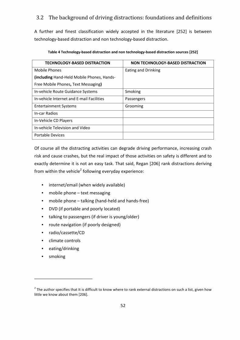
3.2 The background of driving distractions: foundations and definitions
52
A further and finest classification widely accepted in the literature [252] is between
technology-based distraction and non technology-based distraction.
Table 4 Technology-based distraction and non technology-based distraction sources [252]
TECHNOLOGY-BASED DISTRACTION NON TECHNOLOGY-BASED DISTRACTION
Mobile Phones
(including Hand-Held Mobile Phones, Hands-
Free Mobile Phones, Text Messaging)
Eating and Drinking
In-vehicle Route Guidance Systems Smoking
In-vehicle Internet and E-mail Facilities Passengers
Entertainment Systems Grooming
In-car Radios
In-Vehicle CD Players
In-vehicle Television and Video
Portable Devices
Of course all the distracting activities can degrade driving performance, increasing crash
risk and cause crashes, but the real impact of those activities on safety is different and to
exactly determine it is not an easy task. That said, Regan [206] rank distractions deriving
from within the vehicle2 following everyday experience:
• internet/email (when widely available)
• mobile phone – text messaging
• mobile phone – talking (hand-held and hands-free)
• DVD (if portable and poorly located)
• talking to passengers (if driver is young/older)
• route navigation (if poorly designed)
• radio/cassette/CD
• climate controls
• eating/drinking
• smoking
2 The author specifies that It is difficult to know where to rank external distractions on such a list, given how
little we know about them [206].
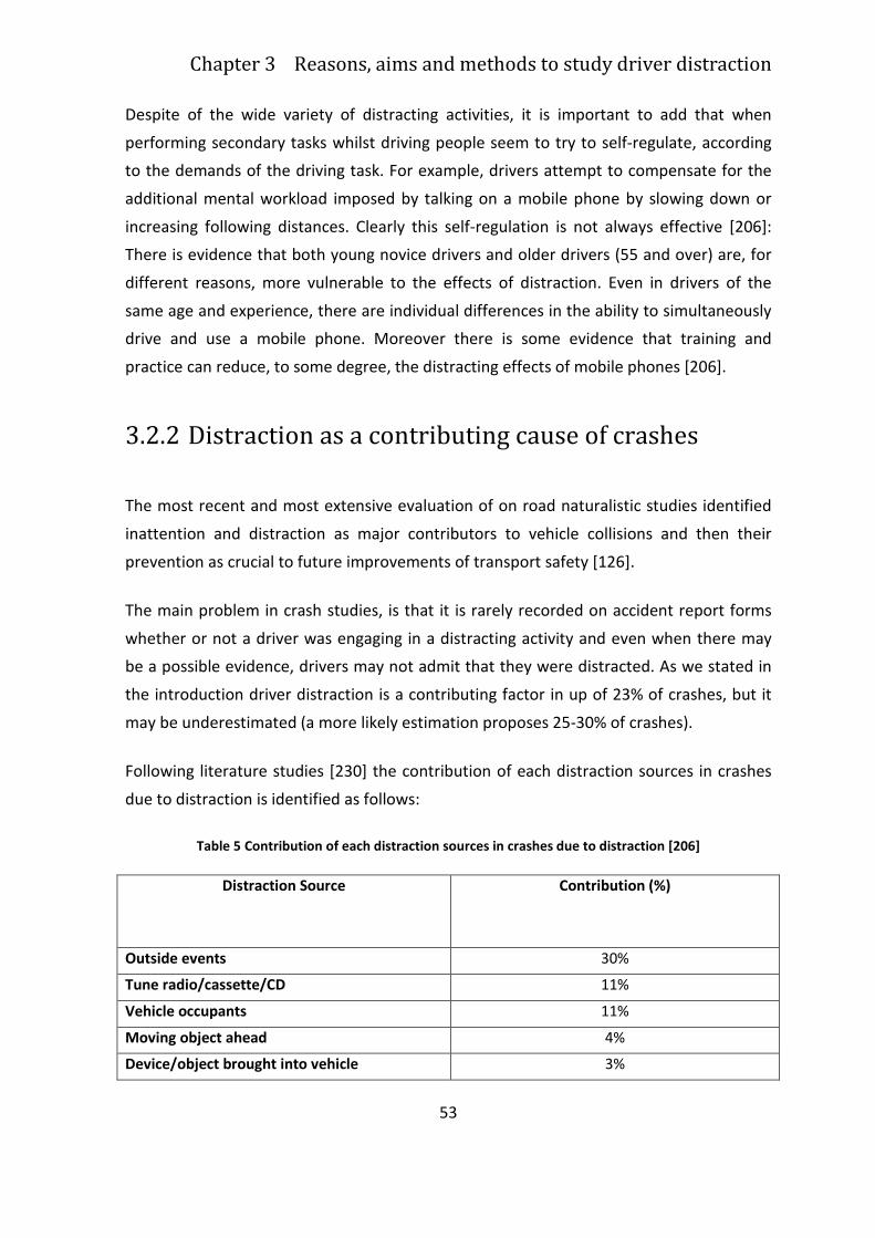
Chapter 3 Reasons, aims and methods to study driver distraction
53
Despite of the wide variety of distracting activities, it is important to add that when
performing secondary tasks whilst driving people seem to try to self-regulate, according
to the demands of the driving task. For example, drivers attempt to compensate for the
additional mental workload imposed by talking on a mobile phone by slowing down or
increasing following distances. Clearly this self-regulation is not always effective [206]:
There is evidence that both young novice drivers and older drivers (55 and over) are, for
different reasons, more vulnerable to the effects of distraction. Even in drivers of the
same age and experience, there are individual differences in the ability to simultaneously
drive and use a mobile phone. Moreover there is some evidence that training and
practice can reduce, to some degree, the distracting effects of mobile phones [206].
3.2.2 Distraction as a contributing cause of crashes
The most recent and most extensive evaluation of on road naturalistic studies identified
inattention and distraction as major contributors to vehicle collisions and then their
prevention as crucial to future improvements of transport safety [126].
The main problem in crash studies, is that it is rarely recorded on accident report forms
whether or not a driver was engaging in a distracting activity and even when there may
be a possible evidence, drivers may not admit that they were distracted. As we stated in
the introduction driver distraction is a contributing factor in up of 23% of crashes, but it
may be underestimated (a more likely estimation proposes 25-30% of crashes).
Following literature studies [230] the contribution of each distraction sources in crashes
due to distraction is identified as follows:
Table 5 Contribution of each distraction sources in crashes due to distraction [206]
Distraction Source Contribution (%)
Outside events 30%
Tune radio/cassette/CD 11%
Vehicle occupants 11%
Moving object ahead 4%
Device/object brought into vehicle 3%
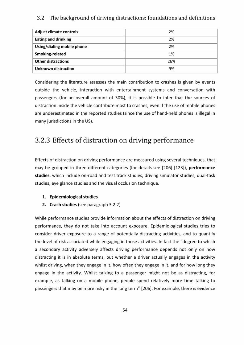
3.2 The background of driving distractions: foundations and definitions
54
Adjust climate controls 2%
Eating and drinking 2%
Using/dialing mobile phone 2%
Smoking-related 1%
Other distractions 26%
Unknown distraction 9%
Considering the literature assesses the main contribution to crashes is given by events
outside the vehicle, interaction with entertainment systems and conversation with
passengers (for an overall amount of 30%), it is possible to infer that the sources of
distraction inside the vehicle contribute most to crashes, even if the use of mobile phones
are underestimated in the reported studies (since the use of hand-held phones is illegal in
many jurisdictions in the US).
3.2.3 Effects of distraction on driving performance
Effects of distraction on driving performance are measured using several techniques, that
may be grouped in three different categories (for details see [206] [123]), performance
studies, which include on-road and test track studies, driving simulator studies, dual-task
studies, eye glance studies and the visual occlusion technique.
1. Epidemiological studies
2. Crash studies (see paragraph 3.2.2)
While performance studies provide information about the effects of distraction on driving
performance, they do not take into account exposure. Epidemiological studies tries to
consider driver exposure to a range of potentially distracting activities, and to quantify
the level of risk associated while engaging in those activities. In fact the “degree to which
a secondary activity adversely affects driving performance depends not only on how
distracting it is in absolute terms, but whether a driver actually engages in the activity
whilst driving, when they engage in it, how often they engage in it, and for how long they
engage in the activity. Whilst talking to a passenger might not be as distracting, for
example, as talking on a mobile phone, people spend relatively more time talking to
passengers that may be more risky in the long term” [206]. For example, there is evidence
Chapter 3 Reasons, aims and methods to study driver distraction
55
from epidemiological research that smokers and young novice drivers who carry their
peers as passengers, are also at increased risk of crashing.
In the following paragraphs the effects of some crucial distraction source on driver
performance are reported.
3.2.3.1 Mobile Phones
In particular, according to a review of the mobile phone literature [252] concluded that
the use of mobile phones, both hand-held and hands-free, impairs the following driving
performance measures performance in several ways:
• maintenance of lane position;
• maintenance of appropriate and predictable speed;
• maintenance of appropriate following distances from vehicles in front;
• reaction times;
• judgement and acceptance of safe gaps in traffic;
• detection/awareness of traffic signals
• general awareness of other traffic, increasing mental workload, stress and
frustration
• visual field of view, which has been shown to be correlated with increased crash
involvement
3.2.3.2 Navigation systems
Generally, navigation systems, if well designed, are able to reduce mental navigation
workload and the distraction associated with using paper maps and street signs to
navigate.
On the other hand, these systems are distracting if they allow drivers at entering
destination information while the vehicle is in motion and if they provide visual guidance,
especially complex guidance information, without any accompanying voice guidance, but
nowadays systems incorporate a lock out feature which prevents the driver from entering
a destination whilst the vehicle is in motion or travelling above a certain speed. Even
3.2 The background of driving distractions: foundations and definitions
56
systems that allow the driver to enter destination information using their voice rather
than manually have been shown to be distracting [206].
The distracting impact of the worst designed route navigation systems can be compared
to conventional navigation using paper maps.
3.2.3.3 Email
Retrieving, reading and responding to email messages, even if using voice commands,
increases reaction times to a braking lead vehicle and an increase in subjective estimates
of mental workload. Drivers are also able to compensate the increased workload, but
anyway they are slower to brake in response to a braking lead vehicle and made less
corrective steering movements when distracted [206].
3.2.3.4 Entertainment Systems
The main focus about entertainment systems has been on the effects on driving
performance of interacting with radios, cassette players, CD players and, more recently,
DVD players [206].
The use of entertainment systems affects:
- lane control
- cognitive workload
- speed control
- detection of unexpected hazards
3.2.3.5 Everyday Activities
Also everyday activities that may usually seem inconsequential can affect distraction,
such as eating, drinking, smoking and talking to passengers. Eating and drinking can cause
visual, physical and attentional distraction: a study found that eating a hamburger was as
distracting as dialing a mobile phone using voice commands [109]. Smoking has the
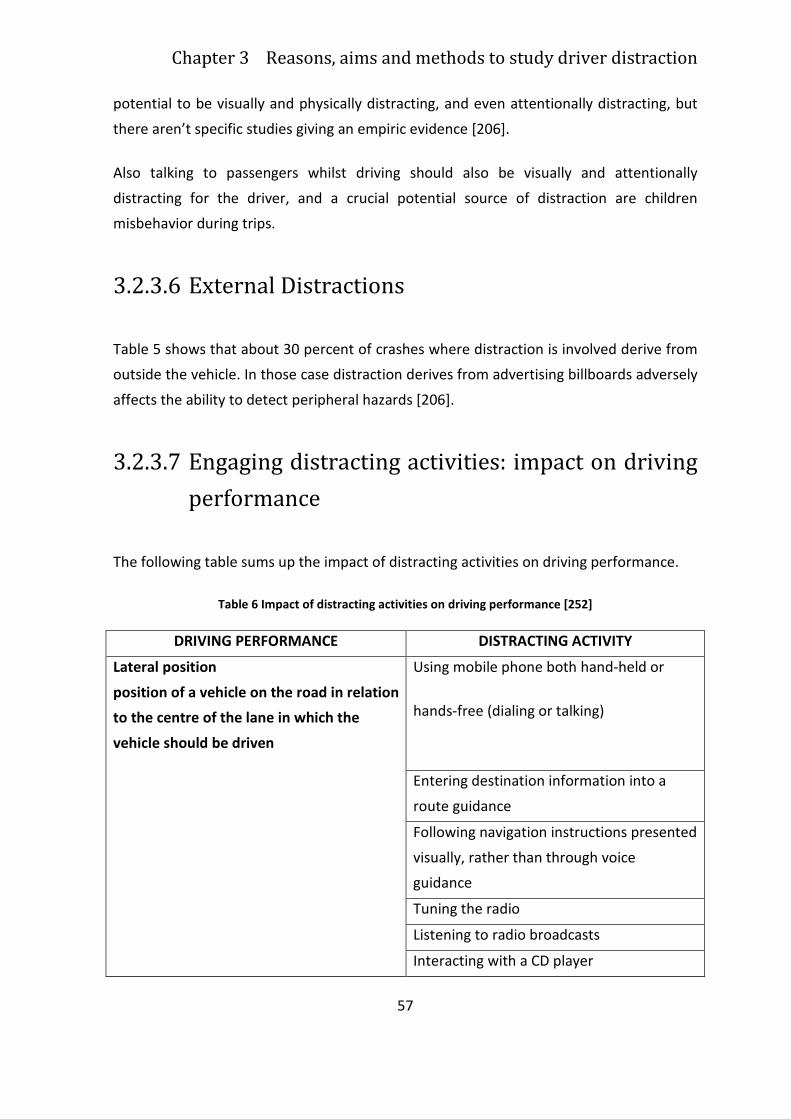
Chapter 3 Reasons, aims and methods to study driver distraction
57
potential to be visually and physically distracting, and even attentionally distracting, but
there aren’t specific studies giving an empiric evidence [206].
Also talking to passengers whilst driving should also be visually and attentionally
distracting for the driver, and a crucial potential source of distraction are children
misbehavior during trips.
3.2.3.6 External Distractions
Table 5 shows that about 30 percent of crashes where distraction is involved derive from
outside the vehicle. In those case distraction derives from advertising billboards adversely
affects the ability to detect peripheral hazards [206].
3.2.3.7 Engaging distracting activities: impact on driving
performance
The following table sums up the impact of distracting activities on driving performance.
Table 6 Impact of distracting activities on driving performance [252]
DRIVING PERFORMANCE DISTRACTING ACTIVITY
Lateral position
position of a vehicle on the road in relation
to the centre of the lane in which the
vehicle should be driven
Using mobile phone both hand-held or
hands-free (dialing or talking)
Entering destination information into a
route guidance
Following navigation instructions presented
visually, rather than through voice
guidance
Tuning the radio
Listening to radio broadcasts
Interacting with a CD player
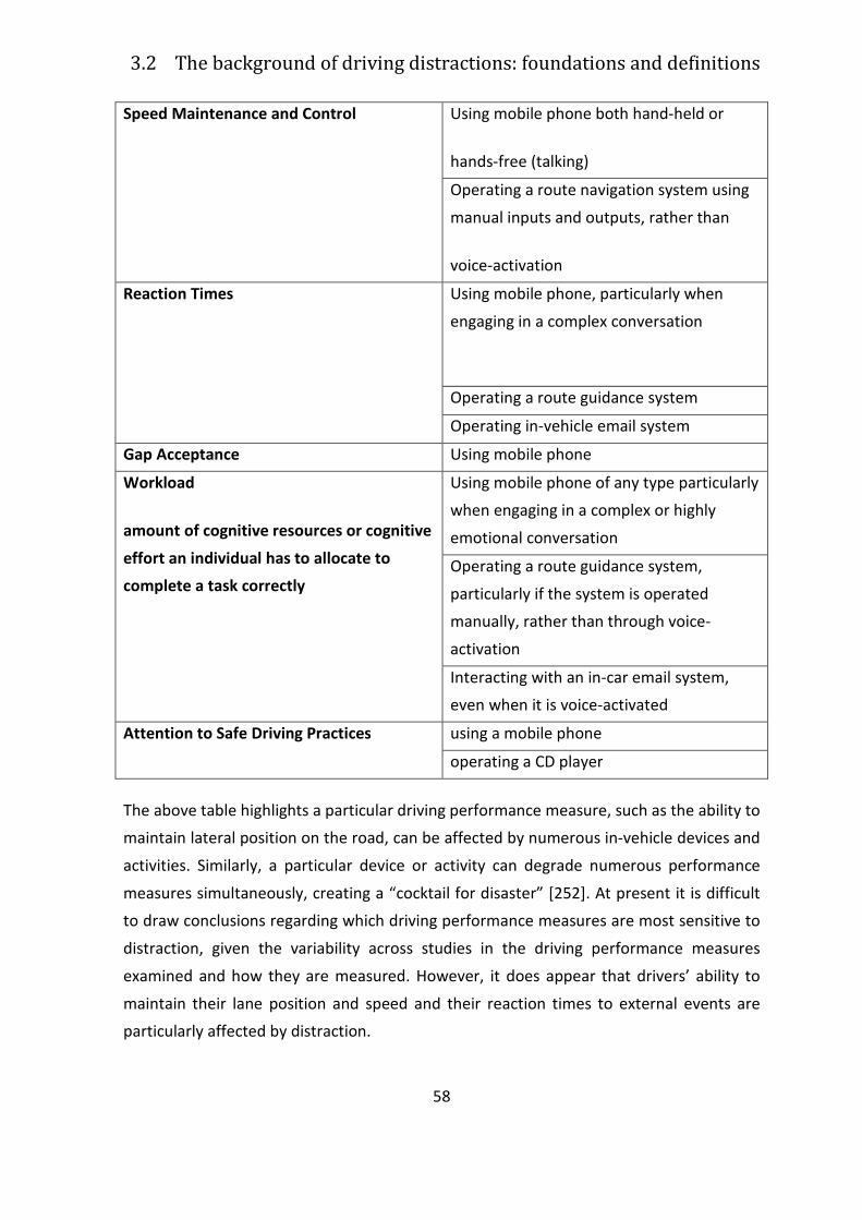
3.2 The background of driving distractions: foundations and definitions
58
Speed Maintenance and Control Using mobile phone both hand-held or
hands-free (talking)
Operating a route navigation system using
manual inputs and outputs, rather than
voice-activation
Reaction Times Using mobile phone, particularly when
engaging in a complex conversation
Operating a route guidance system
Operating in-vehicle email system
Gap Acceptance Using mobile phone
Workload
amount of cognitive resources or cognitive
effort an individual has to allocate to
complete a task correctly
Using mobile phone of any type particularly
when engaging in a complex or highly
emotional conversation
Operating a route guidance system,
particularly if the system is operated
manually, rather than through voice-
activation
Interacting with an in-car email system,
even when it is voice-activated
Attention to Safe Driving Practices using a mobile phone
operating a CD player
The above table highlights a particular driving performance measure, such as the ability to
maintain lateral position on the road, can be affected by numerous in-vehicle devices and
activities. Similarly, a particular device or activity can degrade numerous performance
measures simultaneously, creating a “cocktail for disaster” [252]. At present it is difficult
to draw conclusions regarding which driving performance measures are most sensitive to
distraction, given the variability across studies in the driving performance measures
examined and how they are measured. However, it does appear that drivers’ ability to
maintain their lane position and speed and their reaction times to external events are
particularly affected by distraction.
Chapter 3 Reasons, aims and methods to study driver distraction
59
3.2.3.8 Measurement of driving distraction
Numerous measures and techniques have been employed to determine driver
distraction. These measures range from high-tech equipment such as advanced driving
simulators, able of measuring a range of driving performance measures, to relatively
“low-tech” measures designed to measure specific aspects of distraction, such as the
visual occlusion technique [252].
The literature identifies the following scientific techniques for measuring distraction:
• on-road and test track studies;
• driving simulator studies;
• dual-task studies;
• eye glance monitoring studies;
• the visual occlusion method;
• the peripheral detection task; and
• the 15 Second Rule.
The technique, or sub-set of techniques to be employed during a test depends on the
particular aspect of the HMI to be assessed, and in particular on the form of distraction
(e.g., visual, physical etc) that is imposed on the driver by that aspect of the interface.
With the exception of on-road and test track studies and the 15-second rule, all of the
above methods are considered suitable for use in HMI evaluation studies. On-road studies
are obviously more dangerous to conduct and are less experimentally controlled than
simulator studies and there is some doubt in the literature about the validity of the 15-
second rule [252].
In the next paragraphs, a short explanation of each technique is presented..
3.2.3.9 On-road and Test Track Studies
One of the most realistic methods employed to measure distraction is the on-road
evaluation study: drivers are required to drive an instrumented vehicle for a specified
period of time. Driving performance data are collected using data loggers. Driving
performance while interacting with the various technologies is compared against a
3.2 The background of driving distractions: foundations and definitions
60
baseline measure, usually driving when not interacting with the devices [178]. This
method allows at gathering a vast amount of data in real-world conditions, but on the
other side it is time consuming (taking months or years to complete) and very expensive,
and thus is rarely used as a method to measure driver distraction.
Short-duration on-road evaluations or test-track studies are another suitable method to
represent real world driving and are often used to examine the distracting effects of
technologies [62]. This method does approximate real driving conditions and driving on a
closed test track reduce the safety risks associated with driving on actual roads [77].
However, the data collected can be affected by the effects of learning to use the
technologies and, in some cases, of being watched by an observer [178].
3.2.3.10 Driving Simulators
Research examining driver distraction often makes use of driving simulators, as they allow
to measure driving performance in a relatively realistic and safe driving environment,
allowing also safe multiple vehicle scenarios [252].
Driving simulators, however, vary substantially in their characteristics and this can affect
their realism and the validity of the results obtained. High-fidelity simulators offer a
realistic driving environment, with realistic components and layout, a colored, textured,
visual scene with roadside objects such as trees and signposts, and often have a motion
base. Low-fidelity simulators offer less realistic driving environments, usually with only
major markings (e.g., road line markings) reproduced in the visual scene and they are
often fixed-based [76]. The level of fidelity required by a simulator depends on the type of
research that has to be conducted. The literature suggests higher fidelity levels for
research where the results of the simulation will be used to draw conclusions about real-
world driving performance, for example the assessment of distraction using an in-vehicle
device [241].
Simulators allow greater experimental control, a large number of test conditions (i.e.
night and day, different weather conditions or road environments) and the cost of
modifying the cockpit of a simulator to address different research questions may be
significantly less than modifying an actual vehicle [205]. On the other side, driving
Chapter 3 Reasons, aims and methods to study driver distraction
61
simulators, particularly high-fidelity simulators, can be very expensive to install and
operate and are often much more expensive than other equipment used to measure
driver distraction (e.g., visual occlusion goggles) [205]. Another problem is discomfort or
sickness. Moreover, drivers’ behavior and the amount of cognitive resources used to
perform the experimental task with the simulator may differ significantly from their
behavior in real cars because there are no serious consequences that result from driving
errors in the simulator [77].
3.2.3.11 Dual-task Studies
Human beings only have a finite amount of cognitive processing resources to devote to
performing tasks. When the concurrent performance of two tasks exceeds this resource
pool, greater attention is devoted to one task and the performance of the other task is
adversely affected [204]. Dual-task studies assess the effects of performing one task on
the performance of another concurrent task. In the context of driver distraction, these
studies generally examine the effects of using an in-vehicle device (e.g., mobile phone), or
engaging in an activity (e.g., eating) on driving performance.
In order to gain a greater understanding of the distracting effects of in-vehicle
technologies, it is important for research on driver distraction to examine the
performance trade-offs between the driving and the distraction tasks [252].
A tool for measuring distraction is the Peripheral Detection Task (PDT). The PDT was
developed by van Winsum, Martens and Herland [242] to measure driver mental
workload and visual distraction. With this method, participants are required to perform a
series of tasks while detecting and responding to targets (e.g., lights) presented in the
periphery. As drivers become more distracted by the primary task, they respond slower
and fail to detect more PDT targets [183]. Performance of the PDT task therefore provides
a measure of how distracting the primary task is. PDT is a valid method for measuring the
level of visual and cognitive distraction afforded by in-vehicle technologies and driver
support systems [252].
3.2.3.12 Eye Glance Studies
3.2 The background of driving distractions: foundations and definitions
62
Visual behaviour while driving has been studied widely since the 1960’s [71]. Two
approaches for measuring visual demand or distraction are used: eye glance recordings
and the visual occlusion technique.
The eye glance technique measures visual behavior by recording the frequency and
duration of eye glances at particular objects in the driver’s visual field [71]. When drivers
perform a secondary task while driving, they usually complete this task through a series of
brief glances (1 to 2 seconds) at the object interspersed with glances at the roadway. Eye
glance studies record and measure the frequency and duration of glances towards the
secondary task which gives a measure of the total “eyes off road time”, and hence the
visual demand or interference associated with performing the task [86]. Total eyes-off-
road-time is a widely accepted and valid measure of the visual demand associated with
the performance of a secondary task and is highly correlated with the number of lane
excursions committed during secondary task performance [86].
Head and eye tracking allow for the real-time measurement of frequency and duration of
eye glances, scan paths, eye-closures, and over-the-shoulder head turns [252].
3.2.3.13 The Visual Occlusion Technique
Despite the advantages of new eye tracking equipment, these systems are often
expensive, time consuming and technically difficult to install and calibrate [71]. Visual
Occlusion is an alternative method for measuring the visual behavior of drivers. This
method is based on the assumption that drivers only need to observe the roadway part of
the time and the rest of the time is available for other purposes, such as interacting with
in-vehicle devices. With this technique, the driver’s vision is partially or fully occluded
through the use of a shield/visor or another similar device that opens and shuts at various
time intervals [252].
The aim of the method is to simulate an on-road situation where the driver is interacting
with a device while driving. The phase where the driver’s vision is occluded simulates the
time s/he is looking at the road, while the open phase represents the time that s/he is are
looking at the in-vehicle device. Using this method it is possible to evaluate whether an
in-vehicle task (e.g., tuning the radio) can be successfully carried out using only short
Chapter 3 Reasons, aims and methods to study driver distraction
63
glances or small amounts of visual attention (typically only 1 to 2 seconds) and if it can be
easily resumed after interruption [252].
With a few exceptions, literature studies confirmed that the visual occlusion technique is
a valid and reliable research tool for measuring the visual demand and distraction
associated with various in-vehicle devices and interfaces. It is relatively inexpensive and
easy to use and allows to evaluate also: task affordability, completion time, ease of
resumption after interruption and visual complexity, identifying HMI designs that are not
suitable for use while driving [252].
3.2.3.14 The 15-second Rule
The Society of Automotive Engineers (SAE) developed a standard for assessing the
maximum allowable level of distraction afforded by the use of in-vehicle navigation
systems [71]. This standard establishes a design limit for the total time required to input
information into navigation systems while the vehicle is in motion: “All navigation
functions that are accessible by the driver while the vehicle is in motion, shall have a
statistically measured total task time of less than 15 seconds” [71]. That is, if an in-vehicle
task can be completed within 15 seconds or less in a stationary vehicle, then that function
can be available to drivers while the vehicle is moving. Even if this standard was
developed to assess route navigation systems, it can also be applied to evaluate the
distraction afforded by any in-vehicle technology and it is really simple to use [252].
It should be remarked that static tests are not sufficient to identify tasks with significant
distraction potential. Moreover the 15-second rule fails to address issues of speed
maintenance or object detection, a failure to address whether and how a task may be
performed, and there are no baselines against which to measure driving performance
while completing a task [252].
3.2.4 Factors moderating the impact of distraction on
driving performances and safety
Understanding the factors that make drivers more or less vulnerable to the distracting
effects of competing activities is important when designing countermeasures to prevent
3.2 The background of driving distractions: foundations and definitions
64
and mitigate the effects of distraction [207]. In the following a number of these
moderating factors are examined.
3.2.4.1 Education
Governments, Police, motoring clubs and other relevant agencies should conduct
education and publicity campaigns to raise public awareness of the relative dangers
associated with engaging in distracting activities, how to minimize the effects of
distraction on themselves and others, and the penalties associated with engaging in
distracting activities where these exist [206].
3.2.4.2 Self-regulation
Little research addressed the question about whether and how drivers compensate for
any decrease in attention to the driving task (i.e. self-regulate) to maintain adequate
safety margins. In fact drivers actively adjust their driving behavior in response to
changing or competing task demands to maintain an adequate level of safe-driving [207].
Self-regulatory behavior can occur at a number of levels ranging from the strategic (for
ex. choosing not to use a mobile phone while driving) to the operational level (for ex.
reducing speed). At the highest level, drivers can moderate their exposure to risk by
choosing not to engage in potentially distracting activities while driving. At the tactical
and operational levels, research has shown that drivers attempt to reduce workload and
moderate their exposure to risk while engaging in secondary activities, through several
ways: by decreasing speed, by increasing inter-vehicular distance, and by reducing the
engagement in certain driving tasks, such as checking mirrors and instruments less
frequently. These self-regulatory behaviors can be viewed as examples of performance
trade-offs, because by performing these behaviors , drivers are changing the relative level
of priority that they assign to the driving task to accommodate performance of the
competing activity [207].
However, there are a number of factors that can influence a driver’s self-regulatory
strategies in response to a competing task, thus their vulnerability to being distracted by
this task. These factors are [207].
Chapter 3 Reasons, aims and methods to study driver distraction
65
• Driving task demand (increased traffic density, increased complexity if the traffic
environment)
• Driver characteristics (age and driving experience, task familiarity and practice)
• Driver state (fatigue, drowsiness, intoxication by drugs or alcohol, emotional state,
mood)
3.2.4.3 Training
Learner drivers need to be trained in how to safely manage distraction, being exposed to
distracting activities, such as talking to passengers. They need training in how to optimally
self-regulate their driving to reduce the effects of distraction; they need training in the
optimal modes in which to program and interact with systems (both on-board systems
and portable devices carried in and out of the vehicle). Furthermore they need to be
made self-aware and calibrated, through training, of the effects of distraction on their
driving performance; and passengers need to be trained in how to act as co-pilots rather
than backseat drivers by doing things for the driver and behaving in a manner which
minimizes distraction [206].
The problem with this approach is that it places the responsibility mainly on the drivers.
Norma described this as the “blame and train” philosophy [181]: whereby drivers are
blamed for the problem, they are punished appropriately and they should get more
training. This approach is difficult to justify because distraction does not occur
independently: it requires a distracter. Education and enforcement may not be able to
extinguish a driver’s reflexive diversion of attention to an in-vehicle display that is flashing
and beeping. On the other side drivers assume that any in-vehicle equipment can be used
while driving, even if it has a distracting potential.
3.2.4.4 Vehicle Design
The most effective way to reduce driver distraction deriving from technologies is to
ensure that the vehicle HMI is ergonomically designed, by both vehicle manufacturers
and the manufacturers of portable devices brought into the vehicle. It is crucial that
systems entering the market will meet certain minimum requirements, complying with
best practice human factors and ergonomic guidelines and standards. It is important that
3.2 The background of driving distractions: foundations and definitions
66
such an approach involves consultation with all relevant stakeholders: drivers, vehicle
manufacturers, aftermarket system suppliers, information service providers and road
authorities [206].
Unfortunately this approach leads to the “usability paradox” [146]: even the best
designed HMI may not solve the distraction problem because a well-designed device that
reduces distraction might encourage drivers to use it more frequently while driving.
A promising development is the “workload manager”, an on-board technology that uses
vehicle sensors to estimate driver workload and suppress mobile phone calls and other
sources of distraction until driver workload reduces [206] [46].
3.2.4.5 Road Design
Despite of distractions deriving from outside the vehicle are significant in number and
type, very little has be done to address this issue. The identification and ergonomic
assessment of traffic management activities, objects and events that could distract
drivers and degrade driving performance is crucial for the research in the driving
distraction domain. For example there is a need to develop a taxonomy of outside
distracting objects, events and activities, determining to what extent drivers are exposed
to these. There is a critical need, for vehicle manufacturers to enter into dialogue with
traffic engineers - to ensure that there are no incompatibilities in the design, timing and
number of traffic messages and signals affecting driver’s attention [206].
3.2.4.6 Research
There are a number of priority areas for research on driver distraction [206]:
• the definition and measurement of distraction;
• the quantification of crash risk;
• knowledge of driver exposure to distraction;
• knowledge of the self-regulatory strategies that drivers use to cope with
distraction;
• ergonomic design of the human-machine interface to limit distraction;
Chapter 3 Reasons, aims and methods to study driver distraction
67
• identifying levels of performance degradation due to distraction that constitute
safety impairment;
• knowledge on distraction deriving from outside the vehicle and the effects of
distraction on the performance and safety of pedestrians, motorcycle riders and
other road users.
3.2.5 Design and standardization
3.2.5.1 European approaches to principle, codes,
guidelines for In-Vehicle HMI
The European eSafety program
(http://ec.europa.eu/information_society/activities/esafety/index_en.htm ) is shaping
the approach to the design and assessment of both driver information and assistance
systems, which are expected to provide major contribution to accident reduction targets.
The eSafety Forum was established by the EC in close collaboration with industry,
industrial associations, and public sector stakeholders to address both safety and market
issues in the implementation of driver information and assistance systems as a
contribution to European road safety improvement targets
(http://www.esafetysupport.org/en/esafety_activities/esafety_forum/). The importance
of a safe HMI for IVIS and ADAS is a common understanding of all stakeholders.
The European Statemets of Principle (ESoP) on HMI provides high-level design guidelines
for information and communication systems that are usable and safe, taking full account
of the potential for driver distraction (“the system does not distract or visually entertain
the driver”) [59]. The guidelines include:
• Installation principles
• Information presentation principles
• Principle on interaction with displays and controls
• System behavior principles
• Principles on information about the system.
The principles are short statements summarizing specific and distinct HMI issues.
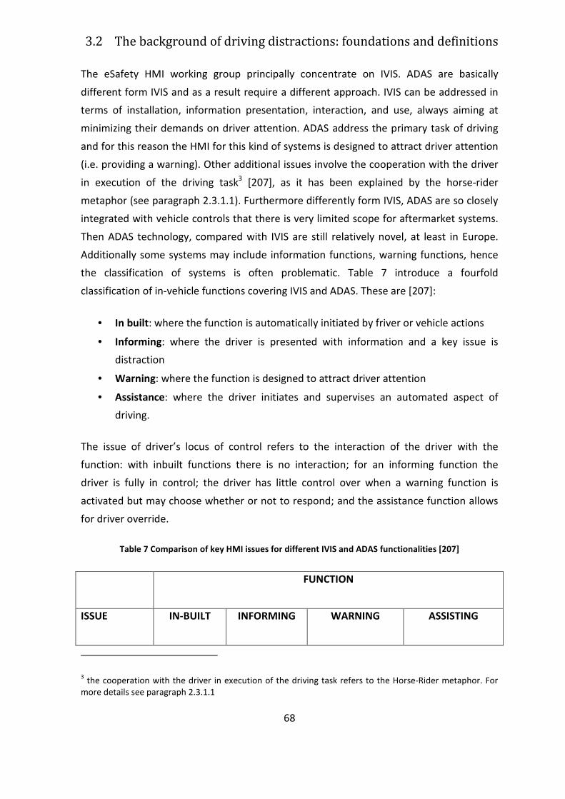
3.2 The background of driving distractions: foundations and definitions
68
The eSafety HMI working group principally concentrate on IVIS. ADAS are basically
different form IVIS and as a result require a different approach. IVIS can be addressed in
terms of installation, information presentation, interaction, and use, always aiming at
minimizing their demands on driver attention. ADAS address the primary task of driving
and for this reason the HMI for this kind of systems is designed to attract driver attention
(i.e. providing a warning). Other additional issues involve the cooperation with the driver
in execution of the driving task3 [207], as it has been explained by the horse-rider
metaphor (see paragraph 2.3.1.1). Furthermore differently form IVIS, ADAS are so closely
integrated with vehicle controls that there is very limited scope for aftermarket systems.
Then ADAS technology, compared with IVIS are still relatively novel, at least in Europe.
Additionally some systems may include information functions, warning functions, hence
the classification of systems is often problematic. Table 7 introduce a fourfold
classification of in-vehicle functions covering IVIS and ADAS. These are [207]:
• In built: where the function is automatically initiated by friver or vehicle actions
• Informing: where the driver is presented with information and a key issue is
distraction
• Warning: where the function is designed to attract driver attention
• Assistance: where the driver initiates and supervises an automated aspect of
driving.
The issue of driver’s locus of control refers to the interaction of the driver with the
function: with inbuilt functions there is no interaction; for an informing function the
driver is fully in control; the driver has little control over when a warning function is
activated but may choose whether or not to respond; and the assistance function allows
for driver override.
Table 7 Comparison of key HMI issues for different IVIS and ADAS functionalities [207]
FUNCTION
ISSUE IN-BUILT INFORMING WARNING ASSISTING
3 the cooperation with the driver in execution of the driving task refers to the Horse-Rider metaphor. For
more details see paragraph 2.3.1.1
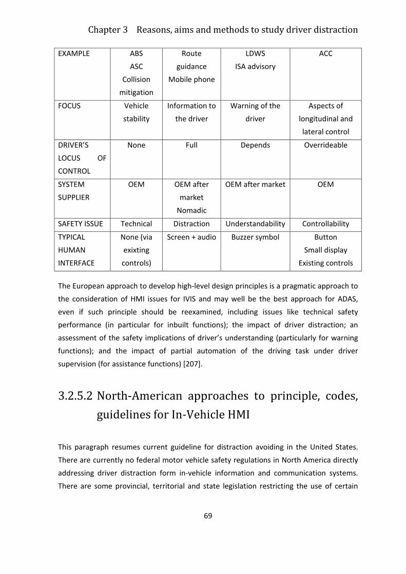
Chapter 3 Reasons, aims and methods to study driver distraction
69
EXAMPLE ABS
ASC
Collision
mitigation
Route
guidance
Mobile phone
LDWS
ISA advisory
ACC
FOCUS Vehicle
stability
Information to
the driver
Warning of the
driver
Aspects of
longitudinal and
lateral control
DRIVER’S
LOCUS OF
CONTROL
None Full Depends Overrideable
SYSTEM
SUPPLIER
OEM OEM after
market
Nomadic
OEM after market OEM
SAFETY ISSUE Technical Distraction Understandability Controllability
TYPICAL
HUMAN
INTERFACE
None (via
exixting
controls)
Screen + audio Buzzer symbol Button
Small display
Existing controls
The European approach to develop high-level design principles is a pragmatic approach to
the consideration of HMI issues for IVIS and may well be the best approach for ADAS,
even if such principle should be reexamined, including issues like technical safety
performance (in particular for inbuilt functions); the impact of driver distraction; an
assessment of the safety implications of driver’s understanding (particularly for warning
functions); and the impact of partial automation of the driving task under driver
supervision (for assistance functions) [207].
3.2.5.2 North-American approaches to principle, codes,
guidelines for In-Vehicle HMI
This paragraph resumes current guideline for distraction avoiding in the United States.
There are currently no federal motor vehicle safety regulations in North America directly
addressing driver distraction form in-vehicle information and communication systems.
There are some provincial, territorial and state legislation restricting the use of certain
3.2 The background of driving distractions: foundations and definitions
70
types of visual display devices, like television screens. In Canada instead there are nine
jurisdiction prohibiting the use of television screens in vehicles [246].
The first set of North American guidelines was published by the University of Michigan
Transportation Research Institute (UMTRI) in 1993 Suggested Human Factors Design
Guidelines for Driver Information Systems [82]. The guidelines were organized according
to the following topics [207]:
• Primary and secondary task design principles
• Guidelines for manual controls
• Spoken input, information needs, and dialogue guidelines
• Guidelines for auditory displays
• Navigation guidelines
• Traffic information
• Guidelines for in-vehicle warning systems
• Car phone guidelines
• Guidelines for system integration.
The UMTRI guidelines are based on the trade-off between comprehensiveness and ease
of finding critical information.
The most substantial guidelines for IVIS in north America is the U.S. Federal Highway
Adminsitration’s (FHWA) Human Factors Design Guidelines for Advanced Traveler
Information Systems (ATIS) and Commercial Vehicle Operations (CVO), published in 1998
[44]. This handbook was intended to address the information gap between new
automotive technologies and the availability of human factors guidelines. The guidelines
are organized according to the following topics [207]:
• General guidelines for displays (symbols, visual displays, auditory message length,
complexity of information, message style, head-up displays, individual
preferences, HMI design, alerts)
• General guidelines for controls (control type and coding, movement and
compatibility, keyboards, speech input)
• Routing and navigation guidelines
• Motorist service guidelines
• Route safety warning guidelines
Chapter 3 Reasons, aims and methods to study driver distraction
71
• Augmented signage information guidelines
• Guidelines for commercial vehicle related systems
• Tools designed for sensory allocation
The North-American guidelines places emphasis on navigation interfaces, providing also
physical ergonomics guidelines. Moreover they tend to deal with the traditional human
factors priorities, which are closely related to driver distraction, supporting the design of
HMI compatible with the driving task and the physical and cognitive capabilities of the
driver [207].
3.2.5.3 Japanese approaches to principle, codes,
guidelines for In-Vehicle HMI
Japan has been the world’s leader in making the navigation system technology pervasive
in the automotive industry. JAMA Guideline has been issued at an early stage of the
market introduction of navigation systems, in order to develop this technology carefully,
with a good balance of competition and collaboration [207].
The first version of JAMA (Japan Automobile Manufacturer’s Assosiation) guideline was
delivered in 1990. Today version 3.0 of JAMA guidelines is available [108].
The principles of JAMA Guideline version 3.0 are:
• Preferably, the display system is designed in such a way that its adverse effect on
safe driving will be minimized;
• The display system should be installed in such a position that driving operation
and the visibility of the forward field will not be obstructed
• The types of information to be provided by a display system should be such that
the driver’s attention will not be distracted from driving; information that is
essentially entertainment is to be avoided;
• The display system should be operated by the driver without adversely affecting
his or her driving performance
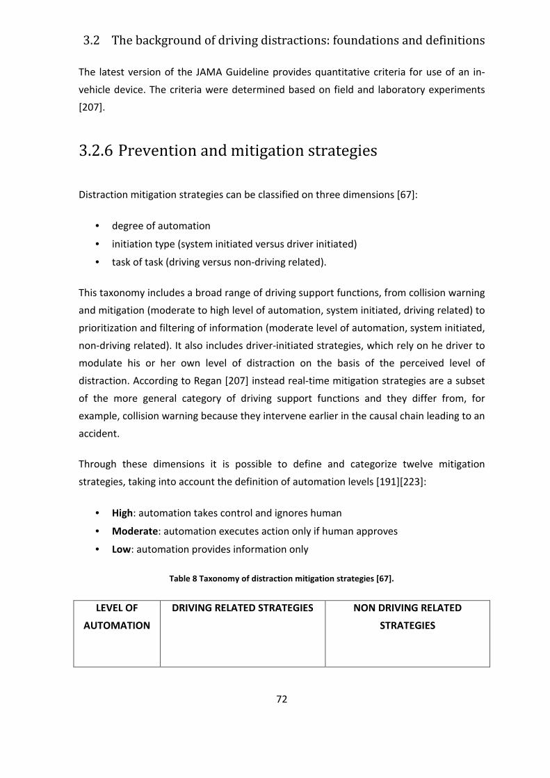
3.2 The background of driving distractions: foundations and definitions
72
The latest version of the JAMA Guideline provides quantitative criteria for use of an in-
vehicle device. The criteria were determined based on field and laboratory experiments
[207].
3.2.6 Prevention and mitigation strategies
Distraction mitigation strategies can be classified on three dimensions [67]:
• degree of automation
• initiation type (system initiated versus driver initiated)
• task of task (driving versus non-driving related).
This taxonomy includes a broad range of driving support functions, from collision warning
and mitigation (moderate to high level of automation, system initiated, driving related) to
prioritization and filtering of information (moderate level of automation, system initiated,
non-driving related). It also includes driver-initiated strategies, which rely on he driver to
modulate his or her own level of distraction on the basis of the perceived level of
distraction. According to Regan [207] instead real-time mitigation strategies are a subset
of the more general category of driving support functions and they differ from, for
example, collision warning because they intervene earlier in the causal chain leading to an
accident.
Through these dimensions it is possible to define and categorize twelve mitigation
strategies, taking into account the definition of automation levels [191][223]:
• High: automation takes control and ignores human
• Moderate: automation executes action only if human approves
• Low: automation provides information only
Table 8 Taxonomy of distraction mitigation strategies [67].
LEVEL OF
AUTOMATION
DRIVING RELATED STRATEGIES NON DRIVING RELATED
STRATEGIES
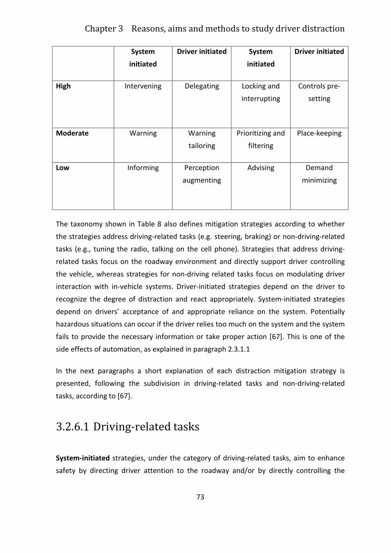
Chapter 3 Reasons, aims and methods to study driver distraction
73
System
initiated
Driver initiated System
initiated
Driver initiated
High Intervening Delegating Locking and
interrupting
Controls pre-
setting
Moderate Warning Warning
tailoring
Prioritizing and
filtering
Place-keeping
Low Informing Perception
augmenting
Advising Demand
minimizing
The taxonomy shown in Table 8 also defines mitigation strategies according to whether
the strategies address driving-related tasks (e.g. steering, braking) or non-driving-related
tasks (e.g., tuning the radio, talking on the cell phone). Strategies that address driving-
related tasks focus on the roadway environment and directly support driver controlling
the vehicle, whereas strategies for non-driving related tasks focus on modulating driver
interaction with in-vehicle systems. Driver-initiated strategies depend on the driver to
recognize the degree of distraction and react appropriately. System-initiated strategies
depend on drivers’ acceptance of and appropriate reliance on the system. Potentially
hazardous situations can occur if the driver relies too much on the system and the system
fails to provide the necessary information or take proper action [67]. This is one of the
side effects of automation, as explained in paragraph 2.3.1.1
In the next paragraphs a short explanation of each distraction mitigation strategy is
presented, following the subdivision in driving-related tasks and non-driving-related
tasks, according to [67].
3.2.6.1 Driving-related tasks
System-initiated strategies, under the category of driving-related tasks, aim to enhance
safety by directing driver attention to the roadway and/or by directly controlling the
3.2 The background of driving distractions: foundations and definitions
74
vehicle. They are namely: intervening (high automation), warning (moderate automation),
informing (low automation).
Intervening is characterized as the highest level of automation in this category, since it
refers to the system taking control of the vehicle and performing one or more driving-
related tasks during hazardous situations when the driver is too distracted to react in
time.
Warning alerts the driver to take a necessary action (e.g. a collision warning system).
Warning is considered a moderate level of automation compared to intervening because
the driver still behave the vehicle control.
Informing provides drivers with necessary information that they typically would not
observe if distracted (e.g. a speed limit indicator). This strategy is considered a low level
of automation since information is provided in a way that does not require any action
from the system.
In driving-related, driver-initiated strategies the driver mitigate distraction activating or
adjusting system controls that relate to the driving task. They are namely: delegating
(high automation), warning tailoring (moderate automation), perception augmenting (low
automation).
Delegating is driver initiation of an automatic vehicle control able to share the driving
task (e.g. adaptive cruise control, where the system assumes longitudinal control of the
vehicle). This strategy distributes the driver workload differently, and therefore may
reduce the attentional and biomechanical demands posed by the driving task.
The warning tailoring strategy refers to driver adjustment of the sensitivity of the
warning system depending on the distracting activities the driver expects to perform. This
differs from the warning strategy because driver input is required.
Perception augmenting provides driver information at the driver’s request. This can help
reduce the demands put on the driver to locate necessary information (e.g., driver’s
speed, posted speed) while driving, decreasing the level of distraction.
3.2.6.2 Non-Driving-related tasks
Chapter 3 Reasons, aims and methods to study driver distraction
75
Non-driving-related mitigation strategies aim to reduce driver distraction by limiting
attention paid to the in-vehicle system, rather than by directly influencing the driving
task. Like the driving-related strategies, these strategies can be subcategorized as system
initiated and driver initiated.
System-initiated, non-driving-related strategies work as follows: when the system
assesses that the driving performance is or will be significantly deteriorated, the system
will take action and change the nature of the non-driving-related task. They are namely:
locking and interrupting (high automation), prioritizing and filtering (moderate
automation), advising (low automation).
Locking and interrupting can be classified as high level automation in this category, since
interrupting discontinues the non-driving activities and locking locks out the system
associated with these activities when attention to the primary driving task is required.
Prioritizing and filtering information presented to the driver minimizes the number of
non-driving-related tasks that can be performed in high-load situations. For example,
under high-demand driving conditions, incoming calls can either be filtered (the phone is
not allowed to ring) or prioritized (only calls listed by the driver as highly important are
allowed).
Advising gives drivers feedback regarding the degree to which a non-driving task can
distract considering a demanding road or traffic situation. For example, a background
sound on a cellular telephone conversation could remind both parties that one is driving.
This sound could be modulated according to the driving situation.
The non-driving-related, driver-initiated strategies is based on the driver subjective
assessment of his/her degree of distraction.
They are namely: controls pre-setting (high automation), place keeping (moderate
automation), demand minimizing (low automation).
Controls pre-setting is classified as the highest level of automation for a driver-initiated
option in the non-driving related scenarios. For example, the driver can pre-set the radio
or CD player or the destination on navigational devices and in order to avoid modifying it
again while driving.
3.2 The background of driving distractions: foundations and definitions
76
Place keeping minimizes the demands of switching between the driving and the non-
driving-related tasks. Task switching involves directing attention from one task to another
(e.g. to stop talking on the cell phone to braking or to changing lane and then back to
talking on the cell phone). It is important to highlight that when a driver has to perform a
lot of simultaneously tasks, the task switching is more difficult, since it requires a certain
amount of attention.
Demand minimizing reduces attentional demands associated with non-driving-related
tasks by creating low-demand interfaces (e.g., using steering-wheel-mounted controls,
voice activation or hands-free
77
3.3 Machine Learning and User Modeling: the
lesson learned
"The field of machine learning was conceived with the bold objective to develop
computational methods that would implement various forms of learning, in particular
mechanisms capable of inducing knowledge from examples or data" [160][159].
ML, or Data Mining (DM), is the technology of searching large volumes of data for
unknown patterns, successfully applied in several domains such as business, healthcare,
etc. [149] [232]. Machine learning (ML) techniques have been applied to user modeling
problems for acquiring models of individual users interacting with an information system
and grouping them into communities or stereotypes with common interests. This
functionality is essential in order to have a useful and usable system that can modify its
behavior over time and for different users [138]. As showed from literature, there is a
trend in choosing machine learning techniques in the study of modeling of human
behaviors, that is non-deterministic and highly non-linear. ML methodologies are very are
very effective in discovering the underlying structure of data and, subsequently, generate
models that are not discovered from domain knowledge [253].
This form of knowledge induction is really suitable in problems that lack algorithmic
solutions, are ill-defined, or informally stated. Medical or technical diagnosis, visual
concept recognition, engineering design, material behavior, chess playing, or the
detection of interesting regularities in large data sets are examples of such problems.
Learning, like intelligence, covers such a broad range of processes that it is really diffcult
to get a precise definition. Looking into a dictionary, we can find definition as: “to gain
knowledge, or understanding of, or skill in, by study, instruction, or experience," and
modication of a behavioral tendency by experience".
Learning applied to machines means that a machine learns whenever it changes its
structure, program, or data (based on its inputs or in response to external information) in
such a manner that its expected future performance improves [179].
3.3 Machine Learning and User Modeling: the lesson learned
78
Not all kinds of changes produce knowledge (i.e the addition of a record to a data base). It
is possible to say, instead, that when the performance of a speech-recognition machine
improves after hearing several samples of a person's speech, the machine has learned.
Learning occurs when the machine is able to take advantage of data, examples or
experiences to improve their accuracy or performance on a specific task or set of tasks.
Tasks are intended as decision problems, control problems or prediction problems.
Learning can be defined in a broad sense [167]: “ a computer program is said to learn
from experience E, with respect to some class of tasks T and performance measure P, if its
performances at tasks in T, as measured by P, improves with experience E”.
The problem of learning can be formalized as a function f, and the task of the learner is to
guess what it is. The hypothesis about the function to be learned is denoted by h. Both f
and h are functions of a vector-valued input X = (x1; x2;…; xi;…; xn) which has n
components. A device having X as input and h(X) as output implements h. Both f and h
themselves may be vector-valued. We assume a priori that the hypothesized function, h,
is selected from a class of functions H. Sometimes we know that f also belongs to this
class or to a subset of this class. We select h based on a training set, Ξ, of m input vector
examples. Many important details depend on the nature of the assumptions made about
all of these entities.
There are many style of learning: Decision Tree, Association Rule, Artificial Neural
Networks, Genetic Programming, Support Vector Machines, Clustering, Bayesian
Network, Reinforcement Learning. The literature analysis of different approach to
learning is out of the scope of this thesis. Main hints about the approaches adopted in the
driver and driving modeling will be given in Chapter 4 (see paragraph 4.3) and Chapter 5
(see paragraph 5.2).
Particularly , Machine learning (ML) techniques have been applied to user modeling4
problems for acquiring models of individual users interacting with an information system
and they are very effective in discovering the underlying structure of data and,
subsequently, generate models that are not discovered from domain knowledge [253].
4 A user model consists mainly of knowledge about the individual goals, tasks, knowledge, background, and
preferences which determine the user’s behavior [38]
Chapter 3 Reasons, aims and methods to study driver distraction
79
In general, the user model acquisition methods could be grouped in two families: the
explicit and the implicit (non-invasive) methods. The first family creates the user models
by asking the users directly about their interests and preferences or by allowing them to
specify and modify their own model. The implicit methods estimate and infer user models
by (for a more detailed discussion see [38] [129] [186]:
• tracking the user behavior and interaction.
• acquisition rules that refer to observed user actions or to a more or less
straightforward interpretation of user behavior
• plan recognition that refers to reasoning about the goals that the user may pursue
and the action sequence (plan) he or she performs to achieve them. A plan
recognition system consists of a task knowledge base that models possible user
actions and relationships between these actions, and of a mechanism that
identifies the current plan (and the associated goals) of the user from the
observed interactions
• stereotype reasoning: stereotypes are classifications into categories used to to
make predictions about them based on a stereotype that is associated with each
category. Stereotypes thus contain the standard assumptions that one makes
about members of that category
Learning the user behavior is an essential function to design a useful and usable system
that can modify its behavior over time and for different users. ML techniques are
promising in cases where very large sets of usage data are available, like WWW sites,
Internet applications (news filtering, digital libraries, search engines, etc.), vehicle data (in
the automotive domain) [186].
Since 1940s scientists attempt to reproduce human learning mechanisms, aware of the
importance of synaptic plasticity in learning. Thus the simulation of the behavior of
biologic neurons follows two possibilities [93]:
• Neurons are assembled together to form many different ANN architectures
• Learning algorithms modify their weights (i.e., make synaptic modifications) to
force the network to perform a desired task.
Machine learning (ML) methods have been applied to user modeling problems, mainly for
acquiring models of individual users interacting with an information system [15] [30]
3.3 Machine Learning and User Modeling: the lesson learned
80
[202] [208]. In such situations, the use of the system by an individual is monitored and the
collected data are used to construct the model of the user, i.e., his/her individual
requirements. By definition, the development of intelligent and adaptive user interfaces
presupposes the design of specific modules, responsible for learning user models by
tracing the interaction of the system with the users [136] [37] [55]. Moreover, ML
techniques have been used in many agent-based and multiagent systems which aim to
discover and recommend information [186]. Apart from information discovery and
filtering systems, Langley [138] refers to a variety of systems that use ML in order to
adapt to particular situations that a user faces, such as travel assistance, routing in an
area, emergencies reaction and scheduling.
As we stated above, an adaptive system or HMI improves its ability to interact with a user
by constructing a user model based on partial experience with that user. What comes into
evidence from this definition is that adaptive system/HMI does not exist in isolation, but
rather is designed to interact with a human user. Furthermore, the system to be adaptive
it must improve its interaction with that user, and simple memorization of such
interactions is not enough. Improvements should result instead from generalization over
past experiences, carrying over to new user interactions [138].
In this case the user plays the role of the environment in which learning occurs, the user
model takes the place of the learned knowledge base, and interaction with the user
provides the performance task on which learning should lead to improvement [136].
According to this perspective, adaptive user interfaces represent a special class of
learning systems that are designed to aid humans, in contrast with much of the early
applied work on machine learning, which aimed to develop knowledge-based systems
that would replace domain experts [138].
3.3.1 Brief overview of machine learning techniques in
driver’s modeling
Different data mining techniques are used in an attempt to predict a driver’s moves, so
that unsafe actions can be rectified, or prevented. Oliver and Pentland [182] used
supervised data mining techniques, in the form of graphical models and Hidden Markov
Chapter 3 Reasons, aims and methods to study driver distraction
81
Models (HMM), to create models of driving maneuvers, such as passing, switching lanes
and starting and stopping.
Lin et colleagues’ [148] literature review proposes some crucial example of the
application of machine learning techniques in for the driver’s behavior modeling. The
fuzzy logic and neural network theory were introduced to model human driver's
behaviors. Shepanski and Macy [222] proposed two training methods, the
Master/Apprentice training and direct network-based training in the DVE system based
on the multi-layer perception model and ä training rate algorithm.
Kornhauser [131] developed a back propagation model and an adaptive resonance theory
model, respectively. The results showed that the back propagation model resulted in a
slow convergence rate. The adaptive resonance theory model was not successful because
such a model puts a stringent condition which, translated to driver behavior level,
requires that different drivers should take the same steering decision for the same
scenario.
Neusser [175] studied the driver's handling properties through a record of a `perfect'
driver's 50,000 steering behavior. They used a three-layer feed forward network which
includes 21 neurons. There were five inputs to the network, namely vehicle longitudinal
velocity, vehicle heading angle, road curvature, road width and lateral deviation. It was
demonstrated that the control accuracy was higher than the conventional controllers.
MacAdam and Johnson [150] demonstrated the use of elementary neural networks (a
two-layer back propagation with adaptive learning rate and momentum) to represent the
driver steering behavior in double lane change man oeuvre and S-curve man oeuvre. Due
to the limited data source available for neural networks, it was concluded that the
adaptive nature of neural networks should be used for representing driver steering
behavior under a variety of operation scenarios.
An and Harris [4] adopted a Cerebellar Model Articulation Controller (CMAC) in
developing an adaptive driver model for collision avoidance in the case of longitudinal
lane following. The previous throttle angle, the vehicle's speed, range and range rate to
the front vehicle were chosen as the inputs of the model, while the current throttle angle
was chosen as the output of the driver model. The simulation results showed that the
chosen input and output parameters were relevant parameters for modeling the driver's
behavior.
3.3 Machine Learning and User Modeling: the lesson learned
82
Other kinds of driver behavior in traffic regulation and control were also studied using a
back propagation network, such as the driver's reaction to some specific signals, and the
violation of red lights in urban environments [171].
Hessburg and Tomizuka [97] developed a fuzzy logic controller for vehicle lateral guidance
which consisted of three sub-controllers: preview, feedback and gain scheduling. The
fuzzy preview controller perceived the curvature for each curved section of the reference
track and then computed the required steering angle. The feedback controller generated
the feedback steering angle based on the discrepancy between the current and the
desired state variables. A trade off was made between these two control signals, and the
final steering angle was given by the gain scheduling controller. It was reported that a
considerable fluctuation existed in their system.
3.3.2 Machine learning in distraction modeling
The literature analysis shows that machine learning techniques are both applied in
directly measuring distraction and cognitive workload, that is an “indirect” indication of
distraction.
Machine learning copes with the design of algorithms that encode inductive mechanisms
in order to obtain solutions to broad classes of problems directly from examples. ML is
essentially data-driven and is fundamentally different from traditional AI such as expert
systems where rules are extracted mainly by human experts [253].
Generally speaking, driver workload estimation (DWE) requires knowledge about the
driver’s workload limit, as well as the level of workload from all sources, monitoring the
driver and the driving environment in real-time and acquiring the knowledge of driver’s
workload continuously. Driver workload is and internal status and it is not directly
observable [253].
Nowadays there are four major categories of cognitive workload assessment methods in
present day practice [102]. They are:
• primary task performance measures
• secondary task performance measures
• subjective measures
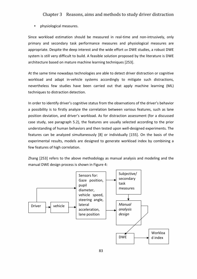
Chapter 3 Reasons, aims and methods to study driver distraction
83
• physiological measures.
Since workload estimation should be measured in real-time and non-intrusively, only
primary and secondary task performance measures and physiological measures are
appropriate. Despite the deep interest and the wide effort on DWE studies, a robust DWE
system is still very difficult to build. A feasible solution proposed by the literature is DWE
architecture based on mature machine learning techniques [253].
At the same time nowadays technologies are able to detect driver distraction or cognitive
workload and adapt in-vehicle systems accordingly to mitigate such distractions,
nevertheless few studies have been carried out that apply machine learning (ML)
techniques to distraction detection.
In order to identify driver’s cognitive status from the observations of the driver’s behavior
a possibility is to firstly analyze the correlation between various features, such as lane
position deviation, and driver’s workload. As for distraction assessment (for a discussed
case study, see paragraph 5.2), the features are usually selected according to the prior
understanding of human behaviors and then tested upon well-designed experiments. The
features can be analyzed simultaneously [8] or individually [155]. On the basis of the
experimental results, models are designed to generate workload index by combining a
few features of high correlation.
Zhang [253] refers to the above methodology as manual analysis and modeling and the
manual DWE design process is shown in Figure 4:
Driver vehicle
Sensors for:
Gaze position,
pupil
diameter,
vehicle speed,
steering angle,
lateral
acceleration, lane position
Subjective/
secondary
task measures
Manual
analysis
design
DWE Workload index
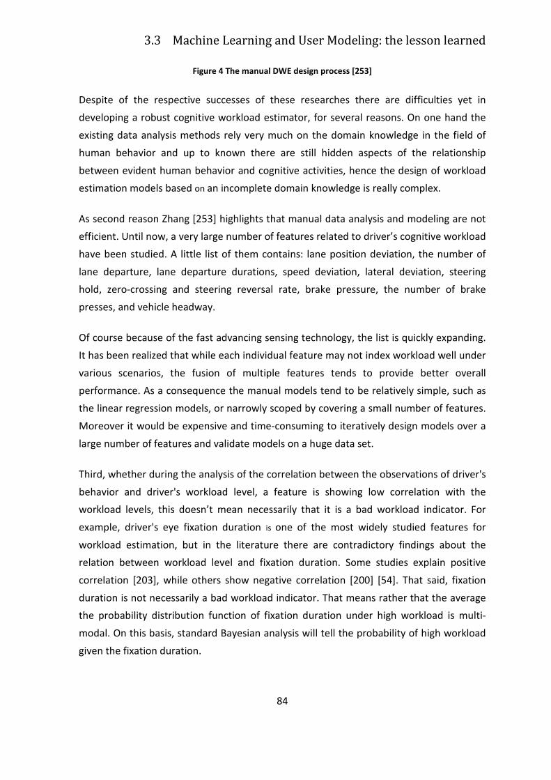
3.3 Machine Learning and User Modeling: the lesson learned
84
Figure 4 The manual DWE design process [253]
Despite of the respective successes of these researches there are difficulties yet in
developing a robust cognitive workload estimator, for several reasons. On one hand the
existing data analysis methods rely very much on the domain knowledge in the field of
human behavior and up to known there are still hidden aspects of the relationship
between evident human behavior and cognitive activities, hence the design of workload
estimation models based on an incomplete domain knowledge is really complex.
As second reason Zhang [253] highlights that manual data analysis and modeling are not
efficient. Until now, a very large number of features related to driver’s cognitive workload
have been studied. A little list of them contains: lane position deviation, the number of
lane departure, lane departure durations, speed deviation, lateral deviation, steering
hold, zero-crossing and steering reversal rate, brake pressure, the number of brake
presses, and vehicle headway.
Of course because of the fast advancing sensing technology, the list is quickly expanding.
It has been realized that while each individual feature may not index workload well under
various scenarios, the fusion of multiple features tends to provide better overall
performance. As a consequence the manual models tend to be relatively simple, such as
the linear regression models, or narrowly scoped by covering a small number of features.
Moreover it would be expensive and time-consuming to iteratively design models over a
large number of features and validate models on a huge data set.
Third, whether during the analysis of the correlation between the observations of driver's
behavior and driver's workload level, a feature is showing low correlation with the
workload levels, this doesn’t mean necessarily that it is a bad workload indicator. For
example, driver's eye fixation duration is one of the most widely studied features for
workload estimation, but in the literature there are contradictory findings about the
relation between workload level and fixation duration. Some studies explain positive
correlation [203], while others show negative correlation [200] [54]. That said, fixation
duration is not necessarily a bad workload indicator. That means rather that the average
the probability distribution function of fixation duration under high workload is multi-
modal. On this basis, standard Bayesian analysis will tell the probability of high workload
given the fixation duration.
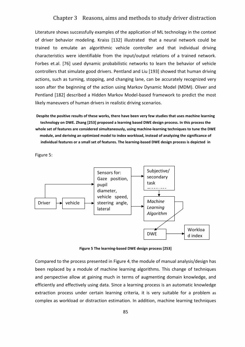
Chapter 3 Reasons, aims and methods to study driver distraction
85
Literature shows successfully examples of the application of ML technology in the context
of driver behavior modeling. Kraiss [132] illustrated that a neural network could be
trained to emulate an algorithmic vehicle controller and that individual driving
characteristics were identifiable from the input/output relations of a trained network.
Forbes et.al. [76] used dynamic probabilistic networks to learn the behavior of vehicle
controllers that simulate good drivers. Pentland and Liu [193] showed that human driving
actions, such as turning, stopping, and changing lane, can be accurately recognized very
soon after the beginning of the action using Markov Dynamic Model (MDM). Oliver and
Pentland [182] described a Hidden Markov Model-based framework to predict the most
likely maneuvers of human drivers in realistic driving scenarios.
Despite the positive results of these works, there have been very few studies that uses machine learning
technology on DWE. Zhang [253] proposed a learning based DWE design process. In this process the
whole set of features are considered simultaneously, using machine-learning techniques to tune the DWE
module, and deriving an optimized model to index workload, instead of analyzing the significance of
individual features or a small set of features. The learning-based DWE design process is depicted in
Figure 5:
Figure 5 The learning-based DWE design process [253]
Compared to the process presented in Figure 4, the module of manual analysis/design has
been replaced by a module of machine learning algorithms. This change of techniques
and perspective allow at gaining much in terms of augmenting domain knowledge, and
efficiently and effectively using data. Since a learning process is an automatic knowledge
extraction process under certain learning criteria, it is very suitable for a problem as
complex as workload or distraction estimation. In addition, machine learning techniques
Driver vehicle
Sensors for:
Gaze position,
pupil
diameter,
vehicle speed,
steering angle,
lateral
acceleration,
Subjective/
secondary
task
measures
Machine
Learning
Algorithm
DWE Workload index
3.3 Machine Learning and User Modeling: the lesson learned
86
are meant for analyzing huge amounts of data, discovering patterns, and extracting
relationships. Moreover, this change makes it possible for a DWE system to adapt to
individual drivers.
Other two interesting works on the use of ML techniques in the field of driver’s
distraction assessment are those of Liang and colleagues [147] and the ones of Kutila
[133] [134].
The main goal of Liang and colleagues [147] is to detect driver distraction exploring the
change of eye movements and driving performances, in order to accordingly adapt in-
vehicle systems. The results can be employed in real-time to detect driver’s cognitive
distraction, since they demonstrate that eye movements and simple measures of driving
performance can be used to detect driver distraction in real time.
The author applied Support Vector Machines (SVMs), which is a data mining method, to
develop a real-time approach for detecting cognitive distraction using drivers' eye
movements and driving performance data. During the empirical experiment, drivers were
asked to perform a secondary task while driving. Standard deviation of steering wheel
position, mean of steering error and standard deviation of lane position were collected as
driving measures. The data were used to train and test both SVM and logistic regression
models, and three different model characteristics were investigated: how distraction was
defined, which data were input to the model, and how the input data were summarized.
The Radial Basis Function (RBF) was selected as the kernel function for the SVM model
The results show that the SVM models were able to detect driver distraction with an
average accuracy of 81.1%, outperforming more traditional logistic regression models. In
particular, the authors pointed out that:
• SVM can fit linear and non-linear relationships, whereas logistic models can fit
only linear models
• SVM methods minimize the upper bound of generalization error during training,
whereas logistic models only minimize training errors. This makes SVM more
robust, since over-fitting is less probable than with logistic regression.
With the same training dataset, response bias of the SVM method can be adjusted to
increase performances by choosing parameter value before training, regardless of the
number of training instances in each class (“distraction”, “no-distraction”). While the
Chapter 3 Reasons, aims and methods to study driver distraction
87
response of logistic models largely depends on the ratio of training instances of the two
classes in the dataset, because logistic methods minimize training errors [233].
It is important to remark that the discrepancy between the experimental data and reality
recommend some prudence in generalizing the results. Furthermore, they used SVM with
RBF as Kernel function, but it could be also interesting to explore several kernels, or to
use different ML techniques, like HMM and ANN, in order to compare the results for the
same dataset [233].
Kutila and colleagues [133] [110] [134] [135] studied the feasibility of techniques and
methods for monitoring the driver’s momentary distraction. They used simultaneously
multiple signals: image processing and lane-keeping, measuring namely gaze, head and
lane related parameters. To address this aim, the authors’ adopted Support Vector
Machines (SVMs) as classifier, because they are able to generalize well and their
classification performance does not depend on the task or data at hand5. Moreover,
SVMs adapt nicely to nonlinear as well as multidimensional data [233].
Although Support Vector Machines are a promising approach for driver distraction
detection, other data mining/machine learning approaches may provide a
complementary or even potentially more effective method of detecting distraction.
During the first part of the SAVE-IT project, the use of Bayesian Network was investigated
to predict driver’s behaviour by utilising eye movement, but with a limited success.
The input parameters of the SAVE-IT classifier were eye movements and advanced eye
based measurements like saccades, fixation duration and blinking [233].
In a comparison between static BN (SBN) and dynamic BN (DBN) [146] the result was that
DBN models were more sensitive than SBN models, but there were no significant
differences in accuracy and response bias. Nevertheless, the DBNs, which model time-
dependent relationships between drivers’ behavior and cognitive state, produced the
most accurate and sensitive models, compared to SVM and SBN models. This indicates
that changes in drivers’ eye movements and driving performance along time are
important predictors of cognitive distraction. In the meanwhile, the SVM models detected
driver cognitive distraction more accurately than the SBN models. This implies that the
5 This is also the reason why they have been fairly successful in different kinds of tasks such as text
categorization, tumor classification, eye and pedestrian detection.
3.3 Machine Learning and User Modeling: the lesson learned
88
SVM learning technique has advantages over the BN technique. Both these approaches
(BN and SVM) aim at real-time detection, but there will still be an unavoidable lag from
when the driver’s cognitive state changes until the model recognizes such a change.
As general consideration, regardless of the chosen approach, it is important to remark
that, since the detection of cognitive distraction is a demanding procedure, it requires a
robust data fusion system. The real challenge is to integrate multiple data streams,
including eye movements and driving performance, in a logical manner to infer the
driver’s cognitive state. Data fusion systems can align data sets, correlate relative
variables, and combine the data to make detection or classification decisions [245].
Moreover data fusion can take place at different levels of abstraction. For instance,
sensor data are aggregated to measure driver performance at the most concrete level.
These performance measures can then be applied in the characterization of the driver
behavior at higher levels of abstraction, such as at the level of maneuvers. The fusion
systems can also constantly refine the estimates made at each level along time, allowing a
real-time estimation of cognitive distraction [233].
The empirical results of the use of ANFIS (Adaptive Neuro Fuzzy Inference Systems) and
NN (Neural Network) in modelling distraction will be presented in Chapter 5 (see
paragraph 5.2 for details).
89
Chapter 4
Integration of a driver behavior
model into a cognitive architecture
4.1 Cognitive architecture: research issues and
challenges in HCI.
This paragraph is aimed to understand which are the literature bases that may lead
toward an integration of a driver behavior model into a cognitive architecture, in order to
design effective preventive safety systems.
A preventive safety system is composed by three essential aspects:
1. adaptation
2. driver status assessment
3. maneuvers recognition
These three elements should be integrated into the cognitive architecture that stands
ADAS design up and in chapter 5 will be examined the empirical results about the
implementation of each of the three abovementioned aspects The positive feedback of
these results pave the way for the integration of these three aspects into a unique
cognitive architecture, that will be depicted in the conclusions of this thesis work.
4.2 Driver behavior model and cognitive architecture: a feasible
integration
90
Before getting the bottom of the matter, it will be considered what is a cognitive
architecture and why cognitive architecture is relevant for Human Computer Interaction
(HCI), considering also some of the past use of cognitive architectures in HCI research
The importance of the research on cognitive architectures is strictly related to the
achievement of a central goal of artificial intelligence and cognitive science: the creation
and understanding of synthetic agents that support the same capabilities as humans
[142]. This aim finds a practical and crucial application in the automotive domain and in
ADAS design.
As explained in the Adaptive Automation state of art (see paragraph 2.3.1.1), the new
frontiers of automotive research in preventive safety system is the developing of the
“horse”, that is a some sort of co-pilot able to assess the driving context, the driver’s
status and the undertaken maneuver, in order to detect a dangerous situation and
intervene in the driving task, assuring safety conditions. In this way the horse is a
“synthetic agents that support the same capabilities as humans”. Its cognitive
architecture “specifies the underlying infrastructure for an intelligent system” [142].
In few words, an architecture includes those aspects of a cognitive agent that are
constant over time and across different application domains. These usually include [142]:
1. the short-term and long-term memories that store content about the agent’s
beliefs, goals, and knowledge;
2. the representation of elements that are contained in these memories and their
organization into larger-scale mental structures;
3. the functional processes that operate on these structures, including the
performance mechanisms that utilize them and the learning mechanisms that
alter them.
Since the contents of an agent’s memories can change over time, Langlay [142] precise
that knowledge and beliefs are not considered to be part of that agent’s architecture.
They are just different programs running on the same computer architecture. In this way
different knowledge bases and beliefs can be interpreted by the same cognitive
architecture. The author propose a direct analogy with a building’s architecture: “which
consists of permanent features like its foundation, roof, and rooms, rather than its
furniture and appliances, which one can move or replace. As we will see, alternative
Chapter 4 Integration of a driver behavior model into a cognitive
architecture
91
cognitive architectures can differ in the specific assumptions they make about these
issues, just as distinct buildings differ in their layouts”.
In fact, Byrne [31] specifies that cognitive architecture is a broad theory of human
cognition based on a wide selection of human experimental data, and implemented as a
running computer simulation program, while Young [78][210] defines a cognitive
architecture as an embodiment of “a scientific hypothesis about those aspects of human
cognition that are relatively constant over time and relatively independent of task”6
A cognitive architecture alone cannot do anything, it has to be supplied with the
knowledge needed to perform a particular task. The combination of an architecture and a
particular set of knowledge is generally referred to as a model. In general, it is possible to
construct more than one model for any particular task. The specific knowledge
incorporated into a particular model is determined by the modeler.
Another centrally important feature of cognitive architectures is that model of a task
constructed in a cognitive architecture is runnable and produces a sequence of behaviors.
These behavior sequences can be compared with the sequences produced by human
users, also to help assess the quality of a particular model.
Another feature of many architectures is that they enable the creation of quantitative
models. Models based on cognitive architectures can produce in facts execution times,
error rates, and even learning curves. This is a major strength of cognitive architectures as
an approach to certain kinds of HCI problems.
Cognitive architectures are relevant to usability as an engineering discipline, have several
HCI-relevant applications in computing systems, and serve an important role in HCI as a
theoretical science, because, as stated above, computational models based on cognitive
architectures have the potential to provide detailed quantitative answers, and for more
than just execution times. Error rates, transfer of knowledge, learning rates, and other
6 Cognitive architectures differ from traditional research in psychology that include attention, memory,
problem solving, decision making, learning, and so on. Psychology follows a divide-and-conquer strategy
that tends to generate highly specific theories of a very limited range of phenomena. This limits the
usefulness of such theories for an applied domain like HCI where users employ a wide range of cognitive
capabilities in even simple tasks. Instead of asking “how can we describe this isolated phenomenon?”
people working on cognitive architectures can ask “how does this phenomenon fit in with what we already
know about other aspects of cognition?” [29].
4.2 Driver behavior model and cognitive architecture: a feasible
integration
92
kinds of performance measures are all metrics than can often be provided by
architecture-based models. Even if such models are not always precisely accurate in an
absolute sense, they may still be useful in a comparative sense [31] [30]. The author
proposes the following example: if a usability engineer is comparing interface A with
interface B and the model at his or her disposal does not accurately predict the absolute
times to complete some set of benchmark tasks, it may still accurately capture the
difference between the two interfaces, which may be more than enough.
Computational models can, in principle, act as surrogate users in usability testing, even
for special populations. For example, access to certain populations such astronauts, pilot
or an air traffic controller may be difficult or expensive, and bringing them in for repeated
usability tests may be not possible. Re-running a model to assess a change made for
example to the user interface should be easier than performing a new usability test for
each iteration of the system. With a quantitatively realistic model of the human in the
loop, this is possible, since execution times and error rates are reproducible. There is
another HCI-relevant application for high-fidelity cognitive models: populating of expert
users simulated worlds or situations, for example, in training an F-16 fighter pilot or in
video games [31].
Equally importantly, computational models have the capacity to be reactive in real time,
that is a crucial features for time-critical tasks.
In some ways, cognitive architectures constitute the antithesis of expert systems, which
provide skilled behavior in narrowly defined contexts [142].
Despite the multiple application of Cognitive Architecture, additional research is needed.
On one hand artificial intelligence and cognitive science have evolved, but fragmented
into a number of well-defined sub-disciplines, on the other hand commercial and
government applications increasingly require integrated systems that exhibit intelligent
behavior, not just improvements to the components of such systems [142]. It is the case
of automotive domain and ADAS application.
This demand can be met by an increased focus on architectures that support complex
cognitive behavior across a broad range of relevant tasks, that in the case of ADAS are
adaptation, driver status assessment, maneuver recognition.
Chapter 4 Integration of a driver behavior model into a cognitive
architecture
93
4.1.1 Example of Past Cognitive Architecture
The total history of cognitive architectures and HCI is too long to be adequately
described. In this paragraph some concrete examples reported in the literature will be
considered. Not all of them are as complete cognitive architectures, but they influenced
their development and use in HCI.
4.1.1.1 The Model Human Processor (MHP)
The Model Human Processor (MHP) and GOMS derives from the psychology of Human-
Computer Interaction: they are not running cognitive architectures, but they share the
same intention and as a consequence they influence the development of current
cognitive architectures [31].
The MHP represents a synthesis of the literature on cognitive psychology and human
performance and sketches the framework around which a cognitive architecture could be
implemented [31]. In this system, there are three processors: one cognitive, one
perceptual, and one motor. In some cases the system behaves essentially serially (see
Figure 6). For instance, in order for the system to press a key in response to the
appearance of a light, the perceptual processor must detect the appearance of the light
and transmit this information to the cognitive processor. The cognitive processor’s job is
to decide what the appropriate response should be, and then transmit that to the motor
processor, which is responsible for actually executing the appropriate motor command. In
this situation, the processors act serially, one after another. However, in more complex
tasks such as transcription typing, all three processors will often be working in parallel
[45].
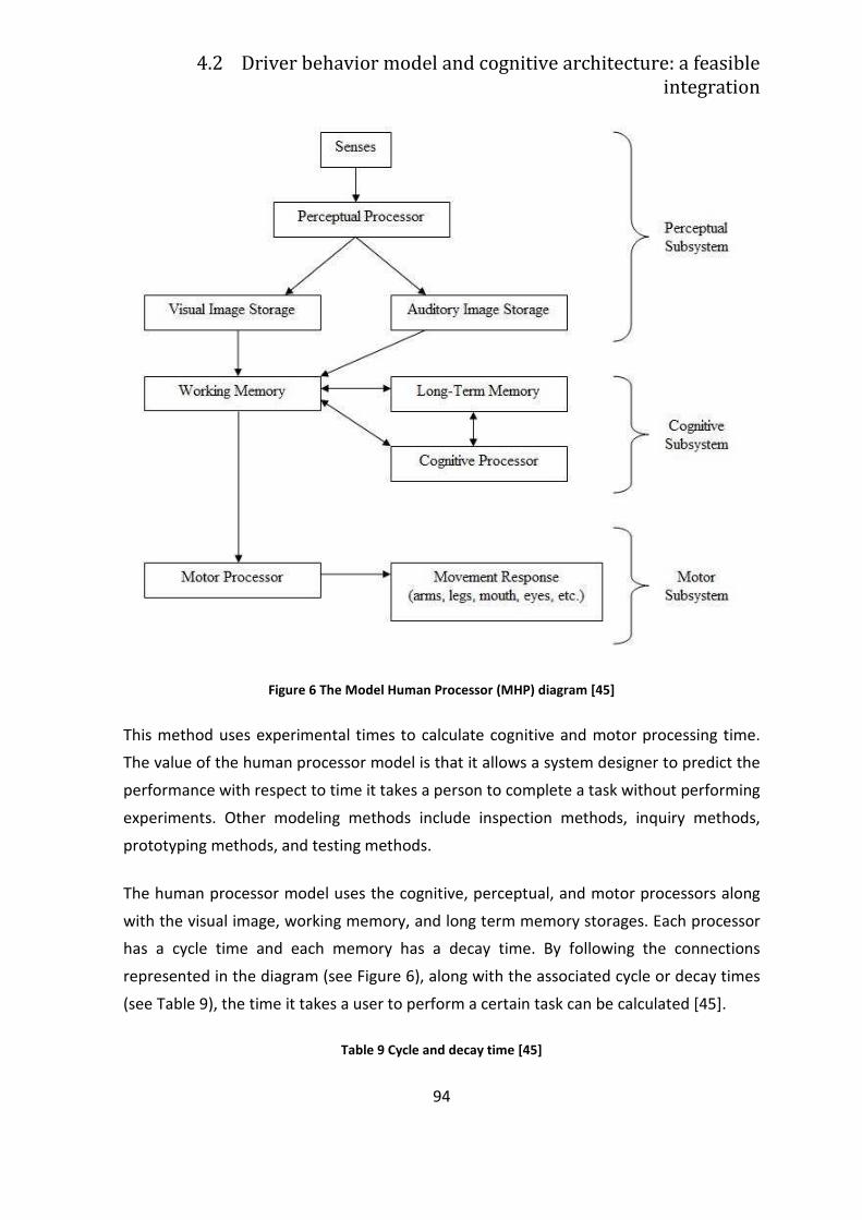
4.2 Driver behavior model and cognitive architecture: a feasible
integration
94
Figure 6 The Model Human Processor (MHP) diagram [45]
This method uses experimental times to calculate cognitive and motor processing time.
The value of the human processor model is that it allows a system designer to predict the
performance with respect to time it takes a person to complete a task without performing
experiments. Other modeling methods include inspection methods, inquiry methods,
prototyping methods, and testing methods.
The human processor model uses the cognitive, perceptual, and motor processors along
with the visual image, working memory, and long term memory storages. Each processor
has a cycle time and each memory has a decay time. By following the connections
represented in the diagram (see Figure 6), along with the associated cycle or decay times
(see Table 9), the time it takes a user to perform a certain task can be calculated [45].
Table 9 Cycle and decay time [45]
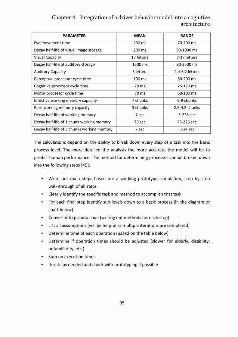
Chapter 4 Integration of a driver behavior model into a cognitive
architecture
95
PARAMETER MEAN RANGE
Eye movement time 230 ms 70-700 ms
Decay half-life of visual image storage 200 ms 90-1000 ms
Visual Capacity 17 letters 7-17 letters
Decay half-life of auditory storage 1500 ms 90-3500 ms
Auditory Capacity 5 letters 4.4-6.2 letters
Perceptual processor cycle time 100 ms 50-200 ms
Cognitive processor cycle time 70 ms 25-170 ms
Motor processor cycle time 70 ms 30-100 ms
Effective working memory capacity 7 chunks 5-9 chunks
Pure working memory capacity 3 chunks 2.5-4.2 chunks
Decay half-life of working memory 7 sec 5-226 sec
Decay half-life of 1 chunk working memory 73 sec 73-226 sec
Decay half-life of 3 chunks working memory 7 sec 5-34 sec
The calculations depend on the ability to break down every step of a task into the basic
process level. The more detailed the analysis the more accurate the model will be to
predict human performance. The method for determining processes can be broken down
into the following steps [45].
• Write out main steps based on: a working prototype, simulation, step by step
walk-through of all steps
• Clearly identify the specific task and method to accomplish that task
• For each final step identify sub-levels down to a basic process (in the diagram or
chart below)
• Convert into pseudo code (writing out methods for each step)
• List all assumptions (will be helpful as multiple iterations are completed)
• Determine time of each operation (based on the table below)
• Determine if operation times should be adjusted (slower for elderly, disability,
unfamiliarity, etc.)
• Sum up execution times
• Iterate as needed and check with prototyping if possible
4.2 Driver behavior model and cognitive architecture: a feasible
integration
96
4.1.2 GOMS (goals, operators, methods, and selection
rules)
Another concept that has been highly influential throughout HCI and computational
modelers: this is GOMS, which stands for goals, operators, methods, and selection rules.
GOMS is a framework for task analysis that describes routine cognitive skills in terms of
the listed four components. Routine cognitive skills are those where the user knows what
the task is and how to do the task without doing any problem solving (i.e . text editing
with a familiar editor) [45] [31].
A GOMS analysis of a task describes the hierarchical procedural knowledge a person must
have to successfully complete that task. Based on that, and the sequence of operators
that must be executed, it is possible to make quantitative predictions about the execution
time for a particular task. Other analyses, such as predictions of error, functionality
coverage, and learning time are also sometimes possible. The core point and the relation
to cognitive architectures is that GOMS analysis is originally based on a production rule
(IF-THEN condition-action pairs) analysis [31].
This representation typically consists of a set of loosely-structured data elements such as
propositions or attribute-value pairs. This set is called the “working memory” or
“declarative memory.” The actions may be high-level (e.g., “turn left”) or the can modify
the contents of declarative memory, which usually means that a different production or
productions will match on the next cycle [31]. At this abstract and symbolic level,
production systems are Turing complete and thus can compute anything that is
computable [176], thus, they should be flexible enough to model the wide array of
computations performed by the human cognitive system.
This is relevant to cognitive architectures because most cognitive architectures are (or
contain) production systems. GOMS was actually abstracted from production rule
analysis. Moreover for routine cognitive skills, the structure of the productions was quite
similar across tasks and a more abstract representation was possible[45]. Therefore,
translating a GOMS analysis into production rules, the language of most cognitive
architectures, is usually straightforward. Vice versa it is quite simple to derive a GOMS
Chapter 4 Integration of a driver behavior model into a cognitive
architecture
97
analysis from the set of productions used to model the task and influenced the evolution
of research on cognitive architecture and HCI [31]
4.1.3 Cognitive Complexity Theory (CCT)
Cognitive complexity theory [30][29] is a psychological theory of transfer of training
applied to HCI. That is, how much is the knowledge gained from using the old interface
“transferred” to using the new interface?
The major points of CCT are:
• Knowledge of the procedures that people need to execute to perform routine
tasks can be represented with production rules. The relevant production rules can
be generated based on a GOMS analysis of the task to be modeled.
• The complexity of a task will be reflected in the number and content of the
production rules. When certain conventions are adopted about the style of those
production rules, complexity is reflected almost entirely in the number of rules.
• The time it takes to execute a procedure can be predicted with a production
system that interprets those rules along with a set of typical operator times.
• The time it takes to learn a task is a function of the number of new rules that the
user must learn.
• Some predictions about errors and speedup with practice can also be gleaned
from the contents of the production rules.
The necessary knowledge, and thus the production rules for representing it, are a
function both of the task from the user point of view and the interface provided to
accomplish the task. It should be noticed that CCT models, like a GOMS analysis, exclude
to model many details of user behavior. For example anything that falls outside the
domain of procedural knowledge (how-to-do-it knowledge). CCT models also do not
include any model of the perceptual processes required by users. In spite of these
limitations numerous laboratory experiments provide empirical support for many of the
claims of CCT [30][29].
4.2 Driver behavior model and cognitive architecture: a feasible
integration
98
4.1.3.1 CAPS
CAPS (collaborative activation-based production system) is a cognitive architecture
designed to model individual differences in working memory (WM) capacity and the
effects of working memory load.
Like most other production systems, CAPS contains two kinds of knowledge, declarative
memory and productions. Declarative memory elements in CAPS also have associated
with them an activation value, and elements below a threshold level of activation cannot
be matched by productions’ IF sides. Additionally, unlike most other production systems,
the THEN side of a CAPS production may request that the activation of an element be
incremented. For this to be truly useful in modeling working memory, there is a limit to
the total amount of activation available across all elements. If the total activation exceeds
this limit, then all elements lose some activation to bring the total back within the limit.
This provides a mechanism for simulating human working memory limitations [31].
4.1.4 Example of Current Cognitive Architecture
There are currently cognitive architectures that are being actively developed, updated,
and applied to HCI-oriented tasks. Three of the four most prominent are production
systems, or rather are centrally built around production systems. They are Soar, EPIC, and
ACT-R (particularly ACT-R/PM). While all contain production rules, the level of granularity
of an individual production rule varies considerably from architecture to architecture. All
of them have been influenced by the MHP.
4.1.4.1 LICAI/CoLiDeS
Previous cognitive architecture assumes that the users being modeled are relatively
skilled with the specific interface being used: in fact a poor job of modeling relatively raw
novices has been done. One of the main goals of LICAI [126] is instead addressing this
concern. The paradigm question addressed by LICAI is “how do users explore a new
interface?” [31].
Chapter 4 Integration of a driver behavior model into a cognitive
architecture
99
LICAI is a good example of a non-production system architecture and has been used in an
HCI context. Unlike the other architectures discussed, LICAI’s central control mechanisms
are not based on a production system. Instead, LICAI is built around an architecture
originally designed to model human discourse comprehension, construction-integration
(C-I) [123]. Like production systems, C-I’s operation is cyclic. Nevertheless, what happens
on those cycles is somewhat different than what happens in a production system [31].
Each cycle is divided into two phases, construction and integration. In the construction
phase, an initial input is fed into a weakly-constrained rule-based process which
generates a network of propositions. Items in the network are linked on the basis of their
argument overlap. In the following integration phase, activation propagates through the
network in a neural network-like fashion. Fundamentally, this phase is a constraint-
satisfaction phase, which is used to select one of the propositions in the network as the
“preferred” one. Action representations will be added to the network during the
construction phase, and an action will be selected during the integration phase. The
action will be performed, and the next cycle initiated. Various C-I models have used this
basic process to select things other than actions. The original CI system used these cycles
to select between different interpretations of sentences [31].
There are three main kinds of cycles in LICAI: one type selects actions, one generates
goals, and one selects goals. This is in contrast to how most HCI tasks have been modeled
in production system architectures; in such systems, the goals are usually included in the
knowledge given to the system. LICAI is an excellent mean for capturing many of the
empirical regularities in exploratory learning of a GUI interface. This is an important issue
for many interfaces, particularly any interface that is aimed at a walk-up-and-use
audience (i.e. ATM) [31].
In recent times, LICAI has been updated and renamed to CoLiDeS (Comprehension based
Linked model of Deliberate Search) [127]with a more robust attentional mechanism and a
much more sophisticated notion of semantic similarity based on Latent Semantic Analysis
(LSA) [136].
4.2 Driver behavior model and cognitive architecture: a feasible
integration
100
4.1.4.2 Soar
The development of Soar is generally credited to Allan Newell [176] and Soar has been
used to model a wide variety of human cognitive activity from syllogistic reasoning [196]
to flying combat aircraft in simulated wargames [113]. Soar was Newell’s candidate
“unified theory of cognition” and was the first computational theory to be offered as
such.
The guiding principle behind the design of Soar is the Problem Space Principle (from the
Model Human Processor). Soar casts all cognitive activity as occurring in a problem space,
which consists of a number of states. States are transformed through the application of
operators. Also Soar’s operation is cyclic, but the central cycle in Soar’s operation is called
“decision cycle”. Basically, on each decision cycle, Soar answers the question “what do I
do next?” Soar does this in two phases. First, all productions that match the current
contents of declarative memory fire. This usually causes changes in declarative memory,
so other productions may now match. Those productions are allowed to fire, and this
continues until no new productions fire. At this time, the decision procedure gets
executed, in which Soar examines a special kind of declarative memory element, the
preference. Preferences are statements about possible actions, Soar examines the
available preferences and selects an action. Thus, each decision cycle may contain many
production cycles [31].
Other than the ubiquitous application of the problem space principle, Soar’s most
defining characteristics come from two mechanisms developed specifically in Soar,
universal subgoaling and a general-purpose learning mechanism [31].
In this decision process there is no guarantee to have an unambiguous set of preferences
to work with. If the decision procedure is unable to select an action, an impasse occurs.
Rather than halting or entering a failure state, Soar sets up a new state in a new problem
space with the goal of resolving the impasse. In the course of resolving one impasse, Soar
may encounter another impasse and create another new problem space, a nd so on. As
long as the system is provided with some fairly generic knowledge about resolving
degenerate cases (e.g. if all else fails, the choose is random), this universal subgoaling
allows Soar to continue even in cases where there is little knowledge. Learning in Soar is a
Chapter 4 Integration of a driver behavior model into a cognitive
architecture
101
by-product of universal subgoaling. Whenever an impasse is resolved, Soar creates a new
production rule [31].
Soar has also been used to implement models of exploratory learning. In particular, Soar
is more focussed on learning than any of the other systems, and learnability is clearly an
important property for many user interfaces. Second, it is known that Soar models scale
up to very complex tasks, that have not been modeled in other architectures [31].
4.1.4.3 EPIC
Models discussed up to know have been almost purely cognitive models. That is, the
perception and action parts of the models have been handled in an indirect, abstract way.
These models focus only on the cognition involved, even if the original formulation of the
MHP included processors for perception and motor control. And, in fact, user interfaces
have also moved from having almost exclusively cognitive demands to relying much more
heavily on perceptual-motor capabilities. This is one of the hallmarks of the GUI, the shift
to visual processing and direct manipulation rather than reliance on complex composition
of commands.
EPIC was instead explicitly designed to pair high-fidelity models of perception and motor
mechanisms with a production system. Constructing a model in EPIC thus requires
specification of both the knowledge needed in the form of production rules as well as
some relevant perceptual-motor parameters. There are several processors and two types
of parameters in EPIC: standard, which are system parameters believed to be fixed across
all tasks, and typical, which are free to vary across task situations, but have more-or less
conventional values. All the processors in EPIC run in parallel with one another. More
specifically, what is modeled in each of the processors is primarily time course [31].
On the motor side, EPIC each movement includes a preparation phase and an execution
phase. The time to prepare a movement is dependent on the number of movement
features that must be prepared for each movement and the features of the last
movement prepared. Features that have been prepared for the previous movement can
sometimes be re-used, saving time. EPIC can make repeated identical movements rapidly
because there is no feature preparation time necessary if the movements are identical. If
they are not identical, the amount of savings is a function of how different the current
4.2 Driver behavior model and cognitive architecture: a feasible
integration
102
movement is from the previous one. The execution time for a movement corresponds
roughly to the time it physically takes to execute the movement [31].
EPIC’s Cognitive Processor is a production system, the same one that was used for the
earlier CCT work. One highly salient feature of this system is that multiple rules are
allowed to fire on a production cycle. Productions in this system are at a much higher
grain size than productions in Soar, which gives EPIC a highly parallel quality at all levels.
That is, all the processors work in parallel and EPIC’s cognitive processor is itself capable
of parallel processing. As a consequence EPIC is particularly effective in multiple-task
situations. But as for human beings, many of the perceptual-motor processors are
effectively serial [31].
It is interesting to remark that multiple-task issues have been poorly modeled before
EPIC. One of the first major applications of EPIC was to a deceptively simple dual-task
paradigm known as the psychological refractory period (PRP) [159]: in this task,
laboratory subjects are typically confronted with two choice reaction time tasks. What
the EPIC models of these experiments show is that people’s low-level strategies for
scheduling the tasks play a large role in determining performance in this simple paradigm
[31].
EPIC has also been used to model some of the classic psychological results from the short-
term memory literature [121]. This concerns the question of how much people can
remember when they repeat a string of words (or numbers) to themselves. EPIC has been
the first serious quantitative model of this process (called “articulatory rehearsal” in the
psychology literature). An accurate model of this process is clearly important in HCI
applications, as many interfaces force people to remember many things over short
periods and rehearsal is a likely response to that demand.
EPIC has been used to model several tasks relevant for HCI: menu selection, telephone
assistance operators (TAOs). While LICAI and Soar have not been adequately equipped to
deal more refined perception and action components, EPIC does not include any learning
mechanisms. Like other production system models, EPIC provides a certain amount of
freedom to the modeler in model construction and the production rule model may be
derived from another structured representation such as a GOMS model [31].
Chapter 4 Integration of a driver behavior model into a cognitive
architecture
103
4.1.4.4 ACT-R
ACT-R 6 [6] is organized into a set of modules, each of which processes a different type of
information. These include [142]:
• sensory modules for visual processing
• motor modules for action
• an intentional module for goals
• a declarative module for long-term declarative knowledge.
Each module has an associated buffer that holds a relational declarative structure
(chunk). ACT-R’s short-term memory consist of the whole set of these buffers. The
production rules included in the long-term memory coordinate the processing of the
modules. The conditions of each production test chunks in the short-term buffers, while
its actions modify the buffers upon application. Some changes transform existing
structures, while others initiate actions in the associated modules, such as executing a
motor command or retrieving a chunk from long-term declarative memory. Each
declarative chunk has an associated base activation that reflects its past usage and
influences its retrieval from long-term memory, while each production has an expected
cost (in terms of time needed to achieve goals) and probability of success [142].
On every cycle, ACT decides which productions match against the contents of short-term
memory. This retrieval process is influenced by the base activation for each chunk it
matches. ACT computes the utility for each matched production as the difference
between its expected benefit (the desirability of its goal times its probability of success)
and its expected cost. The system selects the production with the highest utility (after
adding noise to this score) and executes its actions. The new situation leads new
productions to match and fire, so that the cycle continues. Learning occurs in ACT-R at
both structural and statistical levels .
ACT-R has played a central role in tutoring systems [130], and it has also been used to
control mobile robots that interact with humans [240].
4.2 Driver behavior model and cognitive architecture: a feasible
integration
104
4.1.4.5 Icarus
Icarus is a more recent architecture [141] based on two distinct forms of knowledge:
• Concepts describe classes of environmental situations in terms of other concepts
• Skills specify how to realize goals by decomposing them into ordered sub-goals.
Both concepts and skills involve relations among objects, and both require a hierarchical
organization on long-term memory, starting from perceptions until executable actions.
Basically Icarus interpreter works on a recognize-act cycle. Time by time, the architecture
places descriptions of noticeable objects into a perceptual buffer. The system compares
primitive concepts to these percepts and adds matched instances to short-term memory
as beliefs. These in turn trigger matches of higher-level concepts, with the process
continuing until Icarus infers all deductively implied beliefs. Next, starting from a top-level
goal, it finds a descending path through the skill hierarchy in which each sub-skill has
satisfied conditions. When a path finishes in a primitive skill with executable actions, the
architecture applies these actions to affect the environment. This leads to new percepts,
changes in beliefs, and reactive implementation of additional skill paths to achieve the
agent’s goals.
If Icarus finds a non applicable path through the skill hierarchy that is relevant to a top-
level goal, it turns to a problem solving strategy, using a variant of means-ends analysis.
When the problem solver achieves a goal, Icarus creates a new skill indexed by that goal
and with one or more ordered sub-goals that are based on the problem solution, to be
used whether the system may encounter similar problems in the future [140].
Researchers use Icarus to develop agents for domains that encompass a combination of
inference, execution, problem solving, and learning as logistics planning, controlling
synthetic characters in simulated virtual environments, including ones that involve urban
driving [139] and first person shooter scenarios [39]. Up to now there is an effort to link
Icarus to physical robots that carry out joint activities with humans.
105
4.2 Driver behavior model and cognitive
architecture: a feasible integration
As stated in the introduction of this chapter, a preventive safety systems is composed by
three essential aspects, adaptation, driver status assessment, maneuvers recognition,
that can be defined as lower-level control behaviors. Driver status assessment and
maneuvers recognition can be considered as lower-level models of control, while
adaptation strategies are a higher-level model of cognitive processing and decision
making.
What should be done is to effectively combine the lower-level models of control with the
higher-level model of cognitive processing and decision making. The higher-level cognitive
components of such an integrated driver model are responsible for maintaining situation
awareness, determining strategies for navigation, deciding when to initiate and terminate
maneuvers, and managing other tasks that are not immediately relevant to the primary
driving task (e.g. filtering the incoming phone calls) [214].
An integrated driver model needs task prioritization and attention management to handle
the multitasking nature of the driving task [34]. The challenge is to find the best suited
computational framework for tying together existing lower-level control models with
higher-level goal setting, maintaining the parameters and constraints of cognition (e.g.,
memory and forgetting effects, errors, attention allocation) and of visual-motor
performance (e.g., manual control actions, eye movements).
Considering that a cognitive architecture is a theory of human cognition and perceptual-
motor actions that provides a rigorous framework for building, running, and testing
computational models of behavior, they are suitable for the developing of a driver
integrated model. By developing a model of driving in a cognitive architecture, the model
inherits all the cognitive and perceptual-motor predictions of the architecture and allows
for more psychologically plausible models of behavior. The model also produces
quantitative predictions about control and perceptual behavior that can be compared
directly to observed driver behavior (e.g., steering and eye-movement data).
Consequently, the model provides a theoretical understanding of driving behavior, a
4.2 Driver behavior model and cognitive architecture: a feasible
integration
106
practical formalization of driver intentions for intelligent vehicle support systems, or a
test-bed to predict the effect of various in-car systems on driver behavior [214].
As it has been explained in previous paragraphs, cognitive architectures generally rely on
a central cognitive processor to maintain a mental model and make decisions about
higher-level strategies to execute. This processor communicates with numerous
perceptual and motor processors that run in parallel with the cognitive processor,
executing requested commands from cognition and communicating sensory input to
cognition [214].
Any model developed in a cognitive architecture should tie both cognitive and
perceptual-motor aspects of behavior. As a consequence, this feature really facilitates the
integration of lower-level control models, such as for lateral or longitudinal control, with
higher-level decision making models that act upon the current situation and the current
needs and desires of the driver, such as and adaptation strategy that acts as an horse.
Cognitive architectures allow to implement this conceptual model as a computational
predictive model.
The other important benefit of cognitive architectures is the possibility to model common
psychophysical phenomena. For instance, cognitive architectures typically have a
mechanism for modeling how people store, recall, and sometimes forget information;
how people execute manual motor control for typing and other tasks; and how people
move their eyes to visual targets and encode the perceived information [214]. This is of
paramount importance for the driving distraction assessment, since
Thanks to cognitive architecture it is possible to develop behavioral models for complex
domains, such as driving. Salvucci and colleagues [214]notice that several of the most
important phenomena successfully modeled by cognitive architectures might be
addressed in driving:
• individual variability: Architectures allow for several types of variability ranging
from simple errors to statistical variations in higher-level cognitive strategies. The
parameters involved in such variability could be tuned in driver models to
represent different classes or types of drivers (e.g., younger versus older, passive
versus aggressive).
Chapter 4 Integration of a driver behavior model into a cognitive
architecture
107
• satisfying behavior: Most part of architectures do not guarantee optimal
performance, but rather perform to a "satisfying" threshold above which any
performance is acceptable, as occurs in real driver behavior, that is often
satisfying rather than optimal [33] [34]
• attention and attentional capacity: The amount of information drivers can
process through visual attention is much more limited than the huge quantity of
things and events that are present in their field of view. Moreover to process such
information they requires movement of attention between salient regions of the
view. Architectures help to describe how much information can be processed,
how quickly it is processed, and how this processing may interfere with other
driving tasks.
• working memory load: Architectures typically include limits on the amount of
information that can be mentally stored and processed during a given time period.
Such limits help to describe and analyze cognitive limitations in dealing with heavy
multitasking with multiple tasks or instruments (e.g., a cell phone or navigation
device).
• seriality versus parallelism: The necessity of multitasking during driving focuses
on the important issue of how much processing (visual, motor, and cognitive) can
be done in parallel and how much must be done serially. Architectures with
limited parallelism and primarily sequential execution is best suited to account for
human behavior, constraining in this way the structure of driver models and
capturing certain aspects of driver limitations.
• workload: Generally speaking, architectures have some interpretation of
multitasking workload for their particular parameters and constraints, allowing a
given driver model to predict effects on mental and physical workload on the basis
of different settings of these parameters for different individuals and situations.
Salvucci and colleagues [214] precise also that that the above aspects of behavior may be
relatively interdependent, as a conseuence another advantage of a cognitive architecture
is that it allows for rigorous exploration of the interactions between any combination of
these factors.
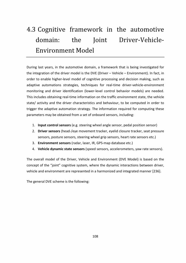
108
4.3 Cognitive framework in the automotive
domain: the Joint Driver-Vehicle-
Environment Model
During last years, in the automotive domain, a framework that is being investigated for
the integration of the driver model is the DVE (Driver – Vehicle – Environment). In fact, in
order to enable higher-level model of cognitive processing and decision making, such as
adaptive automations strategies, techniques for real-time driver-vehicle-environment
monitoring and driver identification (lower-level control behavior models) are needed.
This includes obtaining real-time information on the traffic environment state, the vehicle
state/ activity and the driver characteristics and behaviour, to be computed in order to
trigger the adaptive automation strategy. The information required for computing these
parameters may be obtained from a set of onboard sensors, including:
1. Input control sensors (e.g. steering wheel angle sensor, pedal position sensor)
2. Driver sensors (head-/eye movement tracker, eyelid closure tracker, seat pressure
sensors, posture sensors, steering wheel grip sensors, heart rate sensors etc.)
3. Environment sensors (radar, laser, IR, GPS-map database etc.)
4. Vehicle dynamic state sensors (speed sensors, accelerometers, yaw rate sensors).
The overall model of the Driver, Vehicle and Environment (DVE Model) is based on the
concept of the “joint” cognitive system, where the dynamic interactions between driver,
vehicle and environment are represented in a harmonized and integrated manner [236].
The general DVE scheme is the following:
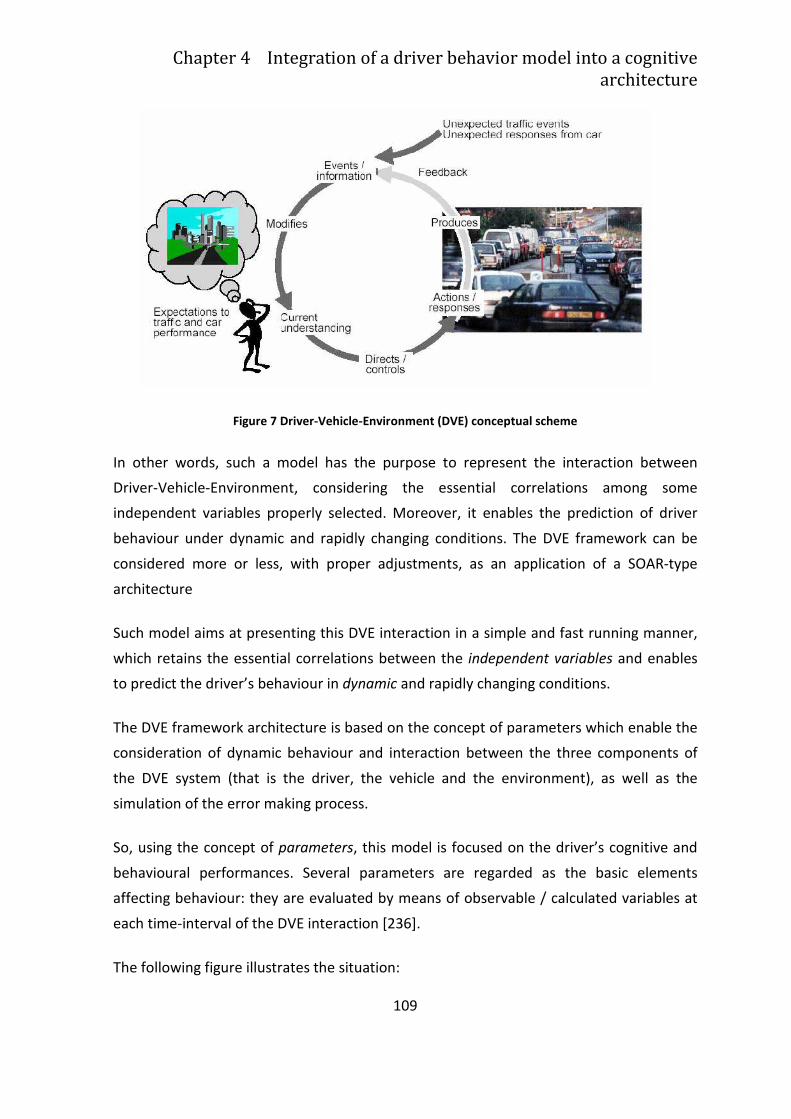
Chapter 4 Integration of a driver behavior model into a cognitive
architecture
109
Figure 7 Driver-Vehicle-Environment (DVE) conceptual scheme
In other words, such a model has the purpose to represent the interaction between
Driver-Vehicle-Environment, considering the essential correlations among some
independent variables properly selected. Moreover, it enables the prediction of driver
behaviour under dynamic and rapidly changing conditions. The DVE framework can be
considered more or less, with proper adjustments, as an application of a SOAR-type
architecture
Such model aims at presenting this DVE interaction in a simple and fast running manner,
which retains the essential correlations between the independent variables and enables
to predict the driver’s behaviour in dynamic and rapidly changing conditions.
The DVE framework architecture is based on the concept of parameters which enable the
consideration of dynamic behaviour and interaction between the three components of
the DVE system (that is the driver, the vehicle and the environment), as well as the
simulation of the error making process.
So, using the concept of parameters, this model is focused on the driver’s cognitive and
behavioural performances. Several parameters are regarded as the basic elements
affecting behaviour: they are evaluated by means of observable / calculated variables at
each time-interval of the DVE interaction [236].
The following figure illustrates the situation:
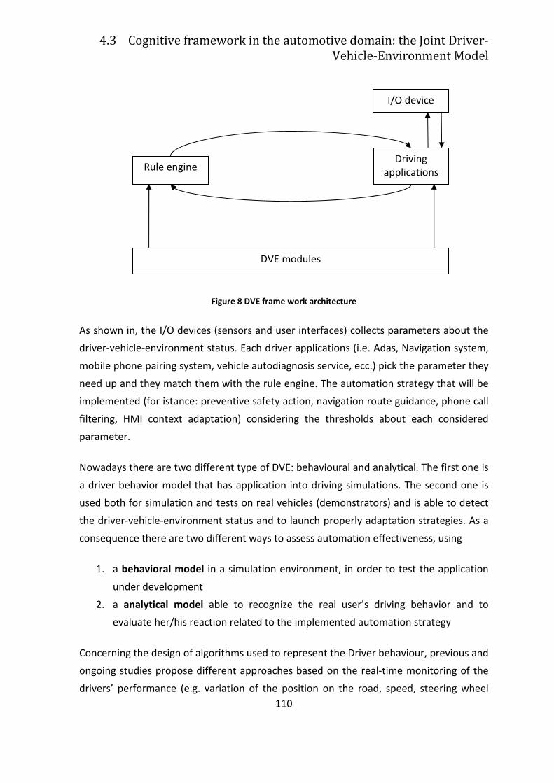
4.3 Cognitive framework in the automotive domain: the Joint Driver-
Vehicle-Environment Model
110
Figure 8 DVE frame work architecture
As shown in, the I/O devices (sensors and user interfaces) collects parameters about the
driver-vehicle-environment status. Each driver applications (i.e. Adas, Navigation system,
mobile phone pairing system, vehicle autodiagnosis service, ecc.) pick the parameter they
need up and they match them with the rule engine. The automation strategy that will be
implemented (for istance: preventive safety action, navigation route guidance, phone call
filtering, HMI context adaptation) considering the thresholds about each considered
parameter.
Nowadays there are two different type of DVE: behavioural and analytical. The first one is
a driver behavior model that has application into driving simulations. The second one is
used both for simulation and tests on real vehicles (demonstrators) and is able to detect
the driver-vehicle-environment status and to launch properly adaptation strategies. As a
consequence there are two different ways to assess automation effectiveness, using
1. a behavioral model in a simulation environment, in order to test the application
under development
2. a analytical model able to recognize the real user’s driving behavior and to
evaluate her/his reaction related to the implemented automation strategy
Concerning the design of algorithms used to represent the Driver behaviour, previous and
ongoing studies propose different approaches based on the real-time monitoring of the
drivers’ performance (e.g. variation of the position on the road, speed, steering wheel
I/O device
Driving applications
DVE modules
Rule engine
Chapter 4 Integration of a driver behavior model into a cognitive
architecture
111
movements) or the drivers’ physiological status performing primary and secondary tasks
(e.g. eye gaze, eye movements, heart frequency variation, galvanic skin response, etc.).
Basing on these information, these approaches allow to predict specific drivers’ profiles
(e.g. stressed, aggressive, tired, distracted, high workload etc.) and are developed
following machine learning approaches. Thanks to machine learning, information on
drivers’ profile can be automatically extracted from data, by computational and statistical
methods applied to observable information (e.g. drivers’ performance data).
In the case of the driver , the high level parameters contained in the DVE module are [41]:
• Experience/competence (EXP): the accumulation of knowledge or skills that result
from direct participation in the driving activity;
• Attitudes/personality (ATT): a complex mental state involving beliefs, feelings and
dispositions to act in certain ways;
• Task Demand (TD): the demands of the process of achieving a specific and
measurable goal using a prescribed method;
• Driver State (DS): Driver physical and mental ability to drive (fatigue, sleepiness…);
• Situation Awareness/Alertness (SA): perception of the elements in the
environment within a volume of time and space, the comprehension of their
meaning and the projection of their status in the near future.
A subset of this parameters are a priori defined, following literature indications. The other
ones are computed on-line.
On such premises, an experiment has been carried out at the driving simulator of the
University of Modena and Reggio Emilia [236] (the detailed discussion will be presented in
paragraph 5.2). The parameter on-line computed is Task Demand (TD). The main
objective of the tests , was to collect data from real-drivers in order to analyse the
driver’s behaviour and, based on this, the possible variation of specific driver model
parameters and related variables.
These parameters were modeled through Fuzzy relationships [231]: the tuning and
validation of these relationships was carried out following an ANFIS (Adaptive Neuro-
Fuzzy Inference System) and a Neural Network approach.
4.3 Cognitive framework in the automotive domain: the Joint Driver-
Vehicle-Environment Model
112
ANFIS is a fuzzy inference system (FIS) in the framework of adaptive networks [114],
hance ANFIS can be considered as a basis for constructing a set of fuzzy “if-then” rules
with appropriate membership functions (functions representing the degree of thruth as
an extention of evaluation), in order to generate the stipulated pairs of inputs/outputs
and to take into account the human knowledge, by using a hybrid learning procedure.
An Artificial Neural Networks (ANN) system is an information processing paradigm
inspired by the human brain and it consists in a large number of highly interconnected
processing elements, working together to cope with specific problems (for details, see
[92]. With regard to the biological inspiration, the brain consists of a large number
(approximately 1011) of highly connected elements (approximately 104 connections per
element) called neurons [236].
Although ANN is very far from approaching the complexity of human brain there are two
key similarities between biological and artificial neural networks [236].
1 The building blocks of both networks are computational devices (although artificial
neurons are much simpler than biological neurons) highly interconnected.
2 The connections between neurons determine the function of the network.
Hence ANN are non-linear information processing devices, built from interconnected
elementary processing units, called neurons (which make the processing task). The signals
are transmitted by connection links, possessing an associated weight, which is multiplied
along with the incoming signal (the input of the net) for any typical neural net. So the
output signal is obtained by applying activations to the net input [236].
Summing up, it is possible to say that an ANN is characterised by:
1 An architecture (connection between neurons)
2 Training or learning (determining weights on the connections)
3 Activation function
The goal of the driving experiment was to provide reliable data for driver’s model
parameters learning and validation.
According to a literature analysis [236] ANFIS and Neural Network approaches have been
chosen for modeling the cognitive aspects of a driver, as it is requested in the DVE
Chapter 4 Integration of a driver behavior model into a cognitive
architecture
113
framework. Moreover, it has been taken into consideration that the final goal is to get an
online method of parameters estimation, directly on-board vehicle. Usually in literature,
indicators describing drivers’ behavior and cognitive status are post-processed for
research and analysis purposes, e.g. to evaluate drivers’ behavioral/cognitive change due
to the variation of environmental conditions or drivers’ status. Here, the aim was the
development of DVE model parameters called Task Demand and Distraction (i.e. a
component of the Driver Status parameter) able to infer the increase of drivers’ cognitive
impairment and visual attention allocation on the basis of drivers’ behavioral data
available on the vehicle network.
In this research, ANFIS and Neural-Network Toolboxes of MATLAB, (www.matworks.com)
has been used, since it provides quite simple tools to manage the implementation of an
ANFIS and NN applications. In fact, the case examined in the proposed study, deals with
those modeling situations, where membership functions cannot be discerned simply from
looking at data or alternatively, the fitting function has to be learnt by data. Rather than
modeling membership function arbitrarily, membership functions can be tailored to the
input/output data in order to account for the variations in the data values. This is the
reason why a neuro-adaptive learning technique has been chosen. This technique works
similarly to that of neural networks: it provides a method for the fuzzy modelling
procedure to learn information about a data set. Then, a Fuzzy Logic System computes
the membership function values that best allow the associated fuzzy inference system to
track the given input/output data. Particularly in our case, membership function values
are tuned (adjusted) using either a back-propagation algorithm alone or in combination
with a least squares type of method [236].
In a Neural Network approach, data (collected from the experiments at driving simulator)
are presented to the network for training and checking; then the testing (validation) is
performed on a new set of data, in order to check the results for the classification and
regression task.
With reference to the parameters characterizing the DVE framework (as described
before), in the experiment of the Modena and Reggio Emilia University the above
mentioned Machine Learning approaches have been applied to the design of Task
Demand (TD) and Distraction (DIS) indexes.
4.3 Cognitive framework in the automotive domain: the Joint Driver-
Vehicle-Environment Model
114
Task Demand is defined as a dynamic parameter associated with the concept of how
demanding is a driving task for the user. In its first formulation, Task Demand (TD) was
defined as a Fuzzy model with values High, Acceptable, and Low, correlated to [236]:
• Density Of Traffic (DOT);
• Road Visibility (VIS).
The tuning and validation of TD parameter was applied to its first Fuzzy formulation. In
order to evaluate also alternative formulations of TD, other variable as inputs were
collected during the driving experiment. In particular [236]:
• Standard Deviation of Steering Angle (SDSA)
• Standard Deviation of Lateral Position (SDLP)
• Mean Time to Line Crossing (Mean TLC)
• Deceleration Jerk (DJ)
Also in the case of Distraction (DIS) assessment was firstly defined a Fuzzy model
associated to two variables [236]:
• DOT and
• number of active on-board indicators (IVIS).
As defined for TD, also for this parameter other input variables were considered for
alternative formulations of Distraction, as listed below [236].
• Standard deviation of Speed (SDSPEED)
• Standard Deviation of Steering Angle (SDSA)
• Standard Deviation of Lateral Position (SDLP)
• Standard Deviation of Lateral Acceleration (SDLA)
• Deceleration Jerk (DJ)
In the tuning and validation process followed towards a Machine Learning approach TD
and DIS inputs should be mapped to outputs by modifying the rules and membership
functions values of the related Fuzzy model [236].
About the target outputs, the reference variables chosen for the training phase of ML are:
Chapter 4 Integration of a driver behavior model into a cognitive
architecture
115
• Steering Reversal Rate (SRR) for Task Demand
• The time spent by the driver watching the secondary task (IVIS).
These variables have been selected from literature because they are considered off-line
validators of Task Demand and Distraction. According to [65], SRR could be considered as
a measure of primary Task Demand: the analysis conducted by De Waard of several
studies pointed out that in complext tests where the environment changes, SRR is able to
monitor the drivers’ impairment in lateral tracking control and the level of Task Demand.
The indicator based on the time spent by the driver watching the secondary task was
computed according to [154] and it measures the drivers’ gaze focused on the display
where the secondary task is displayed. A pre-test has been conducted on a sample of
expert drivers in order to evaluate the minimum time needed to complete the secondary
visual task. This time has been set to 2 seconds; during the simulator experiments, a time
gaze higher than 2 seconds denoted a distracted driver.
For the other parameter selected for our tuning and validation analysis, the DIS, it is
defined as the cognitive load or visual attention shift away from the road ahead, induced
by an external event or a secondary task. DIS is of paramount importance, since it is
related to the Situational Awareness (together with Task Demand and Driver’s State) and
in particular to the effects of the use of IVIS (In Vehicle Information Systems) on driver’s
behavior [236]. The results of the experiment will be illustrated and discussed in chapter
5 (see paragraph 5.2).
116
Chapter 5
The Implementation of adaptation,
driver status and maneuvers
recognition strategies: empirical
results.
5.1 Improving driving performance by
adaptation: the Force Feedback steering
wheel
In this chapter will be described the empirical results obtained during the PhD experience,
in collaboration with the HMI Group of the University of Modena and Reggio Emilia. Each
characterizing aspect of a preventive safety system (adaptation, driver status, maneuvers
recognition) has been implemented in a different project, giving the empirical evidence
that the adopted approach is correct and promisign. On this encouraging results, a
consideration about the integration of these aspect in a cognitive architecture will be
proposed in chapter 6.
In the following paragraphs, the effects on driver’s workload (that is an indirect measure
of distraction) of an adaptation strategy applied to the steering wheel are presented.
Chapter 5 The Implementation of adaptation, driver status and
maneuvers recognition strategies: empirical results.
117
The Steering-Wheel (SW) represents since the beginning of the automobile’s history the
crucial drivers’ control. Its layout is quite resistant since after more that one century is
almost unchanged. Nevertheless, it has been the subject of many studies from all the
technical and scientific disciplines that operate in the automotive domain. Among these
studies, a relevant role has been played by the investigations come from the Human
Factors Engineering (HFE). Since the first studies, it has been clear that the SW is a
“treasure” of information relating to the drivers’ status and driving task. From the 1970 to
today, several works [157], [185], [156] [238] studied the driver status turning the
steering angle into the frequency domain. They found, for example, that the frequency
ranged between 0.35 and 0.6 Hz is sensitive to variations in both primary and secondary
task load. In another study [244], it has been found that the steering wheel angle
frequency is sensitive to driver workload.
Thanks to the technological development, the SW control systems has become more and
more sophisticated. In particular, because of a deeper integration between mechanics
and electronic engineering, the SW has acquiring an active role in the vehicle control. For
instance, the SW Force Feedback (FF) can be adapted to vehicles’ dynamics as the lateral
acceleration, the steering angle, the yaw rate, etc. In the meanwhile, some automation
can be introduced as self-aligning, compensation of steering error in case a side-slip is
imminent, rollover avoidance through an Active Steering (AS) technology, steering gear
ratio variation to improve the vehicle handling control and vehicle dynamics, etc.. These
changes have a crucial impact on the driving task and they could significantly affect the
drivers. For this reasons and from the human factors point of view, many researches have
analyzed and benchmarked the impact of different types of FF and AS towards the
vehicles’ maneuverability, the driving performances and safety, the steering accuracy, the
drivers’ feeling and their cognitive workload. For instance, as stated in [23], the drivers
clearly prefer different SW reactions at different vehicle speed. In particular, also
according with the [84] findings, a relevant improvement of drivers’ performances has
been observed if the SW torque increases according to the vehicle speed. On the other
hand, [244] demonstrated that the more the drivers are experienced, the more the
cognitive load tend to keep low. In [244] it is adopted an index named SAR (Steering
Action Rate) to measure the impact of cognitive load; SAR counts the SW movements per
second over a certain steering turning speed. Nowadays, with the first prototypes of the
so-called Steer-By-Wire (SBW), a significant improvement could dramatically update the
SW functionality, This innovative steering system only use an electrical signal to
5.1 Improving driving performance by adaptation: the Force Feedback
steering wheel
118
communicate with the front-wheels, fully or quasi replacing the pinion-rack [64] [109]
[91] [250] [249] [104] [254] [11] [17]. Therefore, the FF, the steering stiffness and the
entire steering behaviour can be provided artificially [219], with the unprecedented
possibility to tailor these factors to the driving conditions, the drivers’ profile, status , etc.
In other words, the right SW functionality per each drivers and phase of the driving task.
In the following the application of a context-dependent force-feedback steering wheel
aimed at enhancing drivers’ on-road performances is presented. Thank to the results of
the experiment conducted with the driving simulator of the University of Modena and
Reggio Emilia7 [165], it is possible to assess that when using a haptic assist steering wheel
rather than a traditional passive steering wheel, drivers are better able to follow a
reference path and at the same time, they required fewer visual cues [83].
5.1.1 Investigating the effects of the Force Feedback
steering wheel
Driving a car is usually considered a visual-guided task, where drivers are asked to couple
their visual perception of the context with actions on the vehicle trajectory [166].
In the case of steering, drivers should translate their visual perception of vehicle speed,
position, road geometries and presence of obstacles in steering wheel movements. For a
decade researchers [23] have been finding that the presence of haptic feedback on the
steering wheel could help drivers to perform a visually-guided task by providing relevant
information like vehicle speed and trajectory.
The effect of steering torque and steering gain on the driver’s feeling can be investigated
by using some objective measurement parameters, as showed in [53]. The researcher
highlight three main conclusions [53]:
7 The experiment with the driving simulator has been conducted within the Italian Regional Project (PRITT)
named Mectron
Chapter 5 The Implementation of adaptation, driver status and
maneuvers recognition strategies: empirical results.
119
1. “The driver’s good feeling is influenced by two factors, namely the steering torque
magnitude and steering torque delay to driver’s steer input. Firstly, steering torque
magnitude is related to driver’s physical effort, and its optimum value depends on
driver’s individual physical capability. Secondly, steering torque delay is related to
driver’s mental effort, where minimum delay is desirable. Driver’s driving manner is
considered to have an influence on driver’s ability to adapt to larger steering torque
delay”.
2. “Higher steering gain (smaller overall steering gear ratio) reduces the driver’s physical
effort in terms of amount of steer angle and steer velocity required to complete the
lane change task, and thus contributes to driver’s ease of driving”.
3. “It is assumed that the amount of steering torque desired by the driver remains the
same for a particular driving task”.
Many studies showed also how performance varied as a function of the type of road used
in the test (e.g. highway, rural road, urban road – [151][100]) or the specific driving task
(e.g. car following, lane change -[215]).
In more recent years, other studies found that drivers performance could be affected by
the specific type of road or force feedback reproduced by the steering wheel [237] [120]
[156] [168]. This suggests that performances could be improved by reproducing on the
steering wheel the most suitable force feedback for a specific driving context. Some
studies showed how adding vehicle behavior feedback (e.g. lateral acceleration, yaw rate)
on the steering wheel provides steering reactivity torque with maneuverability superior
to that of a conventional control [120] [156].
During one of the latest research of the HMI group of University of Modena and Reggio
Emilia [166] six force feedback had been compared among three different driving
contexts. Results suggested that the effect of the type of force feedback in terms of
drivers’ performance could depend on the specific context.
Starting from this findings, during the PhD experience, a Context-Dependant Steering
Wheel force feedback (CDSW) was developed, able to provide to the driver the most
suitable feeling of the vehicle dynamics according to the driven context. The CDSW
software has been on the haptic steering wheel of a driving simulator; finally, it has been
tested to evaluate the effects on drivers’ performances compared with a traditional
steering wheel [162].
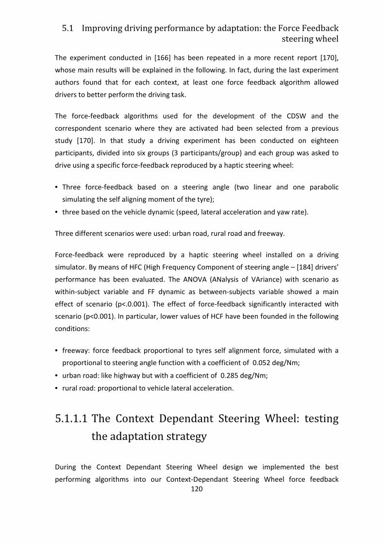
5.1 Improving driving performance by adaptation: the Force Feedback
steering wheel
120
The experiment conducted in [166] has been repeated in a more recent report [170],
whose main results will be explained in the following. In fact, during the last experiment
authors found that for each context, at least one force feedback algorithm allowed
drivers to better perform the driving task.
The force-feedback algorithms used for the development of the CDSW and the
correspondent scenario where they are activated had been selected from a previous
study [170]. In that study a driving experiment has been conducted on eighteen
participants, divided into six groups (3 participants/group) and each group was asked to
drive using a specific force-feedback reproduced by a haptic steering wheel:
• Three force-feedback based on a steering angle (two linear and one parabolic
simulating the self aligning moment of the tyre);
• three based on the vehicle dynamic (speed, lateral acceleration and yaw rate).
Three different scenarios were used: urban road, rural road and freeway.
Force-feedback were reproduced by a haptic steering wheel installed on a driving
simulator. By means of HFC (High Frequency Component of steering angle – [184] drivers’
performance has been evaluated. The ANOVA (ANalysis of VAriance) with scenario as
within-subject variable and FF dynamic as between-subjects variable showed a main
effect of scenario (p<.0.001). The effect of force-feedback significantly interacted with
scenario (p<0.001). In particular, lower values of HCF have been founded in the following
conditions:
• freeway: force feedback proportional to tyres self alignment force, simulated with a
proportional to steering angle function with a coefficient of 0.052 deg/Nm;
• urban road: like highway but with a coefficient of 0.285 deg/Nm;
• rural road: proportional to vehicle lateral acceleration.
5.1.1.1 The Context Dependant Steering Wheel: testing
the adaptation strategy
During the Context Dependant Steering Wheel design we implemented the best
performing algorithms into our Context-Dependant Steering Wheel force feedback
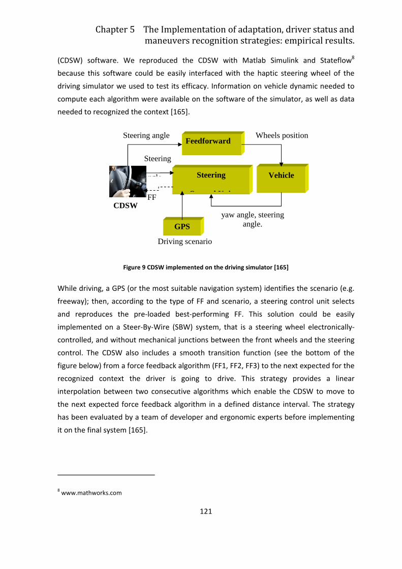
Chapter 5 The Implementation of adaptation, driver status and
maneuvers recognition strategies: empirical results.
121
(CDSW) software. We reproduced the CDSW with Matlab Simulink and Stateflow8
because this software could be easily interfaced with the haptic steering wheel of the
driving simulator we used to test its efficacy. Information on vehicle dynamic needed to
compute each algorithm were available on the software of the simulator, as well as data
needed to recognized the context [165].
Figure 9 CDSW implemented on the driving simulator [165]
While driving, a GPS (or the most suitable navigation system) identifies the scenario (e.g.
freeway); then, according to the type of FF and scenario, a steering control unit selects
and reproduces the pre-loaded best-performing FF. This solution could be easily
implemented on a Steer-By-Wire (SBW) system, that is a steering wheel electronically-
controlled, and without mechanical junctions between the front wheels and the steering
control. The CDSW also includes a smooth transition function (see the bottom of the
figure below) from a force feedback algorithm (FF1, FF2, FF3) to the next expected for the
recognized context the driver is going to drive. This strategy provides a linear
interpolation between two consecutive algorithms which enable the CDSW to move to
the next expected force feedback algorithm in a defined distance interval. The strategy
has been evaluated by a team of developer and ergonomic experts before implementing
it on the final system [165].
8 www.mathworks.com
Vehicle
yaw angle, steering angle.
Wheels position
GPS
FF
Feedforward
Steering
angle
Steering angle
Steering
Control Unit
Driving scenario
CDSW
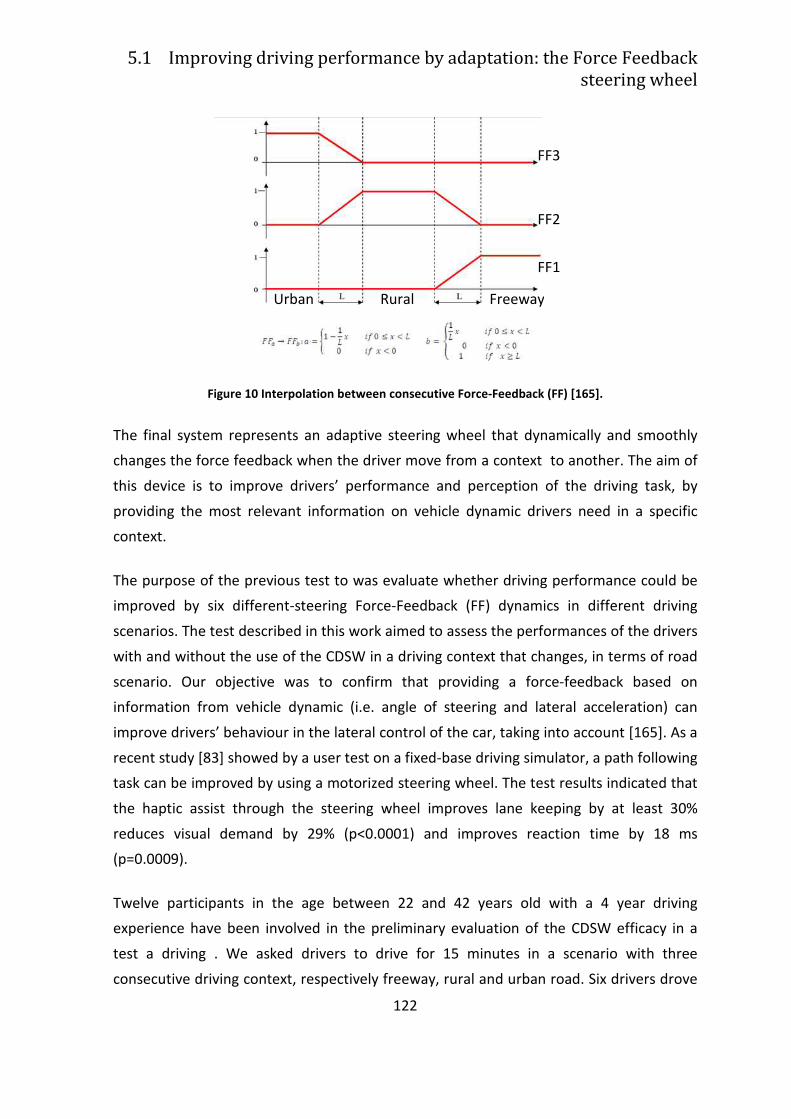
5.1 Improving driving performance by adaptation: the Force Feedback
steering wheel
122
Figure 10 Interpolation between consecutive Force-Feedback (FF) [165].
The final system represents an adaptive steering wheel that dynamically and smoothly
changes the force feedback when the driver move from a context to another. The aim of
this device is to improve drivers’ performance and perception of the driving task, by
providing the most relevant information on vehicle dynamic drivers need in a specific
context.
The purpose of the previous test to was evaluate whether driving performance could be
improved by six different-steering Force-Feedback (FF) dynamics in different driving
scenarios. The test described in this work aimed to assess the performances of the drivers
with and without the use of the CDSW in a driving context that changes, in terms of road
scenario. Our objective was to confirm that providing a force-feedback based on
information from vehicle dynamic (i.e. angle of steering and lateral acceleration) can
improve drivers’ behaviour in the lateral control of the car, taking into account [165]. As a
recent study [83] showed by a user test on a fixed-base driving simulator, a path following
task can be improved by using a motorized steering wheel. The test results indicated that
the haptic assist through the steering wheel improves lane keeping by at least 30%
reduces visual demand by 29% (p<0.0001) and improves reaction time by 18 ms
(p=0.0009).
Twelve participants in the age between 22 and 42 years old with a 4 year driving
experience have been involved in the preliminary evaluation of the CDSW efficacy in a
test a driving . We asked drivers to drive for 15 minutes in a scenario with three
consecutive driving context, respectively freeway, rural and urban road. Six drivers drove
Urban Rural Freeway
FF1
FF2
FF3
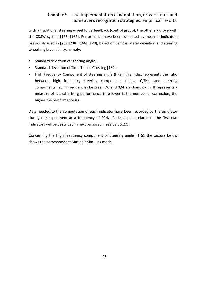
Chapter 5 The Implementation of adaptation, driver status and
maneuvers recognition strategies: empirical results.
123
with a traditional steering wheel force feedback (control group); the other six drove with
the CDSW system [165] [162]. Performance have been evaluated by mean of indicators
previously used in [239][238] [166] [170], based on vehicle lateral deviation and steering
wheel angle variability, namely:
• Standard deviation of Steering Angle;
• Standard deviation of Time To line Crossing [184];
• High Frequency Component of steering angle (HFS): this index represents the ratio
between high frequency steering components (above 0,3Hz) and steering
components having frequencies between DC and 0,6Hz as bandwidth. It represents a
measure of lateral driving performance (the lower is the number of correction, the
higher the performance is).
Data needed to the computation of each indicator have been recorded by the simulator
during the experiment at a frequency of 20Hz. Code snippet related to the first two
indicators will be described in next paragraph (see par. 5.2.1).
Concerning the High Frequency component of Steering angle (HFS), the picture below
shows the correspondent Matlab™ Simulink model.
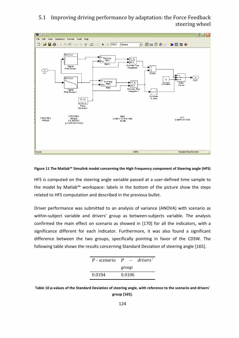
5.1 Improving driving performance by adaptation: the Force Feedback
steering wheel
124
Figure 11 The Matlab™ Simulink model concerning the High Frequency component of Steering angle (HFS)
HFS is computed on the steering angle variable passed at a user-defined time sample to
the model by Matlab™ workspace: labels in the bottom of the picture show the steps
related to HFS computation and described in the previous bullet.
Driver performance was submitted to an analysis of variance (ANOVA) with scenario as
within-subject variable and drivers’ group as between-subjects variable. The analysis
confirmed the main effect on scenario as showed in [170] for all the indicators, with a
significance different for each indicator. Furthermore, it was also found a significant
difference between the two groups, specifically pointing in favor of the CDSW. The
following table shows the results concerning Standard Deviation of steering angle [165].
P - scenario P – drivers’
group
0.0194 0.0106
Table 10 p-values of the Standard Deviation of steering angle, with reference to the scenario and drivers'
group [165].
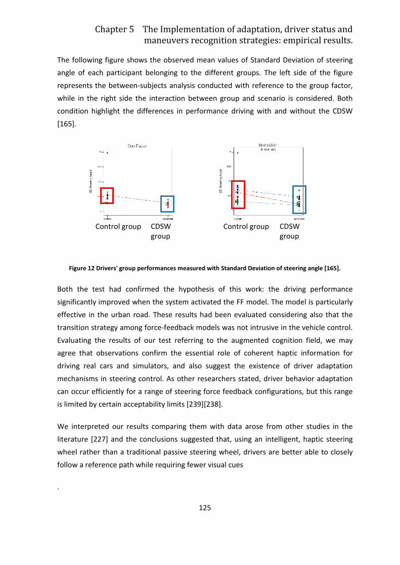
Chapter 5 The Implementation of adaptation, driver status and
maneuvers recognition strategies: empirical results.
125
The following figure shows the observed mean values of Standard Deviation of steering
angle of each participant belonging to the different groups. The left side of the figure
represents the between-subjects analysis conducted with reference to the group factor,
while in the right side the interaction between group and scenario is considered. Both
condition highlight the differences in performance driving with and without the CDSW
[165].
Figure 12 Drivers' group performances measured with Standard Deviation of steering angle [165].
Both the test had confirmed the hypothesis of this work: the driving performance
significantly improved when the system activated the FF model. The model is particularly
effective in the urban road. These results had been evaluated considering also that the
transition strategy among force-feedback models was not intrusive in the vehicle control.
Evaluating the results of our test referring to the augmented cognition field, we may
agree that observations confirm the essential role of coherent haptic information for
driving real cars and simulators, and also suggest the existence of driver adaptation
mechanisms in steering control. As other researchers stated, driver behavior adaptation
can occur efficiently for a range of steering force feedback configurations, but this range
is limited by certain acceptability limits [239][238].
We interpreted our results comparing them with data arose from other studies in the
literature [227] and the conclusions suggested that, using an intelligent, haptic steering
wheel rather than a traditional passive steering wheel, drivers are better able to closely
follow a reference path while requiring fewer visual cues
.
Control group CDSW group
Control group CDSW group
126
5.2 Assessing driver’s status: how to improve
adaptation by driver’s model trigger.
Data on driver, vehicle and environment provided by on-board devices (e.g. radars and
sensors for vehicle dynamic and road characteristics detection) represent a feasible way
to derive the level of distraction. This data can be recorded in real-time during driving.
This kind of approach has been followed by the HMI Group of University of Modena and
Reggio Emilia during the Aide project.
AIDE stands for Adaptive Integrated Driver-vehicle InterfacE and it was a project funded
whitin the Sixt Framework Program by the European Commission (www.aide-eu.org).
Its aim was to generate the knowledge and develop methodologies and human-machine
interface technologies required for safe and efficient integration of ADAS, IVIS and nomad
devices into the driving environment. Specifically, the project was aimed at designing,
developing and validating a generic Adaptive Integrated Driver-vehicle InterfacE (AIDE)
able to employ innovative concepts and technologies in order to:
1. maximise the efficiency, and hence the safety benefits, of advanced driver
assistance systems,
2. minimise the level of workload and distraction imposed by in-vehicle information
systems and nomad devices
3. enable the potential benefits of new in-vehicle technologies and nomad devices
in terms of mobility and comfort, without compromising safety.
During this work, we selected these data as inputs of the drivers’ distraction model,
basing on expert opinion and literature. As for the target to be used to train, validate and
test the distraction model following machine learning techniques, we adopted the time
spent by the driver watching the secondary task, according to [154]. This measures the
time drivers’ gaze is focused on the display where the secondary task is displayed. As
described in the DVE model in the previous chapter (see paragraph 4.3), this time has
been set to 2 seconds; during the simulator experiments, a time gaze higher than 2
seconds denoted a distracted driver.
Chapter 5 The Implementation of adaptation, driver status and
maneuvers recognition strategies: empirical results.
127
The first formulation of the model has been developed using a Fuzzy Inference System
[213]. This approach required to define:
• Model inputs;
• Model target;
• Mathematical relationships between inputs and target.
Model inputs have been defined as follows [235]:
• Level of difficulty of an IVIS (In-Vehicle Information System) reproducing a visual
research task: the secondary task we reproduced was the SUrrugate Research Task
[154] emulating the research task of a car navigator system (e.g. to find a destination
on the touch screen of a navigator).
• Level of traffic density according to [13] driver distraction from the primary task, due
to the activation and interaction with on-board devices could increase with the level
of traffic density.
Relationships have been defined using the machine learning techniques that, basing on
inputs and target data recorded during a simulator experiment further described, tried to
map inputs to the target following three steps: training, validation and testing.
In the first two steps the model of distraction is created: in the latter the model is tested,
that is, it tries to predict the target basing on new inputs data. The performances of this
prediction have been assessed using two specific indicator, namely MSE (Mean Square
Error) and RMSE (Root Mean Square Error), able to measure the differences between the
prediction done by the trained and validated distraction model and the target .
Other formulations of distraction have been developed by combining several inputs in
order to find the model with highest performance (i.e. RMSE, MSE) values. Inputs have
been selected among a set of on-line measures which could describe drivers’ behaviour
impairment on the road due to the interaction with a secondary task [185]:
• Standard deviation of Speed (SDSPEED);
• Standard Deviation of Steering Angle (SDSA);
• Standard Deviation of Lateral Position (SDLP);
• Standard Deviation of Lateral Acceleration (SDSA);
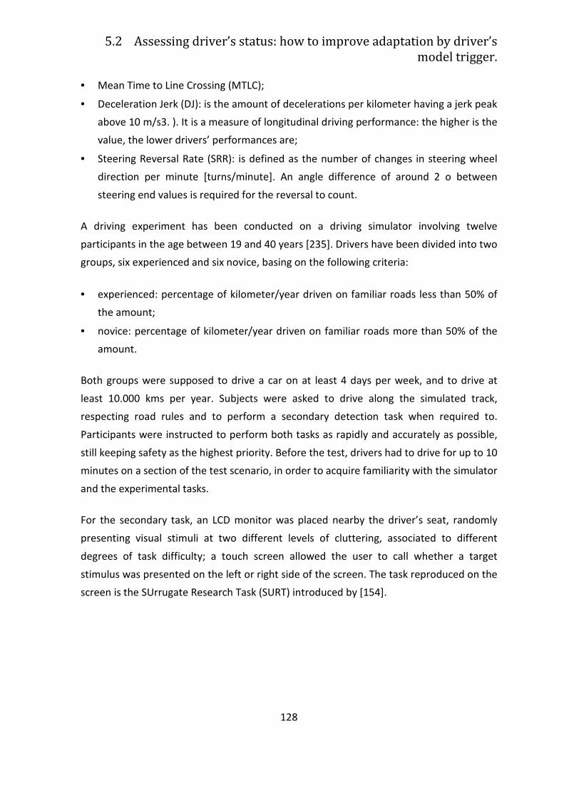
5.2 Assessing driver’s status: how to improve adaptation by driver’s
model trigger.
128
• Mean Time to Line Crossing (MTLC);
• Deceleration Jerk (DJ): is the amount of decelerations per kilometer having a jerk peak
above 10 m/s3. ). It is a measure of longitudinal driving performance: the higher is the
value, the lower drivers’ performances are;
• Steering Reversal Rate (SRR): is defined as the number of changes in steering wheel
direction per minute [turns/minute]. An angle difference of around 2 o between
steering end values is required for the reversal to count.
A driving experiment has been conducted on a driving simulator involving twelve
participants in the age between 19 and 40 years [235]. Drivers have been divided into two
groups, six experienced and six novice, basing on the following criteria:
• experienced: percentage of kilometer/year driven on familiar roads less than 50% of
the amount;
• novice: percentage of kilometer/year driven on familiar roads more than 50% of the
amount.
Both groups were supposed to drive a car on at least 4 days per week, and to drive at
least 10.000 kms per year. Subjects were asked to drive along the simulated track,
respecting road rules and to perform a secondary detection task when required to.
Participants were instructed to perform both tasks as rapidly and accurately as possible,
still keeping safety as the highest priority. Before the test, drivers had to drive for up to 10
minutes on a section of the test scenario, in order to acquire familiarity with the simulator
and the experimental tasks.
For the secondary task, an LCD monitor was placed nearby the driver’s seat, randomly
presenting visual stimuli at two different levels of cluttering, associated to different
degrees of task difficulty; a touch screen allowed the user to call whether a target
stimulus was presented on the left or right side of the screen. The task reproduced on the
screen is the SUrrugate Research Task (SURT) introduced by [154].
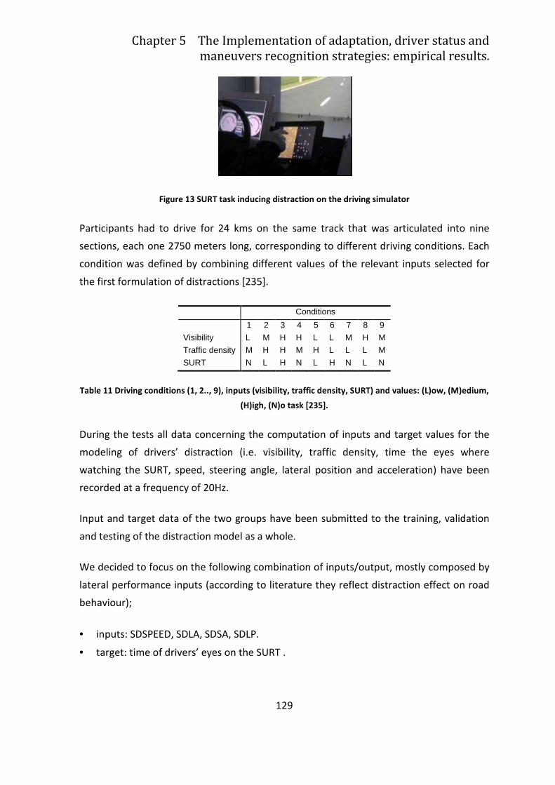
Chapter 5 The Implementation of adaptation, driver status and
maneuvers recognition strategies: empirical results.
129
Figure 13 SURT task inducing distraction on the driving simulator
Participants had to drive for 24 kms on the same track that was articulated into nine
sections, each one 2750 meters long, corresponding to different driving conditions. Each
condition was defined by combining different values of the relevant inputs selected for
the first formulation of distractions [235].
Conditions
1 2 3 4 5 6 7 8 9
Visibility L M H H L L M H M Traffic density M H H M H L L L M SURT N L H N L H N L N
Table 11 Driving conditions (1, 2.., 9), inputs (visibility, traffic density, SURT) and values: (L)ow, (M)edium,
(H)igh, (N)o task [235].
During the tests all data concerning the computation of inputs and target values for the
modeling of drivers’ distraction (i.e. visibility, traffic density, time the eyes where
watching the SURT, speed, steering angle, lateral position and acceleration) have been
recorded at a frequency of 20Hz.
Input and target data of the two groups have been submitted to the training, validation
and testing of the distraction model as a whole.
We decided to focus on the following combination of inputs/output, mostly composed by
lateral performance inputs (according to literature they reflect distraction effect on road
behaviour);
• inputs: SDSPEED, SDLA, SDSA, SDLP.
• target: time of drivers’ eyes on the SURT .
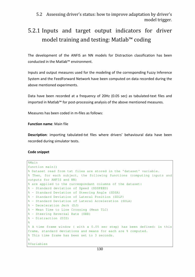
5.2 Assessing driver’s status: how to improve adaptation by driver’s
model trigger.
130
5.2.1 Inputs and target output indicators for driver
model training and testing: Matlab™ coding
The development of the ANFIS an NN models for Distraction classification has been
conducted in the Matlab™ environment.
Inputs and output measures used for the modeling of the corresponding Fuzzy Inference
System and the FeedForward Network have been computed on data recorded during the
above mentioned experiments.
Data have been recorded at a frequency of 20Hz (0.05 sec) as tabulated-text files and
imported in Matlab™ for post-processing analysis of the above mentioned measures.
Measures has been coded in m-files as follows:
Function name: Main file
Description: importing tabulated-txt files where drivers’ behavioural data have been
recorded during simulator tests.
Code snippet
%Main function main() % Dataset read from txt files are stored in the "da taset" variable. % Then, for each subject, the following functions ( computing inputs and outputs for ANFIS and NN) % are applied to the currespondant columns of the d ataset: % - Standard deviation of Speed (SDSPEED) % - Standard Deviation of Steering Angle (SDSA) % - Standard Deviation of Lateral Position (SDLP) % - Standard Deviation of Lateral Acceleration (SDL A) % - Deceleration Jerk (DJ) % - Mean Time to Line Crossing (Mean TLC) % - Steering Reversal Rate (SRR) % - Distraction (DIS) % % A time frame window ( with a 0.05 sec step) has b een defined: in this frame, standard deviations and means for each are % computed. % This time frame has been set to 3 seconds. % %Variables
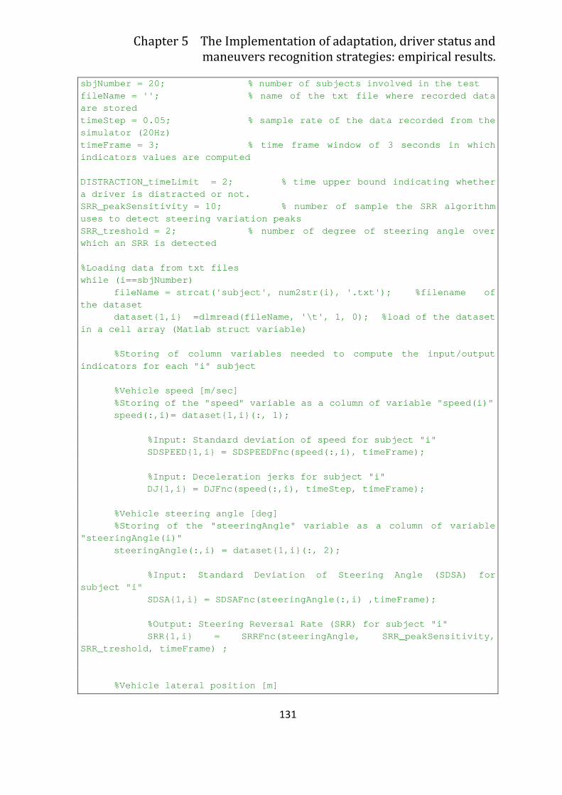
Chapter 5 The Implementation of adaptation, driver status and
maneuvers recognition strategies: empirical results.
131
sbjNumber = 20; % number of subjects involved in the test fileName = ''; % name of the txt file where recor ded data are stored timeStep = 0.05; % sample rate of the data record ed from the simulator (20Hz) timeFrame = 3; % time frame window of 3 seconds i n which indicators values are computed DISTRACTION_timeLimit = 2; % time upper bound ind icating whether a driver is distracted or not. SRR_peakSensitivity = 10; % number of sample the S RR algorithm uses to detect steering variation peaks SRR_treshold = 2; % number of degree of steering angle over which an SRR is detected %Loading data from txt files while (i==sbjNumber) fileName = strcat('subject', num2str(i), '.txt'); %filename of the dataset dataset{1,i} =dlmread(fileName, '\t', 1, 0); %loa d of the dataset in a cell array (Matlab struct variable) %Storing of column variables needed to compute the input/output indicators for each "i" subject %Vehicle speed [m/sec] %Storing of the "speed" variable as a column of va riable "speed(i)" speed(:,i)= dataset{1,i}(:, 1); %Input: Standard deviation of speed for subject " i" SDSPEED{1,i} = SDSPEEDFnc(speed(:,i), timeFrame); %Input: Deceleration jerks for subject "i" DJ{1,i} = DJFnc(speed(:,i), timeStep, timeFrame); %Vehicle steering angle [deg] %Storing of the "steeringAngle" variable as a colu mn of variable "steeringAngle(i)" steeringAngle(:,i) = dataset{1,i}(:, 2); %Input: Standard Deviation of Steering Angle (SDS A) for subject "i" SDSA{1,i} = SDSAFnc(steeringAngle(:,i) ,timeFrame ); %Output: Steering Reversal Rate (SRR) for subject "i" SRR{1,i} = SRRFnc(steeringAngle, SRR_peakSensitiv ity, SRR_treshold, timeFrame) ; %Vehicle lateral position [m]
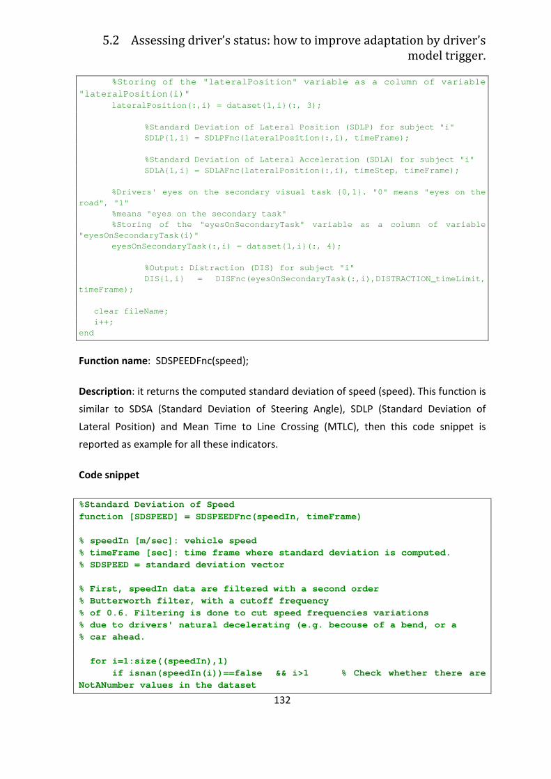
5.2 Assessing driver’s status: how to improve adaptation by driver’s
model trigger.
132
%Storing of the "lateralPosition" variable as a co lumn of variable "lateralPosition(i)" lateralPosition(:,i) = dataset{1,i}(:, 3); %Standard Deviation of Lateral Position (SDLP) fo r subject "i" SDLP{1,i} = SDLPFnc(lateralPosition(:,i), timeFra me); %Standard Deviation of Lateral Acceleration (SDLA ) for subject "i" SDLA{1,i} = SDLAFnc(lateralPosition(:,i), timeSte p, timeFrame);
%Drivers' eyes on the secondary visual task {0,1}. "0" means "eyes on the road", "1"
%means "eyes on the secondary task" %Storing of the "eyesOnSecondaryTask" variable as a column of variable "eyesOnSecondaryTask(i)" eyesOnSecondaryTask(:,i) = dataset{1,i}(:, 4); %Output: Distraction (DIS) for subject "i" DIS{1,i} = DISFnc(eyesOnSecondaryTask(:,i),DISTRA CTION_timeLimit, timeFrame); clear fileName; i++; end
Function name: SDSPEEDFnc(speed);
Description: it returns the computed standard deviation of speed (speed). This function is
similar to SDSA (Standard Deviation of Steering Angle), SDLP (Standard Deviation of
Lateral Position) and Mean Time to Line Crossing (MTLC), then this code snippet is
reported as example for all these indicators.
Code snippet
%Standard Deviation of Speed function [SDSPEED] = SDSPEEDFnc(speedIn, timeFrame) % speedIn [m/sec]: vehicle speed % timeFrame [sec]: time frame where standard deviat ion is computed. % SDSPEED = standard deviation vector % First, speedIn data are filtered with a second or der % Butterworth filter, with a cutoff frequency % of 0.6. Filtering is done to cut speed frequencie s variations % due to drivers' natural decelerating (e.g. becous e of a bend, or a % car ahead. for i=1:size((speedIn),1) if isnan(speedIn(i))==false && i>1 % Check wh ether there are NotANumber values in the dataset
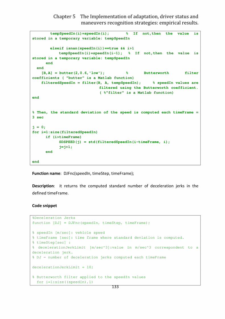
Chapter 5 The Implementation of adaptation, driver status and
maneuvers recognition strategies: empirical results.
133
tempSpeedIn(i)=speedIn(i); % If not,then t he value is stored in a temporary variable: tempSpeedIn elseif isnan(speedIn(i))==true && i>1 tempSpeedIn(i)=speedIn(i-1); % If not,then the v alue is stored in a temporary variable: tempSpeedIn end end [B,A] = butter(2,0.6,'low'); % Butterworth fil ter coefficients ( "butter" is a Matlab function) filteredSpeedIn = filter(B, A, tempSpeedIn); % speedIn values are
filtered using the Butterworth coefficient. ( %"filter" is a Matlab function)
end % Then, the standard deviation of the speed is comp uted each timeFrame = 3 sec j = 0; for i=1:size(filteredSpeedIn) if (i>timeFrame) SDSPEED(j) = std(filteredSpeedIn(i-timeFrame, i); j=j+1; end end
Function name: DJFnc(speedIn, timeStep, timeFrame);
Description: it returns the computed standard number of deceleration jerks in the
defined timeFrame.
Code snippet
%Deceleration Jerks function [DJ] = DJFnc(speedIn, timeStep, timeFrame) ; % speedIn [m/sec]: vehicle speed % timeFrame [sec]: time frame where standard deviat ion is computed. % timeStep[sec] : % decelerationJerkLimit [m/sec^3]:value in m/sec^3 correspondent to a deceleration jerk. % DJ = number of deceleration jerks computed each t imeFrame decelerationJerkLimit = 10; % Butterworth filter applied to the speedIn values for i=1:size((speedIn),1)
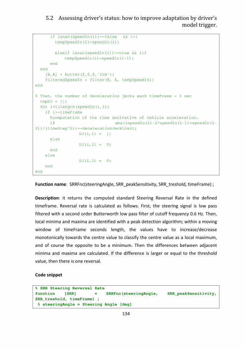
5.2 Assessing driver’s status: how to improve adaptation by driver’s
model trigger.
134
if isnan(speedIn(i))==false && i>1 tempSpeedIn(i)=speedIn(i); elseif isnan(speedIn(i))==true && i>1 tempSpeedIn(i)=speedIn(i-1); end end [B,A] = butter(2,0.6,'low'); filteredSpeedIn = filter(B, A, tempSpeedIn); end % Then, the number of deceleration jerks each timeF rame = 3 sec tmpDJ = []; for i=1:length(speedIn(:,1)) if i>=timeFrame %computation of the time derivative of vehicle acc eleration. if abs((speedIn(i)-2*speedIn(i-1)+speedIn(i-2))/(timeStep^2))>=decelerationJerkLimit; DJ(i,1) = 1; else DJ(i,1) = 0; end else DJ(i,1) = 0; end end
Function name: SRRFnc(steeringAngle, SRR_peakSensitivity, SRR_treshold, timeFrame) ;
Description: it returns the computed standard Steering Reversal Rate in the defined
timeframe. Reversal rate is calculated as follows. First, the steering signal is low pass
filtered with a second order Butterworth low pass filter of cutoff frequency 0.6 Hz. Then,
local minima and maxima are identified with a peak detection algorithm; within a moving
window of timeFrame seconds length, the values have to increase/decrease
monotonically towards the centre value to classify the centre value as a local maximum,
and of course the opposite to be a minimum. Then the differences between adjacent
minima and maxima are calculated. If the difference is larger or equal to the threshold
value, then there is one reversal.
Code snippet
% SRR Steering Reversal Rate function [SRR] = SRRFnc(steeringAngle, SRR_peakSen sitivity, SRR_treshold, timeFrame) ; % steeringAngle = Steering Angle [deg]
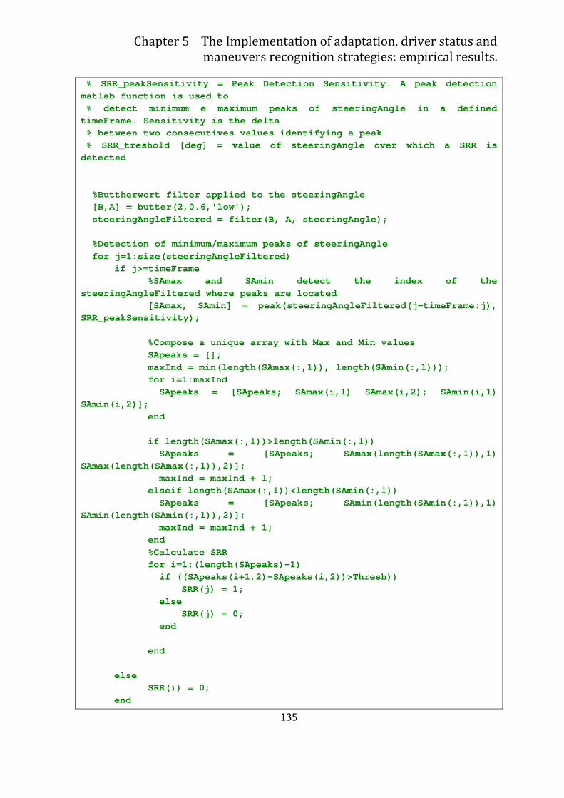
Chapter 5 The Implementation of adaptation, driver status and
maneuvers recognition strategies: empirical results.
135
% SRR_peakSensitivity = Peak Detection Sensitivity . A peak detection matlab function is used to % detect minimum e maximum peaks of steeringAngle in a defined timeFrame. Sensitivity is the delta % between two consecutives values identifying a pe ak % SRR_treshold [deg] = value of steeringAngle over which a SRR is detected %Buttherwort filter applied to the steeringAngle [B,A] = butter(2,0.6,'low'); steeringAngleFiltered = filter(B, A, steeringAngl e); %Detection of minimum/maximum peaks of steeringAn gle for j=1:size(steeringAngleFiltered) if j>=timeFrame %SAmax and SAmin detect the index of the steeringAngleFiltered where peaks are located [SAmax, SAmin] = peak(steeringAngleFiltered(j-tim eFrame:j), SRR_peakSensitivity); %Compose a unique array with Max and Min values SApeaks = []; maxInd = min(length(SAmax(:,1)), length(SAmin(:,1 ))); for i=1:maxInd SApeaks = [SApeaks; SAmax(i,1) SAmax(i,2); SAmi n(i,1) SAmin(i,2)]; end if length(SAmax(:,1))>length(SAmin(:,1)) SApeaks = [SApeaks; SAmax(length(SAmax(:,1)),1) SAmax(length(SAmax(:,1)),2)]; maxInd = maxInd + 1; elseif length(SAmax(:,1))<length(SAmin(:,1)) SApeaks = [SApeaks; SAmin(length(SAmin(:,1)),1) SAmin(length(SAmin(:,1)),2)]; maxInd = maxInd + 1; end %Calculate SRR for i=1:(length(SApeaks)-1) if ((SApeaks(i+1,2)-SApeaks(i,2))>Thresh)) SRR(j) = 1; else SRR(j) = 0; end end else SRR(i) = 0; end
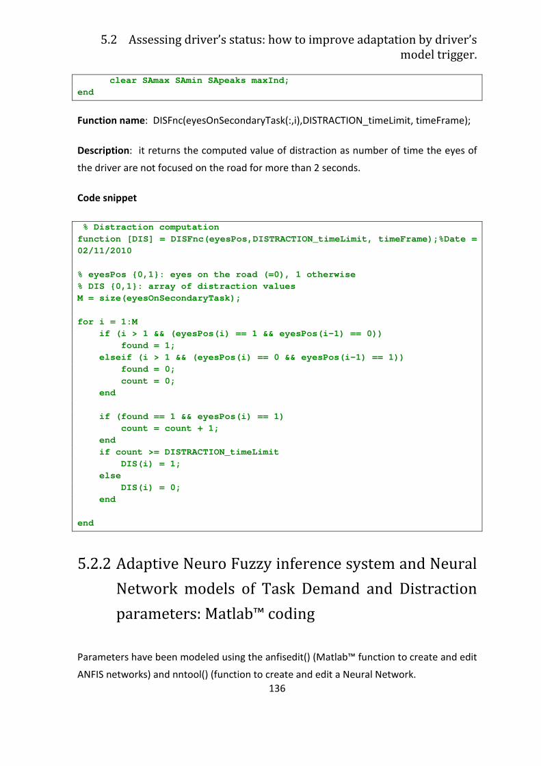
5.2 Assessing driver’s status: how to improve adaptation by driver’s
model trigger.
136
clear SAmax SAmin SApeaks maxInd; end
Function name: DISFnc(eyesOnSecondaryTask(:,i),DISTRACTION_timeLimit, timeFrame);
Description: it returns the computed value of distraction as number of time the eyes of
the driver are not focused on the road for more than 2 seconds.
Code snippet
% Distraction computation function [DIS] = DISFnc(eyesPos,DISTRACTION_timeLim it, timeFrame);%Date = 02/11/2010 % eyesPos {0,1}: eyes on the road (=0), 1 otherwise % DIS {0,1}: array of distraction values M = size(eyesOnSecondaryTask); for i = 1:M if (i > 1 && (eyesPos(i) == 1 && eyesPos(i-1) = = 0)) found = 1; elseif (i > 1 && (eyesPos(i) == 0 && eyesPos(i- 1) == 1)) found = 0; count = 0; end if (found == 1 && eyesPos(i) == 1) count = count + 1; end if count >= DISTRACTION_timeLimit DIS(i) = 1; else DIS(i) = 0; end end
5.2.2 Adaptive Neuro Fuzzy inference system and Neural
Network models of Task Demand and Distraction
parameters: Matlab™ coding
Parameters have been modeled using the anfisedit() (Matlab™ function to create and edit
ANFIS networks) and nntool() (function to create and edit a Neural Network.
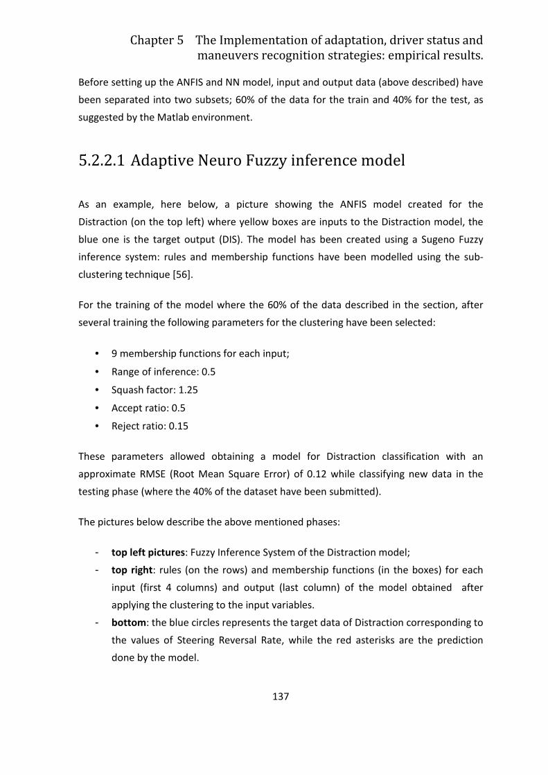
Chapter 5 The Implementation of adaptation, driver status and
maneuvers recognition strategies: empirical results.
137
Before setting up the ANFIS and NN model, input and output data (above described) have
been separated into two subsets; 60% of the data for the train and 40% for the test, as
suggested by the Matlab environment.
5.2.2.1 Adaptive Neuro Fuzzy inference model
As an example, here below, a picture showing the ANFIS model created for the
Distraction (on the top left) where yellow boxes are inputs to the Distraction model, the
blue one is the target output (DIS). The model has been created using a Sugeno Fuzzy
inference system: rules and membership functions have been modelled using the sub-
clustering technique [56].
For the training of the model where the 60% of the data described in the section, after
several training the following parameters for the clustering have been selected:
• 9 membership functions for each input;
• Range of inference: 0.5
• Squash factor: 1.25
• Accept ratio: 0.5
• Reject ratio: 0.15
These parameters allowed obtaining a model for Distraction classification with an
approximate RMSE (Root Mean Square Error) of 0.12 while classifying new data in the
testing phase (where the 40% of the dataset have been submitted).
The pictures below describe the above mentioned phases:
- top left pictures: Fuzzy Inference System of the Distraction model;
- top right: rules (on the rows) and membership functions (in the boxes) for each
input (first 4 columns) and output (last column) of the model obtained after
applying the clustering to the input variables.
- bottom: the blue circles represents the target data of Distraction corresponding to
the values of Steering Reversal Rate, while the red asterisks are the prediction
done by the model.
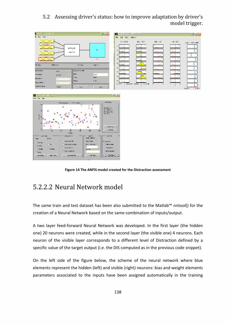
5.2 Assessing driver’s status: how to improve adaptation by driver’s
model trigger.
138
Figure 14 The ANFIS model created for the Distraction assessment
5.2.2.2 Neural Network model
The same train and test dataset has been also submitted to the Matlab™ nntool() for the
creation of a Neural Network based on the same combination of inputs/output.
A two layer feed-forward Neural Network was developed. In the first layer (the hidden
one) 20 neurons were created, while in the second layer (the visible one) 4 neurons. Each
neuron of the visible layer corresponds to a different level of Distraction defined by a
specific value of the target output (i.e. the DIS computed as in the previous code snippet).
On the left side of the figure below, the scheme of the neural network where blue
elements represent the hidden (left) and visible (right) neurons: bias and weight elements
parameters associated to the inputs have been assigned automatically in the training
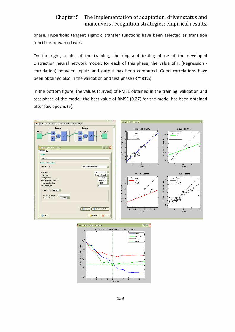
Chapter 5 The Implementation of adaptation, driver status and
maneuvers recognition strategies: empirical results.
139
phase. Hyperbolic tangent sigmoid transfer functions have been selected as transition
functions between layers.
On the right, a plot of the training, checking and testing phase of the developed
Distraction neural network model; for each of this phase, the value of R (Regression -
correlation) between inputs and output has been computed. Good correlations have
been obtained also in the validation and test phase (R ~ 81%).
In the bottom figure, the values (curves) of RMSE obtained in the training, validation and
test phase of the model; the best value of RMSE (0.27) for the model has been obtained
after few epochs (5).
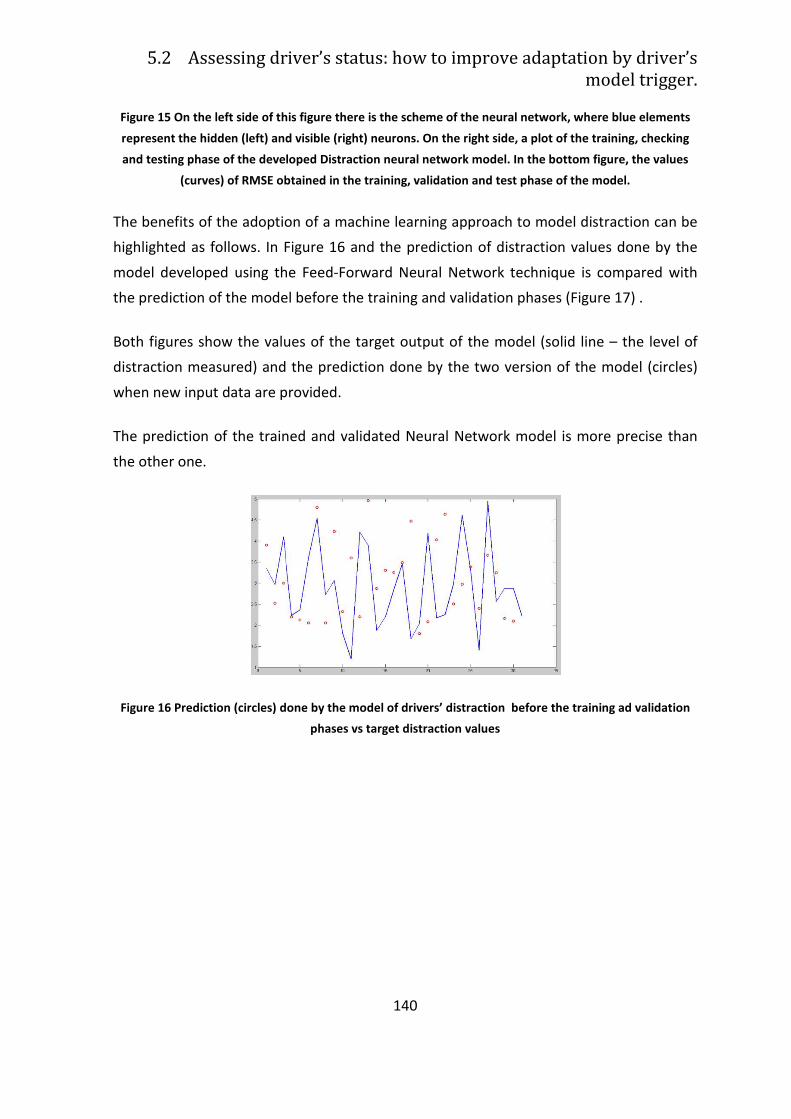
5.2 Assessing driver’s status: how to improve
Figure 15 On the left side of this
represent the hidden (left) and visible (right) neurons. On the right
and testing phase of the developed Distraction neural network model. In the bottom figure
(curves) of RMSE obtained in the training, validation and test phase of the model
The benefits of the adoption of a machine learning approach to model distraction can be
highlighted as follows. In Figure
model developed using the Feed
the prediction of the model before the training and validation phases (
Both figures show the values of the target output of the model (solid line
distraction measured) and the prediction done by the two version of the model (circles)
when new input data are p
The prediction of the trained and validated Neural Network model is more precise than
the other one.
Figure 16 Prediction (circles) done by the model of drivers’ distraction before the training ad validation
Assessing driver’s status: how to improve adaptation by driver’s
140
his figure there is the scheme of the neural network,
represent the hidden (left) and visible (right) neurons. On the right side, a plot of the training, checking
and testing phase of the developed Distraction neural network model. In the bottom figure
(curves) of RMSE obtained in the training, validation and test phase of the model
The benefits of the adoption of a machine learning approach to model distraction can be
Figure 16 and the prediction of distraction values done by the
model developed using the Feed-Forward Neural Network technique is compared with
the prediction of the model before the training and validation phases (Figure
Both figures show the values of the target output of the model (solid line
distraction measured) and the prediction done by the two version of the model (circles)
when new input data are provided.
The prediction of the trained and validated Neural Network model is more precise than
Prediction (circles) done by the model of drivers’ distraction before the training ad validation
phases vs target distraction values
adaptation by driver’s
model trigger.
where blue elements
, a plot of the training, checking
and testing phase of the developed Distraction neural network model. In the bottom figure, the values
(curves) of RMSE obtained in the training, validation and test phase of the model.
The benefits of the adoption of a machine learning approach to model distraction can be
and the prediction of distraction values done by the
Forward Neural Network technique is compared with
Figure 17) .
Both figures show the values of the target output of the model (solid line – the level of
distraction measured) and the prediction done by the two version of the model (circles)
The prediction of the trained and validated Neural Network model is more precise than
Prediction (circles) done by the model of drivers’ distraction before the training ad validation
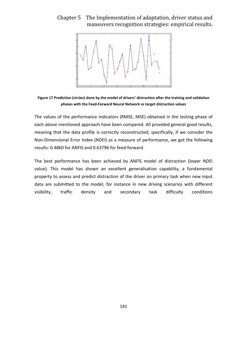
Chapter 5 The Implementation of adaptation, driver status and
maneuvers recognition strategies: empirical results.
Figure 17 Prediction (circles) done by the model of drivers’ distraction after the training and validation
phases with the Feed
The values of the performance indicators (RMSE, MSE) obtained in the testing phase of
each above mentioned approach have been compared
meaning that the data profile is correctly reconstructed; specifically, if we consider the
Non-Dimensional Error Index (NDEI) as a measure of performance, we got the following
results: 0.4860 for ANFIS and 0.63796 for feed
The best performance has been achieved by ANFIS model of distraction (lower NDEI
value). This model has shown an excellent generalisation capability, a fundamental
property to assess and predict distraction of the driver on primary task when new input
data are submitted to the model, for instance in new driving scenarios with different
visibility, traffic density and secondary task difficulty conditions
The Implementation of adaptation, driver status and
maneuvers recognition strategies: empirical results.
141
Prediction (circles) done by the model of drivers’ distraction after the training and validation
phases with the Feed-Forward Neural Network vs target distraction values
mance indicators (RMSE, MSE) obtained in the testing phase of
each above mentioned approach have been compared. All provided general good results,
meaning that the data profile is correctly reconstructed; specifically, if we consider the
ror Index (NDEI) as a measure of performance, we got the following
results: 0.4860 for ANFIS and 0.63796 for feed-forward.
The best performance has been achieved by ANFIS model of distraction (lower NDEI
value). This model has shown an excellent generalisation capability, a fundamental
predict distraction of the driver on primary task when new input
data are submitted to the model, for instance in new driving scenarios with different
visibility, traffic density and secondary task difficulty conditions
The Implementation of adaptation, driver status and
maneuvers recognition strategies: empirical results.
Prediction (circles) done by the model of drivers’ distraction after the training and validation
distraction values
mance indicators (RMSE, MSE) obtained in the testing phase of
provided general good results,
meaning that the data profile is correctly reconstructed; specifically, if we consider the
ror Index (NDEI) as a measure of performance, we got the following
The best performance has been achieved by ANFIS model of distraction (lower NDEI
value). This model has shown an excellent generalisation capability, a fundamental
predict distraction of the driver on primary task when new input
data are submitted to the model, for instance in new driving scenarios with different
visibility, traffic density and secondary task difficulty conditions
142
5.3 Understanding driver’s maneuvers by the
use of Add. On Functionalities
Research in driver comfort and performance improvement understanding driver’s
maneuvers is very active. Usually, these targets are achieved through the installation of
further in-vehicle sensors and devices [149].
A feasible alternative is the use of the so-called Add-On Functionalities (AOF). They do not
require new sensors but only information coming from the on-board network and sub-
systems (e.g. the elements of chassis, suspensions, steering angle, etc.). The information
computeby by a proper algorhitm provides some added-value supports to the drivers as
AOFs for pre-crash detection. They prepare the vehicle to the impact in critical situation
which can not be avoided, for example, by pre-tensioning the seat belt [149].
Add-On Functionalities can be divided in two main categories:
• Driving Behaviour: i.e. Add-On Functionalities related to driving performance.
Main objective of these AOF is to estimate driving conditions concerning road,
dynamics and current manoeuvre.
• Driver Behaviour: these AOF deal with driver current state, mainly intended as
mental effort (or workload) related to the driving task.
5.3.1 Driving behaviour
From a mechanical point of view, driving behaviour can be estimated analyzing vehicle
surrounding environment and vehicle behaviour in terms of:
• Road Conditions: estimation of road pattern (e.g. wave length, signal strength)
and development of algorithms for road typology identification. For example:
o Normal Road
o Bumpy Road
o HighWay
Chapter 5 The Implementation of adaptation, driver status and
maneuvers recognition strategies: empirical results.
143
Road roughness can be considered as a wave signal having typical frequencies and RMSE
(Root Mean Square Error). Consequently road analysis can be performed by a frequency
(e.g. Fourier Analysis) and by amplitude analysis.
• Manouevre Identification using vehicle data (e.g. speed, steering activity) specific
manoeuvers like:
o Normal driving
o Car Following
o Single and double Lane Change
This analysis is similar to Road Pattern detection, and can be performed by using special
classifiers, namely Support Vector Machines and Hidden Markov Models.
Prevemptive Roll Compensation: Such an AOF can be successfully adopted to produce
lateral acceleration compensation using Electric Roll Compensator (ERC) as a roll actuator
for comfort enhancement.
Roll/Pitch Rate Control: this AOF combines vehicle roll and pitch rate data in order to act
a Skyhook strategy9 involving four semi-active suspensions for rate mitigation and
comfort enhancement.
9 With active, semi-active or adaptive suspension it is possible to control the vertical movement of the
wheels via an onboard system rather than the movement being determined entirely by the surface on
which the car is driving. The system then virtually eliminates body roll and pitch variation in many driving
situations including cornering, accelerating, and braking. In this way a higher degree of both ride quality and
car handling is reached by keeping the tires perpendicular to the road in corners, allowing for much higher
levels of grip and control. An onboard computer detects body movement from sensors located throughout
the vehicle and, using data calculated by opportune control techniques, controls the action of the
suspension. Large number of studies how the effectiveness of the skyhook control policy in terms of its
ability to isolate the suspended mass from the base excitations. For details see[103]
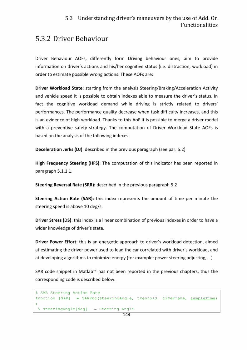
5.3 Understanding driver’s maneuvers by the use of Add. On
Functionalities
144
5.3.2 Driver Behaviour
Driver Behaviour AOFs, differently form Driving behaviour ones, aim to provide
information on driver’s actions and his/her cognitive status (i.e. distraction, workload) in
order to estimate possible wrong actions. These AOFs are:
Driver Workload State: starting from the analysis Steering/Braking/Acceleration Activity
and vehicle speed it is possible to obtain indexes able to measure the driver’s status. In
fact the cognitive workload demand while driving is strictly related to drivers’
performances. The performance quality decrease when task difficulty increases, and this
is an evidence of high workload. Thanks to this AoF it is possible to merge a driver model
with a preventive safety strategy. The computation of Driver Workload State AOFs is
based on the analysis of the following indexes:
Deceleration Jerks (DJ): described in the previous paragraph (see par. 5.2)
High Frequency Steering (HFS): The computation of this indicator has been reported in
paragraph 5.1.1.1.
Steering Reversal Rate (SRR): described in the previous paragraph 5.2
Steering Action Rate (SAR): this index represents the amount of time per minute the
steering speed is above 10 deg/s.
Driver Stress (DS): this index is a linear combination of previous indexes in order to have a
wider knowledge of driver’s state.
Driver Power Effort: this is an energetic approach to driver’s workload detection, aimed
at estimating the driver power used to lead the car correlated with driver’s workload, and
at developing algorithms to minimize energy (for example: power steering adjusting, …).
SAR code snippet in Matlab™ has not been reported in the previous chapters, thus the
corresponding code is described below.
% SAR Steering Action Rate function [SAR] = SARFnc(steeringAngle, treshold, t imeFrame, sampleTime ) ; % steeringAngle[deg] = Steering Angle
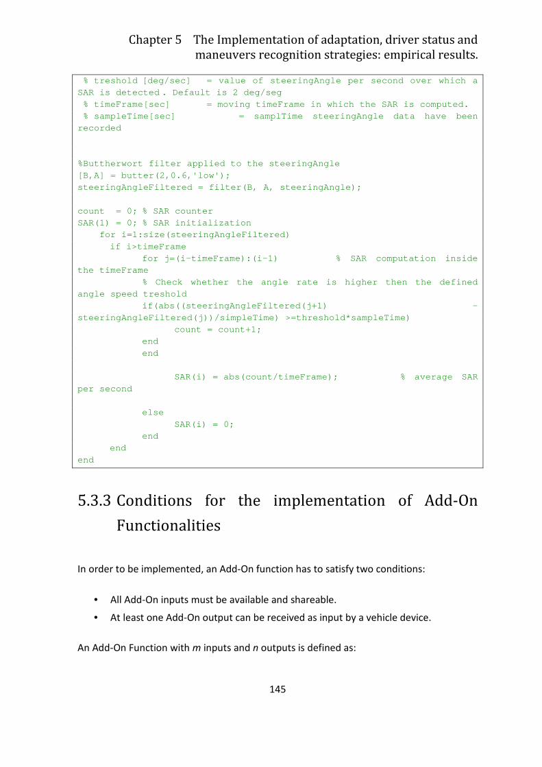
Chapter 5 The Implementation of adaptation, driver status and
maneuvers recognition strategies: empirical results.
145
% treshold [deg/sec] = value of steeringAngle per second over which a SAR is detected . Default is 2 deg/seg % timeFrame[sec] = moving timeFrame in which the SAR is computed. % sampleTime[sec] = samplTime steeringAngle data have been recorded %Buttherwort filter applied to the steeringAngle [B,A] = butter(2,0.6,'low'); steeringAngleFiltered = filter(B, A, steeringAngle) ; count = 0; % SAR counter SAR(1) = 0; % SAR initialization for i=1:size(steeringAngleFiltered) if i>timeFrame for j=(i-timeFrame):(i-1) % SAR computation insi de the timeFrame % Check whether the angle rate is higher then the defined angle speed treshold if(abs((steeringAngleFiltered(j+1) - steeringAngleFiltered(j))/simpleTime) >=threshold*s ampleTime) count = count+1; end end SAR(i) = abs(count/timeFrame); % average SAR per second else SAR(i) = 0; end end end
5.3.3 Conditions for the implementation of Add-On
Functionalities
In order to be implemented, an Add-On function has to satisfy two conditions:
• All Add-On inputs must be available and shareable.
• At least one Add-On output can be received as input by a vehicle device.
An Add-On Function with m inputs and n outputs is defined as:
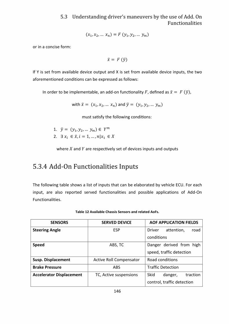
5.3 Understanding driver’s maneuvers by the use of Add. On
Functionalities
146
���, ��, … ��� � � ���, ��, … ���
or in a concise form:
�� � � ����
If Y is set from available device output and X is set from available device inputs, the two
aforementioned conditions can be expressed as follows:
In order to be implementable, an add‐on func_onality �, defined as �� � � ����,
with �� � ���, ��, … ��� and �� � ���, ��, … ���
must sa_sfy the following condi_ons:
1. �� � ���, ��, … ��� ��
2. �! ��, " � 1, … , $|�� &
where & and � are respec_vely set of devices inputs and outputs
5.3.4 Add-On Functionalities Inputs
The following table shows a list of inputs that can be elaborated by vehicle ECU. For each
input, are also reported served functionalities and possible applications of Add‐On
Functionalities.
Table 12 Available Chassis Sensors and related AoFs.
SENSORS SERVED DEVICE AOF APPLICATION FIELDS
Steering Angle ESP Driver attention, road
conditions
Speed ABS, TC Danger derived from high
speed, traffic detection
Susp. Displacement Active Roll Compensator Road conditions
Brake Pressure ABS Traffic Detection
Accelerator Displacement TC, Active suspensions Skid danger, traction
control, traffic detection
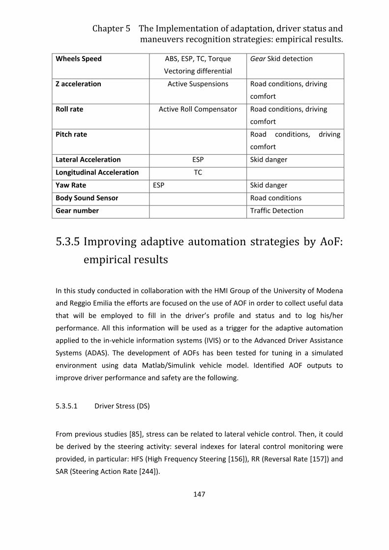
Chapter 5 The Implementation of adaptation, driver status and
maneuvers recognition strategies: empirical results.
147
Wheels Speed ABS, ESP, TC, Torque
Vectoring differential
Gear Skid detection
Z acceleration Active Suspensions Road conditions, driving
comfort
Roll rate Active Roll Compensator Road conditions, driving
comfort
Pitch rate Road conditions, driving
comfort
Lateral Acceleration ESP Skid danger
Longitudinal Acceleration TC
Yaw Rate ESP Skid danger
Body Sound Sensor Road conditions
Gear number Traffic Detection
5.3.5 Improving adaptive automation strategies by AoF:
empirical results
In this study conducted in collaboration with the HMI Group of the University of Modena
and Reggio Emilia the efforts are focused on the use of AOF in order to collect useful data
that will be employed to fill in the driver’s profile and status and to log his/her
performance. All this information will be used as a trigger for the adaptive automation
applied to the in-vehicle information systems (IVIS) or to the Advanced Driver Assistance
Systems (ADAS). The development of AOFs has been tested for tuning in a simulated
environment using data Matlab/Simulink vehicle model. Identified AOF outputs to
improve driver performance and safety are the following.
5.3.5.1 Driver Stress (DS)
From previous studies [85], stress can be related to lateral vehicle control. Then, it could
be derived by the steering activity: several indexes for lateral control monitoring were
provided, in particular: HFS (High Frequency Steering [156]), RR (Reversal Rate [157]) and
SAR (Steering Action Rate [244]).
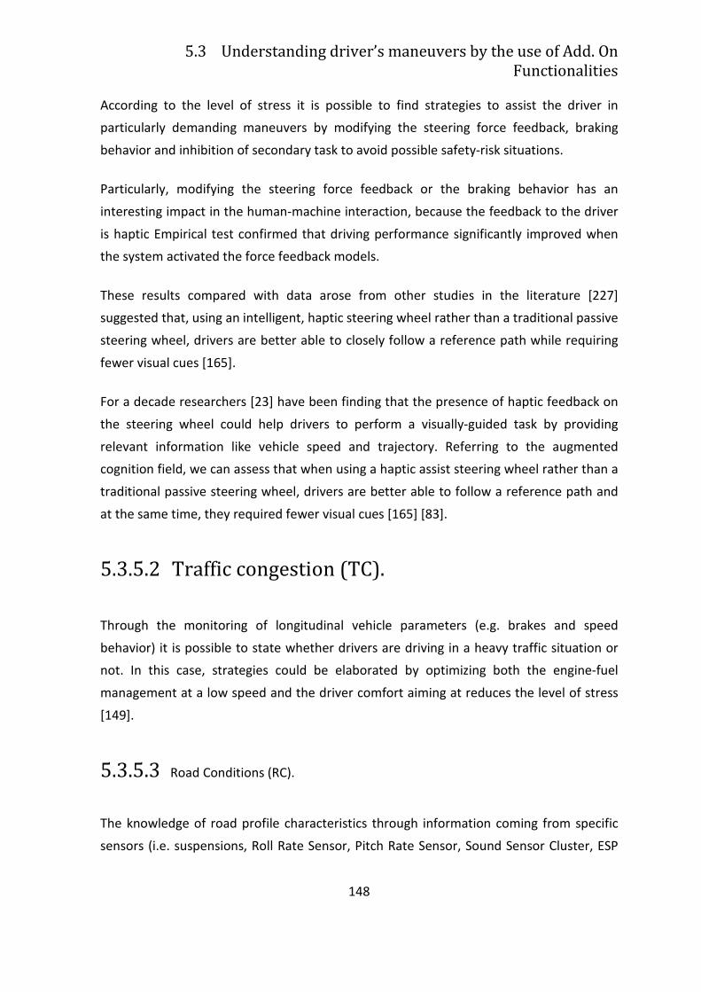
5.3 Understanding driver’s maneuvers by the use of Add. On
Functionalities
148
According to the level of stress it is possible to find strategies to assist the driver in
particularly demanding maneuvers by modifying the steering force feedback, braking
behavior and inhibition of secondary task to avoid possible safety-risk situations.
Particularly, modifying the steering force feedback or the braking behavior has an
interesting impact in the human-machine interaction, because the feedback to the driver
is haptic Empirical test confirmed that driving performance significantly improved when
the system activated the force feedback models.
These results compared with data arose from other studies in the literature [227]
suggested that, using an intelligent, haptic steering wheel rather than a traditional passive
steering wheel, drivers are better able to closely follow a reference path while requiring
fewer visual cues [165].
For a decade researchers [23] have been finding that the presence of haptic feedback on
the steering wheel could help drivers to perform a visually-guided task by providing
relevant information like vehicle speed and trajectory. Referring to the augmented
cognition field, we can assess that when using a haptic assist steering wheel rather than a
traditional passive steering wheel, drivers are better able to follow a reference path and
at the same time, they required fewer visual cues [165] [83].
5.3.5.2 Traffic congestion (TC).
Through the monitoring of longitudinal vehicle parameters (e.g. brakes and speed
behavior) it is possible to state whether drivers are driving in a heavy traffic situation or
not. In this case, strategies could be elaborated by optimizing both the engine-fuel
management at a low speed and the driver comfort aiming at reduces the level of stress
[149].
5.3.5.3 Road Conditions (RC).
The knowledge of road profile characteristics through information coming from specific
sensors (i.e. suspensions, Roll Rate Sensor, Pitch Rate Sensor, Sound Sensor Cluster, ESP
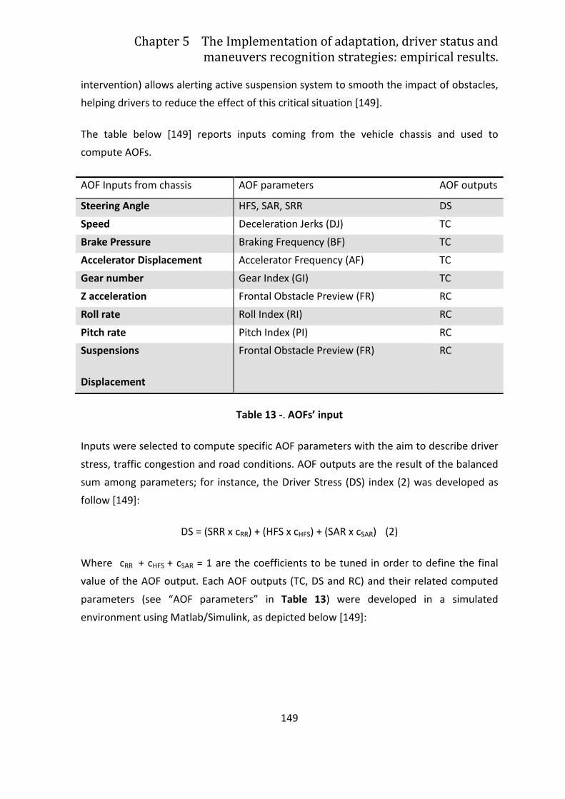
Chapter 5 The Implementation of adaptation, driver status and
maneuvers recognition strategies: empirical results.
149
intervention) allows alerting active suspension system to smooth the impact of obstacles,
helping drivers to reduce the effect of this critical situation [149].
The table below [149] reports inputs coming from the vehicle chassis and used to
compute AOFs.
AOF Inputs from chassis AOF parameters AOF outputs
Steering Angle HFS, SAR, SRR DS
Speed Deceleration Jerks (DJ) TC
Brake Pressure Braking Frequency (BF) TC
Accelerator Displacement Accelerator Frequency (AF) TC
Gear number Gear Index (GI) TC
Z acceleration Frontal Obstacle Preview (FR) RC
Roll rate Roll Index (RI) RC
Pitch rate Pitch Index (PI) RC
Suspensions
Displacement
Frontal Obstacle Preview (FR) RC
Table 13 -. AOFs’ input
Inputs were selected to compute specific AOF parameters with the aim to describe driver
stress, traffic congestion and road conditions. AOF outputs are the result of the balanced
sum among parameters; for instance, the Driver Stress (DS) index (2) was developed as
follow [149]:
DS = (SRR x cRR) + (HFS x cHFS) + (SAR x cSAR) (2)
Where cRR + cHFS + cSAR = 1 are the coefficients to be tuned in order to define the final
value of the AOF output. Each AOF outputs (TC, DS and RC) and their related computed
parameters (see “AOF parameters” in Table 13) were developed in a simulated
environment using Matlab/Simulink, as depicted below [149]:
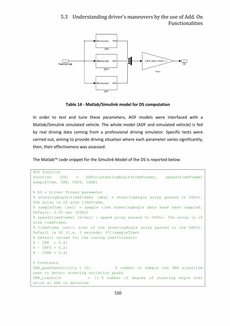
5.3 Understanding driver’s maneuvers by the use of Add. On
Functionalities
150
Table 14 - Matlab/Simulink model for DS computation
In order to test and tune these parameters, AOF models were interfaced with a
Matlab/Simulink simulated vehicle. The whole model (AOF and simulated vehicle) is fed
by real driving data coming from a professional driving simulator. Specific tests were
carried out, aiming to provide driving situation where each parameter varies significantly;
then, their effectiveness was assessed.
The Matlab™ code snippet for the Simulink Model of the DS is reported below.
%DS function function [DS] = DSFnc(steeringAngle(timeFrame), spe ed(timeFrame) sampleTime, CRR, CHFS, CSAR) % DS = Driver Stress parameter % steeringAngle(timeFrame) [deg] = steeringAngle ar ray passed to DSFnc. The array is of size timeFrame. % sampleTime [sec] = sample time steeringAngle data have been sampled. Default: 0.05 sec (20Hz) % speed(timeFrame) [m/sec] = speed array passed to DSFnc. The array is of size timeFrame. % timeFrame [sec]: size of the steeringAngle array passed to the DSFnc. Default is 60 (i.e. 3 seconds: 3*1/sampleTime) % Default values for the tuning coefficients: % - CRR = 0.4; % - CHFS = 0.2; % - CSAR = 0.4; % Constants SRR_peakSensitivity = 10; % number of sample the S RR algorithm uses to detect steering variation peaks SRR_treshold = 2; % number of degree of steering angle over which an SRR is detected
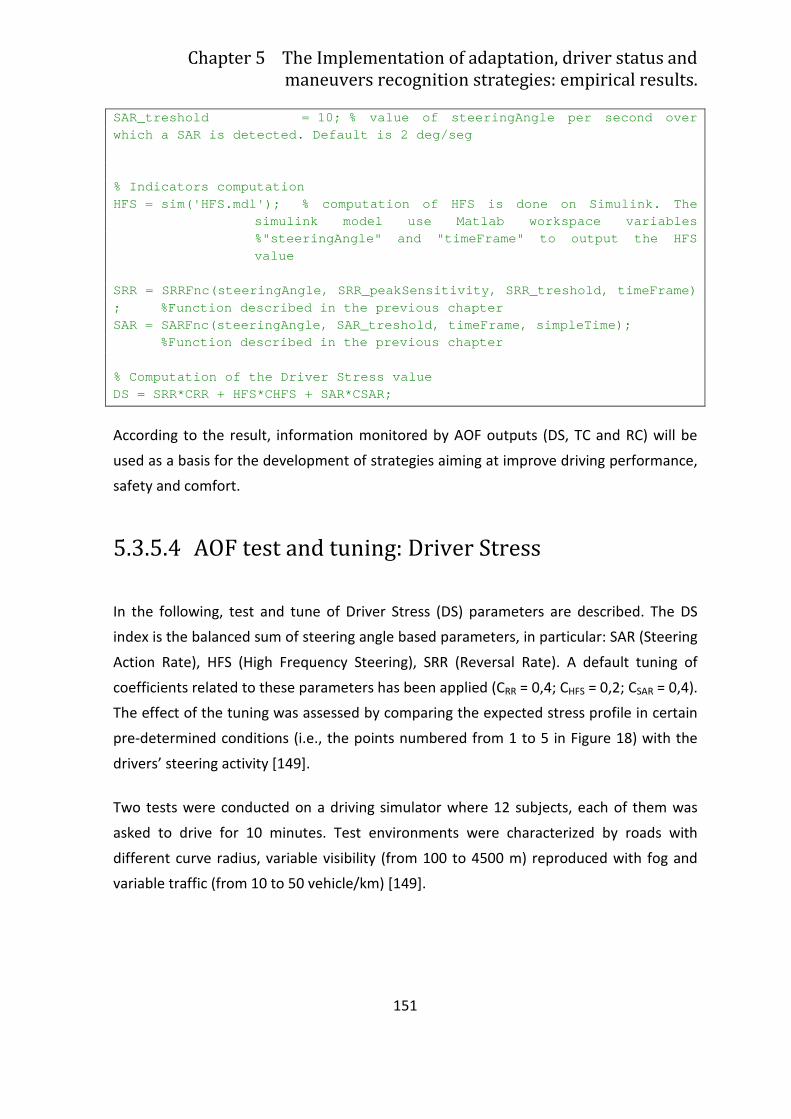
Chapter 5 The Implementation of adaptation, driver status and
maneuvers recognition strategies: empirical results.
151
SAR_treshold = 10; % value of steeringAngle per s econd over which a SAR is detected. Default is 2 deg/seg % Indicators computation HFS = sim('HFS.mdl'); % computation of HFS is done on Simulink. The
simulink model use Matlab workspace variables %"steeringAngle" and "timeFrame" to output the HFS value
SRR = SRRFnc(steeringAngle, SRR_peakSensitivity, SR R_treshold, timeFrame) ; %Function described in the previous chapter SAR = SARFnc(steeringAngle, SAR_treshold, timeFrame , simpleTime); %Function described in the previous chapter % Computation of the Driver Stress value DS = SRR*CRR + HFS*CHFS + SAR*CSAR;
According to the result, information monitored by AOF outputs (DS, TC and RC) will be
used as a basis for the development of strategies aiming at improve driving performance,
safety and comfort.
5.3.5.4 AOF test and tuning: Driver Stress
In the following, test and tune of Driver Stress (DS) parameters are described. The DS
index is the balanced sum of steering angle based parameters, in particular: SAR (Steering
Action Rate), HFS (High Frequency Steering), SRR (Reversal Rate). A default tuning of
coefficients related to these parameters has been applied (CRR = 0,4; CHFS = 0,2; CSAR = 0,4).
The effect of the tuning was assessed by comparing the expected stress profile in certain
pre-determined conditions (i.e., the points numbered from 1 to 5 in Figure 18) with the
drivers’ steering activity [149].
Two tests were conducted on a driving simulator where 12 subjects, each of them was
asked to drive for 10 minutes. Test environments were characterized by roads with
different curve radius, variable visibility (from 100 to 4500 m) reproduced with fog and
variable traffic (from 10 to 50 vehicle/km) [149].
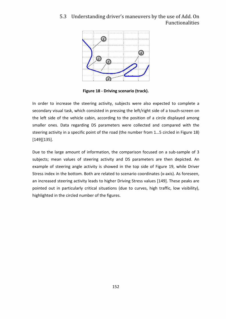
5.3 Understanding driver’s maneuvers by the use of Add. On
Functionalities
152
Figure 18 - Driving scenario (track).
In order to increase the steering activity, subjects were also expected to complete a
secondary visual task, which consisted in pressing the left/right side of a touch-screen on
the left side of the vehicle cabin, according to the position of a circle displayed among
smaller ones. Data regarding DS parameters were collected and compared with the
steering activity in a specific point of the road (the number from 1…5 circled in Figure 18)
[149][135].
Due to the large amount of information, the comparison focused on a sub-sample of 3
subjects; mean values of steering activity and DS parameters are then depicted. An
example of steering angle activity is showed in the top side of Figure 19, while Driver
Stress index in the bottom. Both are related to scenario coordinates (x-axis). As foreseen,
an increased steering activity leads to higher Driving Stress values [149]. These peaks are
pointed out in particularly critical situations (due to curves, high traffic, low visibility),
highlighted in the circled number of the figures.
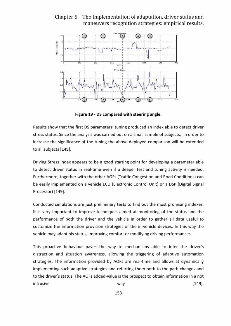
Chapter 5 The Implementation of adaptation, driver status and
maneuvers recognition strategies: empirical results.
153
Figure 19 - DS compared with steering angle.
Results show that the first DS parameters’ tuning produced an index able to detect driver
stress status. Since the analysis was carried out on a small sample of subjects, in order to
increase the significance of the tuning the above deployed comparison will be extended
to all subjects [149].
Driving Stress Index appears to be a good starting point for developing a parameter able
to detect driver status in real-time even if a deeper test and tuning activity is needed.
Furthermore, together with the other AOFs (Traffic Congestion and Road Conditions) can
be easily implemented on a vehicle ECU (Electronic Control Unit) or a DSP (Digital Signal
Processor) [149].
Conducted simulations are just preliminary tests to find out the most promising indexes.
It is very important to improve techniques aimed at monitoring of the status and the
performance of both the driver and the vehicle in order to gather all data useful to
customize the information provision strategies of the in-vehicle devices. In this way the
vehicle may adapt his status, improving comfort or modifying driving performances.
This proactive behaviour paves the way to mechanisms able to infer the driver’s
distraction and situation awareness, allowing the triggering of adaptive automation
strategies. The information provided by AOFs are real-time and allows at dynamically
implementing such adaptive strategies and referring them both to the path changes and
to the driver’s status. The AOFs added-value is the prospect to obtain information in a not
intrusive way [149].
154
Chapter 6
A Framework for Cognitive vehicles
supporting human-robot
interactions: the horse-rider
architecture of ADAS+
6.1 A cognitive driving assistance system
Based on the empirical results presented in the previous chapter (see Chapter 5), this
conclusive chapter aims at developing a little missing piece of the puzzle of the future
intelligent vehicles: namely to produce an architecture for a “cognitive driving assistance
system” which will substantially advance both integrated safety/assistance systems and
the cooperation between human beings and highly automated vehicles.
The history of intelligent transportation systems dates back to the late ‘80s [29] [195].
The initial focus on automation [226] shifted later to “intelligent vehicles” and driver
assistance systems [164] [96]. In fact, it was realized that intelligent vehicles must interact
with the driver. With today’s intelligent vehicles the driver is almost always in the loop
and the system provides assistance functions: from which the name of Advanced Driver
Assistance Systems, ADAS. Simple functions are already on the market (e.g., the Adaptive
Cruise Control).
Chapter 6 A Framework for Cognitive vehicles supporting human-robot
interactions: the horse-rider architecture of ADAS+
155
As we already discussed in previous chapter, ADAS systems are featured by three
elements: an adaptation strategy, a driver’s model able to assess driver’s status, a
maneuver model, able at recognizing driver’s maneuver.
But an ADAS system that really “understands the driver” by fitting driver behavior onto a
model of human-like motion alternatives, is something more that we can label ADAS+.
Such an artificial system, able to evaluate a number of possible alternative maneuvers
and to recognize which one is the driver choice, is up to know an ingredient of future
intelligent transportation systems. It will enable the full spectrum of applications that go
from integrated driver assistance in traditional vehicles, to smart human-robot
collaboration in automated vehicles, to automatic drive.
As we already argued in previous chapter (see paragraph 2.3.1.1), the metaphor of a rider
and a horse is used to explain how intelligent vehicles should interact with drivers. In this
metaphor the system is the ”brain” of the horse (limited to the domain of motion
planning), while applications are different modes in which the horse acts, as foreseen by a
cognitive architecture structure (for details see Chapter 4)
The importance of such a system is comparable with unified sensor fusion and
perception. In fact the system can be seen as a unified decision framework, which can be
used for different applications by designing the interaction module.
Although the proposal to build an artificial system that “thinks” compatible to the human
being is quite ambitious, this research issue is, to a great extent, built on proven
technologies as we discussed in Chapter 5 and thus its feasibility is largely assured.
Up to now, the evolution of intelligent vehicles is facing two bottlenecks: a) the
complexity of the real world environment that causes incomplete operation and b) the
complexity of the interactions with human beings.
Indeed, the topics of holistic continuous support and human interactions are still a matter
of research [95] [101] [105] [90] [72] [216] [18] [107] [3]. From the robotic perspective a
common trait of current research lines in intelligent vehicles, is that they focus on
systems that are carefully pre-programmed. On the other hand several researchers
formulated innovative visions and roadmaps concerning “smart collaboration” between

6.1 A cognitive driving assistance system
156
drivers and vehicles [95] [105] [101] [72] [3] [18] that need cognitive systems to be
effectively implemented. From the Cognitive Systems point of view, future intelligent
vehicles could be seen as robots that interact with human beings. The best kind of
interaction would occur if they were able to understand the driver goals and behave as
human peers.
157
6.2 From ADAS prediction system to ADAS+
symbiotic system
Peer-to-peer collaboration requires that the robot understands driver’s goals, where
“understands” means much more than simply “predict”, that is the typical strategy of
common ADAS. “Understanding” means that predictions of driver’s intention and
cognitive status togheter with driver’s inputs are mapped onto a co-driver independent
interpretation of the world. In the following paragraph how this concept is implemented
in a cognitive architecture will be explained.
The latest research challenge focus on the hypothesis that Cognitive Systems that
“understand” drivers could better cope with the complexity of the real interactions. The
interplay of two independent and peer units (man and robot) is expected to generate a
symbiotic system, which is the mean through which a new kind of collaboration between
drivers and vehicles, that has only been imagined in the Adaptive Automation domain,
can be brought to life, in what can be defined as ADAS+.
It is useful to briefly sum up the rider-horse metaphor or H-metaphor with the words of
Donald Norman [181] (for details see paragraph 2.3.1.1):
Think of skilled horseback riders. The rider “reads” the horse, just as the
horse can read its rider. Each conveys information to the other about
what is ahead. Horses communicate with their riders through body
language, gait, readiness to proceed, and their general behaviour: wary,
skittish, and edgy or eager, lively, and playful. In turn, riders
communicate with horses through their body language, the way they sit,
the pressures exerted by their knees, feet, and heels, and the signals
they communicate with their hands and reins. Riders also communicate
ease and mastery or discomfort and unease. This interaction is positive
example two. It is of special interest because it is an example of two
sentient systems, horse and rider, both intelligent, both interpreting the
world and communicating their interpretations to each other
(D. Norman, “The Design of Future Things”, MIT Press: 2007, p. 19).
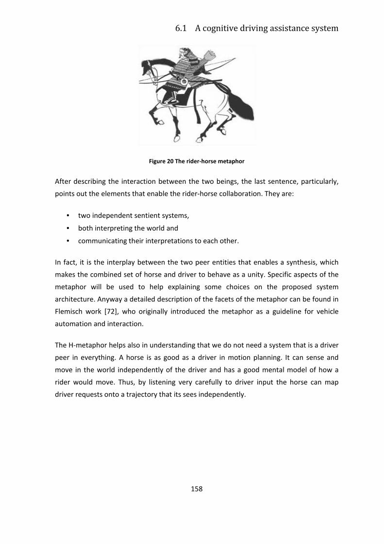
6.1 A cognitive driving assistance system
158
Figure 20 The rider-horse metaphor
After describing the interaction between the two beings, the last sentence, particularly,
points out the elements that enable the rider-horse collaboration. They are:
• two independent sentient systems,
• both interpreting the world and
• communicating their interpretations to each other.
In fact, it is the interplay between the two peer entities that enables a synthesis, which
makes the combined set of horse and driver to behave as a unity. Specific aspects of the
metaphor will be used to help explaining some choices on the proposed system
architecture. Anyway a detailed description of the facets of the metaphor can be found in
Flemisch work [72], who originally introduced the metaphor as a guideline for vehicle
automation and interaction.
The H-metaphor helps also in understanding that we do not need a system that is a driver
peer in everything. A horse is as good as a driver in motion planning. It can sense and
move in the world independently of the driver and has a good mental model of how a
rider would move. Thus, by listening very carefully to driver input the horse can map
driver requests onto a trajectory that its sees independently.
159
6.3 ADAS+ proposed architecture following
the H-metaphor
The high-level system architecture of a possible ADAS+ implementing the functionalities
that enable the peer-to-peer interactions is shown in Figure 21. This architecture has
been conceived taking inspiration from the H-metaphor. For readability and simplicity
reasons, Figure 21 omits a number of details, e.g., some feedback loops and the internal
structure of the blocks.
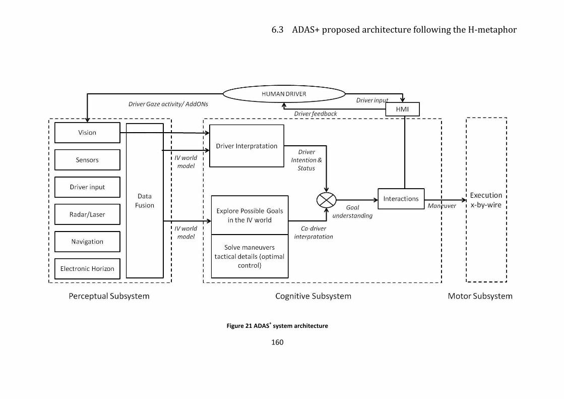
6.3 ADAS+ proposed architecture following the H-metaphor
160
Figure 21 ADAS+ system architecture
Chapter 6 A Framework for Cognitive vehicles supporting human-robot
interactions: the horse-rider architecture of ADAS+
161
Since the road scenario poses stringent safety-critical and time-critical requirements this
kind of architecture follows a pragmatic approach, that may allow a future
implementation of a complete H-metaphor that will combine Cognitive Systems
technology and hard-wired motion planning algorithms. Higher levels are cognitive but
the lower level of trajectory generation is based on optimal control, hence cognitive
systems are not used to learn minute vehicle control.
For motion planning it is possible to use very efficient methods developed by [3] [18] [37]
[143] [52] [245] [243] [51] [24] [25] [19] [20] [21] [63] [35] [22] which description is out of
the scope of this thesis work.
Beside the pragmatic motivation above, the use of such a hierarchical hybrid system,
where the higher levels are Cognitive but the lower ones are based on physics, has
another motivation, even stronger. In Fact, the H-metaphor requires the development of
a co-driver, who has to produce reference trajectories (the horse independent
interpretation of the world). Optimal control produces them as good or better as the
best-trained driver (making no mistake), with enough detail to be executable, physical
feasible, safe and optimized. This means that the co-driver is a very good reference
against which the driver behavior can be accurately evaluated. From the scientific point of
view, the proposed approach can be considered as an attempt to combine cognition with
control and dynamics of physical systems.
6.3.1 Perceptual Subsystem for the Environment
Assessment
According to the Model of Human Processor (see paragraph 4.1.1.1), the left block in
Figure 21 represents the perceptual subsystem that allows to identify the environment in
which the intelligent vehicles acts, namely the intelligent vehicle (IV) world model. The
output contains:
• the road network in front of the vehicle, with the list of all paths and sub paths
departing from the current position: this information is provided by an electronic
6.3 ADAS+ proposed architecture following the H-metaphor
162
horizon10
that derives it from enhanced digital maps (navigation) that contain the
details needed by the ADAS+ applications (e.g., slope, curvature, lane geometry,
traffic signs, etc.).
• objects with related properties: this information is provided by range sensors as
radar, laser scanner
• the vehicle itself position: this information is provided by fusing odometry,
inertial units, GPS and lane marking detection cameras data (vision).
The perceptual subsystem also detects the current driver input (steering and longitudinal
input)11.
6.3.2 Cognitive Subsystem for the Maneuver
Implementation .
Before getting the bottom of the matter, it is needed to better define some terms, in order
to avoid confusion.
• Driver intention & status: It is the output of the Driver Interpretation module
correlating driver gaze or Add-On fucntionalities data with the visual scene and
the IV world model: a symbolic indication of driver’s cognitive status and goal(s)
(without trajectory details). For example a driver may be attentive and might have
the intention to overtake
• Driver input. This is the longitudinal and lateral control imposed by the driver to
the vehicle. It corresponds to steering angle and pedal positions, but we can
summarise them with the longitudinal and lateral accelerations (or longitudinal
and lateral jerk). In some case it might be inconsistent with intentions (e.g., a
driver is not decelerating enough to negotiate properly a bifurcation).
10 A remark concerning the electronic horizon is that it is a form of “a priori” knowledge that can be
assimilated to memory. It stores the stationary part of the world, whereas range sensors and other sensors
detect the dynamic part of the world.
11 The current driver input (steering and longitudinal input) in the H-metaphor corresponds to rein tensions,
leg pressures and other signals that the rider uses to communicate with the horse [72].
Chapter 6 A Framework for Cognitive vehicles supporting human-robot
interactions: the horse-rider architecture of ADAS+
163
• Co-driver interpretation (of the world). It is a collection of all possible trajectories
that the codriver, as an independent system, sees in the IV world.
• Goal understanding: This is the process carried out by merging Driver Intention &
Status and Co-driver Interpratation, where namely driver intentions & status and
driver input are mapped onto the co-driver interpretation of the world. The result
is an executable manoeuvre (among those computed by the co-driver), which fits
the driver intention and/or the driver input.
Now it is possible to examine the cognitive subsystem of the ADAS+ architecture.
In the cognitive subsystem (see MHP discussed in paragraoh 4.1.1.1) two main cognitive
processes occurs: the first is the Co-driver (the horse) interpretation and the second is the
Driver Interpretation.
1. Co-driver Interpratation: this module represent the horse model. starting from
the sensed IV world model the co-driver explores the possible goals in the IV
worlds, solving tactical (physical level) maneuvers using optimal control strategies.
2. Driver Interpretation: this module represents the driver model. The driver status
(i.e. distraction, workload) and driver maneuver intention are sensed by the vision
module of the perceptual subsystem. The needed data are provided directly by
driver gaze activity data (using an eye-tracking system) or indirectly by Add-On
Functionalities (as discussed in paragraph 5.3).
The Co-driver interpretation is then merged with Driver Intention & Status in order to
plan a goal to be executed through proper maneuvers. The interaction module allows the
implementation of adaptive strategies based on:
• driver inputs (consequently to haptic, visual, acoustic or multimodal feedbacks
provided to the driver through the HMI): for mandatory safety issues, the driver
has the final authority on the overall driver-horse system [106], hence s/he must
be able to abort the maneuver undertaken by the system, changing the goal.
• the driver model: according to the interpretation of driver’s intention and overall
to the assessment of his/her status (i.e. distraction, as discussed in paragraph 5.2)
• the horse model: according to the sensed Driver Vehicle Environment status (for
details see paragraph 4.3).
164
Chapter 7
Conclusions
7.1 Final remarks
Nowadays, many efforts have been done and will be done to research and develop
partially or fully automated driver assistance systems, able to foresee an accident and to apply a mitigation strategy, as for example the headway distance or lane keeping control
The aim of these system is to support drivers, especially in risky and critical situations, or
whenever distraction may occur, since driver distraction is a contributing factor in up of 23% of crashes [207].
Driving is an interaction between the driver and the vehicle and it can be considered a
holistic driver-vehcile cooperative system [72]. From these basic idea a lot of studies on
cognitive vehicle supporting the concept of human-robot interaction have been carried
out. The vision of a vehicle intelligent like an horse, able to create a symbiotic system with
the driver (the horse-rider paradigm) has the aim of making system smarter, more efficient and able to support the driver when s/he really needs.
Accordingly, developing effective techniques for developing proper adaptation strategies,
for detecting driver status or wrong behavior (i.e. driver mental workload or distraction),
driver’s intention (meant as maneuver recognition) are essential to achieve the aforementioned aim.
The first step for the design of a cognitive vehicle able to assess the driver status and
intentions is the development a model able to explain and reproduce driver’s characteristics.
In this context, the work carried out in this thesis consisted in investigating the feasibility
of a cognitive architecture for the development of a behavioural ADAS, named ADAS+,
Chapter 7 Conclusions
165
that brings together the driver model, the horse or co-pilot model, and an adaptation strategies derived form the interactions between the driver and the horse.
The feasibility of such an architecture has been investigated analyzing:
• The problem of foreseeing the next accident
• Risk mitigation strategies for the accident avoiding
• Adaptive automation strategies
• Causes and effects of driving distraction
• Distraction modeling techniques (i.e. Machine Learning)
• Soundness of the integration of the driver model into a cognitive architecture
Furthermore the feasibility of a framework for cognitive vehicle has been investigated
through empirical testing on a driving simulator of the effectiveness of each ADAS+
component:
1 The adaptation strategy implemented into a Context Dependent Steering Wheel
2 The driver’s model implemented by Adaptive Neuro Fuzzy Inference System and
Neural Network 3 The maneuver recognition implemented by Add-On functionalities.
At the best of our knowledge, the approach proposed in this thesis is a quite a new one
on the topics of architecture for cognitive vehicles and ADAS systems, despite of the wide literature about this issue.
In fact, all approaches for the ADAS design doesn’t face the contemporary integration of
the adaptation strategies, the driver model and the maneuver recognition in order to develop a system able to act as a co-driver.
.
166
7.2 Future works
The limit of this thesis work actually opens possibilities for future works and investigations on cognitive vehicles supporting human robot interaction.
In fact a lot of work should be done to develop an ADAS+ system (i.e. an implementation of the rider-horse metaphor) and to empirically test it.
Considering that horse and rider operate as an holistic entity during locomotion, future
cognitive cars will provide seamless and continuous driver support, just as a horse that, capable of autonomous control, continuously adapts to rider’s intentions.
The level of seamless support ranges from full autonomous driving to the precise execution of driver commands.
Of course, this metaphor provides a continuous spectrum of control, where the signals
(and their strength) that are passed between the rider and the horse are dependant upon both context and the correct interpretation of the rider intentions by the horse.
The developing of a “co-driver” that, just like a horse, will be able to “understand” the
driver, requires that it connects messages received from the driver with its own interpretation of the world (as a peer).
To achieve this aim, a possible way is the use of efficient real-time optimal control for the
low level functions of the robots (motion planning).
A flexible Artificial Cognitive System will be instead responsible for understanding the driver and producing appropriate interactions and support.
Nowadays engineered solutions cannot cope with all eventualities of symbiotic
locomotion in road scenarios, and the task is too complex for learning systems alone. It is
only through the integration of cognition and control that a viable solution to the problem can be reached.
For these reasons, neither the Intelligent Vehicle domain nor the Cognitive System
domain can provide a solution in isolation. But by bringing these two research areas
together, there is the possibility to develop cognitive cars as a future and fesible mass-market products.
Chapter 8 References
167
Chapter 8
References
[1]. AC/DC Technical Annex ver.0.99. Sixth Framework Programme (http://www.acdc-
project.org).
[2]. Adomavicius G., Tuzhilin A. (2005). “Toward the Next Generation of Recommender
Systems: A Survey of the State-of-the-Art and Possible Extensions”, IEEE
Transactions on Knowledge and Data Engineering 17 (6) 2005, 734-749
[3]. Amditis A., Bertolazzi E., Bimpas M., Biral F., Da Lio M., Danielsson L., Lind H.,
Saroldi A., Sjogren A. (2009). “A Holistic Approach to the Integration of Safety
Applications: the INSAFES Subproject within the European Framework Program 6
Integrated Project PReVENT,” in IEEE trans. on Intelligent Transportation Systems,
special issue on ITS and Road Safety, Digital Object Identifier
10.1109/TITS.2009.2036736.
[4]. An, P.E. and Harris, C.J. (1996). “An intelligent driver warning system for vehicle
collision avoidance”, IEEE Transactions on Systems, Man and Cybernetics, Part A:
Systems and Humans, Vol. 26, No. 2, pp.254±261.
[5]. Anderson, P. (1999). “Complexity theory and organization science”. Organization
Science, 10: 216–232.
[6]. Anderson, J. R., & Lebiere, C. (1998). The atomic components of thought. Mahwah,
NJ: Lawrence Erlbaum.
[7]. Andreone L., Amditis A., Deregibus E., Damiani S., Morreale D., and Bellotti F.
(2005). "Beyond Context-Awareness: Driver-Vehicle-Environment Adaptively.
168
From the COMUNICAR Project to the AIDE Concept." Proc. IFAC 16th World
Congress.
[8]. Angell, L., Young, R., Hankey, J., & Dingus, T. (2002). “An evaluation of alternative
methods for assessing driver workload in the early development of in-vehicle
information systems”. In SAE Proceedings, 2002-01-1981, May
[9]. Ardissono L., Console L., and Torre I. (2001). “An adaptive sys- tem for the
personalized access to news”. AI Commun., 14(3):129–147
[10]. Baddeley A. D. (1986). Working Memory, Oxford University Press, 978-
0198521167, USA
[11]. Bajçinca N., Cortesão R., Hauschild M., (2005). “Robust Control for Steer-by-Wire
Vehicles”, Autonomous Robots, 19, no. 2, Sept. 2005, pp. 193 – 214.
[12]. Baldi, P. and Brunak S. (2001). Bioinformatics: The Machine Learning Approach,
2nd edition ed. MIT Press.
[13]. Baldwin, C. L., & Coyne, J. T. (2003). “Mental Workload as a Function of Traffic
Density: Comparison of Physiological, Behavioural, and Subjective Indices”. Paper
presented at the Driving Assessment 2003, Utah, USA
[14]. Basacik D., Stevens A. (2008). Scoping Study of Driver Distraction, Road Safety
Research Report No. 95, Transport Research Laboratory, October 2008,
Department for Transport: London
[15]. Basu, C., Hirsh, H., and W. Cohen (1998). “Recommendation as Classification:
Using Social and Content-Based Information in Recommendation”. Fifteenth
National Conference in Artificial Intelligence, Madison, Wisconsin, MW.
[16]. Berghout, L., Versteegt, E., van Arem, B. (2003). Advanced driver assistance
systems; Results of the State of the Art of ADASE-II, available on www.adase2.net.
[17]. Bertacchini, P. Pavan, L. Tamagnini, L. Fergnani (2005) “Control of brushless motor
with hybrid redundancy for force feedback in steer-by-wire applications”, IECON
2005 - 32nd Annual Conference of IEEE, Raleigh North Carolina USA, 6-10 Nov.
2005, pp. 1407-1412
Chapter 8 References
169
[18]. Bertolazzi E., Biral F., Da Lio M., Saroldi A., Tango F. (2009). “Supporting Drivers in
Keeping Safe Speed and Safe Distance: the SASPENCE Subproject within the
European Framework Program 6 Integrated Project PReVENT,” in IEEE trans. on
Intelligent Transportation Systems, special issue on ITS and Road Safety, Digital
Object Identifier 10.1109/TITS.2009.2035925
[19]. Bertolazzi E., Biral F., Da Lio M. (2005). “Symbolic–Numeric Indirect Method for
Solving Optimal Control Problems for Large Multibody Systems – The Time-
Optimal Racing Vehicle Example,” Multibody System Dynamics, vol. 13-2, March
2005, pp. 233-252.
[20]. Bertolazzi E., Biral F., Da Lio M. (2006). “Symbolic-numeric efficient solution of
optimal control problems for multibody systems,” Journal of Computational and
Applied Mathematics, vol. 185-2, January 2006, pp. 404-421.
[21]. Bertolazzi E., Biral F., Da Lio M. (2007). “Real-time motion planning for multibody
systems,”, Multibody System Dynamics, vol. 17-2-3, April 2007, pp. 119-139.
[22]. Bertozzi M., Broggi A., Fascioli A. (2006). “VisLab and the Evolution of Vision-Based
UGVs, Published by the IEEE Computer Society, vol. 39, no. 12, pp. 31-38,
December 2006, DOI 10.1109/MC.2006.448.
[23]. Bertollini GP, Hogan RM (1999). “Applying Driving Simulation to Quantify Steering
Effort Preference as a Function of Vehicle Speed”. Society of Automobile
Engineers, 1999-01-0394
[24]. Betts J.T., (1998). “Survey of numerical methods for trajectory optimization,” J.
Guid. Control Dyn., vol. 21-2, pp. 193-207.
[25]. Biegler L., Cervantes A.M., Wachter A. (2002). “Advances in simultaneous
strategies for dynamic process optimization,” Chem. Eng. Sci., vol. 57-4, pp. 575–
593.
[26]. Billings, C. E. (1991). Human-centered aircraft automation: A concept and
guidelines (NASA Tech. Memo. No.103885), Moffet Field, CA: NASA Ames
Research Center
[27]. Billings, C. E. (1997). Aviation Automation: The Search for a Human-Centered
Approach, Lawrence Erlbaum Associates, 978-0805821260, USA
170
[28]. Billings, C.E., & Woods, D.D. (1994). “Concerns about adaptive automation in
aviation systems”. In M. Mouloua & R. Parasuraman (Eds.), Human performance in
automated systems: current research and trends (pp. 264-269). Hillsdale, NJ:
Erlbaum.
[29]. Bishop, R. (2005 ). “Intelligent vehicle R&D: A review and contrast of programs
worldwide and emerging trends”, Annals of Telecommunications, 60, 3-4, 228-263.
[30]. Bovair, S., Kieras, D. E., & Polson, P. G. (1990). “The acquisition and performance
of textediting skill: A cognitive complexity analysis”. Human-Computer Interaction,
5(1), 1-48.
[31]. Byrne, M. D. (2003). “Cognitive architecture”. In J. Jacko & A. Sears (Eds.), The
human-computer interaction handbook. Fundamentals, evolving technologies and
emerging applications (pp. 97–117). Mahwah, NJ: Erlbaum
[32]. Bloedorn, E., Mani, I. and MacMillan T. R. (1996). “Machine Learning of User
Profiles: Representational Issues”. Thirteen National Conference on Artificial
Intelligence, Portland, Oregon, 433-438.
[33]. Boer, E. R., Hildreth, E. C., & Goodrich, M. A. (1998). “A driver model of attention
management and task scheduling: Satisficing decision making with dynamic
mental models”. In Proceedings of the 17th European Annual Conference on
Human Decision Making and Manual Control.
[34]. Boer, E. R., & Hoedemaeker, M. (1998). “Modeling driver behavior with different
degrees of automation: A hierarchical decision framework of interacting mental
models”. In Proceedings of the 17th European Annual Conference on Human
Decision Making and Manual Control.
[35]. Braid D., Broggi A., Schmiedel G. (2006). “The TerraMax Autonomous Vehicle” J.
Field Robotics, vol. 23, no. 9, pp. 693–708.
[36]. Broadbent, D. E. (1958). Perception and Communication, Pergamon Press, ISBN
not available, U.K
[37]. Bruce J., Veloso M. (2002). “Real-time randomized path planning for robot
navigation,”. In: Proceedings of the IEEE-RSJ Intelligent Robots and Systems, pp.
2383–2388.
Chapter 8 References
171
[38]. Brusilovsky, P. (2002). Adaptive hypermedia, User Modeling and User Adapted
Interaction, Ten Year Anniversary Issue (Alfred Kobsa, ed.) 11 (1/2), 2002, 87-110
[39]. Brusilovsky, P., and E. Schwarz (1997). “User as Student: Towards an Adaptive
Interface for Advanced Web Applications”. Sixth International Conference on User
Modelling, 177-188.
[40]. Cacciabue P.C. (1998). Modelling and Simulation of Human Behaviour in System
Control, Springer-Verlag, London, UK.
[41]. Cacciabue P.C. (2007). Modelling Driver Behaviour in Automotive Environments.
Cacciabue, P.Carlo (Ed.), pp. 105-120.
[42]. Calefato C., Montanari R., Tango, F. (2007). “Advanced Drivers Assistant Systems in
automation”, in Proceedings of HCI International 2007, 12th International
Conference on Human-Computer Interaction, 22-27 July 2007, Beijing (China).
[43]. Calefato C., Montanari R., Tesauri F. (2008). “The Adaptive Automation Design”
(book chapter), in Advances in Human-Computer Interaction, ISBN 978-3-902613-
38-7, I-Tech Education and Publishing KG; Vienna, Austria.
[44]. Campbell, J. L., Carney, C., & Kantowitz, B. H. (1998). Human factors design
guidelines for advanced traveler information systems (ATIS) and commercial
vehicle operations (CVO) (FHWA-RD-98-057). Washington, DC: Federal Highway
Administration. Available online at
http://www.fhwa.dot.gov/tfhrc/safety/pubs/atis/, consulted on 4th October 2010.
[45]. Card, S.K; Moran, T. P; and Newell, A. (1986). “The Model Human Processor: An
Engineering Model of Human Performance”. In K. R. Boff, L. Kaufman, & J. P.
Thomas (Eds.), Handbook of Perception and Human Performance. Vol. 2: Cognitive
Processes and Performance, pages 1–35.
[46]. Cardillo, D., Calefato, C., Minin, L., & Montanari, R. (2009). “A Workload Manager
Architecture for the Monitoring of Drivers’ Cognitive Impairment”, In the
Proceedings of the CHI Italy June, (Vol. IxD&A - Interaction Design &
Architecture(s), Design for the Future Experience, pp. 70-76), 17-19, 2009, Rome.
[47]. CARE European Road Accident Database (2010). National Statistical Reports. It can
be accessed through the Europa server
172
(http://ec.europa.eu/transport/road_safety/pdf/observatory/trends_figures.pdf),
consulted on the 10th August 2010
[48]. CARE European Road Accident Database (2010). National Statistical Reports. It can
be accessed through the Europa server
(http://ec.europa.eu/transport/road_safety/pdf/gis/mapcare10_fatal_2008.pdf),
consulted on the 10th August 2010
[49]. Catino M. (2002). Da Chernobyl a Linate. Incidenti tecnologici o errori
organizzativi? Carocci editore, Roma
[50]. Cena, F., Console, L., Gena, C., Goy, A., Levi, G., Modeo, S., Torre, I. (2006).
“Integrating Heterogeneous Adaptation Techniques to Build a Flexible and Usable
Mobile TouristGuide AICommunication”, The European Journal on Artificial
Intelligence, 19(4) 369-384, pp 369-384 ISSN: 0921-7126
[51]. Cervantes A.M., Biegler L. (2001). “Optimization strategies for dynamic systems,”
in Encyclopedia of Optimization, vol. 4, pp. 216–227. Kluwer, Norwell, MA.
[52]. Cerven W.T., Bullo F., Coverstone V.L. (2004). “Vehicle motion planning with time-
varying constraints,” J. Guid. Control Dyn., vol. 27-3, pp. 506–509.
[53]. Chai, Y. (2004). A Study of Effect of Steering Gain And Steering Torque on Driver’s
Feeling For SBW Vehicle, Proceedings of Fisita world automotive congress.
Barcelona.
[54]. Chapman, P. R., & Underwood, G. (1998). “Visual search of dynamic scenes: Event
types and the role of experience in viewing driving situations”. In G. Underwood &
et al. [Eds.], Eye guidance in reading and scene perception [pp. 369-393]. Oxford,
England UK: Anonima Romana
[55]. Chin, D.N.: (1989) KNOME: modelling what the user knows. In: A. Kobsa and W.
Wahlster (eds.): User models in dialog systems. Berlin: Springer-Verlag, 74-107.
[56]. Chiu, S. (1994). “Fuzzy Model Identification Based on Cluster Estimation”. Journal
of Intelligent & Fuzzy Systems, Vol. 2, No. 3, Sept. 1994.
[57]. Choi, D., Konik, T., Nejati, N., Park, C., & Langley, P. (2007).“ A believable agent for
first-person shooter games”. In Proceedings of the third annual artificial
Chapter 8 References
173
intelligence and interactive digital entertainment conference (pp. 71–73). Stanford,
CA: AAAI Press.
[58]. Clark, A. (2003). Natural-Born Cyborgs: Minds, Technologies and the Future of
Human Intelligence, Oxford University Press, USA
[59]. Commission of the European Communities (2000). Recommendation on safe and
efficient in-vehicle information and communication systems: a European statement
of principles on human machine interface. OJ L19, January 25
[60]. Console L., Torre I., Lombardi I., Gioria S. and Surano V., “Personalized and
adaptive services on board a car – an application for tourist information”, Journal
of Intelligent Information Systems 21(2) (2003), 249–284.
[61]. Cook RI, O'Connor MF (2005). “Thinking about accidents and systems”. In:
Manasse HR, Thompson KK, eds. Medication safety: A guide for healthcare
facilities. Bethesda, MD: American Society of Health Systems Pharmacists; p. 73-
88.
[62]. Cooper, P. J., & Zheng, Y. (2002). Turning gap acceptance decision-making: impact
of driver distraction. Journal of Safety Research, 33, 321-335.
[63]. Cossalter V., Da Lio M., Lot R., and Fabbri L. (1999). “A general method for the
evaluation of vehicle maneuverability with special emphasis on motorcy- cles,”
Veh. Syst. Dyn., vol. 31, pp. 113–135.
[64]. Dacko L., Darlington R., Shindman D. (1990). “Landing gear steer-by-wire control
system; digital vs. analog study”, Proceedings of the Reliability and Maintainability
Symposium, Los Angeles CA, 23-25 Jan. 1990, pp.215–220.
[65]. De Waard, D. (1996). The measurement of drivers' mental workload. PhD thesis,
University of Groningen. Haren, The Netherlands: University of Groningen, Traffic
Research Centre.
[66]. Dingus, T.A., Antin, J.F., Hulse, M.C., and Wierwille, W.W. (1989). Attentional
Demand Requirements of an Automobile Moving-Map Navigation System,
Transportation Research , 23A (4), 301-315.
174
[67]. Donmez, B., Boyle, L. N., & Lee, J. D. (2006a). “Drivers' attitudes toward imperfect
distraction mitigation strategies”. Transportation Research Part F: Traffic
Psychology, 9(6), 387-398
[68]. Ehmanns, D., Spannheimer, H. Roadmap, available on www.adase2. net
[69]. Endsley, Mica. R. (1996). “Automation and situation awareness”, in Parasuraman
R. e Mouloua M. (Eds), Automation and human performance: Theory and
applications (pp. 163-181), Manwah, NJ: Lawrence Erlbaum.
[70]. EU energy and transport in figures, Statistical Pocketbook (2009). European
Communities, Belgium. It can be accessed through the Europa server
(http://europa.eu).
[71]. Farber, E., Foley, J., & Scott, S. (2000). Visual attention design limits for ITS in-
vehicle systems: The Society of Automotive Engineers standard for limiting visual
distraction while driving. Transportation Research Board Annual General Meeting,
Washington DC
[72]. Flemisch F., Adams C., Conway S., Goodrich K., Palmer M., and Schutte P., (2003).
The HMetaphor as Guideline for Vehicle Automation and Interaction, (NASA/TM—
2003-212672). Hampton, VA: NASA Langley Research Center.
[73]. Fong T., Thorpe C., Baur C. (2001). “Collaboration, Dialogue, and Human-Robot
Interaction”. 10th
International Symposium of Robotics Research, November,
Lorne, Victoria, Australia.
[74]. Forbes J., Huang T., Kanazawa K., and Russell S.J. (1995). “The BATmobile: Towards
a Bayesian automated taxi”. In Proc. IJCAI, pages 1878{1885, 1995.
[75]. Gena C. and Torre I. (2004). “The importance of adaptivity to provide on-board
services. A preliminary evaluation of an adaptive tourist information service on
board vehicles special issue on Mobile”, A.I, Applied Artificial Intelligence Journal.
[76]. Godley, S. T., Triggs, T. J., & Fildes, B. N. (2001). “Driving simulator validation for
speed research”. Accident Analysis and Prevention, 34, 589-600.
Chapter 8 References
175
[77]. Goodman, M. J., Bents, F. D., Tijerina, L., Wierwille, W., Lerner, N., & Benel, D.
(1997). An investigation of the safety implications of wireless communication in
vehicles. Department of Transportation, NHTSA, Washington, DC.
[78]. Gray, W. D., Young, R. M., & Kirschenbaum, S. S. (1997). “Introduction to this
special issue on cognitive architectures and human-computer interaction”.
Human-Computer Interaction, 12, 301-309.
[79]. Green, P. (2000). “Crashes Induced by Driver Information Systems and What Can
be Done to Reduce Them” (SAE Paper 2000-01-C008). In Convergence 2000 (pp.
26–36). SAE Publication.
[80]. Green, P. (2004). Driver distraction, telematics design and workload managers:
safety issues and solutions (SAE Paper No. 2004-21-0022). Warrendale, PA: Society
of Automotive Engineers.
[81]. Green, P., Hoekstra, E., & Williams, M. (1993). Further on-the-road tests of driver
interfaces: examination of a route guidance system and car phone. Report No.
UMTRI-93-35. University of Michigan Transportation Research Institute, Ann
Arbor, MI.
[82]. Green, P., Levison, W., Paelke, G., & Serafin, C. (1993). Preliminary human factors
design guidelines for driver information systems (Report FHWA-RD-94-087).
Washington, DC: Federal Highway Administration
[83]. Griffiths, P., & Gillespie, R. (2004). “Shared Control between Human and Machine:
Haptic Display of Automation during Manual Control of Vehicle Heading”, 12th
International Symposium on Haptic Interfaces for Virtual Environment and
Teleoperator Systems (pp. 358-366). Chicago, IL, USA.
[84]. Green P., Gillespie T., Reifeis S., Wei-Hass L., Ottens O., Subjective evaluation of
steering effort levels, Technical Report UMTRI-84-39, 1984.
[85]. Gulian, E., Matthews, G., Glendon, A. I., Davies, D. R., & Debney, L. M. (1989a).
“Dimensions of driver stress”, Ergonomics, 32, 585-602.
[86]. Haigney, D., & Westerman, S. J. (2001). “Mobile phone use and driving: a critical
review of research methodology”. Ergonomics, 44, 132-143.
176
[87]. Hancock, P.A., & Chignell, M.H. (1987). “Adaptive control in human-machine
systems”. In P.A. Hancock (Ed.), Human factors psychology (pp. 305-345). North
Holland: Elsevier Science Publishers
[88]. Harbluk, J. L., Noy, Y. I., Eizenman, M. (2002). The impact of cognitive distraction
on driver visual behaviour and vehicle control, TP No. 13889 E. Transport Canada,
Canada
[89]. Harrison, M. D., Johnson, P. D., Wright, P. C. (2002). “Automating Function in multi
agent control systems: supporting the decision process”, Proceedings of the Tenth
Safety-critical Systems Symposium.
[90]. HAVEit – Highly automated vehicles for intelligent transport, http://www.haveit-
eu.org/
[91]. Hayama R., Nishizaki K., Nakano S., Katou K. (2000). “The vehicle stability control
responsibility improvement using steer-by-wire”, Proceedings of the Intelligent
Vehicles Symposium, Dearborn MI USA, 3-5 Oct.2000, pp. 596 – 601.
[92]. Haykin S. (1999). Neural networks: a comprehensive foundation. Englewood Cliffs,
NJ: Prentice Hall
[93]. Hebb D.O. (2002 ). “The Organisation of Behaviour”; Lawrence Erlbaum Associates
Inc, (new edition).
[94]. Hedlund, J., Simpson, H.M. & Mayhew, D.R. (2006). International Conference on
Distracted Driving – Summary of Proceedings and Recommendations. Paper
presented at the International Conference on Distracted Driving, Toronto, in
October 2–5, 2005.
[95]. Heide, K. Henning (2006). “The ‘‘cognitive car’’: A roadmap for research issues in
the automotive sector,” Annual Reviews in Control, vol. 30, pp. 197–203.
[96]. Hellaker J. (1990). “PROMETHEUS: Strategy,” in Proc. Veh. Electron. 90’s: Int.
Congr. Transp. Electron. (Convergence), Dearborn, MI, Oct. 1990, pp. 195–199.
SAE publication 901139.
Chapter 8 References
177
[97]. Hessburg, T. and Tomizuka, M. (1993). “Fuzzy logic control for lateral vehicle
guidance”, Proceedings of the IEEE Conference on Control Applications, Vol. 2,
pp.581±586.
[98]. Hilburn, B., Molloy, R., Wong, D., & Parasuraman, R. (1993). “Operator versus
computer control of adaptive automation”. In R. S. Jensen & D. Neumeister (eds.),
Proceedings of the 7th International Symposium on Aviation Psychology (pp. 161-
166). Columbus, OH: Department of Aviation, The Ohio State University
[99]. Hilburn, B., Jorna, P., Byrne, E., & Parasuraman, R. (1997). “The effect of adaptive
air traffic control (ATC) decision aiding on controller mental workload”. In M.
Mouloua & J. Koonce (Eds.), Human automation interaction, 84–91. Mahwah, NJ:
Erlbaum.
[100]. Hill W., Stead L., Rosenstein M., and Furnas G. (1995). “Recommending and
Evaluating Choices in a Virtual Community of Use,” Proc. Conf. Human Factors in
Computing Systems.
[101]. Hoch S., Schweigert M., Althoff F., Rigoll G. (2007). “The BMW SURF Project: A
Contribution to the Research on Cognitive Vehicles,” in Proc. 2007 IEEE Intelligent
Vehicles Symposium, Istanbul, Turkey, June 3-15, 2007.
[102]. Hollands, J. & Wickens, C. (1999). Engineering Psychology and Human
Performance. Englewood Cliffs, NJ, Prentice-Hall
[103]. Hong K.S., Sohn H.C., Hedrick J.K. (2002). “Modified skyhook control of semi-active
suspensions: a new model, gain scheduling, and hardware-in-the-loop tuning”,
Journal of Dynamic Systems, Measurement, and Control 124, pp. 158–167.
[104]. Hwan Jang J., Tong-Jin P., Chang-Soo H. (2003). “A control of vehicle using steer-
by-wire system with hardware-in-the-loop-simulation system”, Proceedings of the
Advanced Intelligent Mechatronics conference, Kobe Japan, 20-24 July 2003,
Volume 1, pp. 389 – 394.
[105]. Inagaki, T. (2008). “Smart collaboration between humans and machines based on
mutual understanding,” Annual Reviews in Control, vol.32, pp. 253–261, 2008.
[106]. Inagaky, T., (2003). “Automation and the cost of authority”. International Journal
of Industrial Ergonomics, Vol. 31, 169-174.
178
[107]. INSAFES – INtegrated SAFEty Systems, http://www.prevent-ip.org/insafes/
[108]. JAMA (2004). Guidelines for in-vehicle display systems – Version 3.0, available at:
http://www.jama-english.jp/release/release/2005/In-
vehicle_Display_GuidelineVer3.pdf, consulted on 4th October 2010
[109]. Jeha R., HeeSoo K. (1999). “Virtual environment for developing electronic power
steering and steer-by-wire systems” Proceedings of the International Conference
on Intelligent Robots and Systems, Kyongju South Korea, 17-21 Oct. 1999, pp.
1374 – 1379.
[110]. Jenness, J. W., Lattanzio, R. J., O’Toole, M., & Taylor, N. (2002). “Voice-activated
dialing or eating a cheeseburger: Which is more distracting during simulated
driving?” Proceedings of the Human Factors and Ergonomics Society 46th Annual
Meeting, Pittsburgh, PA.
[111]. Ji, Q., Yang, X. (2002). “Real-time eye, gaze, and face pose tracking for monitoring
driver vigilance”. Real-Time Imaging (8), 1077–2014
[112]. Jokela M. (2006). Implementation and Analysis of the Cockpit Activity Assessment
Module; Master of Science Thesis.
[113]. Jones, R. M., Laird, J. E., Nielsen, P. E., Coulter, K. J., Kenny, P., & Koss, F. V. (1999).
“Automated intelligent pilots for combat flight simulation”. AI Magazine, 20(1),
27-41.
[114]. Jyh-Shing Roger Jang (1993). “ANFIS: Adaptive-Network-Based Fuzzy Inference
System”. IEEE Transactions on Systems, Man and Cybernetics, 23 (3): 665- 685.
[115]. Kaber, D. B., & Endsley, M. (2004). “The effects of level of automation and
adaptive automation on human performance, situation awareness and workload
in a dynamic control task”. Theoretical Issues in Ergonomics Science, 5, 113–153.
[116]. Kaber D. B. (1997). The Effect of Level of Automation and Adaptive Automation on
Performance in Dynamic Control Environments (Tech. Work. Doc.: ANRCP-NG-
ITWD-97-01). Amarillo, TX: Amarillo National Resource Center for Plutonium.
[117]. Kaber, D., Prinzel III, L., Wright, M., Clamann, M., (2002). Workload-Matched
Adaptive Automation. Support of Air Traffic Controller Information Processing
Stages. Tech. Report NASA/TP-2002-211932, NASA.
Chapter 8 References
179
[118]. Kaber, D. B. and Riley, J. (1999). “Adaptive automation of a dynamic control task
based on secondary task workload measurement”. International Journal of
Cognitive Ergonomics, Vol. 3, No. 3, 169-187.
[119]. Kaber, D. B., Riley, J. M., Tan, K., Endsley, M. R, (2001). “On the Design of Adaptive
Automation for Complex Systems”, International Journal of Cognitive Ergonomics,
Vol. 5(1), Lawrence Erlbaum Associates, Inc.
[120]. Kay M., (2006). “Adaptive automation accelerates process development”,
Bioprocess international 4(4):70-78.
[121]. Kieras, D. E., Meyer, D. E., Mueller, S., & Seymour, T. (1999). “Insights into working
memory from the perspective of the EPIC architecture for modeling skilled
perceptual-motor and cognitive human performance”. In A. Miyake & P. Shah
(Eds.), Models of working memory: Mechanisms of active maintenance and
executive control (pp. 183-223). New York: Cambridge University Press.
[122]. Kimura, S. (2005). “Research on Steering Wheel Control Strategy as Man-Machine
Interface for Steer-by-Wire System”, Proceedings of FISITA world automotive
congress (pp. 29-33). Barcelona, Spain.
[123]. Kintsch, W. (1998). Comprehension: A paradigm for cognition. New York:
Cambridge University Press.
[124]. Kircher, K. (2007). Driver distraction: A review of the literature (VTI rapport R594A)
Linköping: VTI.
[125]. Kirwan, B. and, L. K. Ainsworth (1992). Guide to task analysis. Taylor and Francis,
London
[126]. Kitajima, M., & Polson, P. G. (1997). “A comprehension-based model of
exploration”. Human-Computer Interaction, 12(4), 345-389.
[127]. Kitajima, M., Blackmon, M. H., & Polson, P. G. (2000). “A comprehension-based
model of web navigation and its application to web usability analysis”. In S.
McDonald & Y. Waern & G. Cockton (Eds.), People and Computers XIV - Usability or
Else! (Proceedings of HCI 2000) (pp. 357-373). New York: Springer.
180
[128]. Klauer SG, Dingus TA, Neale VL, et al. (2006). The impact of driver inattention on
near-crash/crash risk: an analysis using the 100 car naturalistic driving study data.
Washington: National Highway Traffic Safety Administration, DOT HS 810 594-
April, Virginia tech Transportation Institute, Blacksburg, VA.
[129]. Kobsa A., Koenemann J., and Pohl W. (2001). “Personalised hypermedia
presentation techniques for improving online customer relationships”. Knowl. Eng.
Rev., 16(2):111–155, 2001.
[130]. Koedinger, K. R., Anderson, J. R., Hadley, W. H., & Mark, M. (1997).”Intelligent
tutoring goes to school in the big city”. International Journal of Artificial
Intelligence in Education, 8, 30–43.
[131]. Kornhauser, A.L. (1991). “Neural network approaches for lateral control of
autonomous highway vehicles”, VNIS '91 Vehicle Navigation and Information
Systems Conference.
[132]. Kraiss K. F. (1995). “Implementation of user-adaptive assistants with neural
operator models,” Control Eng. Practice, Vol.3, No.2, pp. 249–256.
[133]. Kutila M. (2006). Methods for Machine Vision Based Driver Monitoring
Applications; PhD Thesis, VTT Pubblications, 2006
[134]. Kutila M., et al. (2005). “Online Detection of Driver Distraction. Preliminary Results
from the AIDE Project”; Proceedings of the 2005 International Truck and Bus Safety
and Security Symposium. Washington, Alexandria, Virginia, U.S.A. 14.16 Nov 2005.
Pp. 86.96
[135]. Kutila M., et al. (2006). “Driver Cognitive Distraction Detection: Feature Estimation
and Implementation”; Submitted to Proceedings of the Institution of Mechanical
Engineers, Part D: Journal of Automobile Engineering on 11 Apr 2006. United
Kingdom. ISSN: 0954-4070
[136]. Landauer, T. K., & Dumais, S. T. (1997). “A solution to Plato's problem: The latent
semantic analysis theory of acquisition, induction, and representation of
knowledge”. Psychological Review, 104(2), 211-240.
[137]. Langley, P. (1995). Elements of Machine Learning. San Francisco: Morgan
Kaufmann
Chapter 8 References
181
[138]. Langley P. (1999). “User Modeling in Adaptive Interfaces”. In Kay J., editor,
Proceedings of the Seventh Internation Conference on User Modeling, pages 357
371. Springer 1999.
[139]. Langley, P., & Choi, D. (2006a). “A unified cognitive architecture for physical
agents”. In Proceedings of the twenty-first AAAI conference on artificial
intelligence. Boston: AAAI Press.
[140]. Langley, P., & Choi, D. (2006b). “Learning recursive control programs from
problem solving”. Journal of Machine Learning Research, 7, 493–518.
[141]. Langley, P., Cummings, K., & Shapiro, D. (2004). “Hierarchical skills and cognitive
architectures”. In Proceedings of the twenty-sixth annual conference of the
cognitive science society (pp. 779–784). Chicago, IL.
[142]. Langley P., Laird J. E., Rogers S. (2009). “Cognitive architectures: Research issues
and challenges”, Cognitive Systems Research Volume 10, Issue 2, June 2009, Pages
141-160 CA, 2002.
[143]. LaValle S.M., Kuffner J.J. (2001), “Randomized kinodynamic planning,” Int. J.
Robot. Res., vol.20-5, pp. 378–400.
[144]. Layton, C., Smith, P.J. and McCoy, C.E. (1994). “Design of a Cooperative Problem-
Solving System for En-Route Flight Planning: An Empirical Evaluation”. Human
Factors, 36:94--119.
[145]. Lee J. et al (2004). Safety VEhicles using adaptive Interface Technology (Task 5
Final Report: Phase 1 of the SAVE-IT project). [Referred 25 Oct 2006]. Available at:
www.volpe.dot.gov/opsad/saveit
[146]. Lee, J.D & Strayer, D.L. (2004). “Preface to the special section on driver
distraction”. Human Factors, 46(4), 583-586.
[147]. Liang Y. et al. (2007). “Real-time Detection of Driver Cognitive Distraction using
Support Vector Machines”; IEEE Transaction on Intelligent Transportation Systems,
Vol.8, No.2, June 2007
182
[148]. Lin, Y., Tang, P., Zhang, W. J., and Yu, Q. (2005). “Artificial Neural Network
Modeling on Driver Handling Behavior in the Driver-Vehicle-Environment System”,
International Journal of Vehicle Design, Vol. 37, Issue 1, pp. 24-45
[149]. Lolli F., Marzani S., Minin L., Montanari R., Calefato C. (2009). “Not-invasive add-on
functionalities for the realtime assessment of driver-vehicle interaction”, in
Proceedings of VI Conference of the Italian Chapter of AIS, Achieving Fusion in the
Interconnected World: Exploring the connection between organizations and
technology, Costa Smeralda (Italy), October 2-3, 2009
[150]. MacAdam, C.C. and Johnson, G.E. (1996). “Application of elementary neural
networks and preview sensors for representing driver steering control behavior”,
Vehicle System Dynamics, Vol. 25, pp.3±30.
[151]. Martens M.H. & van Winsum, W. (20009. Measuring distraction: the Peripheral
Detection Task, Internal Report. TNO Human Factors, Soesterberg, The
Netherlands.
[152]. Marzani S., Tesauri F., Minin L., Calefato C. (2009). “Designing a control and
visualization system for offhighway machinery according to the Adaptive
Automation paradigm”, in Proceedings of HCI International 2009, 9-24 July 09, San
Diego, CA, USA
[153]. Malin, J. T., & Schreckenghost, D.L. (1992). Making intelligent systems team
players: Overview for designers. NASA Technical Memorandum 104751, Johnson
Space Center, Houston, TX.
[154]. Mattes, S. (2003). “The lane change task as a tool for driver distraction
evaluation”. In H. Strasser, H. Rausch & H. Bubb (Eds.), Quality of work and
products in enterprises of the future (pp. 57-60). Stuttgart: Ergonomia Verlag.
[155]. Mayser C., Piechulla W., Weiss K.E., König W. (2003). “Driver workload
monitoring”, Proceedings of the 50th-Anniversary Conference of the GfA and the
XVII Annual ISOES, Munich, Allemagne, Mai 2003, p. 41-44.
[156]. McDonald, W. A., & Hoffman, E. R. (1980). “Review of relationships between
steering wheel reversal rate and driving task demand”. Human Factors 22, 733-
739.
Chapter 8 References
183
[157]. McLean, J.R. & Hoffman, E.R. (1975). “Steering wheel reversals as a measure of
driver performance and steering task difficulty”. Human Factors 17,248-256.
[158]. Mectron – Laboratorio di Meccatronica http://www.intermech.unimore.it/on-
line/Home/MECTRON.html, consulted on the 11th Agust 2010
[159]. Meyer, D. E., & Kieras, D. E. (1997). “A computational theory of executive cognitive
processes and multiple-task performance: I. Basic mechanisms”. Psychological
Review, 104(1), 3- 65.
[160]. Michalski R. S., Bratko I. and Kubat M. (1998). Machine Learning and Data Mining,
R. S. Michalski, I. Bratko, and M. Kubat, Eds. New York: Wiley.
[161]. Michon, J.A. (1985). “A critical review of driver behaviour models: What do we
know? what should we do?” In L.A Evans and R.C. Schwing (Eds.) Human
Behaviour AND Traffic Safety. (pp. 487-525). New York: Plenum Press.
[162]. Miller, C., Funk, H., Wu, P., Goldman, R., Meisner, J., Chapman, M. (2005). „The
Playbook Approach to Adaptive Automation”, In Proceedings of the Human
Factors and Ergonomics Society's 49th Annual Meeting, Orlando, FL (USA)
[163]. Miller, C.; Funk, H.; Wu, P.; Goldman, R.; Meisner, et Wu, P. (2005).“ Implications
of adaptive vs. adaptable uis on decision making : Why ‘automated adaptiveness’
is not always the right answer”. In Proceedings of the 1st International Conference
on Augmented Cognition, Las Vegas, NV.
[164]. Mimuro T., Miichi Y., Maemura T., Hayafune K. (1996). “Functions and devices of
Mitsubishi active safety ASV,” in Proc. of the 1996 IEEE Intelligent Vehicle
Symposium, Tokyo, pp. 248-253, 10.1109/IVS.1996.566386
[165]. Minin L., Marzani S., Tesauri F., Montanari R., Calefato C. (2009). "Context-
dependent force-feedback steering wheel to enhance drivers’ on-road
performances”, in Proceedings of HCI International 2009, 9-24 July 09, San
Diego, CA, USA
[166]. Minin L., Montanari R., Corbelli C., Iani C. (2008). “Force Feedback: new frontier as
the innovative driving comfort tool”, in Proceedings of the Computer Human
Interaction conference (CHI), Florence, Italy.
184
[167]. Mitchell T.M.; (1997). Machine Learning, Mc-Graw Hill International Editions
[168]. Moray, N., Inagaki, T., & Itoh, M. (2000). “Situation adaptive automation, trust and
self-confidence in fault management of time-critical tasks”. Journal of
Experimental Psychology: Applied, Vol. 6, 44–58.
[169]. Mourant R.R., Sadhu P. (2002). “Evaluation of Force Feedback Steering in a Fixed
Based Driving Simulator”, Human Factors and Ergonomics Society 46 th Annual
Meeting.
[170]. Montanari R., Minin L. (2008). Efficacy tests of the Ergonomic Steer-ByWire
System, Mectron Deliverable 5.3, Mectron Italian regional project, PRRIITT - 3.4 –
Action A, Emilia Romagna Region.
[171]. Mussone, L., Reitani, G. and Rinelli, S. (1995). “An ANN model to study driver
behavior in urban environment”, 10th International Conference on the
Applications of Artificial Intelligence in Engineering, pp.419±426.
[172]. Nakazawa S., Ishihara T., Inooka H. (2003). “Real-time algorithms for estimating
jerk signals from noisy acceleration data”, Int.l J. of Applied Electromagnetics and
Mechanics, 18, 1-3, pp. 149-163.
[173]. Neale V. L., Dingus T. A., Klauer S. G., Suweeks J., Goodman M. (2006). An overview
of the 100-car naturalistic study and findings, Paper Number 05-0400, National
Highway Traffic Safety Administrationin,Washington D.C.
[174]. Neisser U. ((1967). Cognitive Psychology. Appleton-Century-Crofts, New York
[175]. Neusser, S. (1993). “Neural control for lateral vehicle guidance”, IEEE Micro,
pp.57±66. 2, pp.1143±1145.
[176]. Newell, A. (1990). Unified theories of cognition. Cambridge, MA: Harvard
University Press.
[177]. Newell A., Simon H. (1972). Human Problem Solving; Prentice-Hall, Englewood
Cliffs, N.Y.
[178]. NHTSA. (2000b). Internet Forum on Driver Distraction. Available at
www.nrd.nhtsa.dot..gov/departments/nrd-13/driver-distraction/welcome.htm

Chapter 8 References
185
[179]. Nilsson, N. (1996). Introduction to Machine Learning. Stanford University, available
at: http://ai.stanford.edu/~nilsson/MLBOOK.pdf, consulted on 4th October 2010
[180]. Norman, D. (1989). The problem of automation: Inappropriate feedback and
interaction not overautomation (ICS Report 8904). La Jolla, CA: Institute for
Cognitive Science, U. C. San Diego.
[181]. Norman, D. (2007). The Design of Future Things, Basic Books, New York, NY.
[182]. Oliver, N. and Pentland, A. P. (2000). “Graphical Models for Driver Behavior
Recognition in a SmartCar”, MIT IEEE intelligent vehicles symposium.
[183]. Olsson, S., & Burns, P. C. (2000). Measuring distraction with a peripheral detection
task. On-line paper. Available at www.nrd.nhtsa.dot..gov/departments/nrd-
13/driver-distraction/welcome.htm.
[184]. Östlund, J. et al. (2004). HASTE Deliverable 1 - Human Machine Interface And the
Safety of Traffic in Europe, Project GRD1/2000/25361.
[185]. Östlund, J., Nilsson, L., Carsten, O., Merat, N., Jamson, H., Jamson, S., et al. (2004).
Deliverable 2 - HMI and Safety-Related Driver Performance (No. GRD1/2000/25361
S12.319626): Human Machine Interface And the Safety of Traffic in Europe
(HASTE) Project.
[186]. Papatheodorou C. (2001). “Machine Learning in User Modeling”. Lecture Notes in
Computer Science, Vol. 2049:pages 286–294, September 2001
[187]. Parasuraman, R., Bahri, T., Deaton, J., Morrison, J., & Barnes, M. (1992). Theory
and design of adaptive automation in aviation systems (Progress Rep. No.
NAWCADWAR-92033-60) Warmister, PA: Naval Air Warfare Center, Aircraft
Division, Factors, 30.
[188]. Parasuraman, R., Mouloua, M., Molloy, R., & Hilburn, B. (1993). “Adaptive function
allocation reduces performance costs of static automation”. In R. S. Jensen & D.
Neumeister (eds.), Proceedings of the 7th International Symposium on Aviation
Psychology
186
[189]. Parasuraman, R., Mouloua, M., & Molloy, R. (1996). “Effects of adaptive task
allocation on monitoring of automated systems”. Human Factors, Vol. 38 (4), 665-
679.
[190]. Parasuraman, R., Mouloua, M., & Hilburn, B. (1999). “Adaptive aiding and adaptive
task allocation enhance human-machine interaction”. In M. W. Scerbo & M.
Mouloua (Eds.), Automation technology and human performance: Current
research and trends (pp. 119–123). Mahwah, NJ: Erlbaum.
[191]. Parasuraman, R., Sheridan, T., & Wickens, C. D. (2000). “A model for types and
levels of human interaction with automation”. IEEE Transactions on Systems, Man
and Cybernetics—Part A: Systems and Humans, 30(3), 286–297.
[192]. Parsons, H.M. (1985). “Automation and the individual: Comprehensive and
comparative views”. Human Factors, Vol. 27, 99-112.
[193]. Pentland A. and Liu A. (1995). “Modeling and predicition of human behavior”. In
IEEE Intelligent Vehicles 95, September 1995
[194]. Perry SJ, Wears RL, Cook RI (2005). “The role of automation in complex system
failures”. J Patient Safety; 1: 56-61.
[195]. Piao J., Mcdonald M. (2008). “Advanced Driver Assistance Systems from
autonomous to cooperative approach”, Transport Reviews, 28-5, 659-684.
[196]. Polk, T. A., & Newell, A. (1995). “Deduction as verbal reasoning”. Psychological
Review, 102(3), 533-566.
[197]. Prinzel, Lawrence J. (2003). Team-Centerede perspective for Adaptive Automation
Design, Langley Research Center, Hampton, Virginia, available from NASA Center
for Areospace Information (CASI).
[198]. Prinzel, L., Freeman, F., Scerbo, M., Mikulka, P., & Pope, A. (2003). “Effects of a
psychophysiological system for adaptive automation on performance, workload
and event-related potential P300 component”. Human Factors, Vol. 45, 601–614.
[199]. Priyandoko, G., Mailah, M., Jamaluddin, H. (2008). “Vehicle Active Suspension
System Using Skyhook Adaptive Neuro Active Force Control”, Mechanical Systems
and Signal Processing, doi:10.1016/j.ymssp.2008.07.014
Chapter 8 References
187
[200]. Rahimi, M., Briggs, R.P., and Thom, D.R. (1990). “A field evaluation of driver eye
and head movement strategies toward environmental targets and distracters”.
Applied Ergonomics, 21(4), 267-275
[201]. Ranney, T.A., Garrott, W.R. & Goodman, M.J. (2001). “NHTSA driver distraction
research: past, present and future”. Paper presented at the 17th International
Technical Conference on Enhanced Safety of Vehicles, Amsterdam.
[202]. Raskutti, B. and A. Beitz (1996). „Acquiring User Preferences for Information
Filtering in Interactive Multi-Media Services”. Pacific Rim International Conference
on Artificial Intelligence, 47-58.
[203]. Recarte, M. A., & Nunes, L. M. (2000). “Effects of verbal and spatial-imagery task
on eye fixations while driving”. Journal of Experimental Psychology: Applied, 6, 31–
43.
[204]. Reed, S. K. (1996). Cognition: Theory and applications (4th ed.). Pacific Grove, CA:
Brooks/Cole Publishing.
[205]. Reed, M. P., & Green, P. A. (1999). C”omparison of driving performance on-road
and in low-cost simulator using a concurrent telephone dialling task.” Ergonomics,
42, 1015-1037.
[206]. Regan, M. (2007). “Driver distraction: Reflections on the past, present and future”.
In: I.J. Faulks, M. Regan, M. Stevenson, J. Brown, A. Porter & J.D. Irwin (Eds.).
Distracted driving. Sydney, NSW: Australasian College of Road Safety. Pages 29-73.
[207]. Regan M. A, Lee J. D., Young K. L. (2009). Driver Distraction. Theory, Effects, and
Mitigation, CRC Press, Taylor & Francis Group, New York.
[208]. Resnick P., Iakovou N., Sushak M., Bergstrom P., and Riedl J. (1994 ). “GroupLens:
An Open Architecture for Collaborative Filtering of Netnews,” Proc. 1994
Computer Supported Cooperative Work Conf.
[209]. Resnick, P. and Varian H.R. (1997). “Recommender Systems”. Communications of
the ACM 4(3), 56-58
188
[210]. Ritter, F. E., & Young, R. M. (2001). “Embodied models as simulated users:
Introduction to this special issue on using cognitive models to improve interface
design”. International Journal of Human-Computer Studies, 55, 1-14.
[211]. Rouse, W.B. (1976). “Adaptive allocation of decision making responsibility
between supervisor and computer”. In T.B. Sheridan & G. Johannsen (Eds.),
Monitoring behavior and supervisory control, 295-306. New York: Plenum Press.
[212]. Rouse, W. B. (1988). “Adaptive aiding for human/computer control”, in Human
Factors, Vol. 30, 431-438.
[213]. Saade, J. J and Diab, H. B. (2000). “Defuzzification Techniques for Fuzzy
Controllers”, IEEE Trans. Syst., Man, Cybern., vol. 30, Feb. 2000, pp. 223-229.
[214]. Salvucci, D. D., Boer, E. R., & Liu, A. (2001). “Toward an integrated model of driver
behavior in a cognitive architecture”. Transportation Research Record, 1779, 9 –
16.
[215]. Salvucci, D. and Liu A. (2002). “The Time Course of a Lane Change: Driver Control
and Eye Movement Behavior”. Transportation Research, Part F, 5(2): 123-132.
[216]. SASPENCE – SAfe SPEed Safe distaNCE, http://www.prevent-ip.org/saspence/
[217]. Scallen, S., Hancock, P. A., & Duley, J. A. (1995). “Pilot performance and preference
for short cycles of automation in adaptive function allocation”. Applied
Ergonomics, Vol. 26, 397-403.
[218]. Scerbo, M.W., (1996). “Theoretical perspectives on adaptive automation”. In R.
Parasuraman & M. Mouloua (Eds.), Automation and human performance: Theory
and applications, 37-63. Mahwah, NJ: Erlbaum
[219]. Segawa M., Nakano S., Nishihara O. (2001). “Vehicle stability control strategy for
steer by wire system”, JSAE Review, 22, no. 4, pp. 383-388.
[220]. Shardanand U. and Maes P. (1995). “Social Information Filtering: Algorithms for
Automating ‘Word of Mouth’” Proc. Conf. Human Factors in Computing Systems.
[221]. Sheridan, T. B. (1997). “Supervisory control”. In G. Salvendy (ed.), Handbook of
human factors (pp. 1295-1327). New York: John Wiley & Sons.
Chapter 8 References
189
[222]. Shepanski, J.F. and Macy, S.A. (1987). “Manual training techniques of autonomous
systems based on artificial neural networks”, IEEE 1st International Conference on
Neural Networks, pp.21±24.
[223]. Sheridan, T. (2002). Humans and automation: System design and research issues.
New York: Wiley.
[224]. Sheridan, T.B. (1992) Telerobotics, Automation, and Human Supervisory Control.
MIT Press, Cambridge, MA.
[225]. Sheridan, T. B., & Parasuraman, R. (2006). “Human-automation interaction.
Reviews of Human Factors and Ergonomics”, 1, 89–129.
[226]. Shladover S. E. (2007). “PATH at 20—History and Major Milestones,” IEEE trans. on
Intelligent Transportation Systems, vol. 8, no. 4, pp. 584-592, December 2007.
[227]. Steele, M., & Gillespie, B. (2001). “Shared control between human and machine:
Using a haptic steering wheel to aid in land vehicle guidance”, Proceedings of the
Human Factors and Ergonomics Society 45th annual meeting (pp. 1671– 1675).
Minneapolis, Minnesota, USA.
[228]. Stutts, J. (2005). “How risky is distracted driving? What crash data reveals”. Paper
presented at the International Conference on Distracted Driving, Toronto,October
2005.
[229]. Stutts, J. C., Feaganes, J., Rodgman, E., Hamlett, C., Meadows, T., Reinfurt, D.,
Gish, K., Mercadante, M., & Staplin, L. (2003). Distractions in everyday driving.
Report prepared for AAA Foundation for Traffic Safety, Washington, DC.
[230]. Stutts, J.C., Reinfurt, D.W., Staplin, L. & Rodgman, E.A. (2001). The role of driver
distraction in traffic crashes (Report prepared for AAA Foundation for Traffic
Safety). Washington, DC.
[231]. Sugeno, M. (1985). Industrial applications of fuzzy control, Elsevier Science Pub.
Co.
[232]. Tan, P. N. (2005). Introduction to Data Mining. Pearson Addison Wesley, Boston.
190
[233]. Tango, F., (2009). Modelling Driver’s Behaviour by means of Machine Learning
techniques in a Driver-Vehicle-Environment (DVE) Framework, PhD Thesis,
University of Turin, Department of Computer Science.
[234]. Tango F. and Botta M. (2009). “Evaluation of Distraction in a Driver-Vehicle-
Environment Framework: An Application of Different Data-Mining Techniques”,
Lecture Notes in Computer Science, Volume 5633, Advances in Data Mining.
Applications and Theoretical Aspects, Pages 176-190
[235]. Tango F., Calefato C., Minin L., Canovi L. (2009). “Moving attention from the road:
a new methodology for the driver distraction evaluation using machine learning
approaches”, Proceedings of the 2nd conference on Human System Interactions,
May 21-23, Catania, Italy
[236]. Tango F., Minin L., Tesauri F., Montanari R. (2010). “Field tests and machine
learning approaches for refining algorithms and, correlations of driver’s model
parameters”, Applied Ergonomics Volume 41, Issue 2, March 2010, Pages 211-224
[237]. Tasca, L. (2005). “Driver distraction: towards a working definition”. Paper
presented at the International Conference on Distracted Driving, 2005-10-3,
Toronto, Ontario, Canada.
[238]. Tijerina L., Kiger S., Rockwell T., Wierwille W. (1995). Heavy Vehicle Driver
Workload Assessment-Task 5: Workload Assessment Protocol, NHTSA Report DOT
HS 808 467(5), Washington DC, June 1995.
[239]. Toffin D., Reymond G., Kemeny A., Droulez J. (2003). “Influence of steering wheel
torque feedback in a dynamic driving simulator”. Proceedings of the Driving
Simulation Conference, Dearborn MI North America, 8-10 Oct., 2003.
[240]. Trafton, J. G., Cassimatis, N. L., Bugajska, M., Brock, D., Mintz, F., & Schultz, A.
(2005). “Enabling effective human–robot interaction using perspective-taking in
robots”. IEEE Transactions on Systems, Man and Cybernetics, 25, 460–470.
[241]. Triggs, T. J. (1996). “Driving simulation for railway crossing research”. Paper
prepared for the Seventh International Symposium on Railroad-Highway Grade
Crossing Research and Safety – Getting Active at Passive Crossings, Monash
University, Clayton, Australia.
Chapter 8 References
191
[242]. van Winsum, W., Martens, M., & Herland, L. (1999). The effect of speech versus
tactile driver support messages on workload, driver behaviour and user
acceptance. TNO-report TM-99-C043. Soesterberg, Netherlands.
[243]. Veeraklaew T., Agrawal S.K., “New computational framework for trajectory
optimization of highorder dynamic systems”, J. Guid. Control Dyn., vol. 24-2, 2001,
pp. 228–236.
[244]. Verwey, W.B. (1991). Towards Guidelines for in-car Information Management:
Driver Workload in Specific Situations. Technical Report IZF 1991 C-13,
Soesterberg, The Netherlands: TNO Institute of Perception.
[245]. von Stryk O., Bulirsch R. (1992). “Direct and indirect methods for trajectory
optimization,” Ann. Oper. Res., vol. 37-1–4, 1992, pp. 357–373.
[246]. Waltz E. L. (1998). “Information understanding: integrating data fusion and data
mining processes”; In Proceedings of the 1998 IEEE International Symposium on
Circuits and Systems. Monterey, CA.
[247]. Wiener, E.L. (1989). Human factors of advanced technology ('glass cockpit')
transport aircraft. Technical report 117528. Moffett Field, CA: NASA Ames
Research Center.
[248]. Wilson, J. (2005). “Legislation and regulation in Canada with respect to drover
distraction”. Paper presented at the International Conference on Distracted
Driving, Toronto, Canada, October 2-5, 2005
[249]. Wilwert C., Song Y., Simonot -Lion F., Clément T. (2003). “Evaluating quality of
service and behavioral reliability of steer-by-wire systems” Proceedings of the
Emerging Technologies and Factory Automation conference, 16-19 Sept. 2003,
IEEE Conference Volume 1, pp. 193- 200.
[250]. Yih P., Jihan R., Gerdes J. (2005) “Modification of vehicle handling characteristics
via steer-by-wire”, IEEE transactions on control systems technology, 13, no. 6, pp.
965-976.
[251]. Young, K. & Regan, M. (2007). “Driver distraction: A review of the literature”. In:
I.J. Faulks, M. Regan, M. Stevenson, J. Brown, A. Porter & J.D. Irwin (Eds.).
Distracted driving. Sydney, NSW: Australasian College of Road Safety.

192
[252]. Young, K., Regan, M. & Hammer, M. (2003). Driver distraction: a review of the
literature, Monash University Accident Research Centre, Report No. 206, available
at: http://www.monash.edu.au/muarc/reports/muarc206.pdf
[253]. Zhang Y.; Owechko, Y.; Zhang J. (2004). “Driver cognitive workload estimation: a
data-driven perspective”, in Proceedings of the 7th International IEEE Conference
on Intelligent Transportation Systems, ITSC 3-6 Oct. 2004, Washington DC.
[254]. Zheng B., Altemare C., Anwar S. (2005). “Fault Tolerant Steer-By-Wire Road Wheel
Control System”, Proceedings of the American Control Conference, Portland
Oregon, 8-10 June, pp. 1619-1624.


![Lucia 2008[Tesi dottorato-full]R06_low.pdf](https://img.pdfslide.tips/doc/110x75/5866862d1a28abe83f8b65fa/lucia-2008tesi-dottorato-fullr06lowpdf.jpg)