Embed Size (px)
Citation preview
Saudi Electricity Company الشركة السعودية للكهرباء
SEC Distribution Materials Specifications
56-SDMS-05 Rev 0
DATE: 29-01-2013G
TWO TRAILER MOUNTED MOBILE SUBSTATIONS, 33/13.8KV
Prepared By: Technical Support Department of Distribution Services Sector
Saudi Electricity Company هرباءالشركة السعودية للك
SEC Distribution Materials Specifications
56-SDMS-05 Rev 0
DATE: 29-01-2013G
Page 2 of 43
APPROVALS
Saudi Electricity Company هرباءالشركة السعودية للك
SEC Distribution Materials Specifications
56-SDMS-05 Rev 0
DATE: 29-01-2013G
Page 3 of 43
TABLE OF CONTENTS
1.0 INTRODUCTION
2.0 CROSS REFERENCES
3.0 APPLICABLE CODES AND STANDARDS
4.0 BASIC REQUIREMENTS AND GUIDELINES
5.0 SCOPE OF SUPPLY
6.0 REQUIREMENTS OF MAJOR MATERIALS AND EQUIPMENT
7.0 TESTS
8.0 TECHNICAL DATA SCHEDULES
9.0 SCHEDULE OF SCOPE OF WORK
10.0 CTS REQUIREMENT DETAILS (REFEREED TO ATTACHED SLD)
11.0 LIST OF DOCUMENTS AND SCHEDULES TO BE SUBMITTED
12.0 SINGLE LINE DIAGRAM (SLD)
13.0 PILOT TERMINATION, ISOLATION AND SUPERVISION BOX WITH 5KV
INSULATION
Saudi Electricity Company هرباءالشركة السعودية للك
SEC Distribution Materials Specifications
56-SDMS-05 Rev 0
DATE: 29-01-2013G
Page 4 of 43
1.0 INTRODUCTION
The proposed Mobile Substations of 20MVA is to provide alternative source of supply to customrs temporarily, in case of loss of regular supply due to damage/fault occurring to network equipments. Hence, the design and supply of Mobile Substation shall cover/match and suit all the possible conditions, with easy free mobility. The following are the expected cases:
Failure of incoming supply either from Overhead Line or Underground Cable to 33/13.8kV System of Substations.
Failure of 33/13.8kV Power Transformers.
Failure of 33kV and or 13.8kV Switchgears. The other utilization is to relieve overloaded substations or conection of rental generation to 33KV
network thru this mobile substation. The Mobile Substation shall have facilities to suit the above conditions.
2.0 CROSS REFERENCES
This Material Standard Specification shall be read in conjunction with the latest revision of
SEC General Specification No.01-SDMS-01, titled "General Requirements for All
Equipment/ Materials" which shall be considered as an integral part of this SDMS.
This SDMS shall also be read in conjunction with SEC Purchase Order or Contract Schedules
for project, as applicable.
3.0 APPLICABLE CODES AND STANDARDS
The latest revisions/amendments of the following Codes and Standards shall be applicable for
the equipment/material covered in this SMSS. In case of conflict, the vendor/manufacturer
may propose equipment/material conforming to one group of Industry Codes and Standards
quoted hereunder without jeopardizing the requirements of this SDMS.
3.1 IEC 60044-1 Instrument Transformers – Part 1 (CT)
3.2 IEC 60044-2 Instrument Transformers – Part 2: (Inductive VT)
Saudi Electricity Company هرباءالشركة السعودية للك
SEC Distribution Materials Specifications
56-SDMS-05 Rev 0
DATE: 29-01-2013G
Page 5 of 43
3.3 IEC 60255 Electrical Relays
3.4 BS 142 Electrical Protection Relays
3.5 IEEE 37.91 Guide for Protective Relay Applications to Power
Transformers
3.6 ANSI C37.24 IEEE Standard Guide for Evaluating the Effect of Solar
Radiation on Outdoor Metal clad Switchgear
3.7 ANSI C37.32 Schedule of Preferred Ratings, Manufacturing Specifications,
and Application Guide for Air Switches, Bus Supports and
Switch Accessories
3.8 ANSI C37.46 Specifications for Power Fuses and Fuse Disconnecting
Switches
3.9 NEMA Pub.#201 Primary Unit Substations
3.10 SASO 39/1978 Mechanical Test of Welded Joints
3.11 SASO/SSA-53 Graphic Symbols
3.12 SASO/SSA-55 PVC Insulated Cables
3.13 01-SDMS-01 General Requirements for All Equipment/Materials
(Rev. 1)
3.14 11-SDMS-03 XLPE Insulated Power Cables, 15kV to 36kV
(Rev. 1)
3.15 11-TMSS-10 Power and/or Control Cable, Cu. or Al. Conductor, 600/1000V
(Rev. 0) Rating
3.16 11-SMSS-11 Instrumentation Cables, Shielded
(Rev. 0)
3.17 12-SDMS-01 Cable Joints, Terminations and Accessories up to 36 kV
(Rev. 1)
Saudi Electricity Company هرباءالشركة السعودية للك
SEC Distribution Materials Specifications
56-SDMS-05 Rev 0
DATE: 29-01-2013G
Page 6 of 43
3.18 12-SDMS-02 Lugs and Connectors for MV/LV Distribution System
(Rev. 2)
3.19 23-SDMS-1 PVC Conduits and Fittings for Underground cables
(Rev. 0)
3.20 23-TMSS-02 Duct Sealing Unit
(Rev. 0)
3.21 30-TMSS-01 Air break Disconnect Switch & Grounding Switch 33 kV-380kV
(Rev.0)
3.22 31-TMSS-01 Panels, Relay and Control
(Rev. 0)
3.23 31-TMSS-02 Auxiliary AC/DC Panels
(Rev. 1)
3.24 32-TMSS-1 Metal-Clad Switchgear, 13.8kV,33 kV or 34.5kV
(Rev. 0)
3.25 35-TMSS-01 Surge Arresters
(Rev. 0)
3.26 40-TMSS-2 Metering Devices
(Rev. 0)
3.26a 40-SDMS-02A Electronic Revenie CT/VT Meters
Rev 06
3.27 46-TMSS-06 Vented Type, Nickel-Cadmium, Stationary Battery Bank
(Rev. 0)
3.28 46-TMSS-02 Battery Chargers
(Rev. 0)
3.29 48-TMSS-06 Medium Density fibre Optic terminal Equipment.
(Rev.0)
3.30 51-SDMS-01 Distribution Transformers up to 36KV
(Rev. 2)
3.31 53-TMSS-01 Power Transformers, Rated 2 MVA up to 100MVA
(Rev. 1)
Saudi Electricity Company هرباءالشركة السعودية للك
SEC Distribution Materials Specifications
56-SDMS-05 Rev 0
DATE: 29-01-2013G
Page 7 of 43
3.32 54-SMSS-01 Mineral Insulating Oil for Electrical Apparatus
(Rev. 1)
3.33 73-TMSS-5 Centrifugal Exhaust Fans
(Rev. 0)
3.34 78-TMSS-01 to 12 Paints, Abrasives and protective coatings
(Rev.0)
3.35 90-TMSS-1 Panels, Fire Protective Signalling
(Rev. 0)
3.36 90-TMSS-3 Portable Fire Extinguishers
(Rev. 0)
All blanks on the latest revision of Data Schedules, Inquiry Information (for TMSS/SMSS/SDMS)
shall be properly filled-up by the manufacturer (as required) without omission and shall be submitted
as part of the bid proposal.
3.37 COMPANY Engineering Standards
TES-B-106 Fire Detection and Alarm System
(Rev. 0)
TES-H-107 Paints and coatings
(Rev. 0)
TES-K-100.01 Heating, Ventilating and Air Conditioning System Design
(Rev. 0)
SES-P-103 Batteries and UPS Standards
TES-P-103.03 Battery Charger Sizing
(Rev. 0)
TES-P-103.04 Storage Battery Installation
(Rev. 0)
TES-P-104 Underground Cable Engineering Standards
TES-P-119 Substation Design Standards
(Rev. 0) (Partly supersedes SES-P-119)
Saudi Electricity Company هرباءالشركة السعودية للك
SEC Distribution Materials Specifications
56-SDMS-05 Rev 0
DATE: 29-01-2013G
Page 8 of 43
TES-P-119 Substation Design Standards
(Note: This standard shall be referred to only for those portions which are not yet covered by TES-P-119).
TES-S-101 Safety and Security Standards
(Rev. 0)
TES-W-109.01 General Welding Criteria
(Rev. 0)
3.38. COMPANY Construction Standards
TCS-P-104 Underground High Voltage Cable Installation Standards
(Control Sheet Issue # 5 except for following subsection)
TCS-P-104.06 Cable Installation, Field Handling Procedures
(Rev. 0)
TCS-P-105 Pre-Commissioning Tests/Procedures for SEC Transmission
(Rev. 0) Electrical Installations
TCS-T-111.01 Acceptance/Commissioning, Test and Inspection of
(Rev. 0) Communications Network Equipment
3.39. COMPANY Standard Drawings
SB-036084 Standard Sign – Danger High Voltage Keep Away
(Rev. 1)
SE-036809 Standard Sign, Danger High Voltage, Bone & Skull
(Rev. 4)
SE-1191934 Standard Drawing for Signboard on Substation Building
(Rev. 2)
3.40. Other Standards
SEEDS-II Saudi Electricity Company Engineering Drawings Standard
(Rev. 0) for Preparing, Processing and Managing Transmission
Drawings/Documents Engineering Drawings Standard
UP Uniform Plumbing Code
Saudi Electricity Company هرباءالشركة السعودية للك
SEC Distribution Materials Specifications
56-SDMS-05 Rev 0
DATE: 29-01-2013G
Page 9 of 43
4.0 BASIC REQUIREMENTS AND GUIDELINES
4.1 General
a) All equipments shall be compact, simple for operation with highly secured performance.
b) The mobile Substation shall be suitable to operate at ambient temperature
varying from 55 C to – 5 C, under dusty, dry climate out door conditions as given in 01-SDMS-01.
c) All equipments shall comply to the Specifications of SEC and relevant IEC Standards.
d) Suitable compact trailers shall be proposed.
4.2. Bid Proposal
The Manufacturer shall provide the following along with his bid proposal, in addition to the requirements stipulated in the Purchase Order or Contract documents: (a) Scope of Equipment Supply.
(b) Data Schedule for all SEC Materials Standard Specifications (SDMS, TMSS and
SMSS) as given under clause 3 of this Specification shall be duly filled-in.
(c) Technical literature, brochures and list of users in the electric utility sector.
(d) Complete type test reports/certificates of all major equipment of the Mobile Substation.
(e) A declaration from the Manufacturer that the bid proposal is in accordance
with the technical Specifications and associated SEC, material Standard Specifications. Otherwise the Manufacturer must state clearly any exception or deviation items from SEC Standards, these guideline Specifications and drawing plans and the reasons for exceptions or deviations.
(f) All documentation relating to this project shall be in English.
Saudi Electricity Company هرباءالشركة السعودية للك
SEC Distribution Materials Specifications
56-SDMS-05 Rev 0
DATE: 29-01-2013G
Page 10 of 43
4.3. Base Design Phase
The base design phase is a period of 4-6 weeks of preliminary design following the issue of Purchase Order or award of Contract. Six (6) sets of the base design package shall be submitted to SEC for review and comments at the base design review meeting which will be held by the SEC four (4) weeks after the receipt of the base design package. The base design document shall consist of : a) Detailed list of equipment to be supplied.
b) Following design drawings, as a minimum, but not limited to:
Drawing Control Sheet.
One-Line Diagram (Main one-line diagram, AC and DC auxiliary one-line diagram, etc.)
General arrangement of the Mobile Substation (giving details of various components)
c) Literature (specifications, manuals, brochures, drawings and completed Data
Schedules) of the following materials, as a minimum, but not limited to:
1) 13/20 MVA 33/13.8kV Transformer with On Laod Tap Changer ( Maintenance Free On load Tap Changer)
2) 33kV and 13.8kV Metalclad Switchgear including ground switches, CT‟s, PT‟s, Fuses, etc.
3) Batteries (Ni-Cd). 4) Battery Charger. 5) Air Conditioning System. 6) Auxiliary Transformer for station service. 7) Meters and Relays. 8) Trailers for Mobile Substation.
Saudi Electricity Company هرباءالشركة السعودية للك
SEC Distribution Materials Specifications
56-SDMS-05 Rev 0
DATE: 29-01-2013G
Page 11 of 43
d) Following calculations and specifications, as a minimum, but not limited to:
1) Power Transformer rating with and without cooling. 2) CT and PT Sizing, including auxiliary CTs. 3) AC and DC auxiliary supply design with sizing of auxiliary transformer, batteries,
chargers, etc. 4) Air Conditioning System load calculations. 5) Grounding Conductor Sizing. 6) Trailer load distribution calculation.
e) Details of site commissioning tests to be carried out.
4.4 Design Review Drawings
Following the base design phase, other detailed/manufacturer drawings shall be submitted by the Manufacturer for approval by SEC. The list of detailed drawings to be submitted for approval shall be mutually agreed to between the Manufacturer and SEC.
4.5. Manufacturer Progress Reporting
The Manufacturer shall submit to the SEC, a monthly progress report on the manufacture of the Mobile Substation. The progress report shall include among other items: a) Design. b) Procurement of Components.
c) Testing and Commissioning.
d) Overall Completion.
The format shall be mutually agreed to between the Manufacturer and SEC.
Saudi Electricity Company هرباءالشركة السعودية للك
SEC Distribution Materials Specifications
56-SDMS-05 Rev 0
DATE: 29-01-2013G
Page 12 of 43
4.6 Test and Inspection
All equipment and materials shall be subject to inspection and tests as required in relevant SEC Materials Standard Specification, QA/QC Procedures and applicable industry standards or as may be decided by the SEC. All design (type) and production (routine) tests prescribed in relevant SEC Materials Standard Specifications shall be performed in accordance with the applicable industry standards. In lieu of actual design (type) tests, the Manufacturer may submit complete certificate reports or tests performed previously on identical units to the SEC for review and approval during the bidding stage. a) The Manufacturer shall submit for all major equipment a detailed testing and Inspection
program of respective manufacturers to the SEC for review, at least three (3) months before the commencement of manufacturing.
b) The Manufacturer shall employ a reputable independent vendor inspection agency to
witness factory tests and inspect the equipment and materials that will be purchased for the manufacture of this Mobile Substation. The Manufacturer shall submit pre-qualification documents for his proposed vendor inspection agency for approval of SEC. The Manufacturer shall provide all technical specifications to the independent vendor inspection agency. The entire test inspection report shall be submitted for acceptance by the SEC.
c) SEC will also send its employees or its inspectors to witness the factory tests and
Manufacturer will bear all the expenses involved. d) Four (4) initial sets of all factory tests reports shall be submitted by the
Independent inspection agency to the SEC for review and approval. The equipment shall not be shipped ex-factory unless the test reports have been accepted, and shipping clearance is given by SEC.
e) It shall be the vendor‟s responsibility to obtain all the necessary Certificates of
Conformity and/or other documentation required for import and/or registration of the unit.
f) The unit shall undergo the vendor‟s mandatory Pre-Delivery Inspection (PDI). Prior to the delivery, the PDI documents shall be forwarded to SEC for approval.
Saudi Electricity Company هرباءالشركة السعودية للك
SEC Distribution Materials Specifications
56-SDMS-05 Rev 0
DATE: 29-01-2013G
Page 13 of 43
4.7 Commissioning and Site Tests The guidelines for Commissioning Tests and Checks as per SEC Standards and Specifications to be witnessed by SEC personnel:
The Manufacturer shall develop detailed commissioning and equipment site tests
based on the requirements of SEC Standard. Due to the mobile nature of the Substation, initial commissioning tests will be performed at a SEC station located convenient for commissioning. During or after commissioning, training shall be given to operations staff covering the Operations and Maintenance of the complete unit.
A list giving full details of the site tests, tools and equipment to be used shall be submitted by the Manufacturer for review and acceptance by SEC, six (6) months prior to the scheduled date of tests. Scheduled dates of all field/site tests shall be submitted to SEC two (2) months prior to arrange for the REPRESENTATIVES of SEC to witness the tests. The commissioning and equipment site testing shall be done in strict compliance with the normal work schedule of SEC i.e. 8 hours per day, 5 days per week.
4.8 Record Books
Upon completion of the manufacture, the Manufacturer shall submit eight (8) sets of record books containing the following documents as a minimum: a) Approved design and manufacturer drawings.
b) All calculation sheets.
c) Brief technical specification of all components.
d) Operation and maintenance manual consisting of:
Manufacturer‟s instructions manual applicable to each component or material.
Saudi Electricity Company هرباءالشركة السعودية للك
SEC Distribution Materials Specifications
56-SDMS-05 Rev 0
DATE: 29-01-2013G
Page 14 of 43
Manufacturer‟s set-up procedures, including mechanical tolerances for maintenance or repair purposes.
Complete set of Manufacturer‟s drawings and catalogs with identified parts for each device and other essential information for SEC cataloging and ordering replenishment parts.
Note: All documents in item (d) shall be originals.
4.9 Spare Parts and Special Tools
Manufacturer shall include in their bid price for special tools and all recommended spare parts sufficient for five (5) years of operation of this mobile substation. In this regard, a list of such special tools and spare parts shall be povided as part of bid.
4.10 Warranty
A minimum warranty of twenty four (24) months shall be granted with effect from the final acceptance/commissioning date by SEC. The limits shall be those submitted with the bid and accepted by SEC.
4.11 Long Term Storage
The Mobile Substation may be required to be parked in a de-energized condition for a considerable length of time. The Manufacturer shall provide suitable arrangements to keep the Mobile Sbustation in operating condition and shall provide routine inspection requirements to be carried out during the Storage period. Facilities should be available to charge the Batteries during long time storage.
5. SCOPE OF SUPPLY
5.1. Tenderer shall design, Manufacture, test at Factory, supply and do site commissioning of Containerized Mobile Substation (Compact in Design) to the standards and Specifications of SEC, with following major materials/equipment as covered under this scope of supply (all materials/equipments shall be acceptable
only from SEC pre-qualified sources): 5.2. Transformers
One 13/20 MVA – 33/13.8KV Power Transformer.
Saudi Electricity Company هرباءالشركة السعودية للك
SEC Distribution Materials Specifications
56-SDMS-05 Rev 0
DATE: 29-01-2013G
Page 15 of 43
One 150kVA – 13.8kV/400 Volt 3 Phase Auxiliary Transformer. 5.3. MV Switchgear 1. One Set of M.V. Switchgear consisting of one (1) 33kV Panel 800 Amps, for 20 MVA Power
Transformer, and Three (3) 33KV Feeder Panels 800 Amps, with relays, Control, Protection, Alarms and metering, integrated with Switchgear itself, one ( O/H + U/G),One O/H feeder and one U/G feeder as per the attached SLD and the attached Annexure-I for CTs.
2. One Set M.V. Switchgear consisting of one (1) 13.8kV Incomer Panel 1250 Amps and four (4) Feeder
Panels 630 Amps with Relays, Control, Protection, Alarms and metering, integrated with Switchgear itself, 2 Nos. shall be O/H and 2 Nos U/G feeders as per the attached SLD and the attached Annexure-I for CTs.
5.4 DC Supply 3. One Set Batteries (Ni-Cd), and battery charger and Distribution Panels for 48 or 125 Volts D.C.
Voltage System and A.C. Auxiliary Voltage System with (ATS) automatic transfer switch. 5.5 Power Cables and Accessories
Transformers and M.V. Switchgear shall be connected by suitable 33kV and 13.8kV Preferably Flexible Cables with ready made terminations. Suitable reels for Cables shall be provided.
5.6 Trailer
Each substation shall be installed on two trailers: One Trailer installed with transformers with fence ( 13/20
MVA – 33/13.8KV Power Transformer and 150kVA – 13.8kV/400 Volt 3 Phase Auxiliary Transformer ) and one Trailer installed with containerized M.V Equipments System (M.V. Switchgear 33kV, M.V. Switchgear 13.8kV , Batteries, battery charger and Air Conditioning System). Trailer shall be according to KSA Standards and provided with anti-vibration pads and vibration recorders with alarm facility. The total maximum height of the Mobile Substation including Trailer shall not exceed 4 meters from the ground level, for safe transportation in Saudi Arabia.
5.7 Grounding Grounding conductor [ground bus of flat configuration] shall be provided along the length of trailers on both sides. The material of Conductor shall be Copper with minimum Cross Section area of 240 Sq. mm. All the grounding points of the components in trailers shall be
Saudi Electricity Company هرباءالشركة السعودية للك
SEC Distribution Materials Specifications
56-SDMS-05 Rev 0
DATE: 29-01-2013G
Page 16 of 43
connected to both the grounding bars. Two grounding pads shall be provided at opposite corners of trailers for connection to nearest Substation Earthing System. 5.8 Protection
Protection equipments and Protection Schemes complete in all respects will be tested and Commissioned on Site by the Manufacturer/Tenderer in accordance to SEC Standard requirements with adequate proposed Settings for Commissioning. Any Sub Contractor shall be from SEC pre- qualified approved list of contractors. 5.9 Surge Arrestrrs and VTs 33KV surge arresters and VTs shall be placed at suitable locations.
6. REQUIREMENTS OF MAJOR MATERIALS AND EQUIPMENT
All major material and equipment shall meet the following requirements: 6.1 Power Transformer (as per 53-TMSS-01)
One 13/ 20 MVA (ONAN/ONAF) 2-Winding [33/13.8kV] with On- Load Tap Changer ( Maintenance Free On load Tap Changer) on 33kV Side as detailed below:
a. Service Condition : Outdoor.
Capacity : 20 MVA continuous rating.
b. Voltage of H.V. Winding 33kV (Capacity 20 MVA) Voltage of L.V. Winding 13.8kV (Capacity 20 MVA)
c. Basic Impulse Level (BIL) HV (33kV) - 170 or 200KV LV (13.8kV) - 95 or 110 KV LV Neutral – 95 or 110 KV
d. System Earth –
LV (13.8kV) – Solidly Grounded or Resistance Grounded as specified in Data Schedule
e. Frequency - 60 Hz.
Saudi Electricity Company هرباءالشركة السعودية للك
SEC Distribution Materials Specifications
56-SDMS-05 Rev 0
DATE: 29-01-2013G
Page 17 of 43
f. Vector Group DYn1 or YNynO as specified in technical data schedule g. Impedance (Percentage) at 20 MVA
Minimum Impedance at norrmal Tap 33/13.8kV - 8 % Manufacturer to supply impedance values at all Tap positions.
h. Ambient Temperature : 55 °C. i. Temperature Rise of oil Above Ambient Temp. : 45 °C
Temperature Rise of Winding above ambient temperature 50 °C
j. ON Load taps on 33kV winding. The ON LOAD tap-changer shall be from reputed manufacturer (in the pre-qualified SEC list) and can withstand viberation, jerks etc due to drive on rough roads from place to place at very long distance (say 350- 750 kilometers) at a time without damage or make loose connection to it is various component & fitting. Confirmation certificate from OLTC manufacturer shall be submitted along with the offer.
. - Full Capacity, number of steps & voltage
- Number of taps : 17 - Above rated volts 5 steps at 1.25 % - Below rated volts 12 steps at 1.25 %
k. Insulating Medium : Oil (Uninhibited, class 1 as per IEC-296) 54TMSS01R1 l. Method of Cooling : ONAN/ONAF [13/20 MVA ] m. Noise Level : 80 dB (maximum)
n. Fan Supply : 400V, 3-Phase, 60 Hz
o. Suitable H.V. and LV Bushing CTs including Bushing CTs in Neutral ends, for Protection Scheme. p. Control voltage : 48 or 125 VDC.
q. Transformer Losses – as per clause 4.2.4 of SEC Specification 53-TMSS-01R1
Saudi Electricity Company هرباءالشركة السعودية للك
SEC Distribution Materials Specifications
56-SDMS-05 Rev 0
DATE: 29-01-2013G
Page 18 of 43
r. Bushing Connection – HV Side Cable box, dry type connection, air insulated. LV Side Cable box, dry type connection, air insulated.
s. Accessories and General Conditions:
All Standard Accessories shall be provided: Note: All Transformer Accessories shall be from pre-qualified Manufacturer
• Oil Temperature indicator shall have alarm & trip contacts wired up to terminal block (Minimum two pairs of contacts).
Transformer shall be installed over anti-vibration pads on trailer. • Winding Temperature Indicator shall have Fans ON and OFF contacts, alarm & trip
contacts wired up to terminal block (Total 4 pair of Normally open contacts). • Buchholz relay shall be provided both for main tank and LTC tank. • Main Buchholz shall have gas releasing / gas sampling facility brought at man height. • Main Buchholz shall have alarm and trip contacts wired up to terminal block. • Pressure relief device shall be available on transformer main tank and OLTC tank..
All routine tests shall be done as per IEC-60076 (latest version).
The Transformer shall be core type, and the main tank cover shall be bolted type on the upper side.
Suitable, large size man hole shall be available, one Each on 33kV and 13.8kV Side, and one near to ON Load Tap Changer.
Common Features: 33 KV 13.8 KV Max. System Voltage (KV) 36 17.5 BIL (KV) 170 or 200 95 or 110
t. Line gas monitoring equipment to be included. u. Short Circuit Current for 2 sec shall be 25KA
Saudi Electricity Company هرباءالشركة السعودية للك
SEC Distribution Materials Specifications
56-SDMS-05 Rev 0
DATE: 29-01-2013G
Page 19 of 43
6.2 Auxiliary Transformer and Auxiliary Supply (as per 51-SDMS-01)
Capacity – Group - 150 KVA Vector Group Dyn11
Primary Voltage 13.8 KV Secondary Voltage 400 V
Impedance 4.5 %
• The Auxiliary Transformer shall be protected under the diffrential zone of power transformer.
• One Isolator at its primary side and one MCCB on L.V. side shall be provided.
Suitable Distribution System shall be provided with suitable flexible cables (including supply of cables of 100m lengths).
6.3 MV Switchgears (as per 32-TMSS-01)
a) 33kV Switchgear
Bus Bar 1250 A Capacity 1 set
20 MVA Transformer Panel 800 A, 1 Set with built-in earth switch (incoming side) Installed with digital type energy meter as per 40-SDMS-02A, Rev 06.
Feeder Panel 800 A, 3 Sets with built-in earth switch (outgoing side).
1 Set fo 3-phase V.T. connectd to Bus Bar (33kV/√3/110V/√3), as per specification:
Wdg-1 = 0.2/3P, 25 VA
Wdg-2 = 0.2/3P, 25 VA b) 13.8kV Switchgear:
Bus Bar 1250 Amps 1 Set.
Incomer Panel 1250 Amps 1 Set with built-in earth swtich (incomer side).
Feeder Panel 630A 4 Sets with built-in earth swtich (Outgoing Feeder).
1 Set of 3-phase V.T. connected to Bus Bar (13.8kV/√3/110V/√3). as per specification:
Wdg-1 = 0.2/3P, 25 VA
Wdg-2 = 0.2/3P, 25 VA
Saudi Electricity Company هرباءالشركة السعودية للك
SEC Distribution Materials Specifications
56-SDMS-05 Rev 0
DATE: 29-01-2013G
Page 20 of 43
Note: P.T. Set, for Both Switchgears shall be suitablly located and properly protected. The P.T. shall be draw-out type with draw out type fuse protection on M.V. Side.
For Gas Insulated medium voltage Switchgear the following shall be included: - Pressure gauges - Service valves for gas tapping or refilling.
The breakers shall be SF6/Vacuum type.
Relays, control, Protection and alarms integrated with Switchgear and in accordance with attached SLD
• All panels connected together and wired-up fully.
6.4) D.C. System (as per 31-TMSS-01 and 46-TMSS-02 and 46-TMSS-06)
D.C. Voltage – 48 or 125 Volts. Input Voltage – 400 Volts, Output Current - 20 Amps AC, 60 Cycles.
“Ni-Cd” – batteries suitable for 48 or 125 volts. Capacity of batteries: 100 amp hrs. Charger with constant voltage type rectifier with drop out diode range D.C. Volt 2%.
Suitable D.C. Distribution System will be provided in trailer with suitable plug-in type flexible cables (including supply of cables), Ammeter 0-30 Amps, volt meter 0.70 volts (30 % spare required in Distribution Board). Battery monitoring alarm equipment shall be provided at the D.C. Distribution Board.
6.5) Air Conditioning System (as per 73-TMSS-01)
Air Conditioning System design shall be based on "Service Conditions" as given in 01-SDMS-01. Two (2) units split type shall be provided with ≥24000 Btuh capacity each.
6.6 Control and Protection (as per 31-TMSS-01)
Protection and Controls shall be as per single line diagram (clause 12) and as per CT requirements (clause 10):

Saudi Electricity Company هرباءالشركة السعودية للك
SEC Distribution Materials Specifications
56-SDMS-05 Rev 0
DATE: 29-01-2013G
Page 21 of 43
(a) Protection Equipments for 33kV-13.8kV SWITCHGEAR and Power Transformer shall be from Suppliers approved by SEC. All Protection & control relays shall be as per SEC Specifications and relay approved list.
(b) Other Requirements: C.T.s requirements with details as given under clause 10 (c) For 33KV UG feeder panel and (OHL+UG) the main UG feeder Protection shall be pilot wire differential protections with supervision end (Receiving end ) facility.It comprises cable differential module current check module, Pilot injection filter and test block.
The Back up protection shall also be numerical relay with IDMT O/C & E/F.
(d) Trip lock out relay shall be provided for UG cable differential protection so that the feeder shall not be closed on fault.
(e) Lock-out relay 86T will be provided for tripping HV and LV breakers of transformers, through all main transformer
protections. (f) A pilot box shall be provided for pilot cable terminations,
connections and supervision for under ground cable circuit (see clause 13). (g) Mobile Substation shall be with receiving end facility. (h) Relay Settings calculations with complete data shall be
submitted at least two month before the date of commissioning of the circuit.
(i) One 33KV switchgear panel shall be equipped with both O/H as well as UG protection.
(j) 13.8KV all 4 panels shall have multi function relays for O/H and U/G.
(k) For 33KV OHL Feeder panel (O/H+U/G) the main O/H feeder
protection shall be of modern multi function numerical type and shall have Distance + DEF+ IDMT O/C & E/F + VT Supervision+Auto recloser.(Box - 1). The Back up protection shall also be numerical relay with IDMT O/C & E/F + Auto recloser + sensitive earth fault protection. It shall not initiate Auto recloser. (Box - 2). Main and Back up protections shall be from two Different Reputed
Saudi Electricity Company هرباءالشركة السعودية للك
SEC Distribution Materials Specifications
56-SDMS-05 Rev 0
DATE: 29-01-2013G
Page 22 of 43
Manufacturers and shall be from SEC approved list. Each relay shall be associated with separate test block.
All 33KV and 13.8KV side meters shall be numerical multifunctinal. l. Prvide IFC properly wired. m. Provide 100m length of control cables properly packed for connecting
all equipment on two trailers. 6.7) Power Cables and Accessories
6.7.1) 33KV - 13.8KV Power Flexible Cables (as per 11-SDMS-01)
The cable in general shall be heavy duty, rubber insulated flexible copper cables, and shall be resistant for corona, partial discharge, ozone and ultra violet rays. The cable shall constitute a highly flexible connection between metalclad switchgear and Power Transformers. Single core cables shall connect mobile S/S Transformer to Distrubition system (metalclad switchgear) / feeder to restore power to the most important loads in case of specific commercial supply failure or interruption.They should be suitable for confined connection where the bending radius is small. Special cable drums to allow laying the both cable ends at the same time to be offered. Minimum cable bending redii (static & flexing) should be safely and accurately maintained.
6.7.2) 13.8kV-33kV Terminations (as per 12-SDMS-01)
Terminations shall be installed and provided accordingly as specified in the table below of this specification. The cable accessories (terminations) design should be of optimum performance (trouble free operation). The technique should achieve a high quality interface between the stress cone and the outer semiconducting screen i.e no air pockets to be created between the stress cone and the outer semiconducting core screen, so no chance for discharge is there.
6.7.3) Cables and Terminations Tests & Guarantee Data
The manufacturer shall state all possible types of tests for cables and terminations. Type test certificate is only valid for the last 5 years and for same or similar type of cables/accessories. All test and guarantee data schedules are to be submitted and filled. Any discrepancy or objection to be clearly recorded and mentioned. All IEC or local / manufacture standard - last version - in relation with manufacture or test or commissioning on site must be clarified. Others technical evaluation will take into consideration all proposed modifications including cable drum system for easy site handling.
Saudi Electricity Company هرباءالشركة السعودية للك
SEC Distribution Materials Specifications
56-SDMS-05 Rev 0
DATE: 29-01-2013G
Page 23 of 43
6.7.4) Cables and Terminations Catalogs and Technical Datat
All possible relevant catalogues, pamphlets and configurations essential for technical data clarification are closely required for evaluation purpose. Recommendations and modifications for the tendered data must be offered. Arrangements for entire system including handling during transportation and on job site to be fully noted.
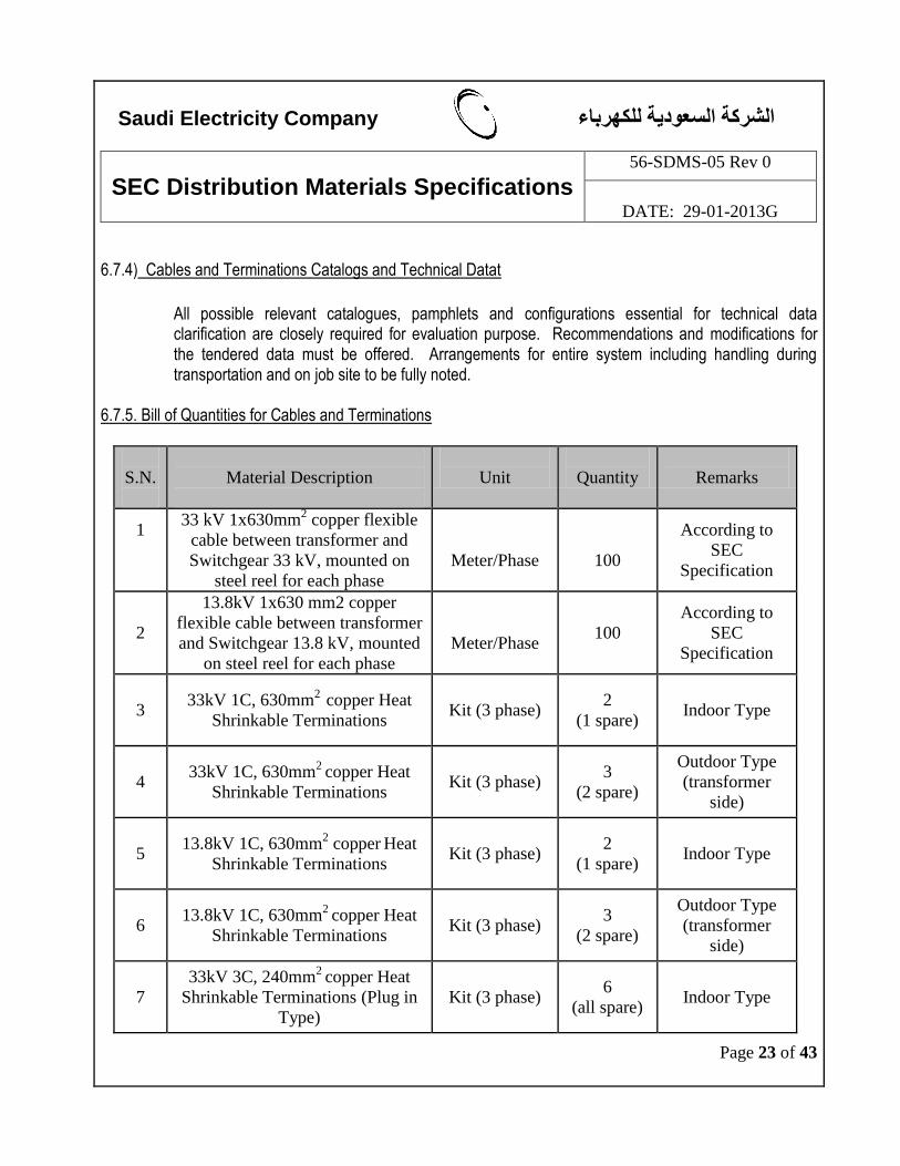
6.7.5. Bill of Quantities for Cables and Terminations
S.N.
Material Description
Unit
Quantity
Remarks
1
33 kV 1x630mm2 copper flexible
cable between transformer and
Switchgear 33 kV, mounted on
steel reel for each phase
Meter/Phase
100
According to
SEC
Specification
2
13.8kV 1x630 mm2 copper
flexible cable between transformer
and Switchgear 13.8 kV, mounted
on steel reel for each phase
Meter/Phase 100
According to
SEC
Specification
3 33kV 1C, 630mm
2 copper Heat
Shrinkable Terminations Kit (3 phase)
2
(1 spare) Indoor Type
4 33kV 1C, 630mm
2 copper Heat
Shrinkable Terminations Kit (3 phase)
3
(2 spare)
Outdoor Type
(transformer
side)
5 13.8kV 1C, 630mm
2 copper
Heat
Shrinkable Terminations Kit (3 phase)
2
(1 spare) Indoor Type
6 13.8kV 1C, 630mm
2 copper Heat
Shrinkable Terminations Kit (3 phase)
3
(2 spare)
Outdoor Type
(transformer
side)
7
33kV 3C, 240mm2
copper Heat
Shrinkable Terminations (Plug in
Type)
Kit (3 phase) 6
(all spare) Indoor Type
Saudi Electricity Company هرباءالشركة السعودية للك
SEC Distribution Materials Specifications
56-SDMS-05 Rev 0
DATE: 29-01-2013G
Page 24 of 43
6.8) Trailer The major specifications of the trailer are as follows: Kingpin : 3.5 inch diameter locking surface conforming to SAE J848a. Kingpin Plate Height (loaded) : 1450 mm Kingpin to Front of Trailer (Max.) : 600 mm Swing Clearance (Min) : 2160 mm Ground Clearance (landing legs : 500 mm at travelling portion Limits for trailer are 4m height, 3.5m width and legth as 10m with maximum towing speed of 50 kph. The minimum turning radius of the combination shall be supplied by the manufacturer. The trailer shall consist of the following accessories, as minimum but not limited to:
a. Chassis: For securely mounting the substation and its components.
b. King Pin: Heavy duty king pin of specifications as mentioned above.
c. Brakes: Air system brakes to hold the trailer under emergency conditions when towing truck is disconnected. The Manufacturer shall specifically indicate the duration for which the emergency brake is active.
d. Spare Tire: Spare tire and rim.
e. Landing Legs: Two speed heavy duty gears change with flat feet for leveling the unit and removing
load from the tyres. More than one leg set is necessary for this application.
f. Chock Blocks: Chock blocks or stopper for use when the substation is parked.
g. Storage Compartment: For storage of substation and trailer spares.
Saudi Electricity Company هرباءالشركة السعودية للك
SEC Distribution Materials Specifications
56-SDMS-05 Rev 0
DATE: 29-01-2013G
Page 25 of 43
h. Warning Lights: Two (2) red lights (minimum) indicating the substation is charged.
i. Lighting: 12 Volt lighting system utilizing towing truck battery system, side markers, stop and tail
lighting shall conform to FMVSS-108 minimum. Wiring shall run through protective conduit and be to ISO standards.
j. Other miscellaneous items like, mud flaps, towing eyes and bumper, connecting structures for in and out going circuits, Jacks, Fork Lift Access, etc.
k. The trailers shall be provided with side covers, doors etc., canopy or collapsible or slidable, to protect
the equipments from weather conditions.
l. A suitable enclosure shall be installed to house all switchgear as well as for locating battery and battery charger, AC & DC distribution System with a provision for an operator for operating the equipments, and enough space for drawing out breakers. The same shall be provided with suitable capacity air conditioner split type, entrance doors, laders, extensions, heat detectors for battery room, smoke detector for switchgear room, Fire Fighting Equipment, etc.
6.9. Nameplates
6.9.1 All main components of mobile substation shall bear a nameplate permanently
and legibly marked in English with the information in accordance with IEC
Standards or equivalent, plus the following additional information :
a. SEC Purchase Order Number or Contract Number or J.O. Number.
b. 56-SDMS-01, Rev.0.
6.9.2 The mobile substation shall have a diagram plate showing incoming/outgoing
winding connections, voltage and current ratios.
6.9.3 All the outgoing feeders shall be provided with blank name plates for writing
the feeder number information.
6.9.4 The nameplate and diagram plate material shall be stainless steel and fastened
to the equipment by stainless steel screws or rivets.
6.9.5 The mobile substation shall have a "Danger High Voltage" warning sign
written in Arabic and English per SEC Standard Drawing nos. SE-036809 and
SB-036084.
Saudi Electricity Company هرباءالشركة السعودية للك
SEC Distribution Materials Specifications
56-SDMS-05 Rev 0
DATE: 29-01-2013G
Page 26 of 43
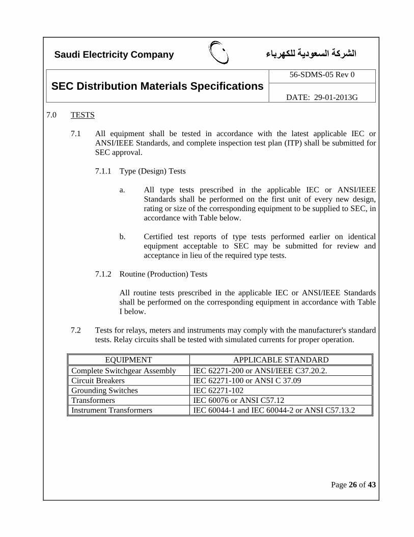
7.0 TESTS
7.1 All equipment shall be tested in accordance with the latest applicable IEC or
ANSI/IEEE Standards, and complete inspection test plan (ITP) shall be submitted for
SEC approval.
7.1.1 Type (Design) Tests
a. All type tests prescribed in the applicable IEC or ANSI/IEEE
Standards shall be performed on the first unit of every new design,
rating or size of the corresponding equipment to be supplied to SEC, in
accordance with Table below.
b. Certified test reports of type tests performed earlier on identical
equipment acceptable to SEC may be submitted for review and
acceptance in lieu of the required type tests.
7.1.2 Routine (Production) Tests
All routine tests prescribed in the applicable IEC or ANSI/IEEE Standards
shall be performed on the corresponding equipment in accordance with Table
I below.
7.2 Tests for relays, meters and instruments may comply with the manufacturer's standard
tests. Relay circuits shall be tested with simulated currents for proper operation.
EQUIPMENT APPLICABLE STANDARD
Complete Switchgear Assembly IEC 62271-200 or ANSI/IEEE C37.20.2.
Circuit Breakers IEC 62271-100 or ANSI C 37.09
Grounding Switches IEC 62271-102
Transformers IEC 60076 or ANSI C57.12
Instrument Transformers IEC 60044-1 and IEC 60044-2 or ANSI C57.13.2
Saudi Electricity Company هرباءالشركة السعودية للك
SEC Distribution Materials Specifications
56-SDMS-05 Rev 0
DATE: 29-01-2013G
Page 27 of 43
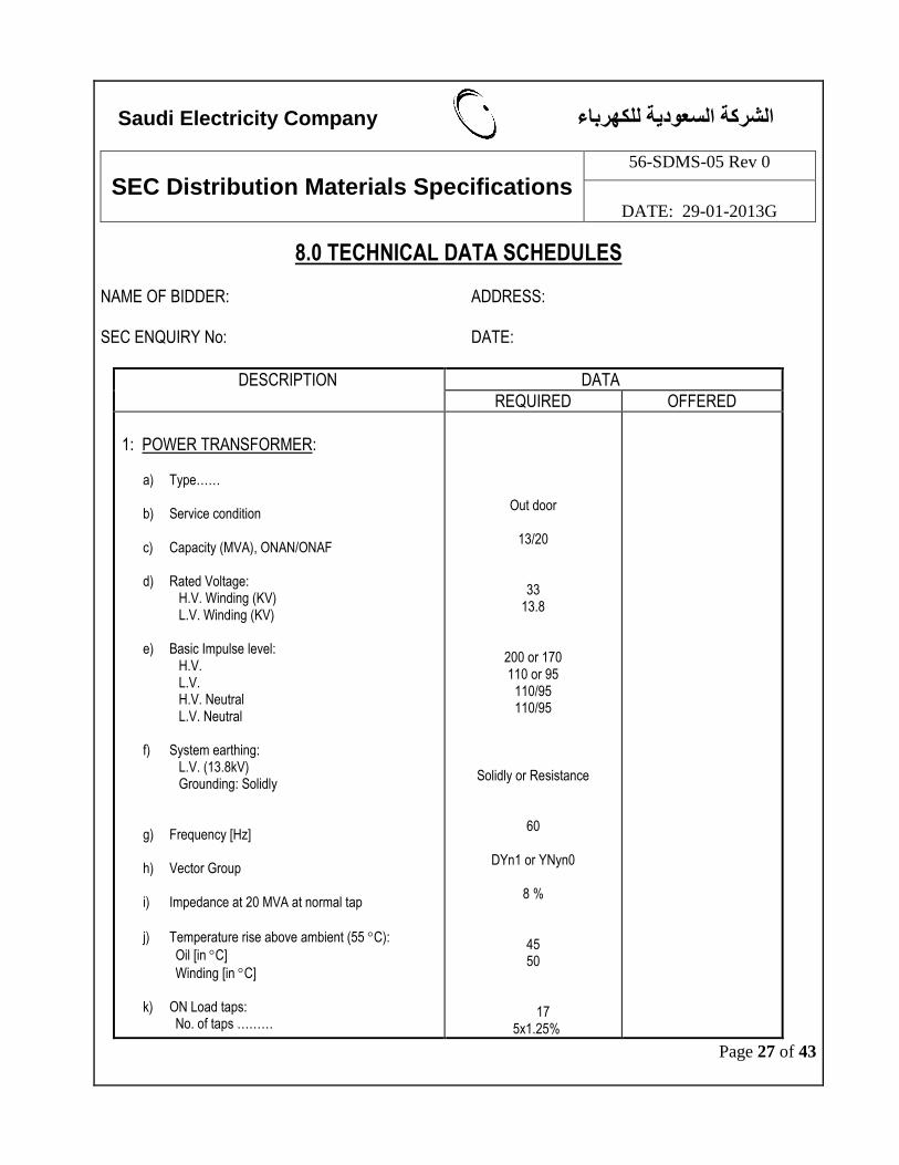
8.0 TECHNICAL DATA SCHEDULES NAME OF BIDDER: ADDRESS: SEC ENQUIRY No: DATE:
DESCRIPTION DATA
REQUIRED OFFERED
1: POWER TRANSFORMER:
a) Type…… b) Service condition
c) Capacity (MVA), ONAN/ONAF
d) Rated Voltage:
H.V. Winding (KV) L.V. Winding (KV)
e) Basic Impulse level: H.V. L.V. H.V. Neutral L.V. Neutral
f) System earthing: L.V. (13.8kV) Grounding: Solidly
g) Frequency [Hz]
h) Vector Group
i) Impedance at 20 MVA at normal tap
j) Temperature rise above ambient (55 C):
Oil [in C]
Winding [in C]
k) ON Load taps: No. of taps ………
Out door
13/20
33 13.8
200 or 170 110 or 95
110/95 110/95
Solidly or Resistance
60
DYn1 or YNyn0
8 %
45 50
17 5x1.25%
Saudi Electricity Company هرباءالشركة السعودية للك
SEC Distribution Materials Specifications
56-SDMS-05 Rev 0
DATE: 29-01-2013G
Page 28 of 43
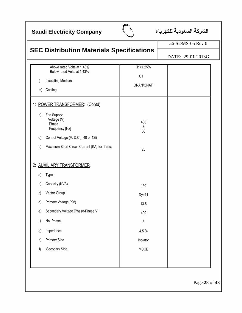
Above rated Volts at 1.43% Below rated Volts at 1.43%
l) Insulating Medium
m) Cooling
11x1.25% Oil ONAN/ONAF
1: POWER TRANSFORMER: (Contd)
n) Fan Supply: Voltage (V) Phase Frequency [Hz]
o) Control Voltage (V. D.C.), 48 or 125
p) Maximum Short Circuit Current (KA) for 1 sec:
2: AUXILIARY TRANSFORMER:
a) Type.
b) Capacity (KVA)
c) Vector Group
d) Primary Voltage (KV)
e) Secondary Voltage [Phase-Phase V]
f) No. Phase
g) Impedance
h) Primary Side i) Secodary Side
400 3
60
25
150
Dyn11
13.8
400
3
4.5 %
Isolator
MCCB
Saudi Electricity Company هرباءالشركة السعودية للك
SEC Distribution Materials Specifications
56-SDMS-05 Rev 0
DATE: 29-01-2013G
Page 29 of 43
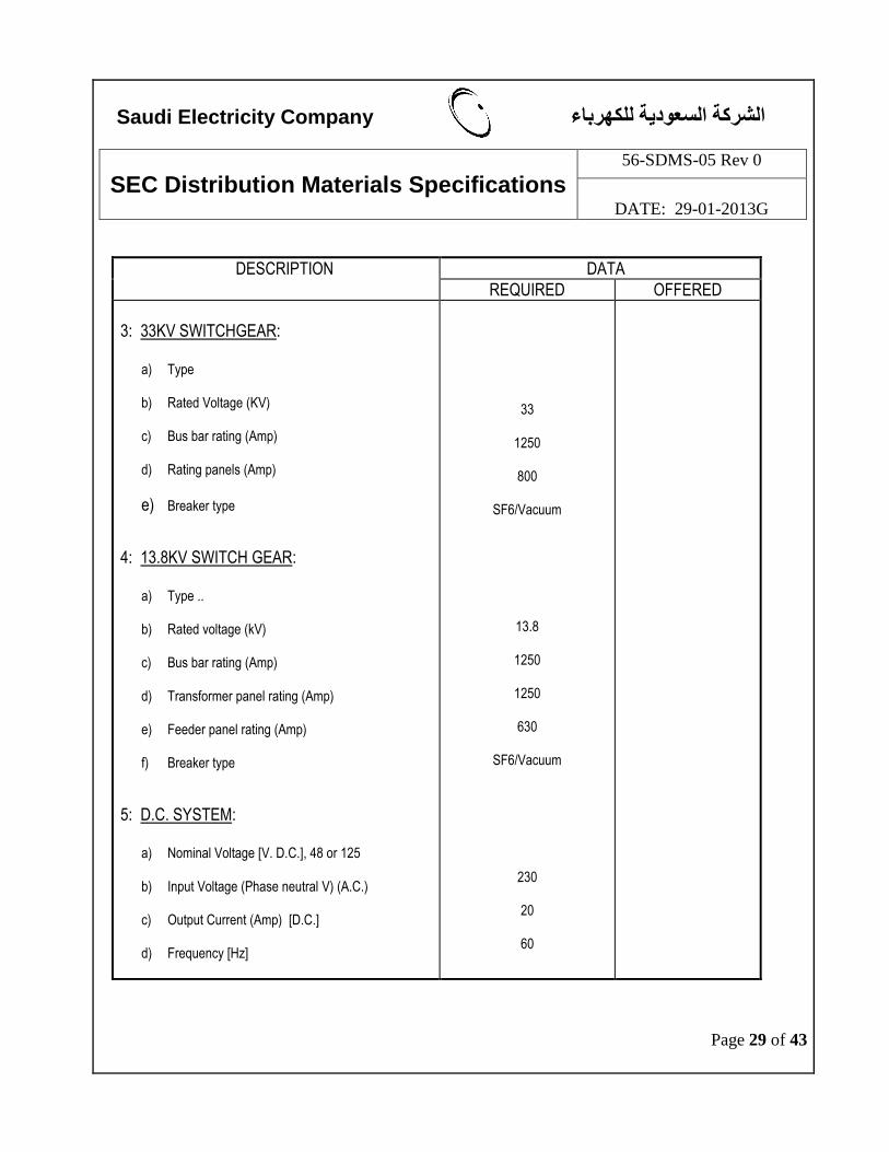
DESCRIPTION DATA
REQUIRED OFFERED
3: 33KV SWITCHGEAR:
a) Type
b) Rated Voltage (KV)
c) Bus bar rating (Amp)
d) Rating panels (Amp)
e) Breaker type
4: 13.8KV SWITCH GEAR:
a) Type ..
b) Rated voltage (kV)
c) Bus bar rating (Amp)
d) Transformer panel rating (Amp)
e) Feeder panel rating (Amp) f) Breaker type
5: D.C. SYSTEM:
a) Nominal Voltage [V. D.C.], 48 or 125
b) Input Voltage (Phase neutral V) (A.C.)
c) Output Current (Amp) [D.C.]
d) Frequency [Hz]
33
1250
800
SF6/Vacuum
13.8
1250
1250
630
SF6/Vacuum
230
20
60
Saudi Electricity Company هرباءالشركة السعودية للك
SEC Distribution Materials Specifications
56-SDMS-05 Rev 0
DATE: 29-01-2013G
Page 30 of 43
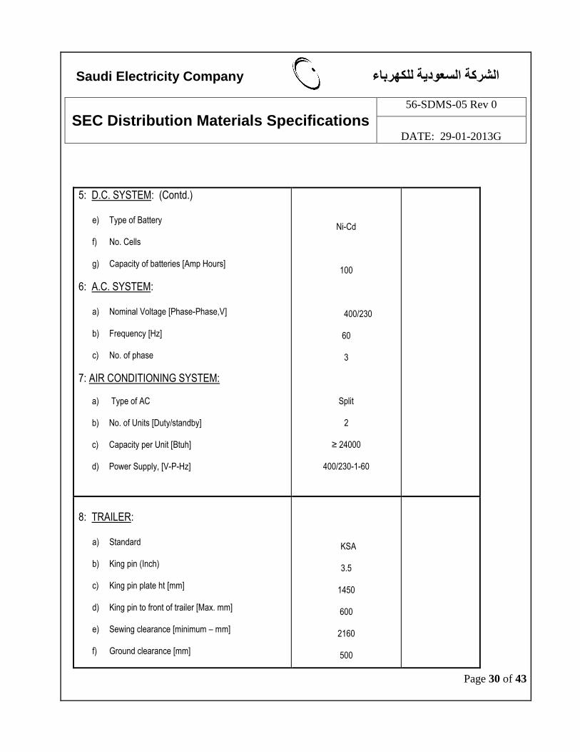
5: D.C. SYSTEM: (Contd.)
e) Type of Battery
f) No. Cells
g) Capacity of batteries [Amp Hours]
6: A.C. SYSTEM:
a) Nominal Voltage [Phase-Phase,V]
b) Frequency [Hz]
c) No. of phase
7: AIR CONDITIONING SYSTEM: a) Type of AC
b) No. of Units [Duty/standby]
c) Capacity per Unit [Btuh]
d) Power Supply, [V-P-Hz]
Ni-Cd
100
400/230
60
3
Split
2
≥ 24000
400/230-1-60
8: TRAILER:
a) Standard
b) King pin (Inch)
c) King pin plate ht [mm]
d) King pin to front of trailer [Max. mm]
e) Sewing clearance [minimum – mm]
f) Ground clearance [mm]
KSA
3.5
1450
600
2160
500
Saudi Electricity Company هرباءالشركة السعودية للك
SEC Distribution Materials Specifications
56-SDMS-05 Rev 0
DATE: 29-01-2013G
Page 31 of 43
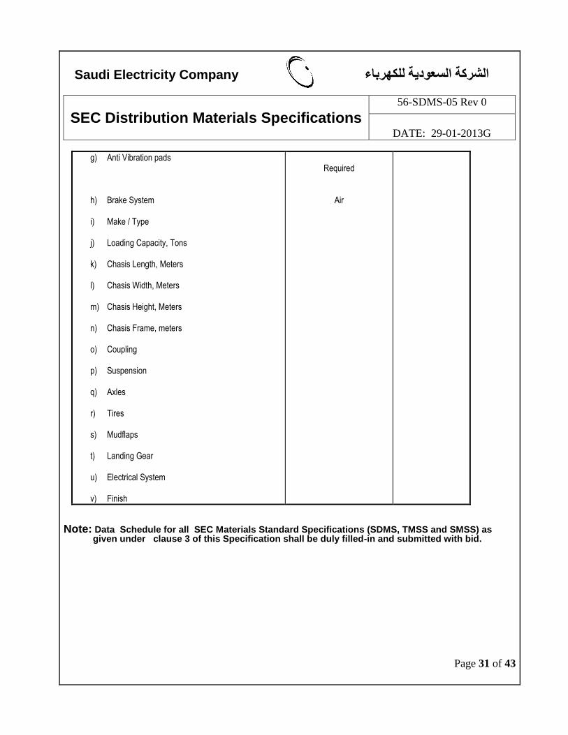
g) Anti Vibration pads
h) Brake System
i) Make / Type
j) Loading Capacity, Tons
k) Chasis Length, Meters
l) Chasis Width, Meters
m) Chasis Height, Meters
n) Chasis Frame, meters
o) Coupling
p) Suspension
q) Axles
r) Tires
s) Mudflaps
t) Landing Gear
u) Electrical System
v) Finish
Required
Air
Note: Data Schedule for all SEC Materials Standard Specifications (SDMS, TMSS and SMSS) as
given under clause 3 of this Specification shall be duly filled-in and submitted with bid.
Saudi Electricity Company هرباءالشركة السعودية للك
SEC Distribution Materials Specifications
56-SDMS-05 Rev 0
DATE: 29-01-2013G
Page 32 of 43
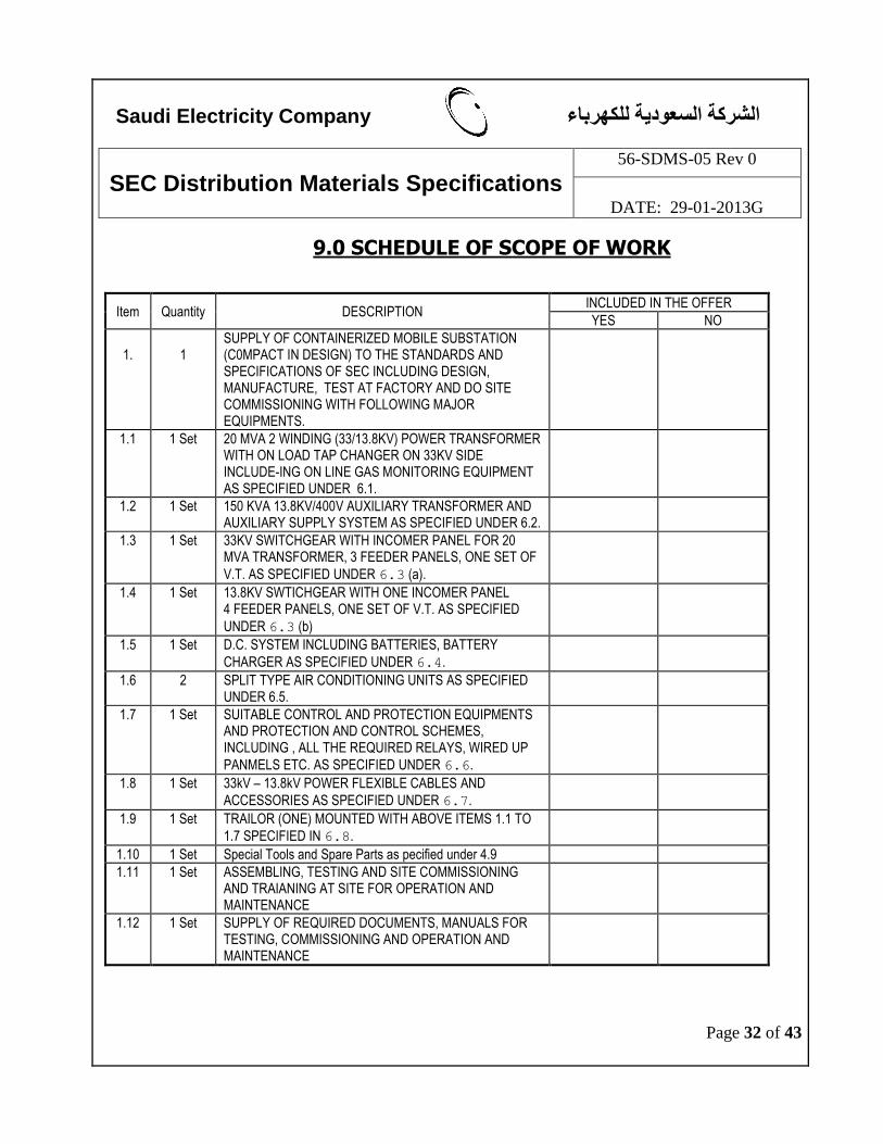
9.0 SCHEDULE OF SCOPE OF WORK
Item Quantity DESCRIPTION INCLUDED IN THE OFFER
YES NO
1.
1
SUPPLY OF CONTAINERIZED MOBILE SUBSTATION (C0MPACT IN DESIGN) TO THE STANDARDS AND SPECIFICATIONS OF SEC INCLUDING DESIGN, MANUFACTURE, TEST AT FACTORY AND DO SITE COMMISSIONING WITH FOLLOWING MAJOR EQUIPMENTS.
1.1 1 Set 20 MVA 2 WINDING (33/13.8KV) POWER TRANSFORMER WITH ON LOAD TAP CHANGER ON 33KV SIDE INCLUDE-ING ON LINE GAS MONITORING EQUIPMENT AS SPECIFIED UNDER 6.1.
1.2 1 Set 150 KVA 13.8KV/400V AUXILIARY TRANSFORMER AND AUXILIARY SUPPLY SYSTEM AS SPECIFIED UNDER 6.2.
1.3 1 Set 33KV SWITCHGEAR WITH INCOMER PANEL FOR 20 MVA TRANSFORMER, 3 FEEDER PANELS, ONE SET OF
V.T. AS SPECIFIED UNDER 6.3 (a).
1.4 1 Set 13.8KV SWTICHGEAR WITH ONE INCOMER PANEL 4 FEEDER PANELS, ONE SET OF V.T. AS SPECIFIED
UNDER 6.3 (b)
1.5 1 Set D.C. SYSTEM INCLUDING BATTERIES, BATTERY
CHARGER AS SPECIFIED UNDER 6.4.
1.6 2 SPLIT TYPE AIR CONDITIONING UNITS AS SPECIFIED UNDER 6.5.
1.7 1 Set SUITABLE CONTROL AND PROTECTION EQUIPMENTS AND PROTECTION AND CONTROL SCHEMES, INCLUDING , ALL THE REQUIRED RELAYS, WIRED UP
PANMELS ETC. AS SPECIFIED UNDER 6.6.
1.8 1 Set 33kV – 13.8kV POWER FLEXIBLE CABLES AND
ACCESSORIES AS SPECIFIED UNDER 6.7.
1.9 1 Set TRAILOR (ONE) MOUNTED WITH ABOVE ITEMS 1.1 TO
1.7 SPECIFIED IN 6.8.
1.10 1 Set Special Tools and Spare Parts as pecified under 4.9
1.11 1 Set ASSEMBLING, TESTING AND SITE COMMISSIONING AND TRAIANING AT SITE FOR OPERATION AND MAINTENANCE
1.12 1 Set SUPPLY OF REQUIRED DOCUMENTS, MANUALS FOR TESTING, COMMISSIONING AND OPERATION AND MAINTENANCE
Saudi Electricity Company هرباءالشركة السعودية للك
SEC Distribution Materials Specifications
56-SDMS-05 Rev 0
DATE: 29-01-2013G
Page 33 of 43
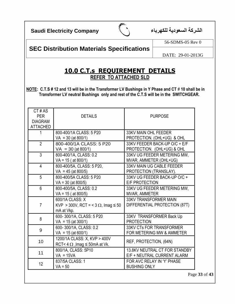
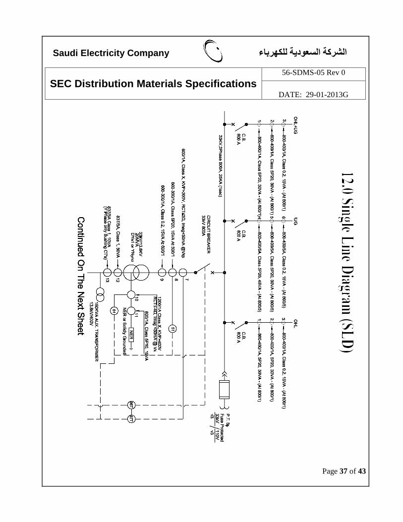
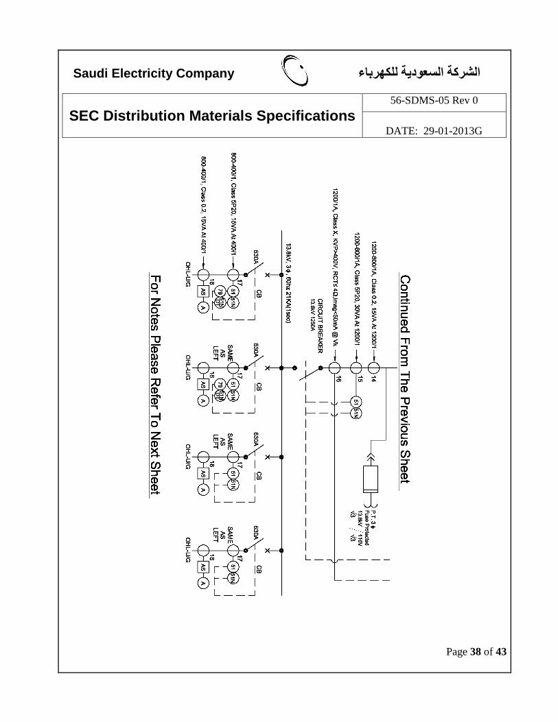
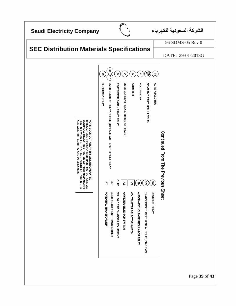
10.0 C.T.s REQUIREMENT DETAILS REFER TO ATTACHED SLD
NOTE: C.T.S # 12 and 13 will be in the Transformer LV Bushings in Y Phase and CT # 10 shall be in Transformer LV neutral Bushings only and rest of the C.T.S will be in the SWITCHGEAR.
CT # AS PER
DIAGRAM ATTACHED
DETAILS
PURPOSE
1
800-400/1A CLASS: 5 P20 VA = 30 (at 800/1)
33KV MAIN OHL FEEDER PROTECTION. (OHL+UG) & OHL
2
800-400/1A CLASS: 5 P20 VA = 30 (at 800/1)
33KV FEEDER BACK-UP O/C + E/F PROTECTION. (OHL+UG) & OHL
3
800-400/1A, CLASS: 0.2 VA = 15 ( at 800/1)
33KV UG FEEDER METERING MW, MVAR, AMMETER (OHL+UG)
4
800-400/5A, CLASS: 5 P20, VA = 45 (at 800/5)
33KV MAIN UG CABLE FEEDER PROTECTION (TRANSLAY).
5
800-400/5A CLASS: 5 P20 VA = 30 (at 800/5)
33KV UG FEEDER BACK-UP O/C + E/F PROTECTION
6
800-400/5A, CLASS: 0.2 VA = 15 ( at 800/5)
33KV UG FEEDER METERING MW, MVAR, AMMETER
7
600/1A CLASS: X
KVP > 300V, RCT = < 3 , Imag ≤ 50 mA at Vkp.
33KV TRANSFORMER MAIN DIFFERENTIAL PROTECTION (87T)
8 600- 300/1A, CLASS: 5 P20 VA = 15 (at 300/1)
33KV TRANSFORMER Back Up PROTECTION
9 600- 300/1A, CLASS: 0.2 VA = 15 (at 600/1)
33KV CTs FOR TRANSFORMER FOR METERING MW & AMMETER
10 1200/1A CLASS: X, KVP > 400V
RCT< 4 ,Imag ≤ 50mA at Vk. REF, PROTECTION, (64N)
11 800/1A, CLASS: 5P10 VA = 15VA
13.8KV NEUTRAL CT FOR STANDBY E/F + NEUTRAL CURRENT ALARM
12 837/5A CLASS: 1 VA = 50
FOR AVC RELAY IN „Y‟ PHASE BUSHING ONLY
Saudi Electricity Company هرباءالشركة السعودية للك
SEC Distribution Materials Specifications
56-SDMS-05 Rev 0
DATE: 29-01-2013G
Page 34 of 43
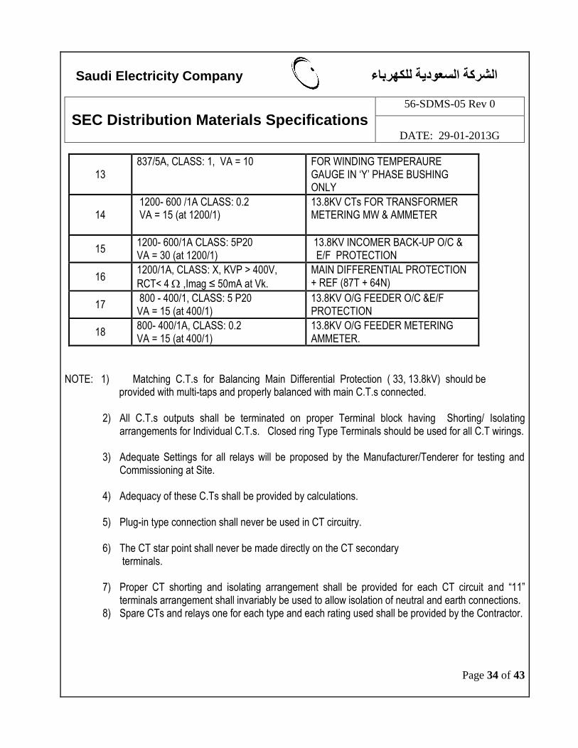
13 837/5A, CLASS: 1, VA = 10 FOR WINDING TEMPERAURE
GAUGE IN „Y‟ PHASE BUSHING ONLY
14 1200- 600 /1A CLASS: 0.2 VA = 15 (at 1200/1)
13.8KV CTs FOR TRANSFORMER METERING MW & AMMETER
15 1200- 600/1A CLASS: 5P20 VA = 30 (at 1200/1)
13.8KV INCOMER BACK-UP O/C & E/F PROTECTION
16 1200/1A, CLASS: X, KVP > 400V,
RCT< 4 ,Imag ≤ 50mA at Vk.
MAIN DIFFERENTIAL PROTECTION + REF (87T + 64N)
17 800 - 400/1, CLASS: 5 P20 VA = 15 (at 400/1)
13.8KV O/G FEEDER O/C &E/F PROTECTION
18 800- 400/1A, CLASS: 0.2 VA = 15 (at 400/1)
13.8KV O/G FEEDER METERING AMMETER.
NOTE: 1) Matching C.T.s for Balancing Main Differential Protection ( 33, 13.8kV) should be
provided with multi-taps and properly balanced with main C.T.s connected.
2) All C.T.s outputs shall be terminated on proper Terminal block having Shorting/ Isolating arrangements for Individual C.T.s. Closed ring Type Terminals should be used for all C.T wirings.
3) Adequate Settings for all relays will be proposed by the Manufacturer/Tenderer for testing and
Commissioning at Site. 4) Adequacy of these C.Ts shall be provided by calculations.
5) Plug-in type connection shall never be used in CT circuitry.
6) The CT star point shall never be made directly on the CT secondary
terminals.
7) Proper CT shorting and isolating arrangement shall be provided for each CT circuit and “11” terminals arrangement shall invariably be used to allow isolation of neutral and earth connections.
8) Spare CTs and relays one for each type and each rating used shall be provided by the Contractor.
Saudi Electricity Company هرباءالشركة السعودية للك
SEC Distribution Materials Specifications
56-SDMS-05 Rev 0
DATE: 29-01-2013G
Page 35 of 43
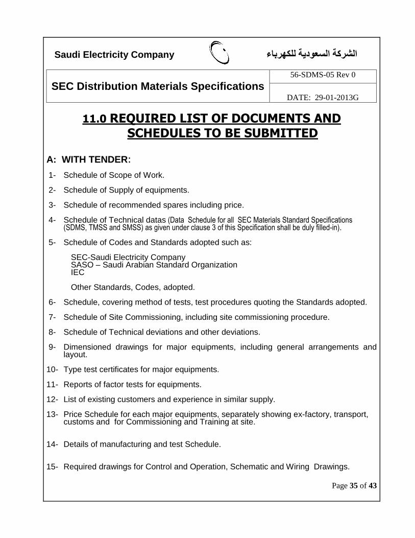
11.0 REQUIRED LIST OF DOCUMENTS AND SCHEDULES TO BE SUBMITTED
A: WITH TENDER: 1- Schedule of Scope of Work. 2- Schedule of Supply of equipments. 3- Schedule of recommended spares including price. 4- Schedule of Technical datas (Data Schedule for all SEC Materials Standard Specifications
(SDMS, TMSS and SMSS) as given under clause 3 of this Specification shall be duly filled-in). 5- Schedule of Codes and Standards adopted such as: SEC-Saudi Electricity Company SASO – Saudi Arabian Standard Organization IEC Other Standards, Codes, adopted. 6- Schedule, covering method of tests, test procedures quoting the Standards adopted. 7- Schedule of Site Commissioning, including site commissioning procedure. 8- Schedule of Technical deviations and other deviations. 9- Dimensioned drawings for major equipments, including general arrangements and
layout. 10- Type test certificates for major equipments. 11- Reports of factor tests for equipments. 12- List of existing customers and experience in similar supply.
13- Price Schedule for each major equipments, separately showing ex-factory, transport,
customs and for Commissioning and Training at site.
14- Details of manufacturing and test Schedule. 15- Required drawings for Control and Operation, Schematic and Wiring Drawings.
Saudi Electricity Company هرباءالشركة السعودية للك
SEC Distribution Materials Specifications
56-SDMS-05 Rev 0
DATE: 29-01-2013G
Page 36 of 43
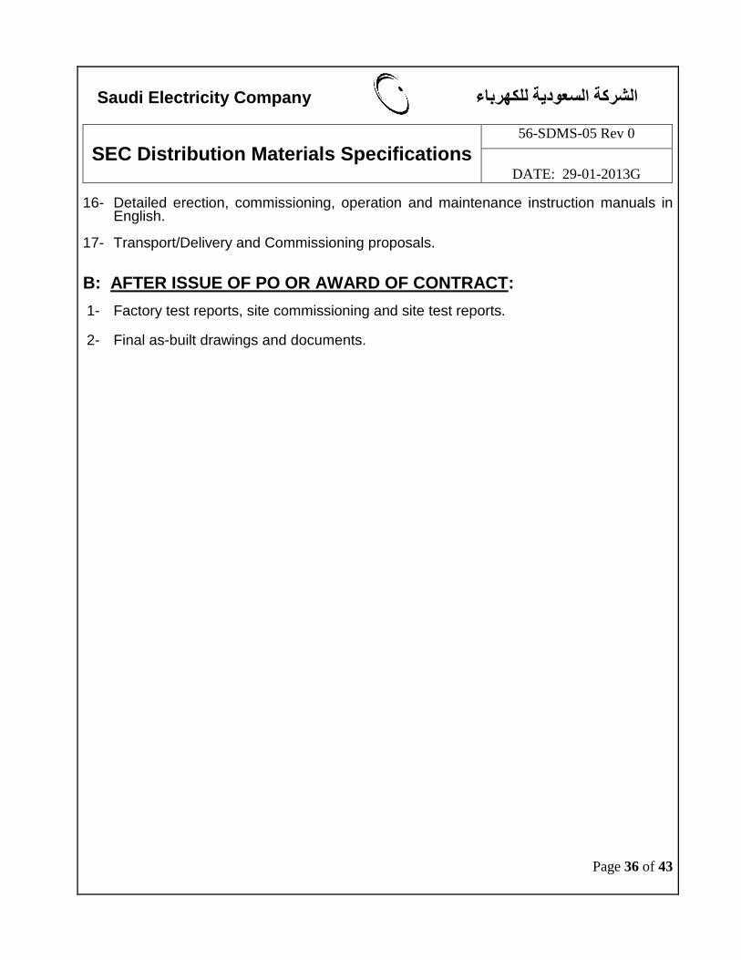
16- Detailed erection, commissioning, operation and maintenance instruction manuals in English.
17- Transport/Delivery and Commissioning proposals. B: AFTER ISSUE OF PO OR AWARD OF CONTRACT:
1- Factory test reports, site commissioning and site test reports. 2- Final as-built drawings and documents.
Saudi Electricity Company هرباءالشركة السعودية للك
SEC Distribution Materials Specifications
56-SDMS-05 Rev 0
DATE: 29-01-2013G
Page 37 of 43
Saudi Electricity Company هرباءالشركة السعودية للك
SEC Distribution Materials Specifications
56-SDMS-05 Rev 0
DATE: 29-01-2013G
Page 38 of 43
Saudi Electricity Company هرباءالشركة السعودية للك
SEC Distribution Materials Specifications
56-SDMS-05 Rev 0
DATE: 29-01-2013G
Page 39 of 43
Saudi Electricity Company هرباءالشركة السعودية للك
SEC Distribution Materials Specifications
56-SDMS-05 Rev 0
DATE: 29-01-2013G
Page 40 of 43
13.0 Pilot Termination, Isolation and Supervision Box with 5kV Insulation
1. SCOPE
This clause details the basic requirements for terminating one or two twelve-pair pilot
cables and up to 10 outgoing multicore cables with facilities for pilot isolation, 5kV pilot
insulation and send or receive end pilot supervision.
2. GENERAL
2.1 The pilot boxes covered by this specification are for use with pilot wire protection and possible
emergency tripping schemes in the case of consumer's feeders, on either 13.8kV or 33kV power
cables where a 5kV pilot insulation level is required.
2.2 Two main types of boxes are required, one with send end pilot supervision and one with receive
end pilot supervision.
2.3 In the case of multiple installations required for a turnkey contract, it is permissible for one box
to contain all the equipment required for two cable circuits. In such cases, the double circuit box
could be equipped with two send ends, two receive ends or one send end and one receive end pilot
supervision. The exact requirements shall be specified at the time of ordering.
3. ENCLOSURE
3.1 The box shall be made out of polyester reinforced with fiberglass and shall be self-extinguishing.
3.2 The box shall be fitted with four external brackets to facilitate wall mounting of boxes side-by
side if necessary.
3.3 The front of the box shall comprise a door which is hinged on the left. The door shall be fitted
with two closing handles which do not have any integral key locking arrangement. A suitable
bracket shall be fitted to J the center of the right side of the door to allow locking with a padlock
having a hasp diameter of 6 mm with 25 mm clearance. The door shall be suitably sealed to
prevent the ingress of dust to class IPSO of IEC 529.
3.4 The top and bottom of the box shall each have a suitable cut-out for mounting a cable gland plate
for the outgoing multicore cables and pilot cables respectively.
3.5 When pilot box is associated with two cable feeders, the necessary equipment shall be mounted
to the left for one cable feeder and to the right for the other cable-feeder. A barrier of insulating
material not less than 100mm deep shall be fixed in the center to segregate the 2 sets of
Saudi Electricity Company هرباءالشركة السعودية للك
SEC Distribution Materials Specifications
56-SDMS-05 Rev 0
DATE: 29-01-2013G
Page 41 of 43
equipment.
3.6 The box and door shall be finished in shade RAL-7033 -Grey.
4. CONSTRUCTION
4.1 All the internal components of the box shall be mounted on a mild-steel back plate with fixing
brackets and rails as appropriate.
4.2 The exact layout and dimensions are left to the manufacturer.
5. CABLE GLAND PLATES
5.1 Two mild-steel cable gland plates shall be provided. These shall not be drilled to accept cables
unless specifically requested at the time of order. All gland plates shall be of sufficient strength to
prevent distortion in use.
5.2 The top gland plate shall be of sufficient size to accommodate the maximum number of
multicore
cable glands depending on the type of box as follows:
For pilot box with SEND END pilot supervision:
1 Cable gland for 7 core 2.5 mm2 PVC/PVC/SWA/PVC cable for protection.
2 Cable glands for 4 core 2.5 mm2 PVC/PVC/SWA/PVC cables for supplies.
For pilot box with RECEIVE END pilot supervision:
1 Cable gland for 7 core 2.5 mm2 PVC/PVC/SWA/PVC cable for protection.
In addition to the above, for each consumers feeder which requires emergency tripping facilities,
the top gland plate shall also accommodate one cable gland for 4 core 2.5 mm2
PVC/PVC/SWA/PVC 5kV insulated cable for the emergency tripping push button or receive relay
as appropriate.
5.3 The bottom gland plate shall be of sufficient size to accommodate one cable gland for the 12 core
0.9 mm diameter PVC/PVC/SWA/PVC 5kV insulated pilot cable.
5.4 For a pilot box which is associated with two cable feeders, each gland plate shall be of sufficient
size to accommodate all the necessary cables for both feeders in line with 5.2 and 5.3 above.
5.5 For a pilot box associated with a mobile s/s where all the cables are accommodated requiring
bottom entry, the requirement for the top gland plate may be deleted. The bottom gland plate shall
then be suitable for all the cable entries with the pilot cables on the right
and the multicore cables on the left.
5.6 Adequate cable glands to suit the application shall be supplied as loose equipment inside the box.
Saudi Electricity Company هرباءالشركة السعودية للك
SEC Distribution Materials Specifications
56-SDMS-05 Rev 0
DATE: 29-01-2013G
Page 42 of 43
6. PILOT SUPERVISION EQUIPMENT
6.1 Pilot wire supervision equipment shall be installed in the box for either send end or receive end
functions. The equipment shall be fully compatible with the pilot wire protection relays which
shall be specified at the time of ordering. The pilot supervision equipment shall detect open
circuit, short-circuit or crossed pilots and loss of supervision supply.
7. PILOT ISOLATION EQUIPMENT
7.1 For each pilot wire protection, a suitable pilot isolation transformer shall be supplied and fitted in
the send or receive end box if required in order to achieve a 5kV insulation level between the pilot
wires and the protection equipment. The ratio of the transformer shall be as recommended by the
pilot wire protection manufacturer.
7.2 An additional suitable pilot isolation transformer shall be supplied and fitted in the send end box
in order to achieve a 5kV insulation level between the pilot wires and the pilot wire supervision
equipment as covered in Section 6.1 above.
8. TERMINAL BLOCKS ANO WIRING
8.1 For each pilot wire protection, a vertically mounted group of 13 terminal blocks shall be
provided
which have a 5kV insulation level. Each terminal block shall be fitted with an isolating plug link.
A shorting bar shall be fitted on the equipment side of the terminal blocks.
8.2 The group of 5kV terminals shall be mounted towards the bottom right of the box and the lowest
two terminal blocks shall be used for the pilot wire protection pair. The 11 terminal blocks above
shall be used for the spare pairs of the pilot cable.
8.3 For each pilot wire protection a vertically-mounted group of 15 or 7 terminal blocks shall be
provided for send end or receive end supervision respectively. These terminal blocks shall be
insulated to 2kV. The group of 2kV terminals shall be mounted towards the top left of the box.
8.4 All terminals which are insulated to the 5kV or 2kV levels shall be suitably shrouded.
8.5 All wiring which is directly connected to the pilot wires shall be insulated to at least 5kV.
8.6 All other wiring shall be insulated to at least 2kV.
8.7 The 5kV insulated wiring shall be segregated from all other wiring.
8.8 For send end pilot supervision, 8 of the 2kV terminals shall be for AC and DC auxiliary supplies.
For send or receive end pilot supervision, 7 of the 2kV terminals shall be for protection and alarm.
Saudi Electricity Company هرباءالشركة السعودية للك
SEC Distribution Materials Specifications
56-SDMS-05 Rev 0
DATE: 29-01-2013G
Page 43 of 43
9. GROUNDING
9.1 The main earth connection to the box shall be via an M10 brass earth stud which protrudes
through the base of the box. The earth stud shall be supplied with washers and locking nuts etc., to
permit an earth bond to be made to the substation main earth.
9.2 All internal exposed metallic parts shall be effectively earthed to the earth stud via a removable
link which is mounted on a barrel insulator rated at least 5kV. A small grounding strip shall
facilitate multiple connections.
9.3 Two wandering earth leads 6 mm2 multi-strand PVC cable color green/ yellow shall be provided.
Each shall be long enough to earth any pilot cable core.
9.4 The cable gland plates shall be effectively earthed to the grounding strip by 35 mm2 copper
connections with 5kV insulation.
10. LABELLING
10.1 All labels shall be made out of laminated plastic which, unless otherwise specified, shall be
suitable for black letters on a white background.
10.2 All labels shall be fixed to the appropriate surface using self-tapping, screws and labels shall not
be fixed to removable shrouds.
10.3 A label shall be fixed near the top of the door, which shall be at least 180mm x 50mm. The top
line of text shall read 'PILOT WIRE PROTECTION'. The second line of text shall read as
appropriate:
PILOT ISOLATION SEND END BOX
or PILOT ISOLATION RECEIVE END BOX
or PILOT-ISOLATION SEND AND RECEIVE END BOX
10.4 A label shall be fixed near the bottom of the door having red letters on a white background and
at least 190mm x 50mm. The text shall read:
CAUTION: CONNECTIONS SUBJECT TO HIGH VOLTAGES
EARTH PILOT CORES BEFORE HANDLING
10.5 On the center of the door shall be fixed a label 150mm x 50mm. This label shall be left blank so
that it can be engraved by SCECO after erection on site to indicate the feeder number. In the case
of a box for two cable circuits, two labels as above shall be fixed on the door, one on the left and
one on the right.
10.6 Two further blank labels 75mm x 25mm shall be fixed to the internal back plate, one on the left
and one on the right, for engraving by SCECO following erection on site to indicate the feeder
numbers. The location of each label shall be chosen to maximize legibility and access, having due
regard to the layout of all the components on the back plate and the necessary wiring.
10.7 Suitable labels shall be fixed adjacent to each group of terminal blocks to identify their use.