Embed Size (px)
Citation preview
SECA Core Technology Program and Small Scale SOFC Test Platform
J. Hardy, B. Koeppel, Y. Chou, J. Choi, C. Coyle, Z. Xu, N. Karri, J. Bao, B. Kirby, G. Whyatt,
J. Davis, C. Fischer, C. Lowrey, N. Canfield, J. Fitzpatrick, T. Droubay, B. Nguyen, C. Mason,
D. Wang, X. Yang, J. Kim, M. Prange

2
Small-Scale SOFC Stack Test Platform• Commissioned by DOE for independent
evaluation of performance and reliability of emerging stack technologies (2-7 kW)under realistic operating conditions
• Demonstrated test stand capabilities: Steam-reformed methane or natural gas Steady-state isothermal tests
Variables: temperature, current, voltage, fuel Thermal cycling E-stop cycles (redox tolerance) Variable anode recycle rates Gross efficiency: 56% HHV, 62% LHV
• Recent efforts have been dedicated to upgrading the platform for use with commercial natural gas, including addition of sulfur traps and automated sulfur gas sampling/analysis.
3
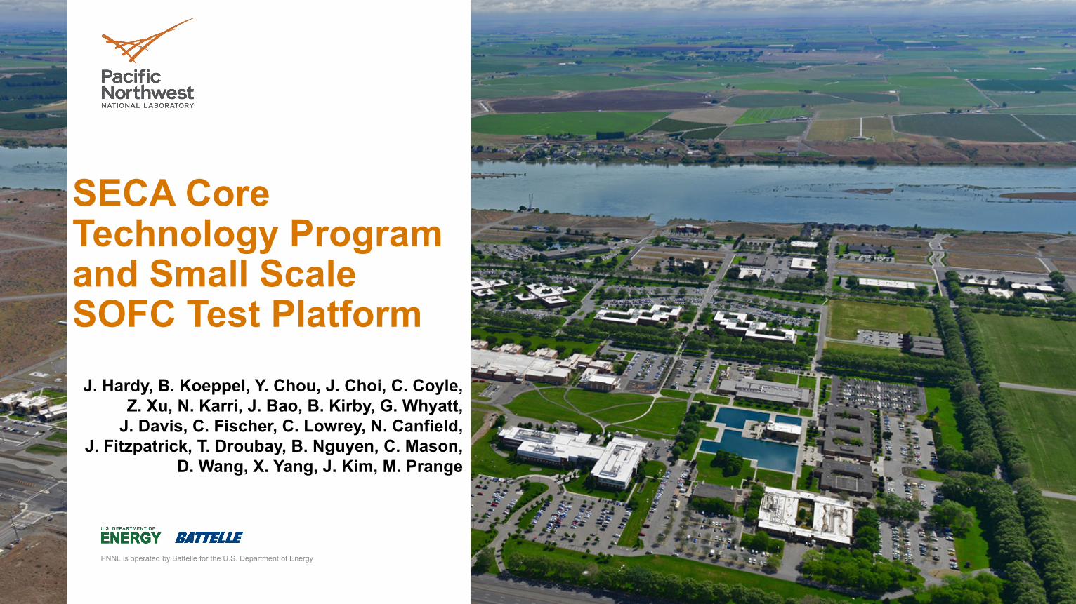
Natural Gas Supply and Compression
Added Natural Gas Supply And Compression• Compress natural gas to
20 -30 psig to allow mass flow controller operation
• Safety Features Excess flow valve
protection Shuts down for loss of
downstream pressure Can be inerted prior to
receiving natural gas
Compressor
Filter
NG Supply to Compressor
Inert Supply to Compressor
Excess Flow Valve
Filter
To Desulfurization
Outlet
4
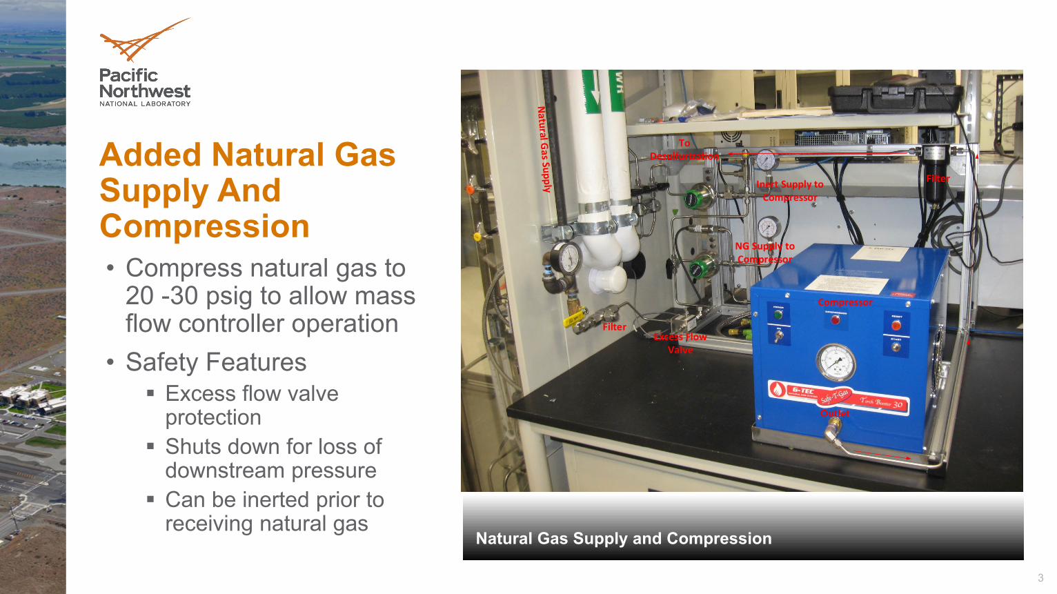
Natural Gas Supply Desufurization
Natural Gas Desulfurization
• Provided by SulfaTrap, LLC, consisting of combination of X1 and X5 materials
• 20 slpm flow• Outlet <10ppbv• 12,000 h life• Replaceable cartridge
Desulfurizer
To S
yste
m
5
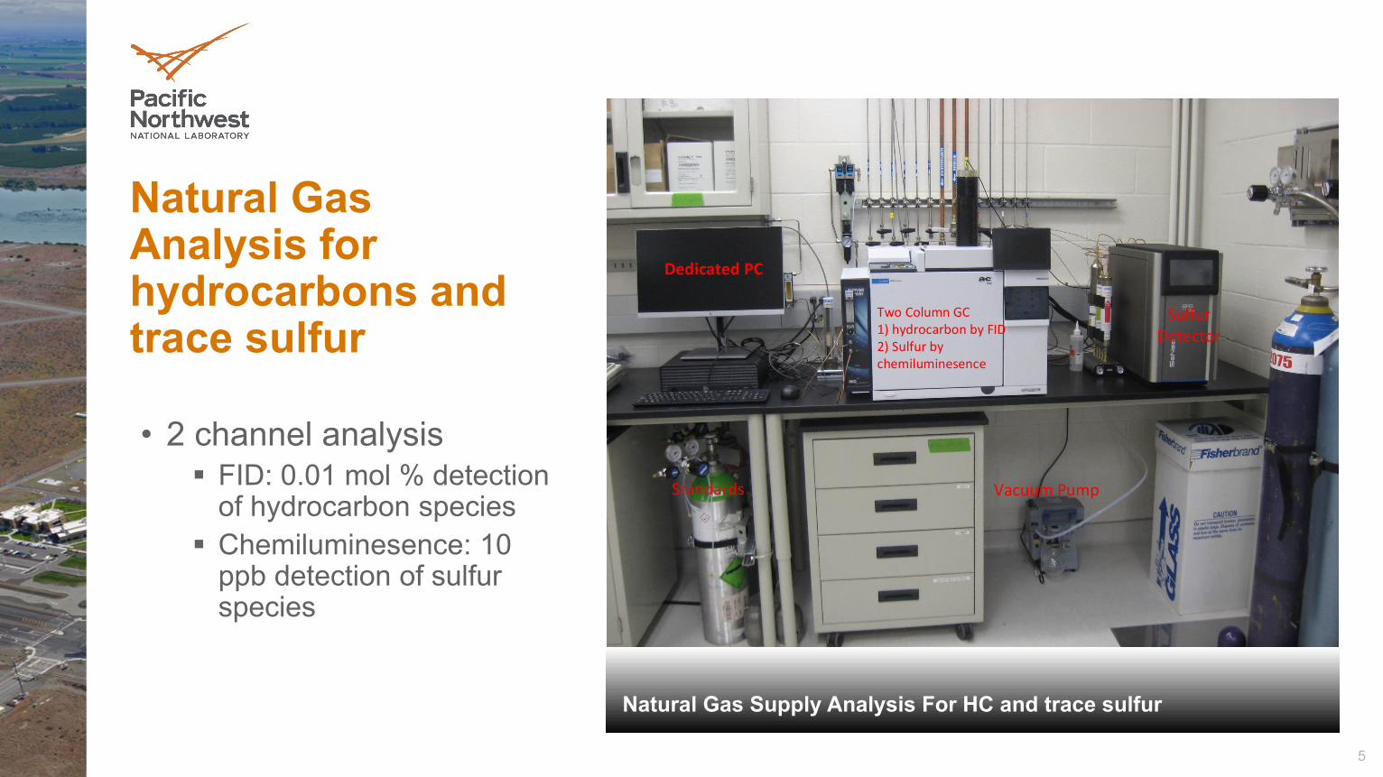
Natural Gas Supply Analysis For HC and trace sulfur
Natural Gas Analysis for hydrocarbons and trace sulfur
• 2 channel analysis FID: 0.01 mol % detection
of hydrocarbon species Chemiluminesence: 10
ppb detection of sulfur species
Dedicated PC
Two Column GC1) hydrocarbon by FID2) Sulfur by chemiluminesence
Sulfur Detector
Vacuum PumpStandards
6
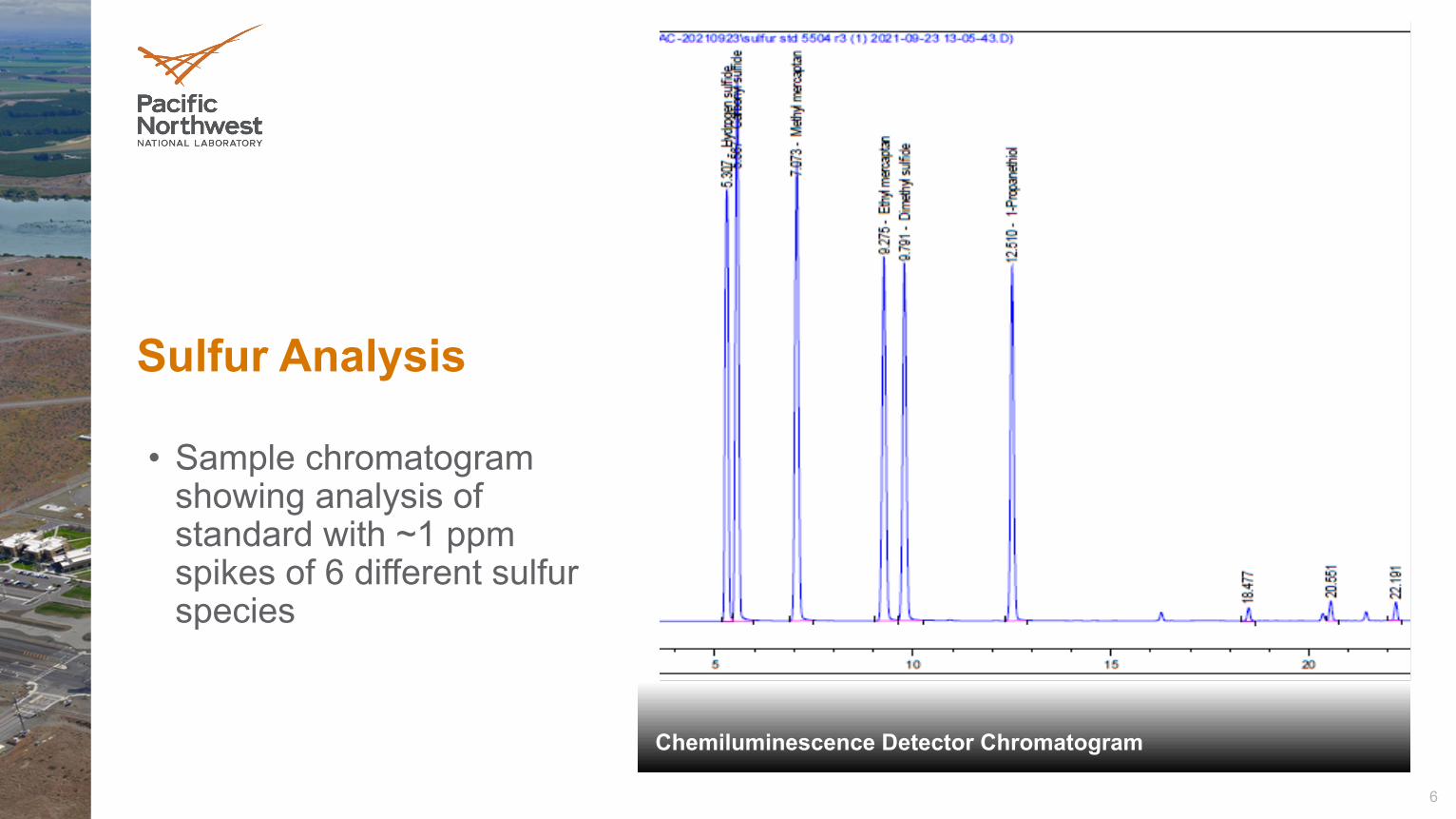
Chemiluminescence Detector Chromatogram
Sulfur Analysis
• Sample chromatogram showing analysis of standard with ~1 ppm spikes of 6 different sulfur species
7
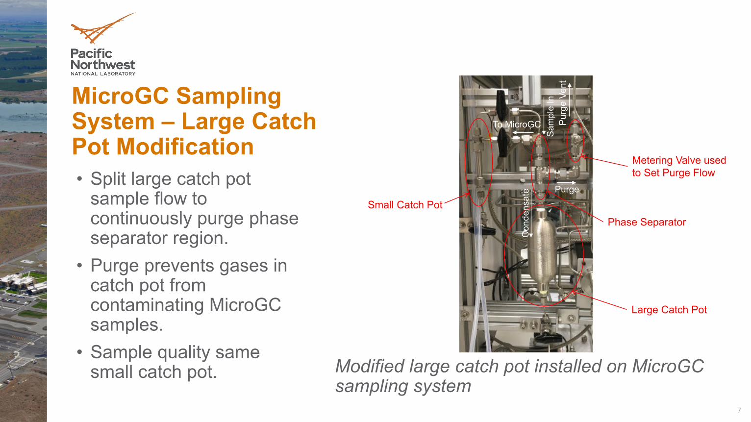
Modified large catch pot installed on MicroGCsampling system
• Split large catch pot sample flow to continuously purge phase separator region.
• Purge prevents gases in catch pot from contaminating MicroGCsamples.
• Sample quality same small catch pot.
MicroGC Sampling System – Large Catch Pot Modification
Small Catch Pot
Large Catch Pot
Phase Separator
Metering Valve used to Set Purge Flow
Sam
ple
In
To MicroGC Purg
e Ve
nt
Con
dens
ate Purge
8
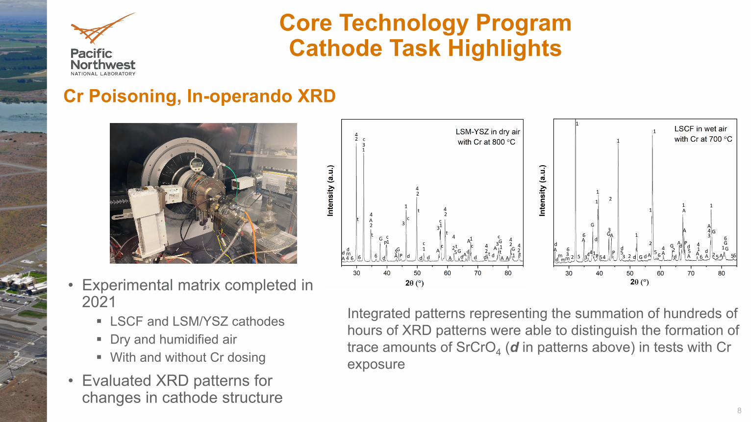
• Experimental matrix completed in 2021 LSCF and LSM/YSZ cathodes Dry and humidified air With and without Cr dosing
• Evaluated XRD patterns for changes in cathode structure
Cr Poisoning, In-operando XRD
Core Technology Program Cathode Task Highlights
Integrated patterns representing the summation of hundreds of hours of XRD patterns were able to distinguish the formation of trace amounts of SrCrO4 (d in patterns above) in tests with Cr exposure
9
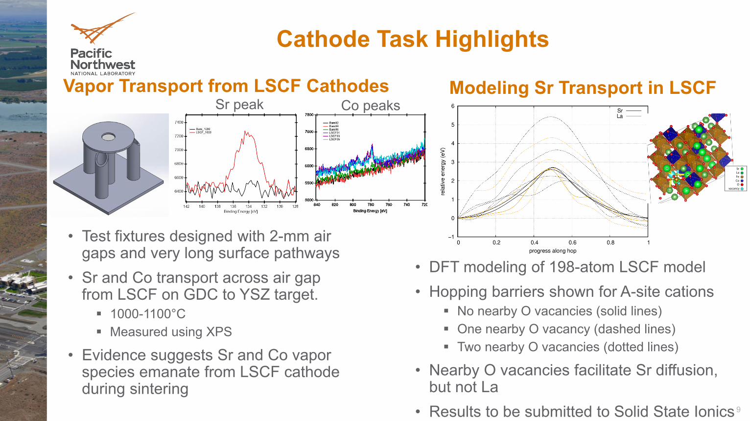
• Test fixtures designed with 2-mm air gaps and very long surface pathways
• Sr and Co transport across air gap from LSCF on GDC to YSZ target. 1000-1100°C Measured using XPS
• Evidence suggests Sr and Co vapor species emanate from LSCF cathode during sintering
Vapor Transport from LSCF Cathodes Modeling Sr Transport in LSCF
• DFT modeling of 198-atom LSCF model• Hopping barriers shown for A-site cations
No nearby O vacancies (solid lines) One nearby O vacancy (dashed lines) Two nearby O vacancies (dotted lines)
• Nearby O vacancies facilitate Sr diffusion, but not La
• Results to be submitted to Solid State Ionics
Cathode Task Highlights
Sr peak Co peaks
SrLaFeCoO
vacancy
10
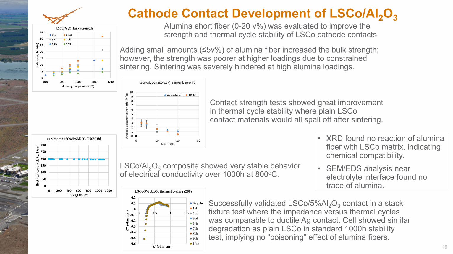
• XRD found no reaction of alumina fiber with LSCo matrix, indicating chemical compatibility.
• SEM/EDS analysis near electrolyte interface found no trace of alumina.
Cathode Contact Development of LSCo/Al2O3
Adding small amounts (≤5v%) of alumina fiber increased the bulk strength; however, the strength was poorer at higher loadings due to constrained sintering. Sintering was severely hindered at high alumina loadings.
Contact strength tests showed great improvement in thermal cycle stability where plain LSCocontact materials would all spall off after sintering.
LSCo/Al2O3 composite showed very stable behavior of electrical conductivity over 1000h at 800oC.
Successfully validated LSCo/5%Al2O3 contact in a stack fixture test where the impedance versus thermal cycles was comparable to ductile Ag contact. Cell showed similar degradation as plain LSCo in standard 1000h stability test, implying no “poisoning” effect of alumina fibers.
Alumina short fiber (0-20 v%) was evaluated to improve the strength and thermal cycle stability of LSCo cathode contacts.
11
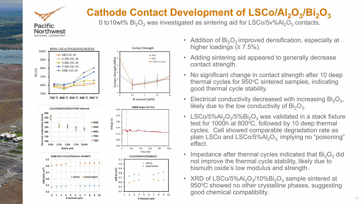
• Addition of Bi2O3 improved densification, especially at higher loadings (≥ 7.5%).
• Adding sintering aid appeared to generally decrease contact strength.
• No significant change in contact strength after 10 deep thermal cycles for 950oC sintered samples, indicating good thermal cycle stability.
• Electrical conductivity decreased with increasing Bi2O3, likely due to the low conductivity of Bi2O3.
• LSCo/5%Al2O3/5%Bi2O3 was validated in a stack fixture test for 1000h at 800oC, followed by 10 deep thermal cycles. Cell showed comparable degradation rate as plain LSCo and LSCo/5%Al2O3, implying no “poisoning” effect.
• Impedance after thermal cycles indicated that Bi2O3 did not improve the thermal cycle stability, likely due to bismuth oxide’s low modulus and strength.
• XRD of LSCo/5%Al2O3/10%Bi2O3 sample sintered at 950oC showed no other crystalline phases, suggesting good chemical compatibility.
Cathode Contact Development of LSCo/Al2O3/Bi2O30 to10wt% Bi2O3 was investigated as sintering aid for LSCo/5v%Al2O3 contacts.
12
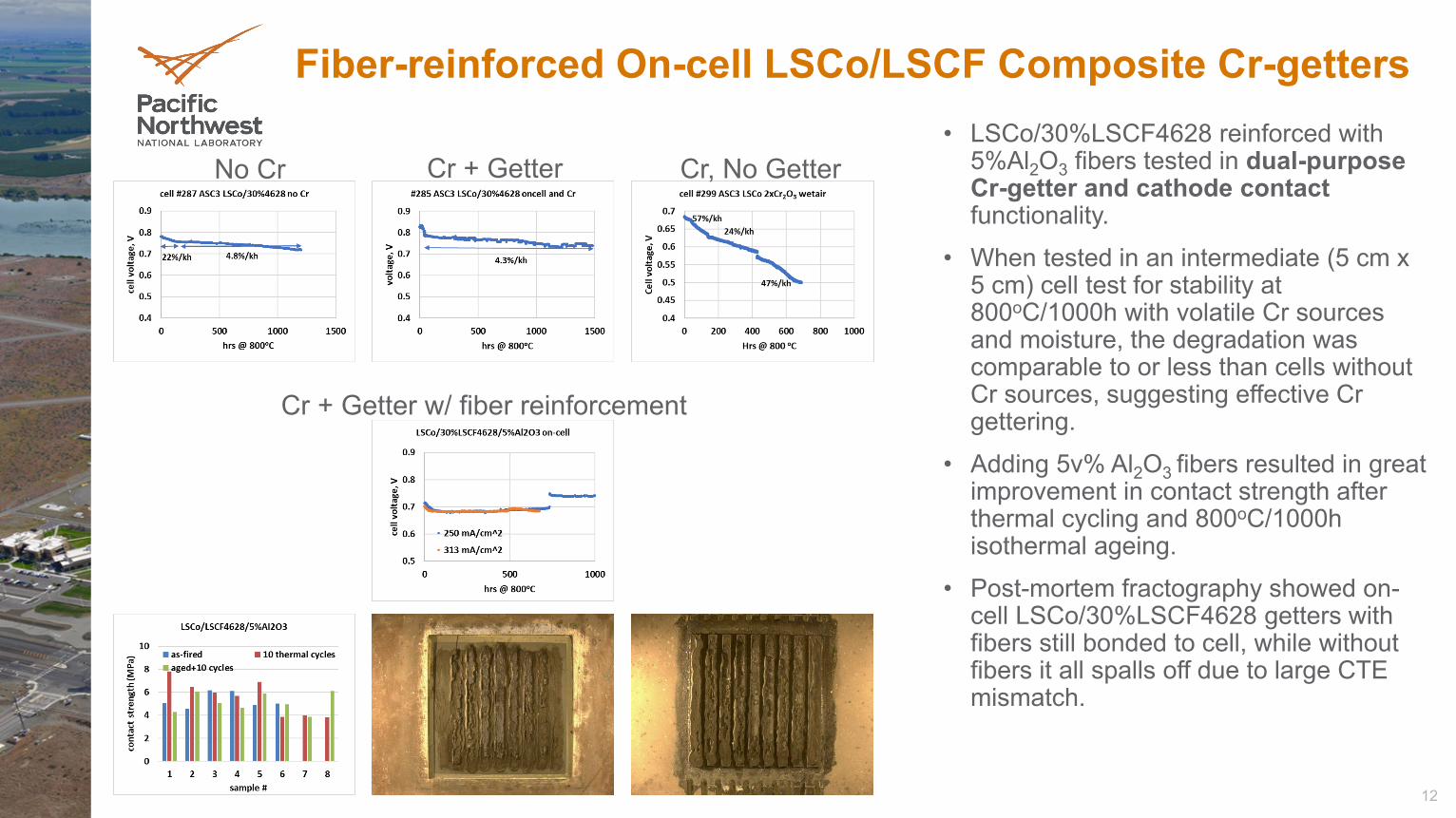
• LSCo/30%LSCF4628 reinforced with 5%Al2O3 fibers tested in dual-purpose Cr-getter and cathode contact functionality.
• When tested in an intermediate (5 cm x 5 cm) cell test for stability at 800oC/1000h with volatile Cr sources and moisture, the degradation was comparable to or less than cells without Cr sources, suggesting effective Cr gettering.
• Adding 5v% Al2O3 fibers resulted in great improvement in contact strength after thermal cycling and 800oC/1000h isothermal ageing.
• Post-mortem fractography showed on-cell LSCo/30%LSCF4628 getters with fibers still bonded to cell, while without fibers it all spalls off due to large CTE mismatch.
Fiber-reinforced On-cell LSCo/LSCF Composite Cr-getters
No Cr Cr + Getter Cr, No Getter
Cr + Getter w/ fiber reinforcement
13
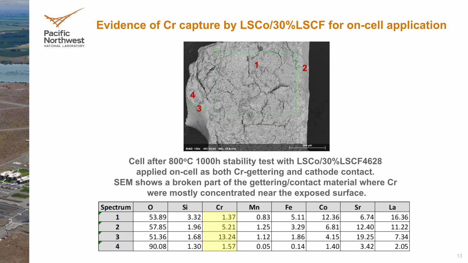
Evidence of Cr capture by LSCo/30%LSCF for on-cell application
Cell after 800oC 1000h stability test with LSCo/30%LSCF4628 applied on-cell as both Cr-gettering and cathode contact.
SEM shows a broken part of the gettering/contact material where Cr were mostly concentrated near the exposed surface.
1 2
34
14
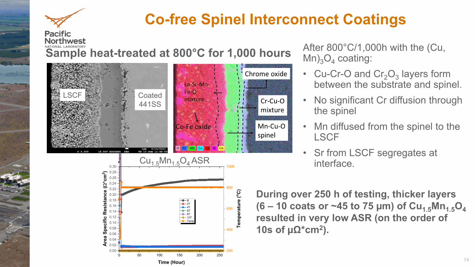
Sample heat-treated at 800°C for 1,000 hours
Co-free Spinel Interconnect Coatings
0 50 100 150 200 2500.000.020.040.060.080.100.120.140.160.180.200.220.240.260.280.30
B 2T 4T 6T 8T 10T Temp
Time (Hour)
Are
a Sp
ecifi
c R
esis
tanc
e (Ω
*cm
2 )
200
400
600
800
1000
Tem
pera
ture
(o C)
Cu1.5Mn1.5O4 ASR
Coated441SS
LSCF
After 800°C/1,000h with the (Cu, Mn)3O4 coating: • Cu-Cr-O and Cr2O3 layers form
between the substrate and spinel.• No significant Cr diffusion through
the spinel • Mn diffused from the spinel to the
LSCF• Sr from LSCF segregates at
interface.
During over 250 h of testing, thicker layers (6 – 10 coats or ~45 to 75 µm) of Cu1.5Mn1.5O4resulted in very low ASR (on the order of 10s of µΩ*cm2).
15
Modeling Task Overview
Objective• Develop numerical models (primarily at the cell and stack scale), analysis methods,
and software tools to improve the thermal-mechanical performance, reliability, and stability of SOFC materials.
FY21 Accomplishments• Adapted SOFC modeling tools for SOEC operation.• Developed user interface for automated generation of SOFC reduced order models
(ROMs).• Used machine learning (ML) to enhance ROM accuracy.• Developed constitutive model to characterize damage to ceramic cell components
due to thermal-mechanical stresses from assembly, operating, shutdown, and transient thermal conditions.
• Used damage model to evaluate stresses due to anode reduction-oxidation (RedOx).• Obtained Weibull strength for reinforced cathode contact material.
16
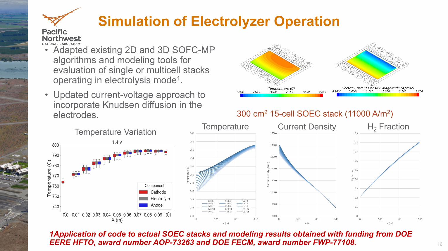
Simulation of Electrolyzer Operation
• Adapted existing 2D and 3D SOFC-MP algorithms and modeling tools for evaluation of single or multicell stacks operating in electrolysis mode1.
• Updated current-voltage approach to incorporate Knudsen diffusion in the electrodes. 300 cm2 15-cell SOEC stack (11000 A/m2)
Temperature Current Density H2 FractionTemperature Variation
1Application of code to actual SOEC stacks and modeling results obtained with funding from DOE EERE HFTO, award number AOP-73263 and DOE FECM, award number FWP-77108.
17
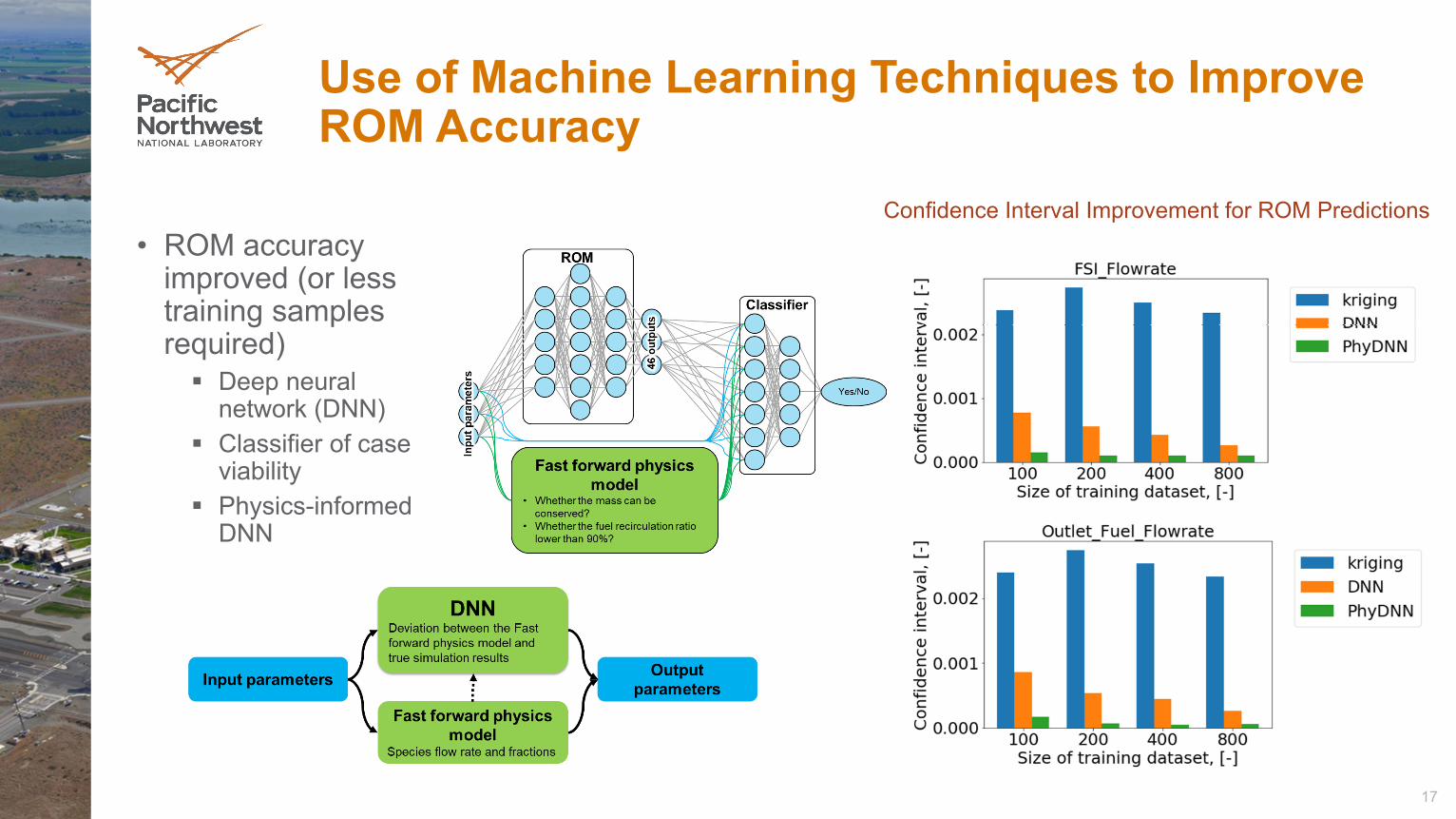
Use of Machine Learning Techniques to Improve ROM Accuracy
• ROM accuracy improved (or less training samples required) Deep neural
network (DNN) Classifier of case
viability Physics-informed
DNN
Confidence Interval Improvement for ROM Predictions
18
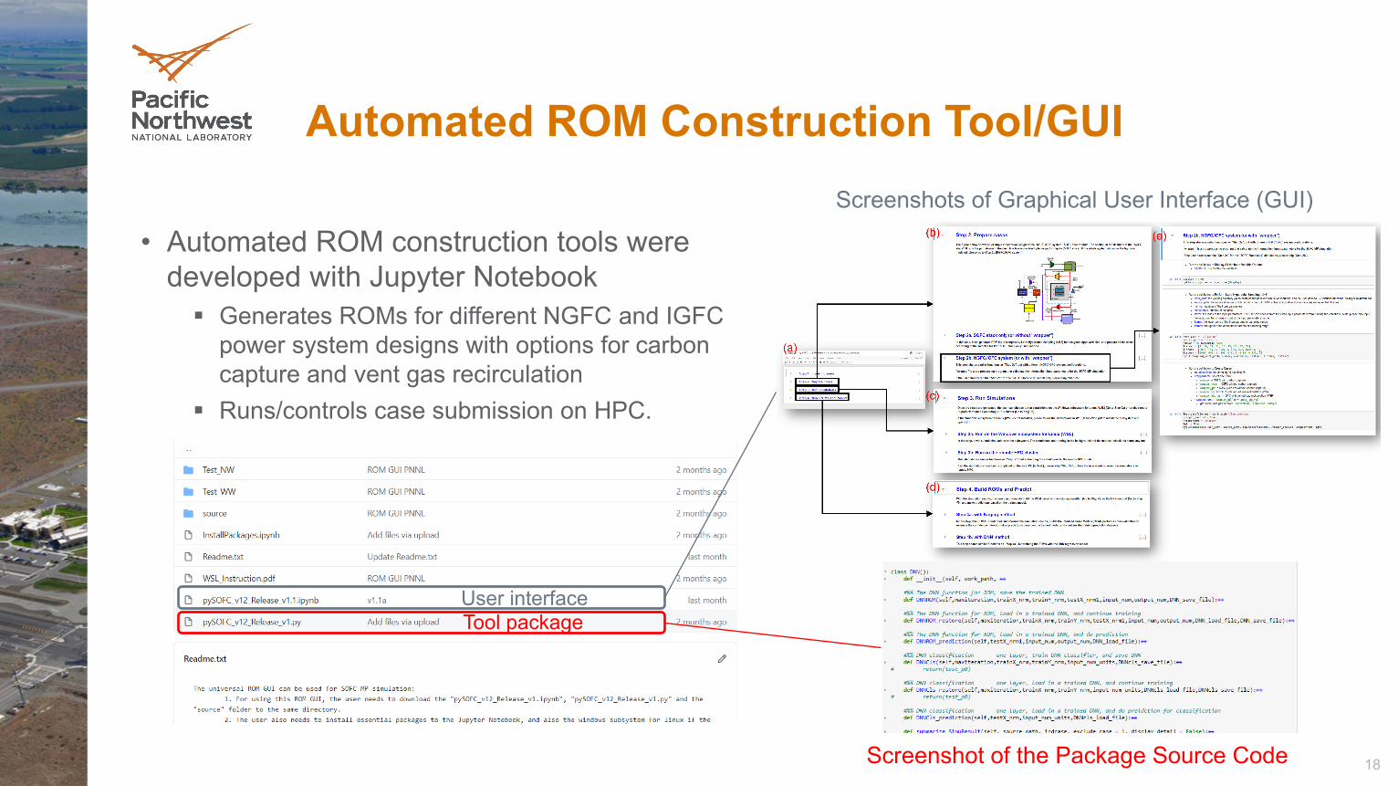
Automated ROM Construction Tool/GUI
• Automated ROM construction tools were developed with Jupyter Notebook Generates ROMs for different NGFC and IGFC
power system designs with options for carbon capture and vent gas recirculation
Runs/controls case submission on HPC.
Tool package
Screenshot of the Package Source Code
Screenshots of Graphical User Interface (GUI)
User interface
19
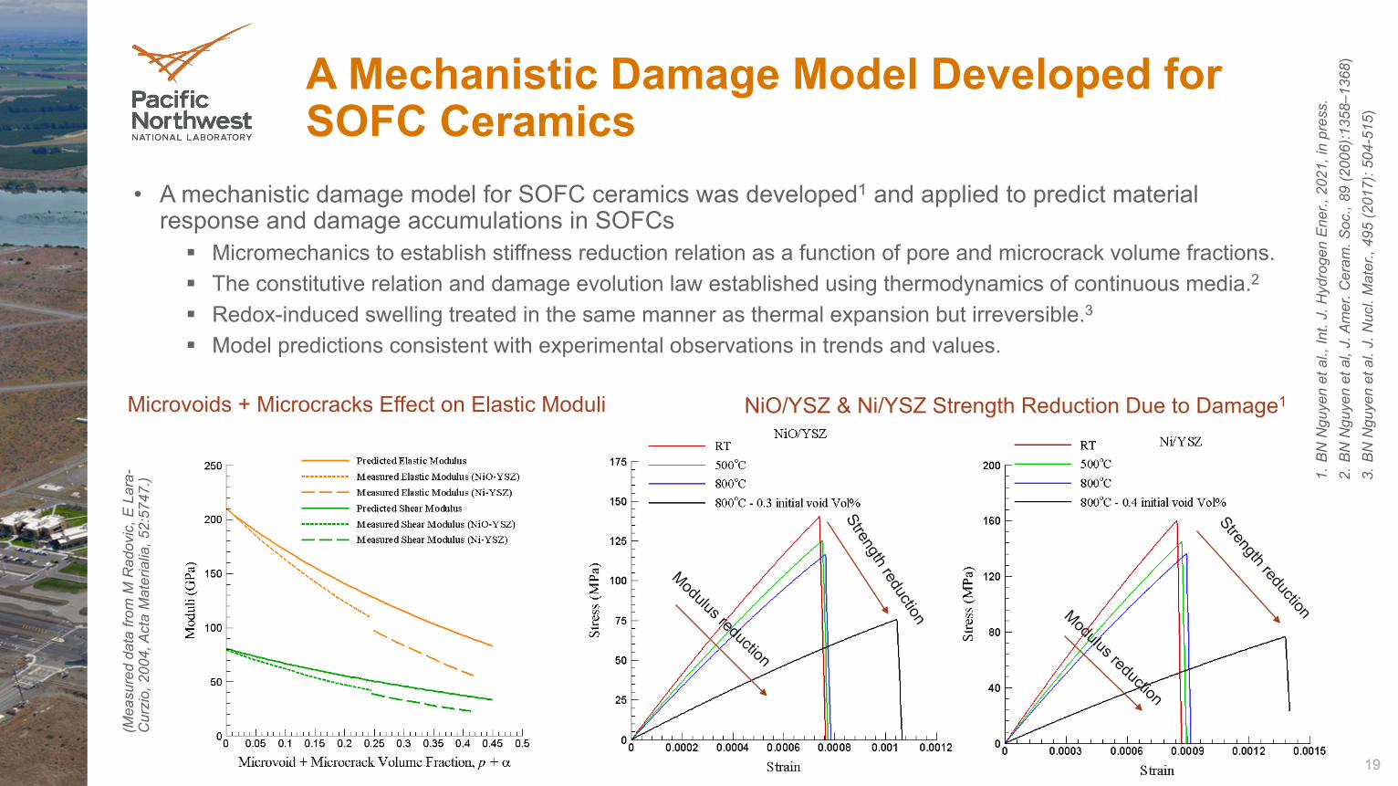
A Mechanistic Damage Model Developed for SOFC Ceramics
• A mechanistic damage model for SOFC ceramics was developed1 and applied to predict material response and damage accumulations in SOFCs Micromechanics to establish stiffness reduction relation as a function of pore and microcrack volume fractions. The constitutive relation and damage evolution law established using thermodynamics of continuous media.2
Redox-induced swelling treated in the same manner as thermal expansion but irreversible.3
Model predictions consistent with experimental observations in trends and values.
19
NiO/YSZ & Ni/YSZ Strength Reduction Due to Damage1Microvoids + Microcracks Effect on Elastic Moduli
1.B
N N
guye
n et
al.,
Int.
J. H
ydro
gen
Ene
r., 2
021,
in p
ress
.2.
BN
Ngu
yen
et a
l, J.
Am
er. C
eram
. Soc
., 89
(200
6):1
358–
1368
)3.
BN
Ngu
yen
et a
l. J.
Nuc
l. M
ater
., 49
5 (2
017)
: 504
-515
)
(Mea
sure
d da
ta fr
om M
Rad
ovic
, E L
ara-
Cur
zio,
200
4, A
cta
Mat
eria
lia, 5
2:57
47.)
20
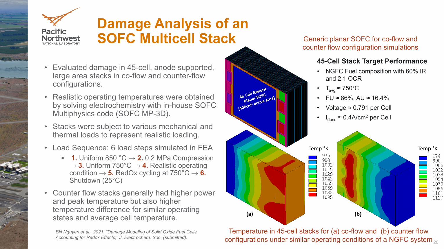
Damage Analysis of anSOFC Multicell Stack
• Evaluated damage in 45-cell, anode supported, large area stacks in co-flow and counter-flow configurations.
• Realistic operating temperatures were obtained by solving electrochemistry with in-house SOFC Multiphysics code (SOFC MP-3D).
• Stacks were subject to various mechanical and thermal loads to represent realistic loading.
• Load Sequence: 6 load steps simulated in FEA 1. Uniform 850 °C → 2. 0.2 MPa Compression
→ 3. Uniform 750°C → 4. Realistic operating condition → 5. RedOx cycling at 750°C → 6.Shutdown (25°C)
• Counter flow stacks generally had higher power and peak temperature but also higher temperature difference for similar operating states and average cell temperature.
45-Cell Stack Target Performance• NGFC Fuel composition with 60% IR
and 2.1 OCR• Tavg ≈ 750°C• FU ≈ 86%, AU ≈ 16.4%• Voltage ≈ 0.791 per Cell• Idens ≈ 0.4A/cm2 per Cell
Temp °K Temp °K
(a) (b)
Temperature in 45-cell stacks for (a) co-flow and (b) counter flow configurations under similar operating conditions of a NGFC system
Generic planar SOFC for co-flow and counter flow configuration simulations
BN Nguyen et al., 2021. “Damage Modeling of Solid Oxide Fuel Cells Accounting for Redox Effects,” J. Electrochem. Soc. (submitted).
21
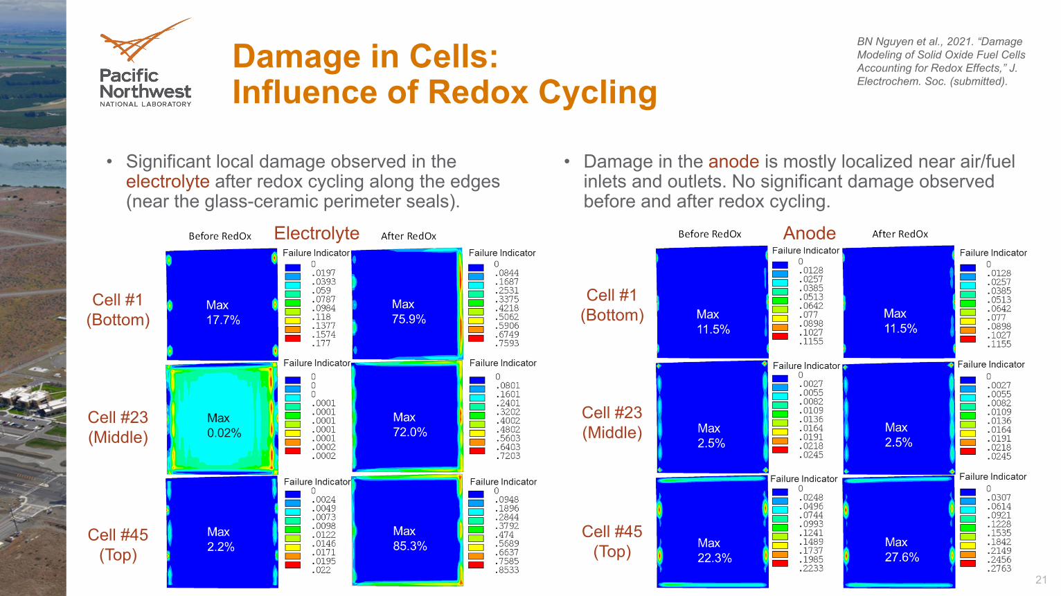
Damage in Cells:Influence of Redox Cycling
• Significant local damage observed in theelectrolyte after redox cycling along the edges(near the glass-ceramic perimeter seals).
• Damage in the anode is mostly localized near air/fuel inlets and outlets. No significant damage observed before and after redox cycling.
Electrolyte Anode
Cell #1 (Bottom)
Cell #23 (Middle)
Cell #45 (Top)
Cell #1 (Bottom)
Cell #23 (Middle)
Cell #45 (Top)
BN Nguyen et al., 2021. “Damage Modeling of Solid Oxide Fuel Cells Accounting for Redox Effects,” J. Electrochem. Soc. (submitted).
22
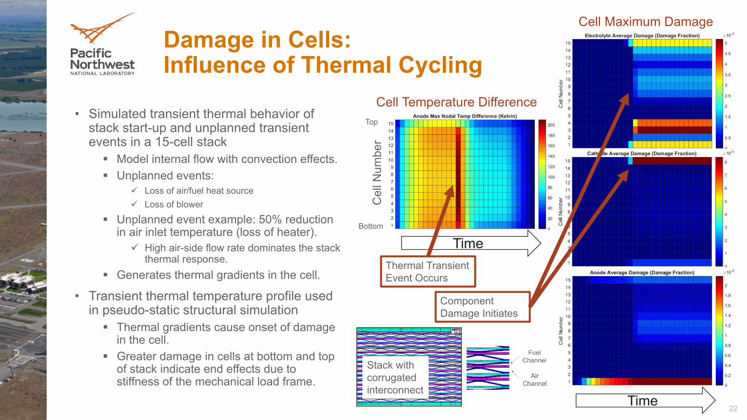
Damage in Cells:Influence of Thermal Cycling
• Simulated transient thermal behavior of stack start-up and unplanned transient events in a 15-cell stack Model internal flow with convection effects. Unplanned events:
Loss of air/fuel heat source Loss of blower
Unplanned event example: 50% reduction in air inlet temperature (loss of heater). High air-side flow rate dominates the stack
thermal response. Generates thermal gradients in the cell.
• Transient thermal temperature profile used in pseudo-static structural simulation Thermal gradients cause onset of damage
in the cell. Greater damage in cells at bottom and top
of stack indicate end effects due to stiffness of the mechanical load frame.
Time
Time
Cel
l Num
ber
Thermal Transient Event Occurs
Component Damage Initiates
Top
Bottom
Stack with corrugated interconnect
Cell Maximum Damage
Cell Temperature Difference
23
Acknowledgments
• This work has been funded by the SOFC Program of the US DOE Office of Fossil Energy and Carbon Management
• The NETL management team, including Debalina Dasgupta, Rin Burke, and Shailesh Vora, provided much helpful guidance and discussion
• Pacific Northwest National Laboratory is operated by Battelle Memorial Institute for the US Department of Energy