Embed Size (px)
Citation preview

19
JAPANESE DEVELOPMENT OF EARTHQUAKE RESISTANT BUILDING DESIGN
Shunsuke Otani Department of Architecture, Graduate School of Engineering
University of Tokyo 7-3-1 Hongo, Bunkyo-ku, Tokyo 113-8656
FAX: +81-3-5689-4673 E-mail: [email protected]
SUMMARY Development of Japanese earthquake-resistant building-design technology is reviewed. Significant developments occurred in determination of equivalent lateral forces after the 1923 Kanto Earthquake, but work on the ductile-design method for members did not begin until after the 1968 Tokachi-oki Earthquake. A general design concept of earthquake resistant buildings was formulated in the mid-1970s. Current earthquake resistant building design was formulated in the 1981 revision of Building Standard Law. Consequently, building damage from the 1995 Hyogo-ken Nanbu Earthquake varied significantly with the time of structural design prior to and after the implementation of important building code changes in 1971 and 1981. INTRODUCTION The Seismological Society of Japan was founded in 1880 by three European engineering professors invited at the Imperial College of Engineering in Tokyo. The 1891 Nohbi Earthquake (M 8.0) caused significant damage to then modern and western brick and masonry construction in Nagoya city, killing 7,273, collapsing 142,177 and damaging 80,184 timber houses. Brick and masonry construction was abandoned in Japan after the Nohbi earthquake disaster. The Association for Earthquake Disaster Reduction Investigation was organized by Japanese government in 1892 to develop the measures to improve earthquake resistance of building construction. Mr. Toshikata Sano (1880 - 1956), a pioneer researcher in earthquake engineering at the Imperial University of Tokyo, visited San Francisco after the 1906 San Francisco Earthquake, and recommended construction of reinforced concrete buildings in urban areas for the reason of earthquake resistance and fire protection. He published "Earthquake Resistance of Buildings" in 1914, in which he proposed the use of equivalent static horizontal loads in seismic design of buildings, and suggested a seismic coefficient of 0.3 in the downtown Tokyo area. He also pointed out the importance of strength, ductility and stiffness of

20
structural members. The first Japanese building code, Urban Building Law, was promulgated in April 1919, to regulate buildings in six major cities (Tokyo, Yokohama, Nagoya, Kyoto, Osaka, and Kobe). Building Law Enforcement Regulations, issued in November 1920, specified structural design for timber, masonry, brick, reinforced concrete and steel constructions on the basis of allowable stress design methods. Quality of materials, connections, reinforcement detailing, dead and live loads, and method of calculating stresses in section were prescribed in the regulations. Design against earthquake and high wind forces was not specified in 1920. The 1923 Kanto (Tokyo) Earthquake (M 7.9) caused significant damage in Tokyo and Yokohama areas, with loss of more than 140,000 lives, damaging more than 250,000 houses, burning more than 450,000 houses. Some significant damage was observed in steel and reinforced concrete construction. More than 90 percent of the dead and lost were caused by fire. The damage to reinforced concrete buildings was relatively low; out of 673 reinforced concrete buildings existed within Tokyo and surrounding areas, 15 buildings totally collapsed, 20 half-collapsed, 49 severely damaged, 74 lightly damaged, but 515 undamaged. More than seventy-five percent of reinforced concrete buildings survived with no damage. The reinforced concrete construction was proven to be earthquake and fire resistant by this earthquake. The damage was observed in buildings (a) with brick partition walls, (b) with little shear walls, (c) with poor reinforcement detailing, (d) with short lap splice length, (e) with poor beam-column connections, (f) with poor construction, (g) with irregular configuration, and (h) with poor foundation. Urban Building Law Enforcement Regulations were revised in June 1924 to introduce the use of seismic coefficient of 0.10 in structural design. The maximum ground acceleration of 0.3 g estimated in downtown Tokyo during the Kanto Earthquake was reduced to 0.10 by considering the safety factor of 3 used in determining allowable stress level relative to the material strength. No dynamic amplification in structural response was considered. Although seismic forces were specified in the regulation, no simple and practical methods of stress analysis were made available to practicing engineers in the 1920s. The Architectural Institute published "Standard for Structural Calculation of Reinforced Concrete Structures (AIJ RC Standard [1])" in April 1933. Professor Kiyoshi Muto (1903 - 1989) of the Imperial University of Tokyo introduced a simple D-value method of structural calculation for frame buildings. The method was based on the rigorous structural analysis theory, but various factors were prepared in table format for practical design use. BUILDING STANDARD LAW (1950 - to date) Building Standard Law, applicable to all buildings in Japan, was proclaimed in May 1950. The purpose of the law is to safeguard the life, health, and property of people by providing minimum standards concerning the site, structure, equipment, and use of buildings. The Law requires that a building owner must submit, before construction work, an application to building officials to confirm that the building, plan, site, structure and equipment satisfy the provisions of the law. The law does not prescribe technical issues, but it refers to the Building Standard Law Enforcement Order (Cabinet Order). Although the law and its accompanying cabinet order have been revised from time to time, the law and cabinet order govern the planning, design and construction of buildings in Japan. Technical standards for structural construction and structural calculation were specified in Chapter 3 “Structural Strength” of the Cabinet Order. The chapter consisted of 9 sections; (1) General Requirements, (2) Structural Members, (3) Timber Construction, (4) Masonry
21
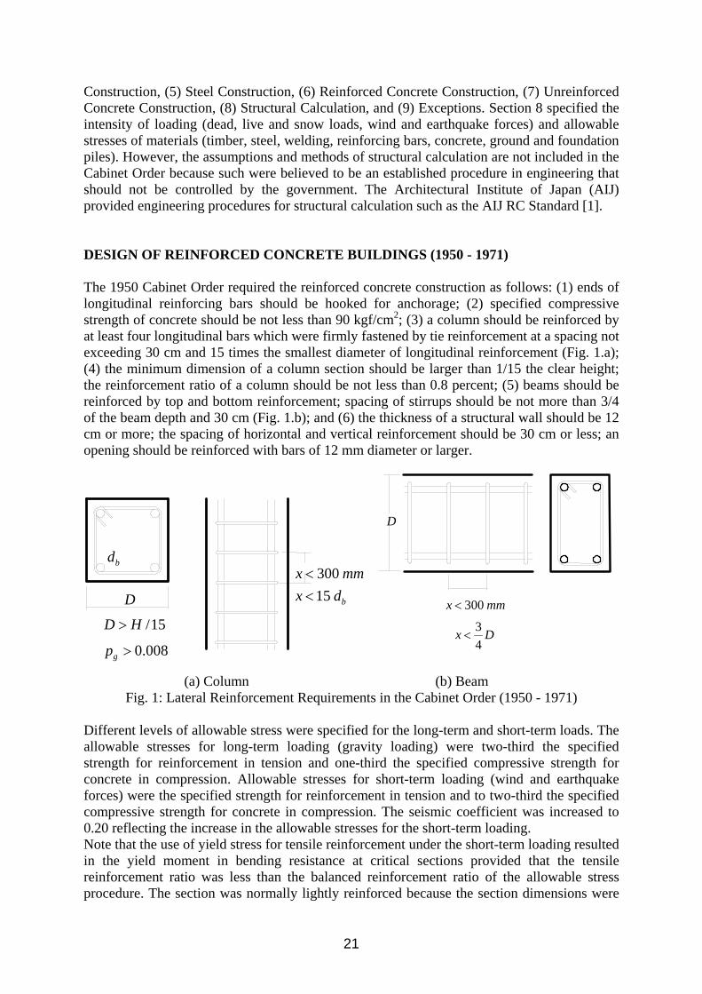
Construction, (5) Steel Construction, (6) Reinforced Concrete Construction, (7) Unreinforced Concrete Construction, (8) Structural Calculation, and (9) Exceptions. Section 8 specified the intensity of loading (dead, live and snow loads, wind and earthquake forces) and allowable stresses of materials (timber, steel, welding, reinforcing bars, concrete, ground and foundation piles). However, the assumptions and methods of structural calculation are not included in the Cabinet Order because such were believed to be an established procedure in engineering that should not be controlled by the government. The Architectural Institute of Japan (AIJ) provided engineering procedures for structural calculation such as the AIJ RC Standard [1]. DESIGN OF REINFORCED CONCRETE BUILDINGS (1950 - 1971) The 1950 Cabinet Order required the reinforced concrete construction as follows: (1) ends of longitudinal reinforcing bars should be hooked for anchorage; (2) specified compressive strength of concrete should be not less than 90 kgf/cm2; (3) a column should be reinforced by at least four longitudinal bars which were firmly fastened by tie reinforcement at a spacing not exceeding 30 cm and 15 times the smallest diameter of longitudinal reinforcement (Fig. 1.a); (4) the minimum dimension of a column section should be larger than 1/15 the clear height; the reinforcement ratio of a column should be not less than 0.8 percent; (5) beams should be reinforced by top and bottom reinforcement; spacing of stirrups should be not more than 3/4 of the beam depth and 30 cm (Fig. 1.b); and (6) the thickness of a structural wall should be 12 cm or more; the spacing of horizontal and vertical reinforcement should be 30 cm or less; an opening should be reinforced with bars of 12 mm diameter or larger.
(a) Column (b) Beam
Fig. 1: Lateral Reinforcement Requirements in the Cabinet Order (1950 - 1971) Different levels of allowable stress were specified for the long-term and short-term loads. The allowable stresses for long-term loading (gravity loading) were two-third the specified strength for reinforcement in tension and one-third the specified compressive strength for concrete in compression. Allowable stresses for short-term loading (wind and earthquake forces) were the specified strength for reinforcement in tension and to two-third the specified compressive strength for concrete in compression. The seismic coefficient was increased to 0.20 reflecting the increase in the allowable stresses for the short-term loading. Note that the use of yield stress for tensile reinforcement under the short-term loading resulted in the yield moment in bending resistance at critical sections provided that the tensile reinforcement ratio was less than the balanced reinforcement ratio of the allowable stress procedure. The section was normally lightly reinforced because the section dimensions were
D
300x mm<
34
x D<
D
30015 b
x mmx d<<
/15D H>
0.008gp >
bd

22
controlled by shear design. Horizontal earthquake force iF at floor level i was calculated by Eq. (1).
ii WKGZF = (1) where Z : seismic zone coefficient (0.8 to 1.0), G : soil-structure coefficient (0.6 to 1.0), K : seismic coefficient (0.20 to height of 16 m and below, increased by 0.01 for every 4.0 m above), iW : weight of story i. The soil-structure coefficient G was varied for soil conditions and for construction materials; e.g., for reinforced concrete construction, the coefficient was 0.8 for rock or stiff soil, 0.9 for intermediate soil, and 1.0 for soft soil. The AIJ RC Standard [1], revised in 1947 and 1949, requires the flexural resistance of section to be calculated on the basis of the “straight-line formula.” Design shear stress, Dv , of concrete was calculated by Eq. (2):
jbVv DD /= (2) where, DV : design shear force of a member, b: width of section, j: distance between the tensile and compressive resultants under bending (=7/8 d, d: effective depth of section). If the design shear stress under the long-term loading exceeded the allowable shear stress of concrete (one-thirtieth of the specified concrete strength), the difference might be assigned to shear reinforcement. However, if the design shear stress of concrete under the long-term or short-term loading exceeded the concrete allowable stress for the short-term loading (one-fifteenth of the specified concrete strength), all design shear stress had to be carried by the shear reinforcement. It was generally recommended that member dimensions should be selected large enough for the concrete to carry most of design shear stress and that minimum amount of lateral reinforcement should be placed to ease concrete work. REINFORCED CONCRETE BUILDING DESIGN FROM 1971 TO 1981 The 1968 Tokachi-oki Earthquake (M 7.9) caused significant damage to buildings in Aomori prefecture and Hokkaido with a death toll of 49. The number of totally collapsed buildings reached 673; approximately 10 percent of reinforced concrete buildings in the affected areas suffered some kind of damage including cracking. Short reinforced concrete columns typically in school buildings failed in shear. The damage raised some doubt about the earthquake resistance of reinforced concrete construction although no one was killed by the collapse of reinforced concrete buildings. The causes of damage were summarized as (1) poor concrete and reinforcement work, (2) uneven settlement of foundation, (3) lack of shear strength and ductility in columns, (4) failure of corner columns under bi-directional response, and (5) torsional response of buildings. The AIJ recommended that (1) shear stress level in columns should be kept low by the use of structural walls and by the use of larger section, (2) monolithic non-structural wall should be included in design structural analysis, (3) amount of shear reinforcement should be increased and placed effectively, and (4) ends of ties and hoops should be bent more than 135 degrees, or welded closed-shape hoops and spiral reinforcement should be used. Note that the shear resisting mechanism of a reinforced concrete member was not understood at the time. The Cabinet Order was revised in 1971 as an emergency measures to prevent shear failure of columns; i.e., (1) the diameter of hoops should be 6 mm or larger, and (2) the spacing should be 15 cm or less (10 cm or less within a range twice the smallest dimension of column section
23
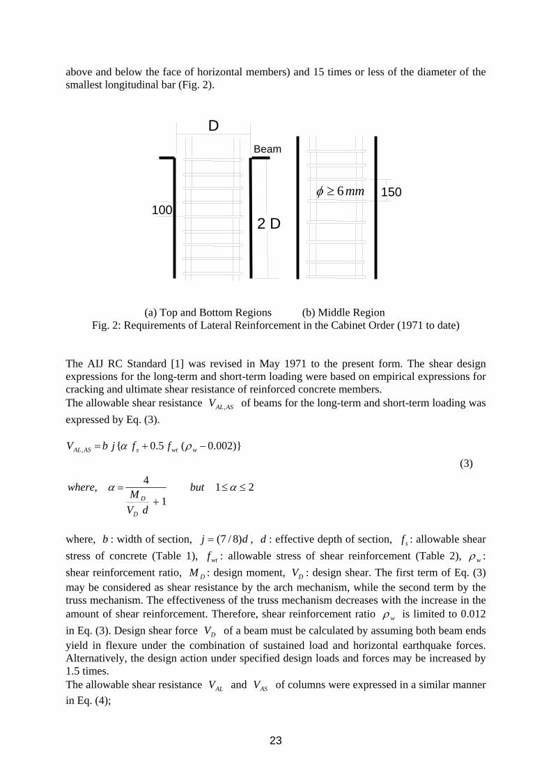
above and below the face of horizontal members) and 15 times or less of the diameter of the smallest longitudinal bar (Fig. 2).
(a) Top and Bottom Regions (b) Middle Region
Fig. 2: Requirements of Lateral Reinforcement in the Cabinet Order (1971 to date) The AIJ RC Standard [1] was revised in May 1971 to the present form. The shear design expressions for the long-term and short-term loading were based on empirical expressions for cracking and ultimate shear resistance of reinforced concrete members. The allowable shear resistance ASALV , of beams for the long-term and short-term loading was expressed by Eq. (3).
211
4,
)}002.0(5.0{,
≤≤+
=
−+=
αα
ρα
but
dVMwhere
ffjbV
D
D
wwtsASAL
(3)
where, b : width of section, dj )8/7(= , d : effective depth of section, sf : allowable shear stress of concrete (Table 1), wtf : allowable stress of shear reinforcement (Table 2), wρ : shear reinforcement ratio, DM : design moment, DV : design shear. The first term of Eq. (3) may be considered as shear resistance by the arch mechanism, while the second term by the truss mechanism. The effectiveness of the truss mechanism decreases with the increase in the amount of shear reinforcement. Therefore, shear reinforcement ratio wρ is limited to 0.012 in Eq. (3). Design shear force DV of a beam must be calculated by assuming both beam ends yield in flexure under the combination of sustained load and horizontal earthquake forces. Alternatively, the design action under specified design loads and forces may be increased by 1.5 times. The allowable shear resistance ALV and ASV of columns were expressed in a similar manner in Eq. (4);
D
2 D100
150 6mmφ ≥
Beam

24
loadingtermshortforpffjbV
loadingtermlongforfjbV
wwtsAS
sLA
−−+=
−=
)}002.0(5.0{
α (4)
Design shear force DV of a column may be calculated by one of the following procedures (Fig. 3); i.e., (a) shear force at the simultaneous flexural yielding at the top and bottom of the column, (b) shear force calculated by assuming flexural yielding at a column end and flexural yielding at the beam ends connected to the other end of the column, or (c) 1.5 times column shear under the design loads and forces. Note that the shear design is based on the capacity design concept in determining shear resistance as well as design shear force by this revision. It becomes more difficult to fail RC members in shear if the 1971 RC Standard is properly applied.
Fig. 3: Calculation of Column Design Shear in 1971 AIJ RC Standard
Table 1: Allowable Stresses of Concrete in AIJ RC Standard (1971) Long-term Loading Short-term Loading
Comp. Shear Comp. Shear f’c/3 f’c/30 but not more than
(5+f’c/100) (2/3)f’c 1.5 times value of long-term
loading f’c: Specified concrete compressive strength (kgf/cm2)
Table 2: Allowable Stresses of Reinforcing Bars (kgf/cm2) in AIJ RC Standard (1971) Steel Long-term Loading Short-term Loading Grade Tension/Comp Shear Reinf. Tension/Comp Shear Reinf. SR24, 1,600 1,600 2,400 2,400 SR30 1,600 2,000 3,000 3,000 SD30 2,000 2,000 3,000 3,000 SD35 2,200 2,000 3,500 3,000 SD40 2,200 2,000 4,000 3,000
Grade number after alphabetical symbols indicate yield stress in kgf/mm2. SR: Round Bars, SD: Deformed Bars. The size of hoops and stirrups should be not smaller than 9 mm in diameter. Spacing had to be not less than 10 cm; however, the spacing might be increased to 15 cm in a region 1.5
1yM
2yM 1 2y y
D
M MQ
h+
=
Beam Yielding
Beam Yielding

25
times the maximum section dimension away from the column top and bottom ends. The spacing might be relaxed to 20 cm if larger bars were used for shear reinforcement. Minimum shear reinforcement ratio was 0.2 percent. In a column where shear force was expected to increase during an earthquake, the use of welded closed-shape ties and hoops was recommended. The reinforcement detailing requirements differed slightly from that of the 1971 Cabinet Order. REINFORCED CONCRETE BUILDING DESIGN (1981 TO PRESENT) The Ministry of Construction organized an integrated technical development project (1972-1977), entitled "Development of New Earthquake Resistant Design." The 1978 Miyagi-ken Oki Earthquake caused damage to buildings with flexible first-story or with a large eccentricity between the centers of mass and stiffness. Therefore, the Cabinet Order was revised to the present form in July 1980 following the recommendations of the development project and was enforced from June 1981. The allowable stress design procedure was maintained. Major points of revision were listed below: (1) Shear reinforcement ratio must be 0.2 percent or more in a reinforced concrete member, (2) Design and construction of a building is made possible up to 60 m in height; the design and construction of buildings taller than 60 m must be approved by the Minister of Construction, (3) Additional requirements were introduced in structural calculation; (a) story drift, rigidity factor and eccentricity factor under design earthquake forces, (b) examination of story shear resisting capacity at the formation of a collapse mechanism under lateral forces, (c) alternative simple procedures for buildings with abundant lateral shear resisting capacity, (4) Design earthquake forces were specified (a) by story shear rather than horizontal floor forces, (b) as a function of fundamental period of the structure, (c) at two levels (allowable stress design and examination of story shear resisting capacity), and (d) also for the underground structures, (5) Strength of materials was introduced for the calculation of ultimate member resistance in estimating story shear resisting capacity, and (6) The story drift angle under the conventional earthquake forces (base shear coefficient of 0.20) must be not more than 1/200 of the story height. The material strength for concrete is the specified compressive strength of concrete f’c, and that for reinforcing bars is 1.1 times the specified yield strength fy for tension and compression. The material strength of shear reinforcement is the specified yield strength, but not more than 3,000 kgf/cm2. Design Elastic Story Shear The seismic (elastic response) story shear coefficient iC at story i is calculated by Eq. (5):
oiti CARZC = (5) where, Z: seismic zone factor (0.7 to 1.0), tR : vibration characteristic factor, iA : factor representing vertical distribution of the seismic story shear coefficient, oC : basic base shear coefficient (0.2 for allowable stress design and 1.0 for the examination of story shear resisting capacity).

26
The vibration characteristic factor tR (Fig. 4) represents the shape of design earthquake spectrum for three types of soil and is defined by Eq. (6):
TTforTT
R
TTTforTTR
TTforR
cc
t
ccc
t
ct
≤=
<≤−−=
<=
26.1
2}1{2.00.1
0.1
2 (6)
where, cT : dominant period of subsoil (0.4 sec for stiff sand or gravel soil, 0.6 sec for other soil, and 0.8 sec for alluvium mainly consisting of organic or other soft soil); T : natural period of the building. The natural period may be estimated by Eq. (7) for use in Eqs. (6) and (8):
HT 02.0= (7) where, H : total height of a reinforced concrete building in m.
Fig. 4: Vibration Characteristic Factor Rt The coefficient Ai is given by Eq. (8):
Natural Period, sec
Vib
ratio
n C
hara
cter
istic
Fac
tor
Soft Soil
Medium Soil
Hard Soil

27
TTA i
ii 31
2)1(1+
−+= αα
(8)
where ∑∑= 1/ WWiiα , and ∑ iW : total of dead and live loads above story i, and ∑ 1W : total dead and live loads of the building. The seismic coefficient k of underground part of a building is given by Eq. (9):
ZBk )40
1(1.0 −≥ (9)
where B: depth in meters below the ground level, but regarded as 20 in excess of 20 m. Story Shear Resisting Capacity Each story of a building must retain a story shear resisting capacity greater than the required story shear resisting capacity unQ defined by Eq. (10).
∑= iiessun WCFDQ (10) where, sD : structural characteristic factor, representing the ductility of hinging members of the story, esF : structural configuration factor, representing the distribution of stiffness and mass in a story, iC : story shear coefficient, ∑ iW : total dead and live loads above story i. Structural characteristic factor sD may be defined for each story and for a type of construction. For reinforced concrete construction, the values are given in Table 3, in which
uβ is the ratio of story shear carried by structural walls to the total story shear at the formation of a collapse mechanism under lateral loading.
Table 3: Structural Characteristic Factor Ds for Reinforced Concrete Buildings Amount of Walls in Structure
Performance of Structure 0 0 3≤ <βu . 0 3 0 7. .≤ <βu 0 7 1 0. .≤ ≤βu Excellent Ductility (A) 0.30 0.35 0.40 Good Ductility (B) 0.35 0.40 0.45 Reasonable Ductility (C) 0.40 0.45 0.50 Others (D) 0.45 0.50 0.55 βu : ratio of story shear carried by structural walls to the total story shear at the formation of a collapse mechanism.
The performance of structure is determined on the basis of the structural properties of those members which develop yielding or failure at the formation of a collapse mechanism (Fig. 5). The criteria for judging member structural ductility properties FA to FD for columns and girders (WA to WD for walls) are given in Table 4. Types FA to FC (or WA to WC) members are expected to develop flexural yielding while Types FD and WD members may fail in shear. If Types FD or WD members exist in a structure, possible consequence of brittle failure of such members must be carefully studied. A structure may be classified to be structural performance A if more than 50 percent of the story shear (excluding story shear carried by

28
Types FD and WD members) is carried by Types FA and WA members and less than 20 percent of the story shear is carried by Types FC and WC members. A structure may be classified to be structural performance B if less than 50 percent of the story shear (excluding story shear carried by Types FD and WD members) is carried by Types FC and WC members. A structure may be classified to be structural performance C if more than 50 percent of the story shear (excluding story shear carried by Types FD and WD members) is carried by Types FC and WC members.
Fig. 5: Yielding Member at Formation of Collapse Mechanism
Table 4: Classification of Member Performance (a) Columns
Classification FA FB FC FD Failure Modes Flexural Failure OthersMinimum (Clear Height ho/Width D) 2.5 2.0 - - Maximum (Axial Stress oσ /Concrete Strength f’c) 0.35 0.45 0.55 - Maximum Tensile Reinforcement Ratio pt 0.008 0.010 - - Maximum (Shear Stressvu/Concrete Strength f’c) 0.10 0.125 0.15 -
(b) Girders Classification FA FB FC FD Failure Modes Flexural Failure OthersMaximum (Shear Stressvu/Concrete Strength f’c) 0.15 0.20 - -
(c) Structural Walls Classification WA WB WC WD Failure Mode No shear failure OthersMaximum (Shear Stressvu/Concrete Strength f’c) 0.20 0.25 - -
Structural configuration factor esF considers the distribution of stiffness along the height of the structure and also the eccentricity of mass center with respect to the center of rigidity in a floor. The structural configuration factor is calculated as the product of factors sF and eF representing the irregularity of stiffness distribution in height and eccentricity in plan, respectively, as given in Eq. (11):
29
eses FFF = (11) The regularity in stiffness distribution along the structural height is judged by the value of rigidity ratio sR , defined by Eq. (12) at each story:
s
ss r
rR = (12)
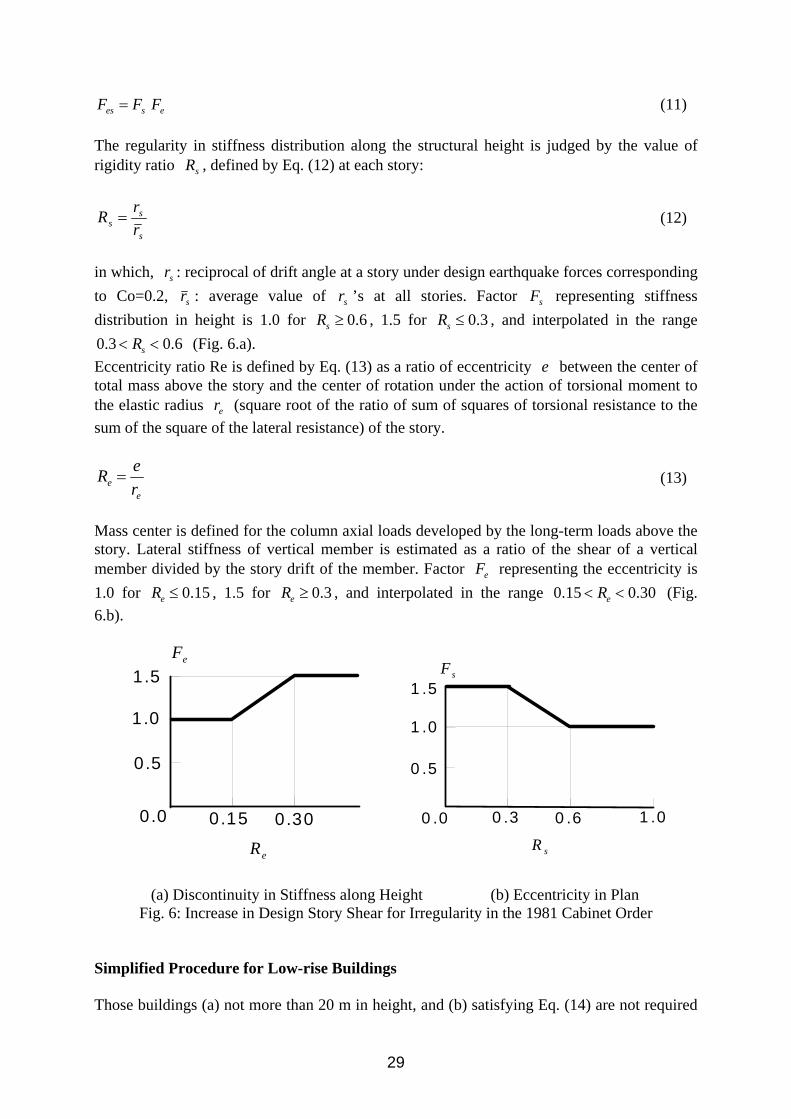
in which, sr : reciprocal of drift angle at a story under design earthquake forces corresponding to Co=0.2, sr : average value of sr ’s at all stories. Factor sF representing stiffness distribution in height is 1.0 for 0.6sR ≥ , 1.5 for 0.3sR ≤ , and interpolated in the range 0.3 0.6sR< < (Fig. 6.a). Eccentricity ratio Re is defined by Eq. (13) as a ratio of eccentricity e between the center of total mass above the story and the center of rotation under the action of torsional moment to the elastic radius er (square root of the ratio of sum of squares of torsional resistance to the sum of the square of the lateral resistance) of the story.
ee r
eR = (13)
Mass center is defined for the column axial loads developed by the long-term loads above the story. Lateral stiffness of vertical member is estimated as a ratio of the shear of a vertical member divided by the story drift of the member. Factor eF representing the eccentricity is 1.0 for 0.15eR ≤ , 1.5 for 0.3eR ≥ , and interpolated in the range 0.15 0.30eR< < (Fig. 6.b).
(a) Discontinuity in Stiffness along Height (b) Eccentricity in Plan
Fig. 6: Increase in Design Story Shear for Irregularity in the 1981 Cabinet Order Simplified Procedure for Low-rise Buildings Those buildings (a) not more than 20 m in height, and (b) satisfying Eq. (14) are not required
0 .0 0 .3 0 .6 1 .0
0 .5
1 .0
1 .5
sR
sF
0.0 0.15 0.30
0.5
1 .0
1.5
eR
eF

30
to examine the story shear resisting capacity;
iicw AWZAA ∑∑∑ ≥+ 725 (14) in which wA : horizontal area of structural walls in the direction of earthquake force (cm2),
cA : horizontal area of columns in the direction of earthquake force (cm2), Z: seismic zone factor, ∑ iW : sum of dead and live load above story i (kgf), iA : factor representing vertical distribution of the seismic story shear coefficient. Values 25 and 7 represent the approximate minimum shear strength per unit horizontal area of walls and columns (kgf/cm2), respectively. Those buildings (a) not more than 31 m in height, and (b) story drift angle less than 1/200 rad, (c) rigidity ratio sR not less than 0.6 (small discontinuity in stiffness along the height), and (c) eccentricity ratio eR not larger than 0.15 (small eccentricity between centers of stiffness and mass in plan), may satisfy any of the following three conditions: (a) iicw AWZAA ∑∑∑ ≥+ 75.0725 (15)
(b) iicw AWZAA ∑∑∑ ≥+ 1818 (16) (c) Girders and columns do not fail in shear calculated by assuming yielding at the member ends. The simplifying procedure is based on the observation of damage from the past earthquakes. Those buildings having sufficient structural walls are known to be earthquake resistant by their lateral load carrying capacity. BUILDING DAMAGE FROM KOBE EARTHQUAKE The 1995 Hyogo-ken Nanbu Earthquake, commonly known as Kobe Earthquake Disaster, occurred at around 5:46 am on January 17, 1995. The magnitude of the earthquake was intermediate and 7.2 defined by Japan Meteorological Agency. The earthquake hit a populated area of Kobe City, killing more than 6,300 (including those killed indirectly after the earthquake), injuring more than 40 thousands people, collapsing approximately 92,800 buildings and houses, and damaging approximately 192,700 buildings. Approximately 80 percent of the death were caused by the collapse of houses and buildings. The total loss was estimated to be more than 9,914 billion yen. The property losses in buildings amounted to 58.5 % of the total loss. The damage to reinforced concrete buildings may be characterized by (1) collapse in a middle story in office buildings, (2) collapse in the first story in apartment and condominium buildings, (3) significant loss incurred by the damage of non-structural members, (4) fracture at the splice of longitudinal reinforcement by gas-pressured welding technique, (5) damage in lightly reinforced beam-to-column connections, and (6) failure of foundation and piles. The Kinki (Osaka and Kyoto Region) Branch, Architectural Institute of Japan, investigated the damage of "all" existing reinforced concrete buildings (3,911 buildings in total) in a region, where the damage to buildings was reported to be highest [2]. The damage was evaluated from external observation of buildings by structural engineering researchers (including graduate students) and structural engineers. The investigation was carried out in August and September, 1995. Seventy-five (75) percent of the 3,911 buildings surveyed were residential buildings (including those used partially for office or shop). Forty-eight (47.5)

31
percent of the buildings were built in conformance with the current Building Standard Law (revised in 1981). Eighty-three (82.5) percent were lower than or equal to five stories high (73.0 % were from 3 to 5 stories high), Approximately ten (9.7) percent had soft first-story construction. The structural system of 76 % was either a moment-resisting frame system or a frame-wall system. The construction age was identified by (a) the plaque to commemorate the completion of construction, (b) the plaque at the installation of lightning rods, (c) the record at fire stations, or (d) detailed aerial photographs taken in 1971 and 1984. Damage levels were grouped into six levels in the investigation; i.e., (a) no damage, (b) little damage (columns, shear walls or non-structural walls were slightly damaged), (c) minor damage (columns or structural walls were slightly damaged, and some shear cracks were observed in non-structural concrete walls), (d) medium damage (typical shear and flexural cracks in columns, shear cracks in shear walls, or severe damage in non-structural concrete walls were observed), (e) major damage (spalling of concrete, buckling of reinforcement, and crushing or shear failure in columns were observed , and the lateral resistance of shear walls was reduced by heavy shear cracks) and (f) collapse. Those buildings demolished at the time of investigation were classified as "unknown". This paper uses three damage levels: i.e., (a) "operational damage" including no damage, little damage and minor damage, requiring no repair work for continuous use immediately after the earthquake, (b) "heavy damage" including medium damage and major damage, requiring significant repair and strengthening work for occupancy after the earthquake, and (c) "collapse" including collapse and unknown. Eighty-nine (88.5) percent of the 3,911 buildings surveyed suffered "operational damage", 5.9 percent suffered "heavy damage" and 5.7 percent collapsed. It should be emphasized that only 11.6 percent of the buildings suffered non-operational damage even in the areas of the highest seismic intensity in Kobe City. Among those 2,035 buildings constructed before the current Building Standard Law (1981), 7.4 percent suffered "heavy damage" and 8.3 percent collapsed. Among those 1,859 buildings constructed using the current Building Standard Law, 3.9 percent suffered "heavy damage" and 2.6percent collapsed. The 1981 revision of the Building Standard Law enhanced significantly the performance of reinforced concrete buildings against earthquake attack. On the other hand, the pre-1981 buildings need to be strengthened to the current building code level. The relation between damage level and the number of stories is shown in Tables 5 and 6 for buildings constructed before and after the enforcement of the current Building Standard Law in 1981.
Table 5: Damage of Buildings before 1981 No.
Stories Operational
Damage Heavy
Damage
Collapse
Total 1 20(90.9) 1( 4.5) 1( 4.5) 22(100) 2 215(92.7) 9( 3.9) 8( 3.4) 232(100) 3 532(93.0) 17( 3.0) 23( 4.0) 572(100) 4 524(85.8) 41( 6.7) 46( 7.5) 611(100) 5 269(79.6) 29( 8.6) 40(11.8) 338(100) 6 59(75.6) 10(12.8) 9(11.5) 78(100) 7 49(58.3) 16(19.0) 19(22.6) 84(100) 8 19(63.3) 7(23.3) 4(13.3) 30(100) 9 3(33.3) 4(44.4) 2(22.2) 9(100) 10 20(48.8) 15(36.6) 6(14.6) 41(100)
( ): Ratio to the number of buildings of the same height(%)

32
The ratio of severer damage increases with the number of stories, especially for buildings taller than 5 stories. The percentage of the pre-1981 buildings, which remained operational after the earthquake, is 87.9 percent for 1- to 5-story buildings, 66.1 percent for 6- to 8-story buildings, and 46.0 percent for 9-story and higher buildings. The corresponding percentages of the post-1981 buildings are 97.1, 87.1 and 70.7 percent, respectively. The revision of the law improved the level of safety almost uniformly from low-rise to mid-rise buildings. Even after the revision of the law, 20 percent of the buildings taller than seven stories suffered heavy damage or collapsed. A higher level of lateral force resistance is necessary to protect a high-rise building in the same manner as a low-rise building. The building owner should have been warned about a possible heavier damage in the tall building during an intense earthquake motion.
Table 6: Damage of Buildings after 1981 No.
Stories Operational Damage
Heavy Damage
Collapse
Total
1 8( 100) 0( 0.0) 0( 0.0) 8(100) 2 85(98.8) 0( 0.0) 1( 1.2) 86(100) 3 460(98.1) 2( 0.4) 7( 1.5) 469(100) 4 508(95.7) 9( 1.7) 14( 2.6) 531(100) 5 333(97.4) 5( 1.5) 4( 1.2) 342(100) 6 135(91.8) 9( 6.1) 3( 2.0) 147(100) 7 90(86.5) 12(11.5) 2( 1.9) 104(100) 8 44(75.9) 11(19.0) 3( 5.2) 58(100) 9 19(73.1) 7(26.9) 0( 0.0) 26(100) 10 51(69.9) 18(24.7) 4( 5.5) 73(100)
( ): Ratio to the number of buildings of the same height (%)
The damage of soft first-story buildings was more serious. The damage of the soft first-story buildings and other buildings are compared in Table 7. The percentage of collapsed buildings was three times more for the soft first-story construction compared to the other construction.
Table 7: Damage of Soft First-story Buildings Structures
Operational Damage
Heavy Damage
Collapse
Total
Soft First Buildings
275(72.3)
54(14.2)
51(13.4)
380 (100)
Other Buildings
3,186(90.2)
174(4.9)
171(4.8)
3,531 (100)
Seventy-two (72.3) percent of the soft first-story buildings were operational compared to ninety (90.2) percent of the other buildings. The percentage of the collapsed buildings was much higher for the soft first-story buildings, especially for those buildings constructed before the 1981 revision of the law. Major cause of the collapse was brittle shear failure of the first-story columns attributable to lack of shear reinforcement or to poor detailing at the ends of ties (90 degree bends). The performance of post 1981 buildings was improved partially attributable to (a) the improvement in the design against shear failure by the 1971 revision of the law enforcement order, (b) the improvement in the construction practice of tie reinforcement detailing (135 degree bends at the ends), and (c) the enhanced design story shear in a story with significant reduction in stiffness and in a story consisting of less ductile members.

33
The choice of structural system affected the damage; i.e., 77 percent of box wall systems suffered “no” damage and 21 percent suffered light and minor damage. Only remaining 2 percent of the box wall systems suffered heavy damage (often in the foundation) or collapsed. The boxed wall system has been used in Japan for dominantly residential buildings of less than six stories. The system is normally designed by prescriptive design guidelines. Partial reasons of low damage rate in the surveyed area may be attributed to the followings: (1) Majorities (82 %) of the buildings were low-rise buildings not taller than 5 stories; the heavier damage increased with the building height. (2) Majorities (47.5 %) of the buildings were constructed in conformance with the current Building Standard Law (revised in 1981); heavy damage was significantly reduced by the revision of the Building Standard Law in 1981. (3) Majorities (75.4 %) of the buildings were for residential use, which could easily accommodate structural walls or which used a boxed wall system of construction. (4) Less damage might have likely been identified by the external observation of a building. The damage rate must have been heavier in a region with old buildings and tall office buildings. CONCLUSIONS The technical development of earthquake resistant-building construction reduced significantly vulnerability of new construction. Although majority of existing buildings may achieve the purpose of structural design, some of the buildings constructed prior to the development need careful attention and may require retrofitting work. The structural damage can be significantly reduced by regulating (a) the brittle modes of member failures such as shear failure of reinforced concrete columns, (b) the discontinuity in stiffness and strength along the height of buildings, (c) the eccentricity between the centers of mass and stiffness in plan, (d) the irregular configuration of structures in plan, and controlling the quality of construction work. The experience from the Kobe earthquake disaster indicated the desirability of higher resistance of structures to control the damage for immediate use after an intermediate earthquake. REFERENCES 1. Architectural Institute of Japan, “Standard for Structural Calculation of Reinforced Concrete Structures,” published in 1933, and revised in 1937, 1947, 1949, 1958, 1962, 1971, 1975, 1979, 1982, 1988, 1992. 2. Reinforced Concrete Committee, “Damage Investigation Report on Concrete Buildings, the 1995 Hyogo-ken Nanbu Earthquake (in Japanese),” Kinki Branch, Architectural Institute of Japan, 1966.