Embed Size (px)
Citation preview
77
SINC
E 1993
SINCE 2001
SINCE 2004
SPLIT-BODY
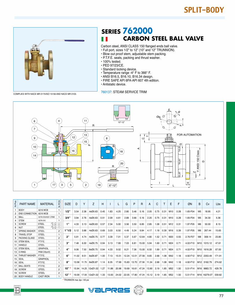
SERIES 762000 CARBON STEEL BALL VALVECarbon steel, ANSI CLASS 150 flanged ends ball valve.• Full port, sizes 1/2” to 12” (10” and 12” TRUNNION).• Blow out proof stem, adjustable stem packing.• P.T.F.E. seats, packing and thrust washer.• 100% tested.• PED 97/23/CE.• Standard locking device.• Temperature range -4° F to 366° F.• ANSI B16.5, B16.10, B16.34 design.• FIRE SAFE API 6FA-API 607 4th edition.• Antistatic device.
760137: STEAM SERVICE TRIM
14
10
9
17 3 5 2
6 4
8
18
FOR AUTOMATIONT
A
C
LI
F
B
D
Y A
NS
I 150
Cla
ssZ
H
11
7
12
16
15
13
1 19
1.4408
R
GP
E
ØN
6”-12”
R20
10”-12”
PART NAME MATERIAL
1 BODY A216 WCB 12 END CONNECTION A216 WCB 13 BALL A276-316/A351 CF8M 14 STEM A276-316 15 SCREW 1/2”....2”
3”....8”48
6 NUT 1/2”....4” 6” - 8”
21
7 SPRING WASHER STEEL 28 TRAVEL STOP STEEL 19 PACKING GLAND STEEL 2
10 STEM SEAL P.T.F.E. 111 HANDLE STEEL 112 STEM SEAL GRAPHOIL 113 O-RING FKM (Viton®) 214 THRUST WASHER P.T.F.E. 115 SEAL GRAPHOIL 116 SEAL P.T.F.E. 117 BALL SEATS P.T.F.E. 218 SCREW STEEL 219 SCREW STEEL 220 BODY HANDLE CAST IRON 1
N P
CS
N P
os
STEELSTEEL
SIZE D Y Z H I L G P R A C T E F ØN B Cv Lbs
1/2” 3.54 2.38 4xØ0.63 0.45 1.83 4.25 2.80 3.46 5.16 2.05 0.75 0.31 M10 0.28 1.65-F04 M5 18.95 4.21
3/4” 3.94 2.76 4xØ0.63 0.51 2.09 4.61 2.89 3.66 5.16 2.20 0.75 0.31 M10 0.28 1.65-F04 M5 34.30 5.36
1” 4.33 3.13 4xØ0.63 0.57 2.34 5.00 3.56 3.50 6.85 2.85 1.08 0.51 M12 0.31 1.97-F05 M6 50.00 8.15
1”1/2 5.12 3.88 4xØ0.63 0.69 3.03 6.50 4.49 5.24 9.84 4.17 1.18 0.39 M16 0.39 1.97-F05 M6 267.44 15.65
2” 5.91 4.74 4xØ0.75 0.77 3.39 7.01 5.37 5.67 12.64 4.80 1.52 0.71 M20 0.55 2.76-F07 M8 308.14 23.80
3” 7.48 6.00 4xØ0.75 0.94 3.13 7.99 7.03 6.81 15.00 5.94 1.69 0.71 M24 0.71 4.02-F10 M10 1015.12 47.61
4” 9.06 7.50 8xØ0.75 0.94 4.33 9.02 8.21 7.36 15.00 6.50 1.69 0.71 M24 0.71 4.02-F10 M10 1616.28 67.00
6” 11.02 9.51 8xØ0.87 1.00 7.13 15.51 12.24 12.01 27.56 9.65 2.68 1.08 M42 1.18 4.92-F12 M12 2353.49 171.91
8” 13.58 11.75 8xØ0.87 1.14 8.35 17.99 15.83 13.70 27.56 11.34 2.68 1.08 M42 1.18 4.92-F12 M12 3162.79 274.62
10” * 15.94 14.25 12xØ1.02 1.27 11.88 20.98 19.69 16.61 47.24 13.90 3.19 1.85 M52 1.50 5.51-F14 M16 9883.72 429.78
12” * 19.09 17.00 12xØ1.02 1.33 13.93 24.02 22.05 17.80 47.24 15.12 3.19 1.85 M52 1.50 5.51-F14 M16 16279.07 559.82
COMPLIES WITH NACE MR 0175/ISO 15156 AND NACE MR 0103.
* TRUNNION max ∆p= 145 psi
124
SINC
E 1993
SINCE 2001
SINCE 2004
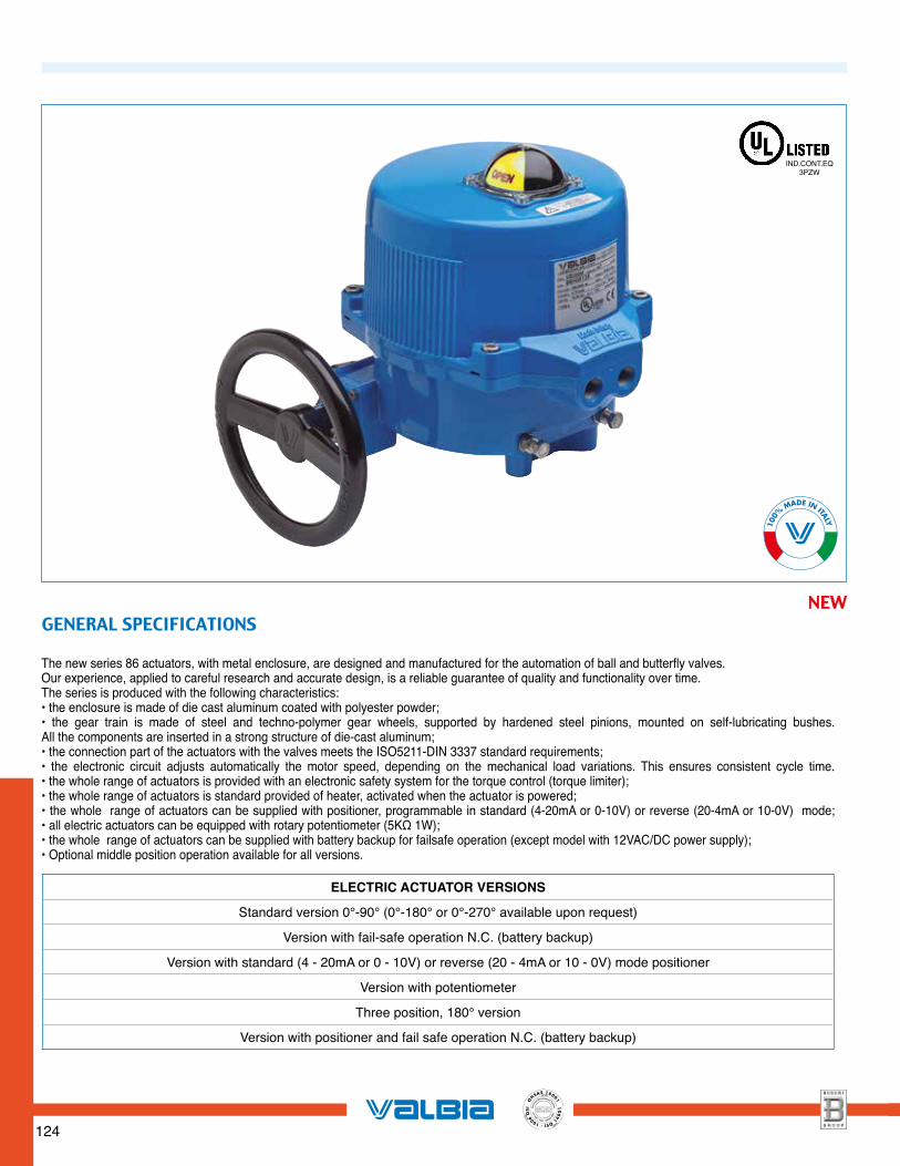
The new series 86 actuators, with metal enclosure, are designed and manufactured for the automation of ball and butterfly valves.Our experience, applied to careful research and accurate design, is a reliable guarantee of quality and functionality over time.The series is produced with the following characteristics:• the enclosure is made of die cast aluminum coated with polyester powder;• the gear train is made of steel and techno-polymer gear wheels, supported by hardened steel pinions, mounted on self-lubricating bushes. All the components are inserted in a strong structure of die-cast aluminum; • the connection part of the actuators with the valves meets the ISO5211-DIN 3337 standard requirements; • the electronic circuit adjusts automatically the motor speed, depending on the mechanical load variations. This ensures consistent cycle time.• the whole range of actuators is provided with an electronic safety system for the torque control (torque limiter); • the whole range of actuators is standard provided of heater, activated when the actuator is powered;• the whole range of actuators can be supplied with positioner, programmable in standard (4-20mA or 0-10V) or reverse (20-4mA or 10-0V) mode; • all electric actuators can be equipped with rotary potentiometer (5KΩ 1W);• the whole range of actuators can be supplied with battery backup for failsafe operation (except model with 12VAC/DC power supply); • Optional middle position operation available for all versions.
GENERAL SPECIFICATIONS NEW
IND.CONT.EQ3PZW
ELECTRIC ACTUATOR VERSIONS
Standard version 0°-90° (0°-180° or 0°-270° available upon request)
Version with fail-safe operation N.C. (battery backup)
Version with standard (4 - 20mA or 0 - 10V) or reverse (20 - 4mA or 10 - 0V) mode positioner
Version with potentiometer
Three position, 180° version
Version with positioner and fail safe operation N.C. (battery backup)
125
SINC
E 1993
SINCE 2001
SINCE 2004
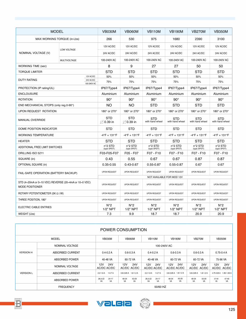
MODEL VB030M VB060M VB110M VB190M VB270M VB350M
MAX WORKING TORQUE (in-Lbs) 266 530 975 1680 2390 3100
NOMINAL VOLTAGE (V)
WORKING TIME (sec) 8 9 27 27 50 50TORQUE LIMITER STD STD STD STD STD STD
DUTY RATING
PROTECTION (IP rating/UL) IP67/Type4 IP67/Type4 IP67/Type4 IP67/Type4 IP67/Type4 IP67/Type4ENCLOUSURE Aluminium Aluminium Aluminium Aluminium Aluminium AluminiumROTATION 90° 90° 90° 90° 90° 90°END MECHANICAL STOPS (only reg.0-90°) NO NO STD STD STD STDUPON REQUEST ROTATION 180° or 270° 180° or 270° 180° or 270° 180° or 270° 180° or 270° 180° or 270°
MANUAL OVERRIDE STD0.39 in
STD0.39 in
STDwith hand wheel
STDwith hand wheel
STDwith hand wheel
STDwith hand wheel
DOME POSITION INDICATOR STD STD STD STD STD STD
WORKING TEMPERATURE -4°F + 131°F -4°F + 131°F -4°F + 131°F -4°F + 131°F -4°F + 131°F -4°F + 131°F
HEATER STD STD STD STD STD STDADDITIONAL FREE LIMIT SWITCHES n°2 STD
(type SPDT)n°2 STD(type SPDT)
n°2 STD(type SPDT)
n°2 STD(type SPDT)
n°2 STD(type SPDT)
n°2 STD(type SPDT)
DRILLING ISO 5211 F03-F05-F07 F05 - F07 F07 - F10 F07 - F10 F07 - F10 F07 - F10SQUARE (in) 0.43 0.55 0.67 0.67 0.87 0.87OPTIONAL SQUARE (in) 0.35-0.55 0.43-0.67 0.55-0.87 0.55-0.87 0.67 0.67
FAIL-SAFE OPERATION (BATTERY BACKUP) UPON REQUEST UPON REQUEST UPON REQUEST UPON REQUEST UPON REQUEST UPON REQUEST
STD (4~20mA or 0~10 VDC) REVERSE (20~4mA or 10~0 VDC) MODE POSITIONER
UPON REQUEST UPON REQUEST UPON REQUEST UPON REQUEST UPON REQUEST UPON REQUEST
ROTARY POTENTIOMETER (5K Ω 1W) UPON REQUEST UPON REQUEST UPON REQUEST UPON REQUEST UPON REQUEST UPON REQUEST
THREE POSITION, 180° UPON REQUEST UPON REQUEST UPON REQUEST UPON REQUEST UPON REQUEST UPON REQUEST
ELECTRIC CABLE ENTRIES N°21/2” NPT
N°21/2” NPT
N°21/2” NPT
N°21/2” NPT
N°21/2” NPT
N°21/2” NPT
WEIGHT (Lbs) 7.3 9.9 18.7 18.7 20.9 20.9
MULTIVOLTAGE 100-240V AC 100-240V AC 100-240V AC 100-240V AC 100-240V AC
LOW VOLTAGE24V AC/DC 24V AC/DC 24V AC/DC 24V AC/DC 24V AC/DC 24V AC/DC
12V AC/DC 12V AC/DC 12V AC/DC 12V AC/DC 12V AC/DC 12V AC/DC
NOT AVAILABLE FOR MOD 12V
100-240V AC
12V AC/DC
24V AC/DC100-240V AC
75%
50%
75%
50%
75%
50%
75%
50%
75%
50%
75%
50%
MODEL VB030M VB060M VB110M VB190M VB270M VB350M
NOMINAL VOLTAGE
ABSORBED CURRENT 0.4-0.2 A 0.6-0.3 A 0.4-0.2 A 0.6-0.3 A 0.6-0.3 A 0.75-0.4 A
ABSORBED POWER 40-48 VA 60-72 VA 40-48 VA 60-72 VA 60-72 VA 75-96 VA
NOMINAL VOLTAGE
ABSORBED CURRENT
ABSORBED POWER
FREQUENCY
POWER CONSUMPTION
VERSION H
VERSION L
100-240V AC
50/60 HZ
12VAC/DC
24VAC/DC
12VAC/DC
24VAC/DC
12VAC/DC
24VAC/DC
12VAC/DC
24VAC/DC
12VAC/DC
24VAC/DC
2.2-1.8 A 1-0.7 A 2.2-1.8 A 1-0.7 A 3.8-2.85 A 1.8-1.2 A 3.8-2.85 A 1.8-1.2 A 4.75-3.65 A 1.95-1.65 A
26,5-22 VA
24-17 VA
12VAC/DC
24VAC/DC
3.8-2.85 A 1.8-1.2 A
46-34VA
43-29VA
26,5-22 VA
24-17 VA
46-34VA
43-29VA
46-34VA
43-29VA
57-44VA
47-40VA
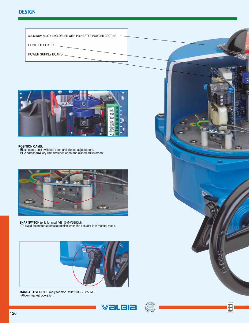
ALUMINUM ALLOY ENCLOSURE WITH POLYESTER POWDER COATING
CONTROL BOARD
POWER SUPPLY BOARD
DESIGN
POSITION CAMS:• Black cams: limit switches open and closed adjustement.• Blue cams: auxiliary limit switches open and closed adjustement.
SNAP SWITCH (only for mod. VB110M-VB350M):• To avoid the motor automatic rotation when the actuator is in manual mode.
MANUAL OVERRIDE (only for mod. VB110M - VB350M ):• Allows manual operation.
126
SINC
E 1993
SINCE 2001
SINCE 2004
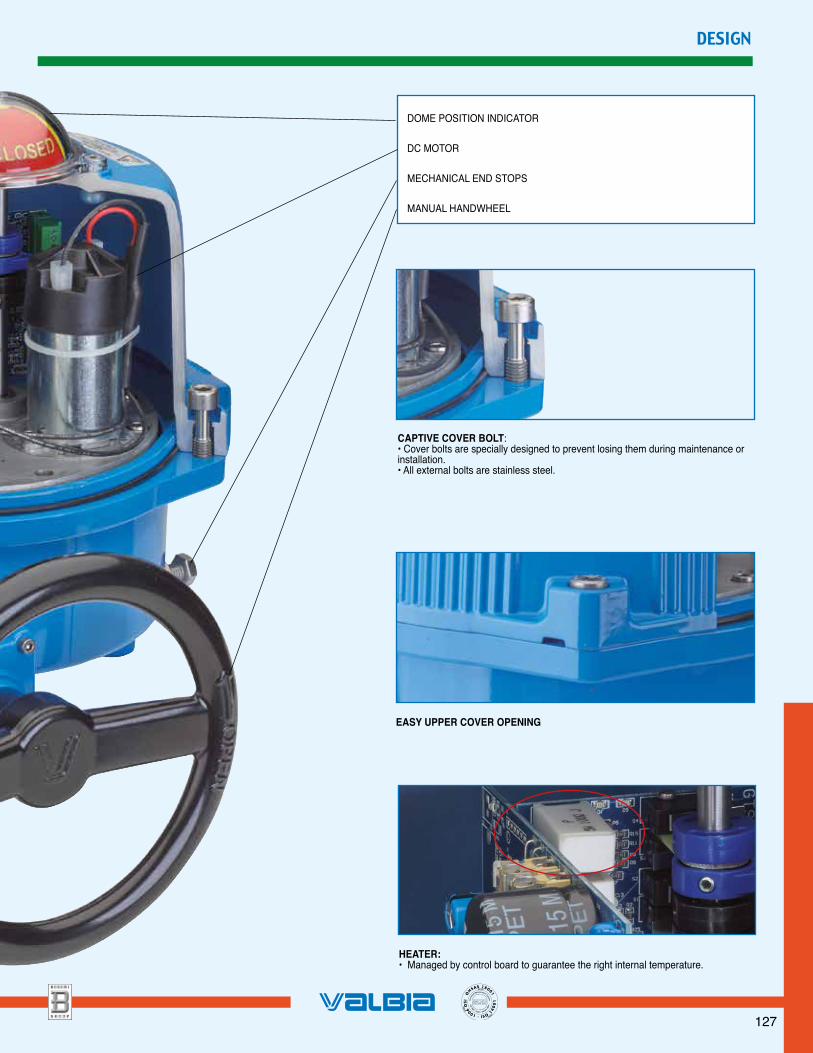
DOME POSITION INDICATOR
DC MOTOR
MECHANICAL END STOPS
MANUAL HANDWHEEL
DESIGN
CAPTIVE COVER BOLT:• Cover bolts are specially designed to prevent losing them during maintenance or installation.• All external bolts are stainless steel.
EASY UPPER COVER OPENING
HEATER:• Managed by control board to guarantee the right internal temperature.
127
SINC
E 1993
SINCE 2001
SINCE 2004
128
SINC
E 1993
SINCE 2001
SINCE 2004
E
GF
H
I
R
CH
QPO
N
M
L
n°2 1/2” NPT
B
C
DA
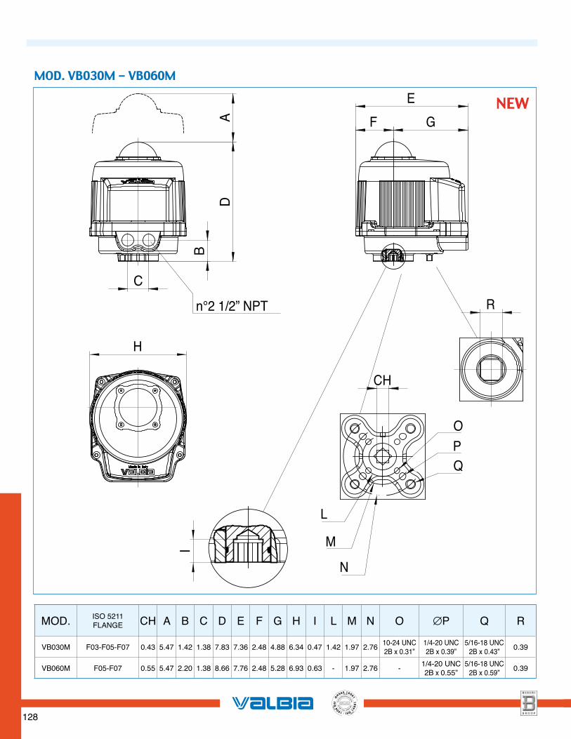
MOD. ISO 5211FLANGE CH A B C D E F G H I L M N O ∅P Q R
VB030M F03-F05-F07 0.43 5.47 1.42 1.38 7.83 7.36 2.48 4.88 6.34 0.47 1.42 1.97 2.76 10-24 UNC2B x 0.31”
1/4-20 UNC2B x 0.39”
5/16-18 UNC2B x 0.43” 0.39
VB060M F05-F07 0.55 5.47 2.20 1.38 8.66 7.76 2.48 5.28 6.93 0.63 - 1.97 2.76 - 1/4-20 UNC2B x 0.55”
5/16-18 UNC2B x 0.59” 0.39
MOD. VB030M - VB060M
NEW
129
SINC
E 1993
SINCE 2001
SINCE 2004
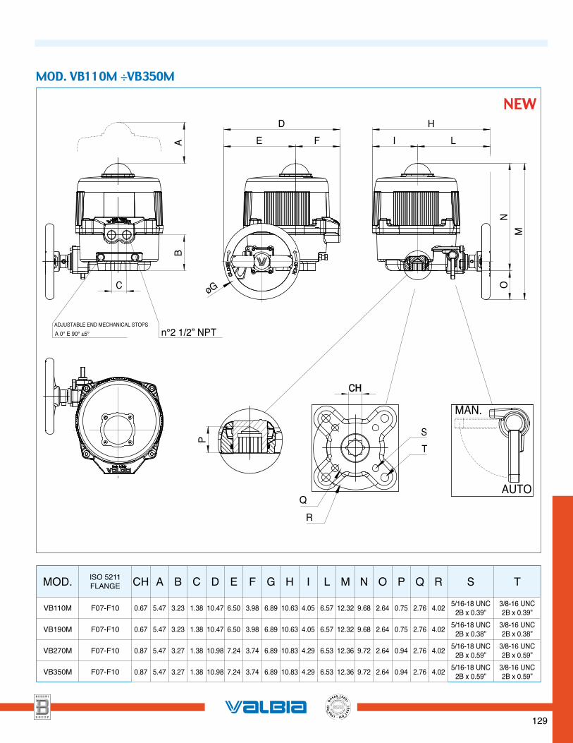
n°2 1/2” NPTADJUSTABLE END MECHANICAL STOPS
A 0° E 90° ±5°
AUTO
MAN.
C
B
I L
H
FE
D
NM
A
O
CH
P
øG
R
Q
T
S
MOD. ISO 5211FLANGE CH A B C D E F G H I L M N O P Q R S T
VB110M F07-F10 0.67 5.47 3.23 1.38 10.47 6.50 3.98 6.89 10.63 4.05 6.57 12.32 9.68 2.64 0.75 2.76 4.02 5/16-18 UNC2B x 0.39”
3/8-16 UNC2B x 0.39”
VB190M F07-F10 0.67 5.47 3.23 1.38 10.47 6.50 3.98 6.89 10.63 4.05 6.57 12.32 9.68 2.64 0.75 2.76 4.02 5/16-18 UNC2B x 0.38”
3/8-16 UNC2B x 0.38”
VB270M F07-F10 0.87 5.47 3.27 1.38 10.98 7.24 3.74 6.89 10.83 4.29 6.53 12.36 9.72 2.64 0.94 2.76 4.02 5/16-18 UNC2B x 0.59”
3/8-16 UNC2B x 0.59”
VB350M F07-F10 0.87 5.47 3.27 1.38 10.98 7.24 3.74 6.89 10.83 4.29 6.53 12.36 9.72 2.64 0.94 2.76 4.02 5/16-18 UNC2B x 0.59”
3/8-16 UNC2B x 0.59”
MOD. VB110M ÷VB350M
NEW
130
SINC
E 1993
SINCE 2001
SINCE 2004
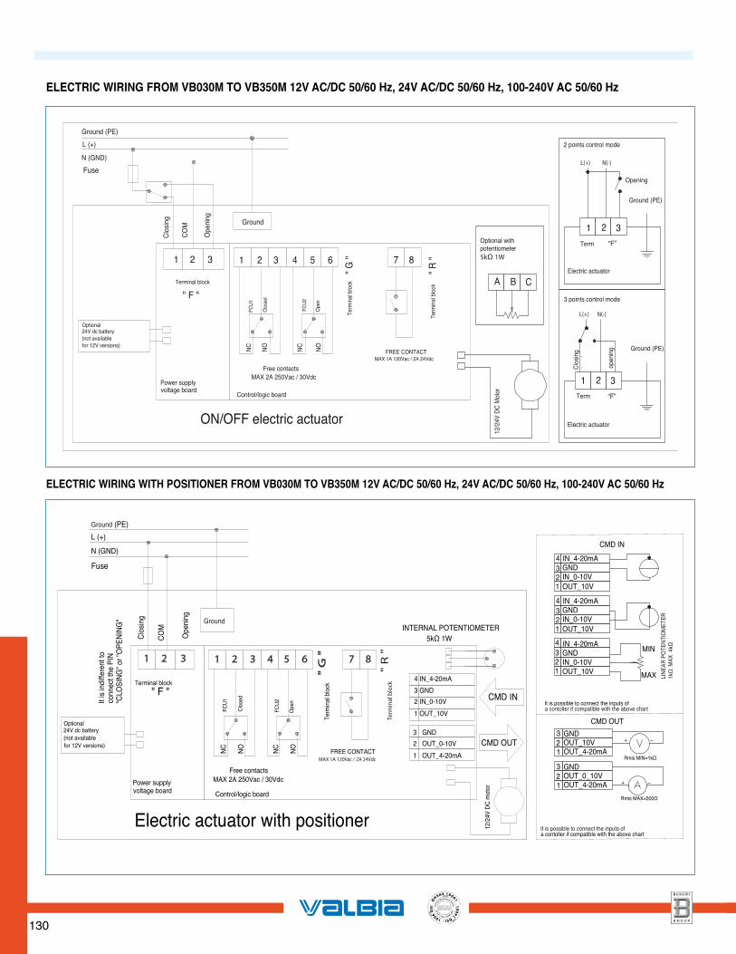
ELECTRIC WIRING FROM VB030M TO VB350M 12V AC/DC 50/60 Hz, 24V AC/DC 50/60 Hz, 100-240V AC 50/60 Hz
L(+) N(-)
N(-)L(+)
Ground (PE)
L (+)
N (GND)
Fuse
CO
M
Ope
ning
Clo
sing Ground
1 2 3 1 2 3 4 5 6
" F "Terminal block
Optional 24V dc battery (not availablefor 12V versions)
Power supply voltage board
FCU
1
FCU
2
Ope
n
Clo
sed
NC
NO
NC
NO
Free contactsMAX 2A 250Vac / 30Vdc
Control/logic board
FREE CONTACTMAX 1A 120Vac / 2A 24Vdc
Term
inal
blo
ck" R
"87
" G "
Term
inal
blo
ck
Optional with potentiometer5kΩ 1W
A B C
12/2
4V D
C M
otor
1 2 3
2 points control mode
Opening
Ground (PE)
Term
Electric actuator
3 points control mode
Clo
sing
open
ing
1 2 3Term
“F”
“F”
Ground (PE)
Electric actuatorON/OFF electric actuator
FREE CONTACT
" F "
Term
inal
blo
ck"
R "
" G
"
FCU
1
1 2 3 1 2 3 4 5 6
4 IN_4-20mA
3 GND
1
2
3
OUT_0-10V
OUT_4-20mA
GND
Ground
CO
M
Ground (PE)
L (+)
Ope
ning
N (GND)
Terminal block
FCU
2
Free contactsMAX 2A 250Vac / 30Vdc
MAX 1A 120Vac / 2A 24Vdc
NC
NO CMD OUT
CMD IN
Fuse
NC
NO
It is
indi
ffere
nt to
conn
ect t
he P
IN
"CLO
SIN
G" o
r "O
PEN
ING
"
Power supply voltage board
Optional 24V dc battery (not availablefor 12V versions)
Control/logic board
Ope
n
Clo
sed
Term
inal
blo
ck
Electric actuator with positioner
Clo
sing
12/2
4V D
C m
otor
INTERNAL POTENTIOMETER 5kΩ 1W
87
It is possible to connect the inputs ofa contoller if compatible with the above chart
2 IN_0-10V
1 OUT_10V
4321
4321
4321
IN_4-20mAGNDIN_0-10VOUT_10V
IN_4-20mAGNDIN_0-10VOUT_10V
IN_4-20mAGNDIN_0-10VOUT_10V
CMD IN
MIN
MAX
CMD OUT
LIN
EAR
PO
TEN
TIO
MET
ER1k
Ω. M
AX 4
kΩ
3 GND2 OUT_10V
OUT_4-20mA1
3 GND2 OUT_0_10V
OUT_4-20mA1
Rmis MIN=1kΩ
Rmis MAX=500Ω
It is possible to connect the inputs ofa contoller if compatible with the above chart
ELECTRIC WIRING WITH POSITIONER FROM VB030M TO VB350M 12V AC/DC 50/60 Hz, 24V AC/DC 50/60 Hz, 100-240V AC 50/60 Hz
131
SINC
E 1993
SINCE 2001
SINCE 2004
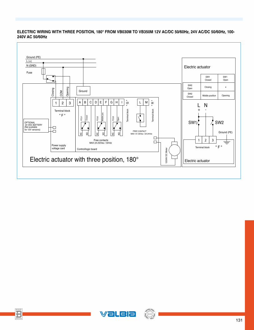
ELECTRIC WIRING WITH THREE POSITION, 180° FROM VB030M TO VB350M 12V AC/DC 50/60Hz, 24V AC/DC 50/60Hz, 100-240V AC 50/60Hz
SW2
Fuse
Electric actuator with three position, 180°
Ground
321
Power supplyvoltage card
OPTIONAL 24 VDC BATTERY
" F "Terminal block
COM
Open
ing
Control/logic board
Clos
ing
Term
inal b
lock
" G "
" R "
Term
inal b
lock
(Not availablefor 12V versions)
L M
Clos
ed
Midd
le po
s.
NONC NONC MAX 1A 120Vac / 2A 24Vdc
MAX 2A 250Vac / 30Vdc Free contacts
FCU2
FEDCBA
FCU1
FREE CONTACT
G H I
FCU3
NC NOOp
en
SW1Closed
SW1Open
SW2Open
SW2Closed
Closing -
Opening Middle position
Electric actuator
1 2 3
L+ -
N
SW1
Terminal block " F "
Electric actuator
Ground (PE)
L (+)N (GND)
Ground (PE)
12/
24V
DC M
otor


![AnchorChannels - ETA CE...[EN 100251 hot-dip galvan. 2 55 urn Carbon Steel Steel grade 4 6/8 8 [EN ISO 898-11 hot-dip galvan. 40 um Carbon Steel [EN 10025] hot-dip galvan. 40 um Carbon](https://img.pdfslide.tips/doc/110x75/6127865bed9e5a048a174ad0/anchorchannels-eta-ce-en-100251-hot-dip-galvan-2-55-urn-carbon-steel-steel.jpg)